GIGA TMS MINI400B Portable MSR Reader with Bluetooth User Manual Visio MINI400B User s Manual vsd
GIGA-TMS INC. Portable MSR Reader with Bluetooth Visio MINI400B User s Manual vsd
GIGA TMS >
Users Manual

*** USER’S MANUAL ***
FCC ID: WXAMINI400B
TM951241
- 1 -

Information
Technical And Operational Description
Card Data Format
Connections
......................................................................................... 3
6
9
10
..........................................
............................................................................
.........................................................................................
FCC COMPLIANCE STATEMENT
This equipment has been tested and found to comply with the limits for a
Class B digital device, pursuant to Part 15 of the FCC Rules. These limits are
designed to provide reasonable protection against harmful interference when
the equipment is operated in a commercial environment. This equipment
generates, uses, and can radiate radio frequency energy and, if not installed
and used in accordance with the instruction manual, may cause harmful
interference to radio communication.
Operation of this equipment in a residential area is likely to cause harmful
interference in which case the user will be required to correct the interference
at his own expense.
11
.....................................................................................
Specifications
12
.....................................................................
Communication Protocol
- 2 -
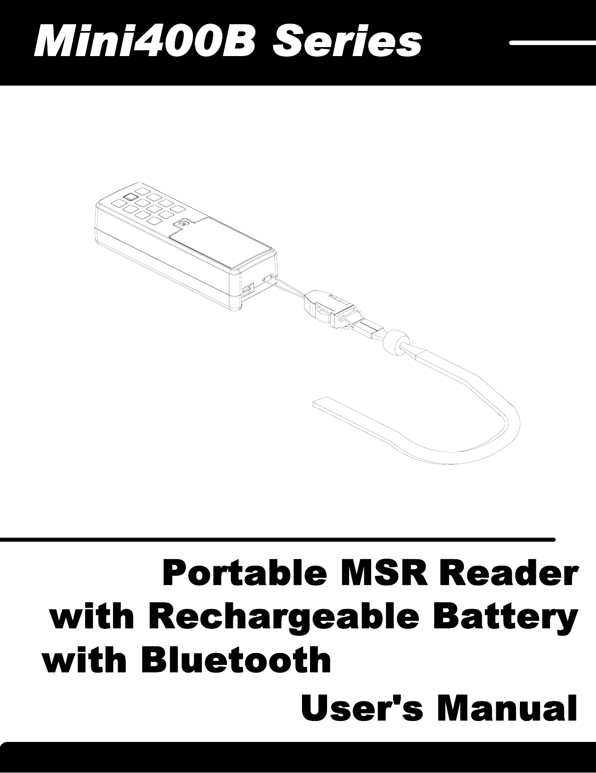
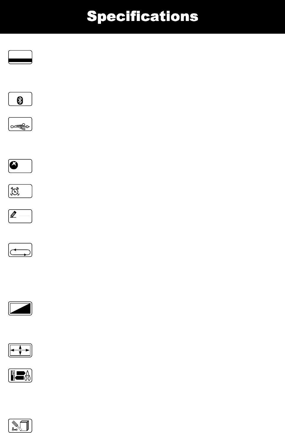
Mini400B Series Magnetic Swipe Reader
Mini400B
Track 1 & 2 & 3
MACHINE TYPE FUNCTION
GET
VER 1.2
N
F-MEM
512 KB
1 2 3
MC
OFF
AUTO
OFF
Muti-Charge
RTC
REC QUEUE
LED STATUS
Li-Polymer
Rechargeable
FFM
2048
USB
Ver 1.1
BlueTooth
Bluetooth adaptor Installation Refer to page10
1. Insert batteries into your device properly, with the (+) and (-) terminals aligned correctly.
2. Always fully charge your batteries before use.
3. When you charge the batteries for the first time, or if the batteries have been stored for a
long time, it normally takes about 3 charge and discharge cycles for the batteries to regain
full capacity.
4. It is normal for batteries to become hot during charging and they will gradually cool down
to room temperature after fully charged.
5. Store the batteries in a cool and dry place.
6. Remove batteries from the electrical device if the device is not going to be used for a long
time.
7. Keep battery contact surfaces and battery compartment contacts clean by rubbing them
with a clean pencil eraser or a rough cloth each time you replace batteries.
8. If the performance of the batteries decrease substantially, it is time to replace the
batteries.
9. Keep batteries away from children. If swallowed, contact a physician at once.
Read the instructions on your device before
installing batteries
- 3 -

Information
Lithium Ion Polymer Battery Handling
Guideline
It may cause the battery swelling, leaking, explosion or ignition, if you do not reading following:
1. Do not store battery in a manner that allows terminals to short.
2. The cell batteries are requested to be stored within a proper temperature range specified in this specifications.
3. Use only approved charger (Mini123EX).Improperly charging a cell or battery may cause the cell or battery to flame or
damage.
4. Prohibit reversing cell polarity within a battery assembly. The battery must be connected correctly.
5. Do not heat or dispose the battery into fire, water or other liquids.
6. Do not short-circuit a battery. Extended short-circuiting creates high temperature in the cell and at the terminals.
Physical contact to high temperature can cause skin burns. In addition, extended short-circuit may cause the cell or
battery to flame.
7. Do not bend, fold or fall the battery or part of the battery. It may cause the battery be damaged and result in the battery
swelling, leaking, explosion or ignition.
8. Do not open or manipulate the folded cell edge.
9. Do not bend or fold the sealing edge. And do not tear off the sealing film.
10. Do not drop or cause unnecessary shocks to the battery.
11. No sharp edge components shall be inside the battery housing. The sharp edge may destroy the cell packaging.
12. Do not carry loose batteries in a pocket or purse with metal objects like coins, paper clips and hair pins, etc. This will
short circuit the battery, generating high heat.
13. Do not directly heat cell body. It may cause the battery be damaged by heat above 90 .
14. Never disassemble a battery.
15. Never solder a battery.
Danger !
It may cause the battery swelling, leaking, explosion or ignition, if you do not reading following:
1. Do not put the battery into microware, washing machine or drying machine.
2. Do not put the battery onto oven.
3. Do not mixed batteries and types. Avoid to use old and new cells or cells of different sizes,different chemistry or
types in the same battery assembly.
4. Do not use a damaged battery.
5. Keep away batteries from children.
6. In case of contacting the materials from a damaged or ruptured cell or battery:
Eye contact: Washing immediately with plenty of water and soap or for at least 15 minutes. Get medical attention.
Skin contact: Washing immediately with water and soap.
Inhalation of Vented Gas: Remove to fresh air. Get medical attention.
Ingestion : Get medical attention immediately.
1. Do not place batteries near heating sources, nor exposed to direct sunlight for long periods. Elevated temperature
can result in reduced battery service life.
2. The battery shall be operated (stored, charged and discharged ) in the temperature specified in this specifications.
Operating Temperature:
Charging : 0 ~45
Discharge : -20 ~60
Storage -20 ~45
3. Do not overcharge or overdischarge batteries. It will decrease the batteries' service life.
Warning !
Caution !
* Manufactory has no liability for problems that occur when the above specifications are not followed.
- 4 -
Information
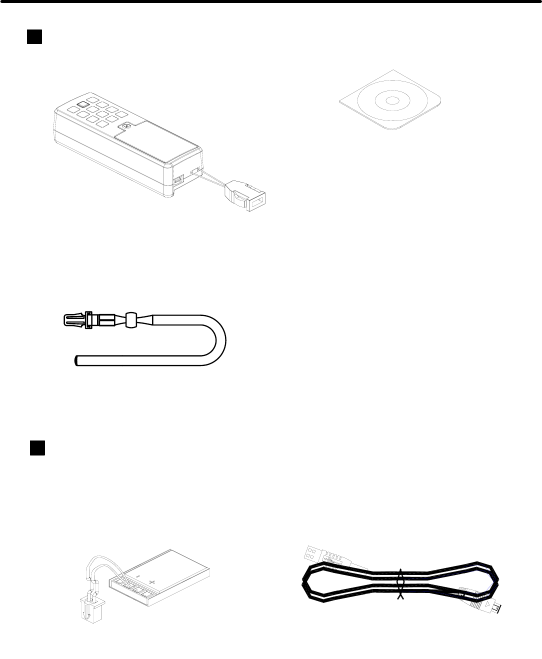
Standard Package
Main unit
( Mini400B )
Li-Polymer Rechargeable Battery
3.7V 250mAH
( BAT-T0011 )
Chain Sling
( TM09F1001 )
Option
USB Cable
( WAS-T0233 )
CD-ROM
( DISK5269 )
- 5 -
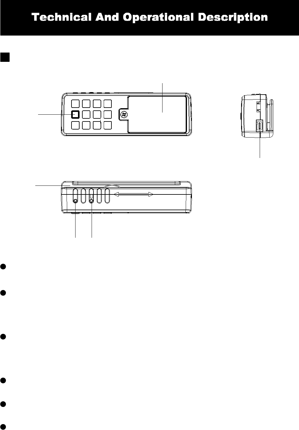
Battery Box
Power & Control
Button
Connector
Card
Reader
Bluetooth & Battery
Status LED indicator
Front Panel Display and Operations
Bluetooth & Battery Status LED Indicator
Indicating the bluetooth is standby, the bluetooth connection is ON or
OFF, the battery is ready ,charging progress , charge done, charge
suspend in charge mode or low battery in operational mode.
Power,Memory,Read Status LED Indicator
When encountering erroneous input, defective card, misread,bad
memory or incorrectly encoded data and so on, the device will turn on
the ERROR indicator .
Card Reader
Swipe the card through the entire length of the slot to read.
Battery Box
Put the battery in box and hold battery .
Connector
For connection to host computer and external Power for charge Battery .
Power & Control Button
Turn the Mini400B on/off power.
Power ,Memory ,Read Status
LED indicator
Note : Hold the power button for 3 sec for power off.
- 6 -
Technical And Operational Description
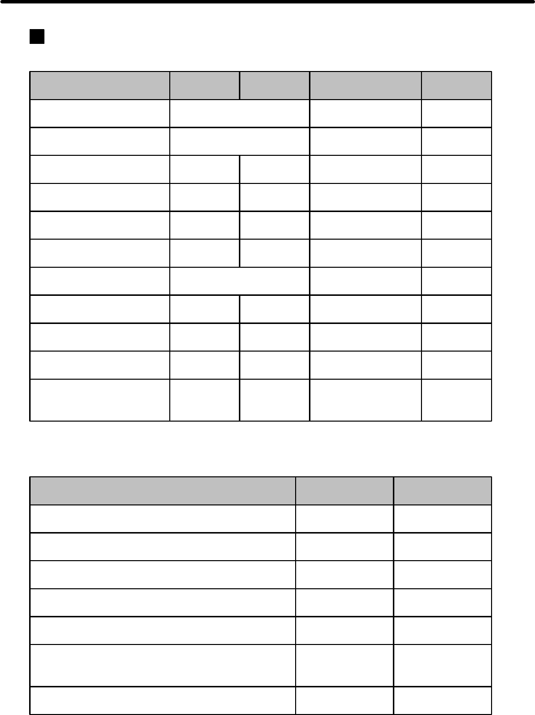
Display Information
Power,Memory,Read Status LED Indicator
Bluetooth & Battery Status LED Indicator
Blue LED
X
X
X
Red LED
Off
Off
Slow Blink
OnX
Fast Blink
X
X
Status
Power On
Ready
Read OK
Read Error
Memory Full
Memory bad
Green LED
Take turns blink
2 times
On
Blink
1 times
Off
Fast Blink
Off
Red LED
Off
Off
Blink
1 times
Off
Blink
Buzzer *1
Beep. Beep.
X
Beep.
Beep. Beep. Beep.
X
X
Inactive Battery Off Beep. Beep. Beep.
RTC No Setting Take turns blink X
Auto Power Off Beep. Beep.
Take turns blink
2 times
Blink
3 times
Read Card
X
O
X
X
X
X
X
X
X
Firmware Management
mode
Off On X X
Memory will be Full Slow Blink Off X O
Status
Precharge in progress
Charge done
Charge suspend
(temperature ,Timer Fault)
Low Battery
Fast charge in progress
Bluetooth connected
Bluetooth standby On X
Blink
- 7 -

Technical And Operational Description
Operational Description
1. Powered by Battery
For normal use, the unit is powered by battery. Push the Power Switch Button
for about 1.5 seconds to turn on the unit. Also push the Power Switch Button for about 1.5
seconds to turn off the unit. After the unit is turned on, the power would be turned off
automatically if there is no swiping a card on the unit in 30 seconds. This means the unit would
be turned off if no swiping a card again in every 30 seconds after every card swiping. It would
have Low Battery Detect/Warning indication when the unit is powered by battery.
2. Powered by Cable
3. Real Time Clock Setting
4. Low Battery Detect
When the unit is connected with the PC through the communication Cable (WAS-T0233) and
the PC is running Mini400B software and open the COM PORT for the unit, then the unit will be
turned on in about 0.5 second by the PC through the USB PORT. Then you can do the unit
Setting, Configuration or data downloading. When the software closes the COM PORT or exits,
the power turn off from the PC immediately. When powered by cable from PC, the Power Switch
would have no function and the unit would have no Low Battery Detect/Warning function.
Before start using the unit, you must set the Real Time Clock (RTC) inside the unit to your
local time. If there is no battery for quite a while or it is powered by cable for quite a while this
would cause Real Time clock (RTC) malfunctioned due to no power supply. When put on the
battery to turn on the unit and the Red/Green LED take turns blinking, this means the RTC is
malfunctioning and you must do the RTC time setting before you use the unit.
When powered by battery, it would have Low Battery Detect function. When the battery goes
low, the Bluetooth & Battery Status LED would flash red once every 2 second and you must
charge battery immediately, otherwise, the unit would shut down any time without pre-warning.
5. Charge Mode
6. Charge Status Indication
When Mini400B is in charge, Bluetooth & Battery Status LED Indicator light show slow blink red
that means the battery is in the pre-charge. When Bluetooth & Battery Status LED Indicator
light turns to red, it means the battery is in charge status. When Bluetooth & Battery Status
Indicator light turn off, it means the charge is finished. If the charge process has unusual
situation, Bluetooth & Battery Status Indicator light will show red fast blink. If Mini400B cable is
connected, and battery is not in charge, Bluetooth & Battery Status Indicator light will turn off.
7. Memory Low Warning
Log database memory is almost full (>90%). Adding new records is still possible but you are
advised to free up the log database memory by uploading the data to the PC as soon as
possible.
8. Memory Full Warning
Log database memory is full. You not be able to add any new records. Free the log database
memory by uploading the data to the PC.
There are three different charge modes for Mini400B: low battery mode ;real time mode and
manual charge mode. Low battery charge mode is used when the battery hits low voltage, it
starts to be charged automatically. Real time charge mode is whenever the Mini400B cable is
connected to USB, it would be charged immediately. Manual charge mode is the charge is
controlled by Demo software . User can use the software to start or stop charging. The default
set mode is on low battery charge mode.
9. Firmware Management mode (FMM)
FMM allows you to quickly upgrade your Mini123EX's internal firmware via com port and also
check validity of currently loaded firmware. Contact your dealer for most recent firmware
upgrade files.
10. Bluetooth Mode
For normal use, the unit is powered by battery. Push the Power Switch Button
for about 2.5 seconds to turn on the unit. the bluetooth will standby and Bluetooth & Battery
Status LED Indicator light show blue, when the unit will be turned on in by the PC through the
Bluetooth Adapter and the PC is running Mini400B software,the bluetooth will standby and
Bluetooth & Battery Status LED Indicator light show blink blue.
- 8 -
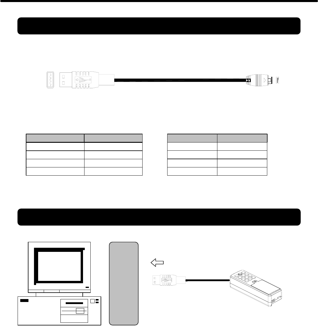
Personal Computer
USB
PORT
Connect to PC
WAS-T0233
1
1
Connections
Note:
1. When Mini400B is connected/disconnected to USB port, it would be turned On/Off automatically.
2. Normally the charging time is about 1.5 ~ 2.5 hours (Default setting is low battery charge mode, it is detected
when the battery is low, it would be charge until Full automatically). The working hours would be more than 48
hours (Stand alone and Always On). When Mini400B is connected with USB.
3. The battery life is more than 300 times. If user uses improperly charge mode, it may affect the battery life.
USB 4P FEMALE PIN
1
3
2
4
FUNCTION
VCC
D -
D +
GND
MINI USB 4P
1
3
2
4
FUNCTION
RXD
TXD
VCC
GND
Mini400B
- 9 -
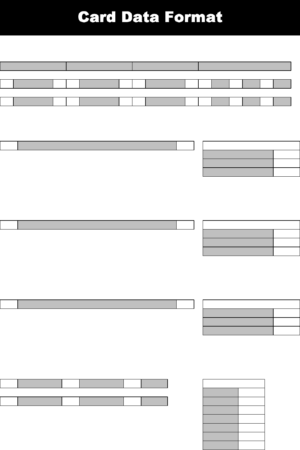
TRACK1 DATA
CARD DATA STRING
TRACK 1
SS ES
1. SS is the start sentinel ( % ).
2. ES is the end sentinel ( ? ).
3. Card Id up to 76 alphanumeric data characters.
CARD ID% ?
SS ESTRACK2 DATA SS ESTRACK3 DATA
TRACK1 DATA% ? ; ?TRACK2 DATA + ?TRACK3 DATA
TRACK 1 TRACK 2 TRACK 3
Bits Per Inch 210
Bits Per Character 7
Track 1 IATA
Alphanumeric Characters 79
TRACK 2
1. SS is the start sentinel ( ; ).
2. ES is the end sentinel ( ? ).
3. Card Id up to 37 numeric data characters.
CARD ID; ?
Bits Per Inch 75
Bits Per Character 5
Track 2 ABA
Numeric Characters 40
TRACK 3
1. SS is the start sentinel ( + ).
2. ES is the end sentinel ( ? ).
3. Card Id up to 104 numeric data characters.
CARD ID+ ?
Bits Per Inch 210
Bits Per Character 5
Track 3 Thrift
Numeric Characters 107
DATE & TIME
SP DATE SP TIME SP WEEK
DATE TIME WEEK
SP DATE
DATE&TIME&WEEK
SP TIME WEEKSP
1. SP is the SPACE characters ( 20h ).
2. TIME is 24hr .
YYYY/MM/DD SP HH:MM:SS WSP
WEEK
SUN
MON
TUE
WED
THU
FRI
SAT
1
2
3
4
5
6
7
- 10 -
Magnetic Stripe Card :
Bluetooth Interface :
Power Supply for Charge :
Dimensions :
Mounting :
Environment :
TRACK 1 / IATA / 210 bpi / 79 Alphanumeric Characters
TRACK 2 / ABA / 75 bpi / 40 Numeric Characters
TRACK 3 / Thrift / 210 bpi / 107 Numeric Characters
SPP Profile ,Class 2 ,Compatible Bluetooth V2.0+EDR,V1.2,V1.1
Battery Power :
Rechargeable Lithium-ion Polymer Battery
Nominal Capacity: 250 mAH ( Typical )
Nominal Voltage: 3.7 V
Cycle Life: 300 cycles ( at least )
Low Battery Detect and Built-in Quick Charge Circuit
AC DC DC 5V , 200mA ( for RS-232 ) or USB Powered
Charging duration time : 1.5 ~ 2.5 hr
Working duration time after charge : 48 hr ( always power on )
L 82 x W 27.5 x H 21 mm
%
C/F Operating Temp : -0℃~ +60℃( Discharge )
-0℃~ +45℃( Charging )
Storage Temp : -10 ~ +65℃
Humidity : 10 ~ 90 % relative
Portable or Any surface
1 2 3
MC
GNET
VER 1.2
Communication Protocol :
Version 1.2 (GNET V1.2)
Memory Size for Storing Data :
RTC CLOCK :
CMOS Serial Flash Memory 512K bytes
Up to 2048 records ( 256 Bytes / Record )
Real Time Clock (RTC) module and back-up capacitor
2048
REC QUEUE
Li-Polymer
Rechargeable
USB Interface
USB
Ver 1.1
Full compliance with the USB Specification V 1.1
The device uses a Virtual Serial Port Driver, making it appear to
have the software like a standard RS232 Serial Port.
BlueTooth
- 11 -
ACK
TX1
ACK
RX
NACK
TX2 TX4RX
RX
ERR
TIME
OUT
RX1 RX2
RX
NO
RX4
TX3
WAIT
RX
ACK
RX
NACK TIME OUT
Support TTY (TELE TYPE) OPERATION -
Use TTY to send commands and messages.
NACK
TX3
RX3
NACK
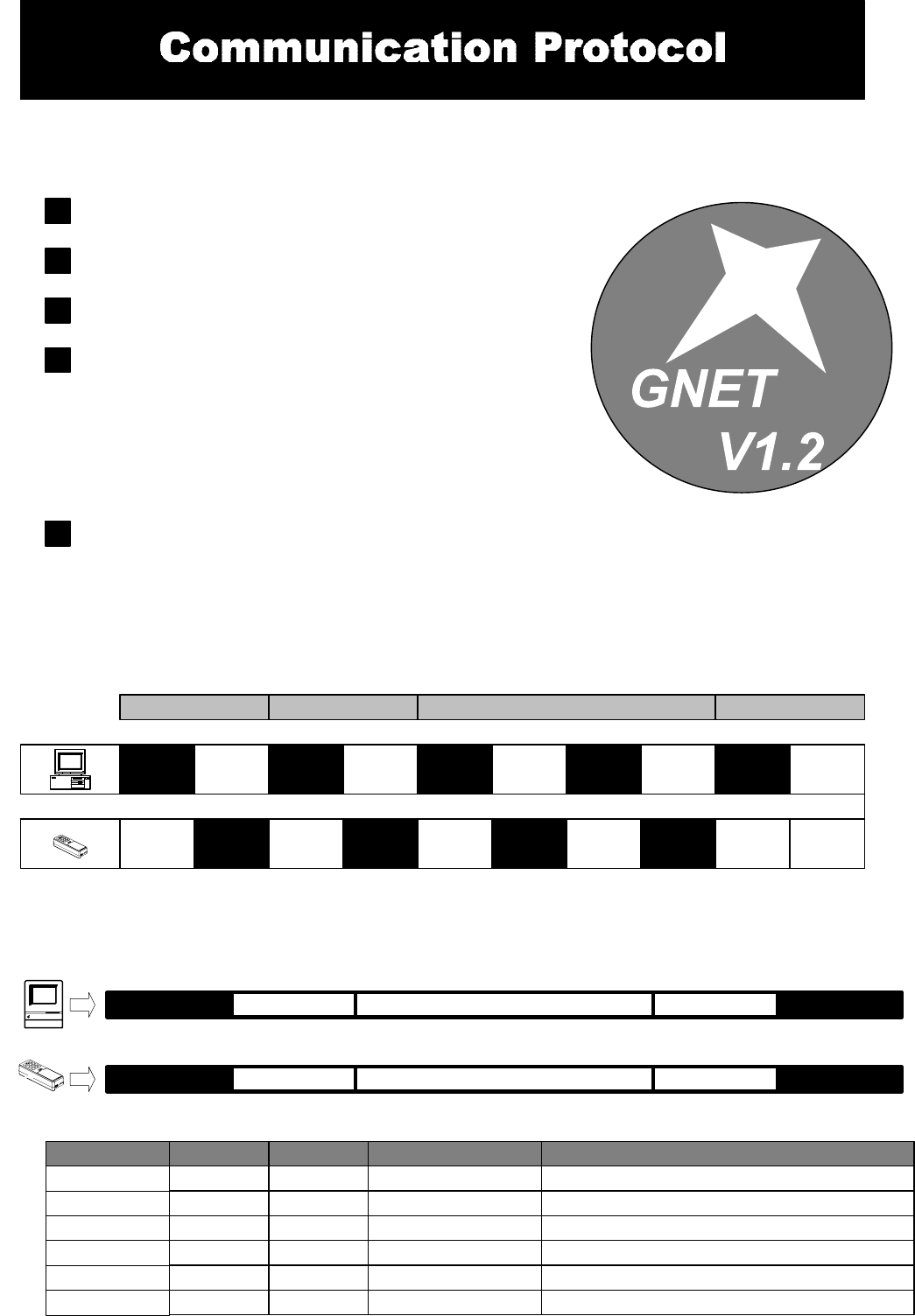
GNET FEATURES
Simple handshaking -
One enquiry one answer back.
Multi-link capability
Expandability -
GNET provides 4 major functions:
1. POLLING
2. LOGIN / LOGOUT
3. DATABASE
4. INFORMATION
Also can be expandable.
Simple format
Use ASCII value for each field and use Separator "," between two
Fields.
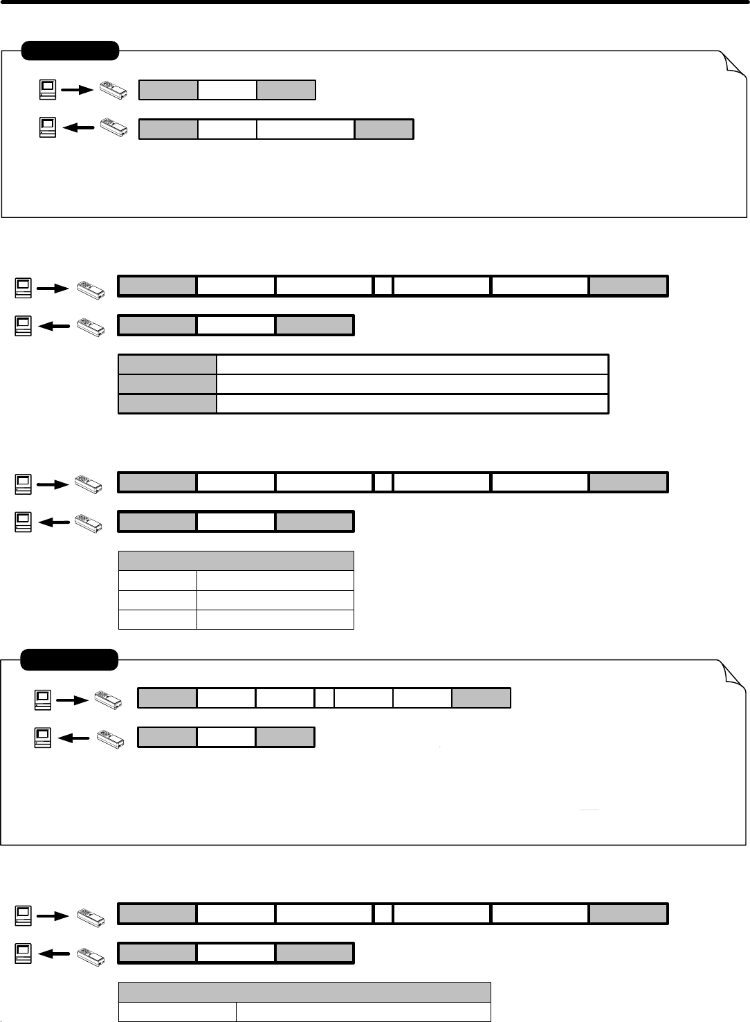
GNET Handshaking
STX CMD CONTENTS CHKSUM CR
GNET PACKET
STX
CMD
CONTENTS
CHKSUM
CR
2 ^B Start of Text 02
STX REPLY CONTENTS CHKSUM CR
ITEM Dec Control Key Function Hex
13 ^M Carriage Return0d
Ascii Ascii Command CodeAscii
Ascii Ascii Contents DataAscii
Ascii Ascii Check SumAscii
REPLY (78) 65 (N) A (Negative) Acknowledge(4e) 41
- 12 -

Communication Protocol
Command Index Table
Reply Index Table
ACK
NAK
Topic Reply
A
N
Reply Information
Contents
See Error Index Table
ACK+Information
Description
NAK+Information
Error Index Table ( For Reply NAK )
ACCESS LEVEL
COMMAND CODE
Topic Error Index
00
01
Access Denied or Password Error
Description
Command packet is too long
DATABASE
FILE
02
03
Command packet is empty
Command code is out of range
04
05
Illegal Command or Data
Database and Register is Empty
06 Record number is out of range
07
08
Check Sum Error
Memory Not Enough
0A File Not Exist
09 Action Failure
Login
Number
-
L
S
F
C
B
P
O
T
E
G
N
SETTING
Topic Command Contents Description
DATABASE
4 Characters for Login(0000)
-
-
Date,Time,Week
-
-
-
New four digit password
-
Read Record by Number
Get Number of Record
Get Date and Time
Set Date,Time and Week
Get Product Version
Set register
Get Register
Set Password
Logout
Erase All Record
- 13 -
Communication Protocol
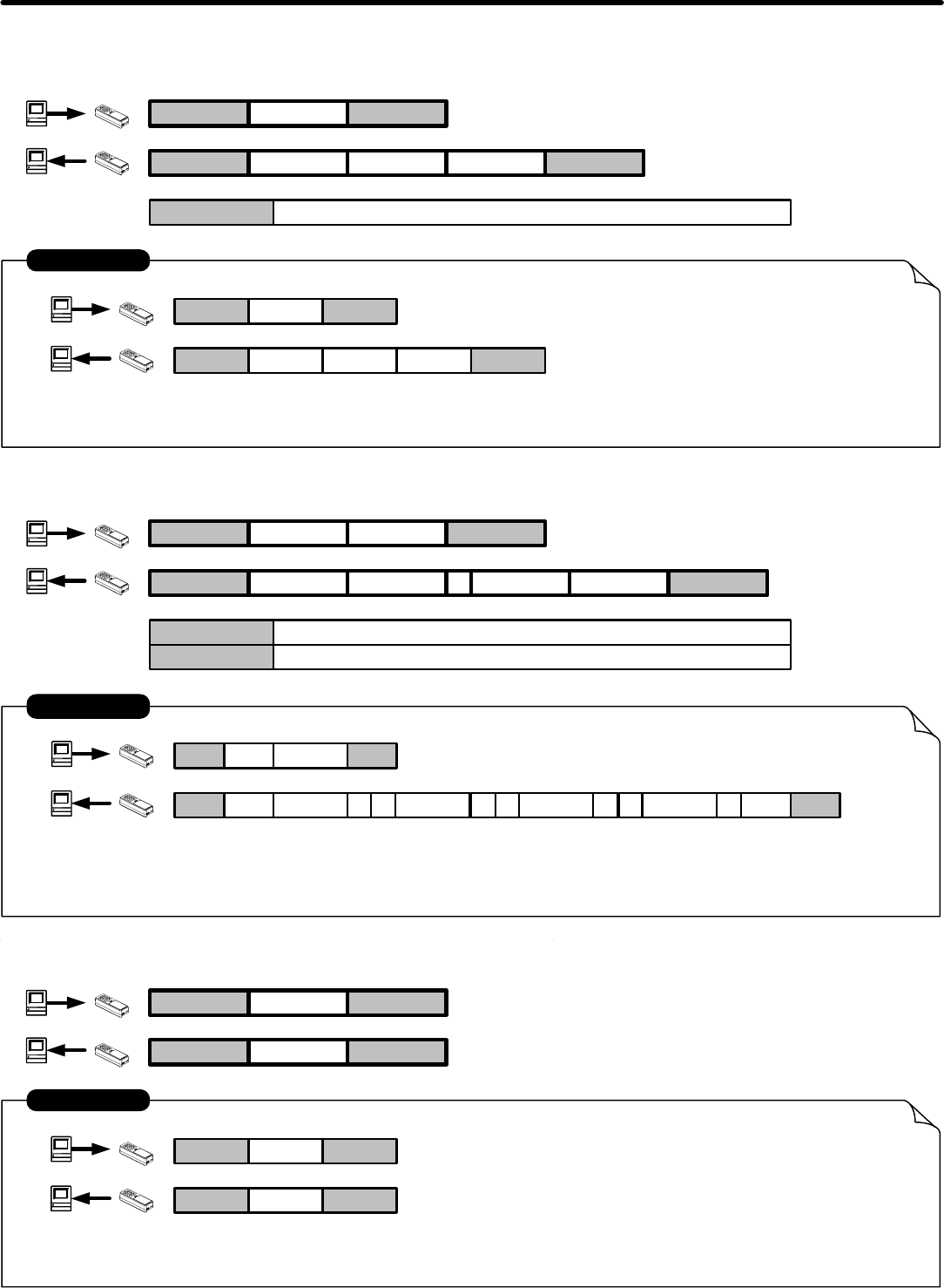
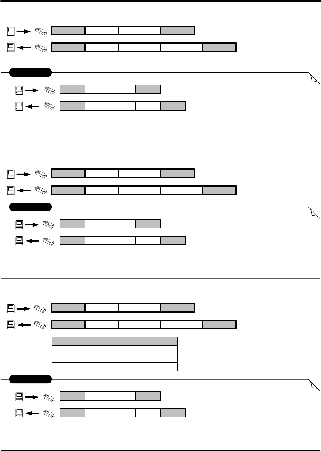
3. ERASE ALL RECORD :
STX ECR
STX ACR
02 E0d
ERASE ALL RECORD
02 A0d
EXAMPLE
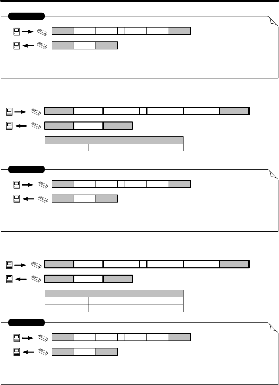
1. GET NUMBER OF RECORD :
STX NCR
STX ACR
02 N0d
The Total of Record Count : 12
02 A0d
EXAMPLE
NUMBER
000C
CHKSUM
NUMBER Record Count . 4 Bytes Width ( 0000h ~ 0080h )
14
2. READ RECORD BY NUMBER :
STX GCR
STX ACR
02 G0d
Read Record Number : 11
TRACK1 ID : ABCD , TRACK2 ID : 2222 , TRACK3 ID : 3333
02 A0d
EXAMPLE
NUMBER
000B
CHKSUM
NUMBER Record Count . 4 Bytes Width ( 0000h ~ 007Fh )
C7
NUMBER
DATA,
DATA Record Data ( TRACK1 , TRACK2 , TRACK3 )
000B
,ABCD
%? ; ?2222 + ?3333
- 14 -
Communication Protocol
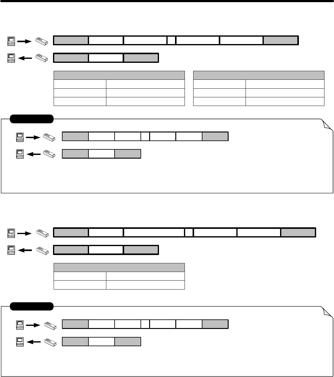
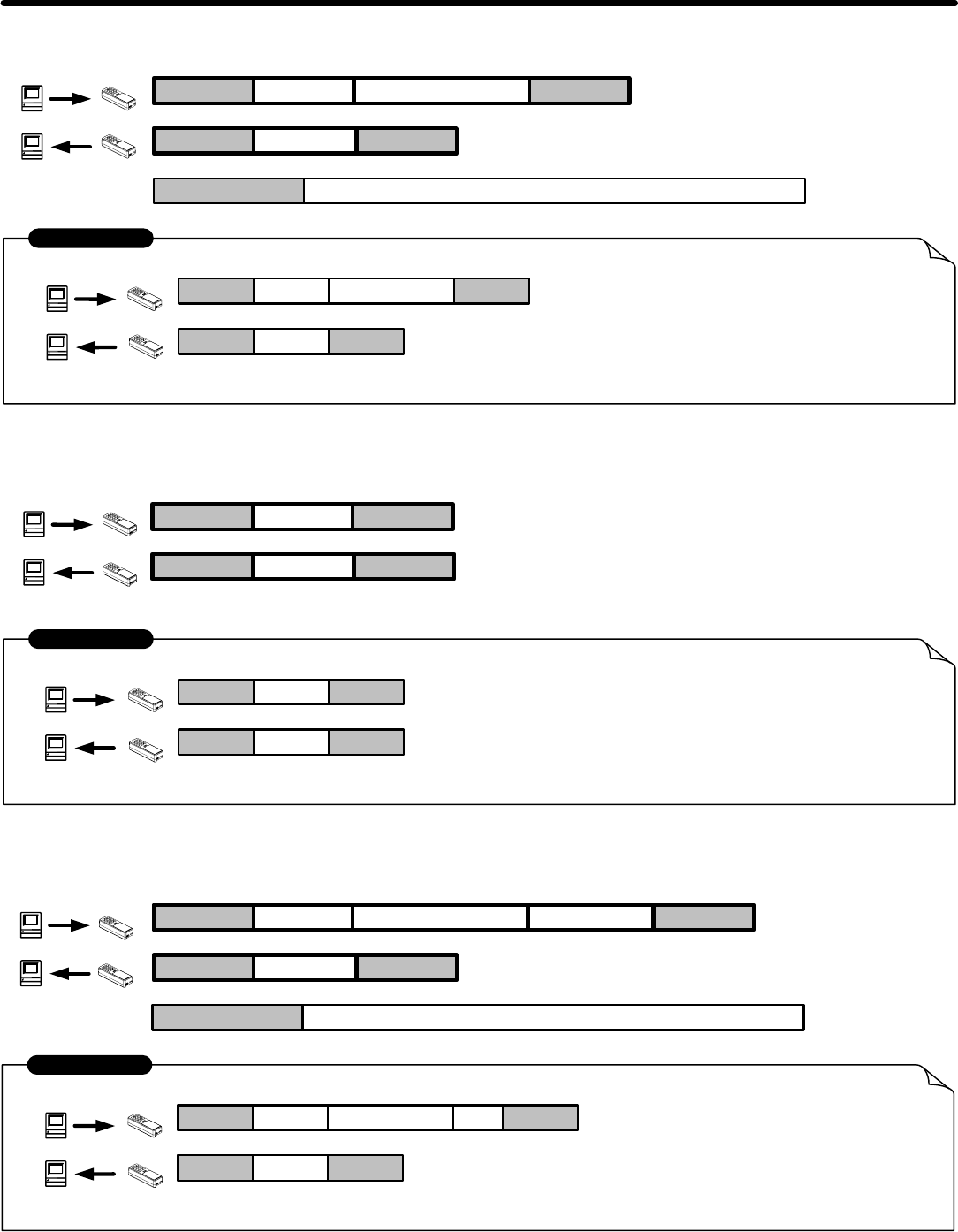
4. SET DATE AND TIME :
STX SCR
STX ACR
02 S0d
Set Date = 2000 / 5 / 5
Set Time = 12 : 30 : 00 , Friday
02 A0d
YYYYMMDDhhmmssw
200005051230006
EXAMPLE
YYYY
MM
DD
hh
mm
ss
5. GET DATE AND TIME:
STX TCR
STX ACR
02 T0d
Get Date : 2000 / 11 / 8
02 A0d
EXAMPLE
Get Time : 14 : 20 : 31 , Wednesday
YYYYMMDDhhmmssw
200011081420314
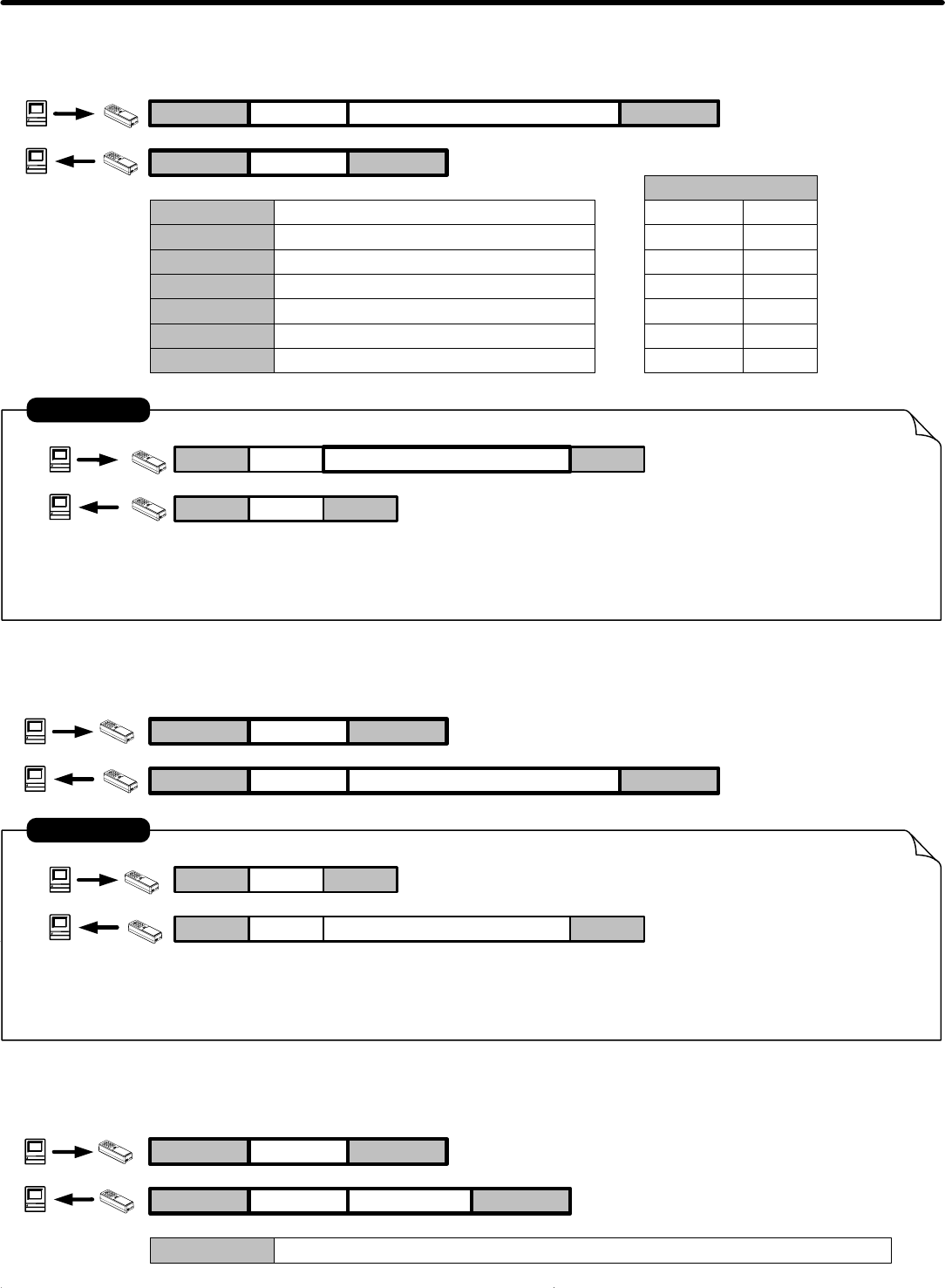
6. GET PRODUCT VERSION :
STX FCR
STX ACR
VxxRmm , Vxx : Firmware Version x.x , Rmm : Modify mm TimesVERSION
VERSION
Year (1980 - 20xx )
Month (01 - 12 )
Date ( 01 - 31 )
Hour ( 00 - 23 )
Mintue ( 00 - 59 )
Second ( 00 - 59 )
WWeek ( 1 - 7 )
Week
SUN
MON
TUE
WED
THU
FRI
SAT
1
2
3
4
5
6
7
- 15 -
Communication Protocol
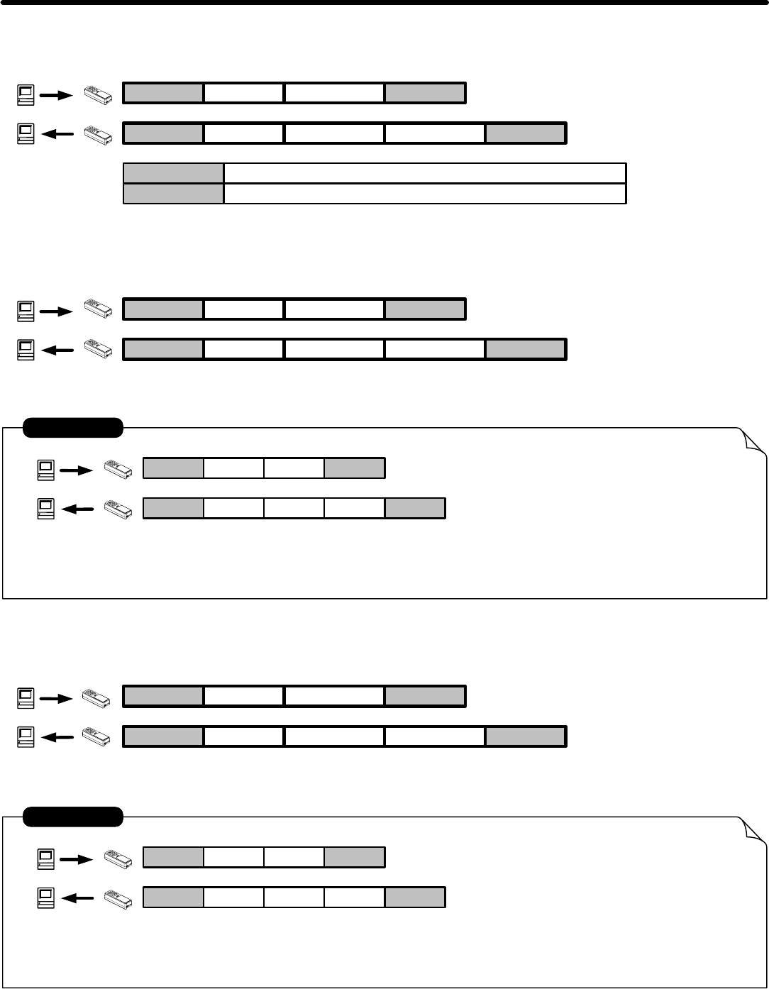
02 F0d
Firmware Version = 1.0
Modify times = 0
02 A0dV1.0R00
EXAMPLE
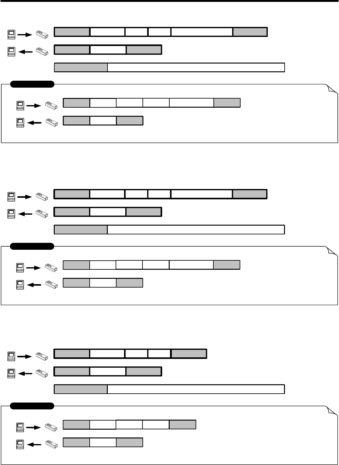
7. SET REGISTER :
STX CCR
STX ACR
REGISTER
REGISTER ,PARAM CHKSUM
PARAM
Register Address . 2 Bytes Width ( 00h ~ FFh )
Set Parameters of Register
7-1. SET POWER MODE :
STX CCR
STX ACR
12 ,MODE CHKSUM
MODE
"00"
"01~FE"
Real Control
Auto Power OFF
02 C0d
Write to Parameter Table Address : 12 h
Set Power Mode : Real Control
CHKSUM= 43h(C) + 31h(1)+ 32h(2) + 2Ch(,) +30h(0) + 30h(0) = 132h
= 33h(3) + 32h(2)
02 A0d
EXAMPLE
12 ,00 32
Modem : 2400
Non- modem : 9600
"FF" Always Power ON
7-2. SET AUTO POWER OFF TIME (LOW BYTE) :
STX CCR
STX ACR
10 ,SECL CHKSUM
SECL
"00-FF" 00h-FFh (0-255)/2 Second
CHKSUM C + REGISTER + , + PARAM
- 16 -
02 C0d
02 A0d
EXAMPLE
10 ,0A 41
Modem : 2400
Non- modem : 9600
Communication Protocol
STX CCR
STX ACR
11 ,SECH CHKSUM
SECH
(00-FF)/2 *256 Seconds
02 C0d
02 A0d
EXAMPLE
11 ,02 33
Modem : 2400
Non- modem : 9600
7-3. SET AUTO POWER OFF TIME (HIGH BYTE) :
Write to Parameter Table Address : 11 h
Auto Power Off Time (High Byte) : 2/2*256 Seconds
Write to Parameter Table Address : 10 h
Auto Power Off Time (Low Byte) : 5 Seconds
"00-FF"
STX CCR
STX ACR
19 ,MODE CHKSUM
MODE
BUZZER OFF
02 C0d
02 A0d
EXAMPLE
19 ,48 45
Modem : 2400
Non- modem : 9600
7-4. SET BUZZER ON/OFF :
Write to Parameter Table Address : 19 h
"FF"
BUZZER ON"xx"
xx : any value
- 17 -
STX CCR
STX ACR
TRACK ,MODE CHKSUM
TRACK
TRACK 1
02 C0d
02 A0d
EXAMPLE
30 ,FF 5E
7-5. SET TRACK ACTIVE MODE :
Write to Parameter Table Address : 30 h
"30"
TRACK2"31"
TRACK ACTIVE MODE : TRACK 1 ENABLE .
Communication Protocol
TRACK3"32"
MODE
ENABLE"FF"
DISABLE"00"
REQUIRED"01"
STX CCR
STX ACR
POWER SAVE ,MODE CHKSUM
02 C0d
02 A0d
EXAMPLE
1E ,FF 71
7-6. SET POWER SAVE MODE :
Write to Parameter Table Address : 1E h
Power Save Mode : Power Save Mode Disable .
MODE
DISABLE"FF"
ENABLE"00~FE"
- 18 -
02 B0d
Write to Parameter Table Address : 12 h
Get Power Mode : Real Control
02 A0d
EXAMPLE
12
00 A1
8. GET REGISTER :
STX BCR
STX ACR
REGSTER
REGSTER
PARAM CHKSUM
PARAM
Register Address . 2 Bytes Width ( 00h ~ FFh )
Set Parameters of Register
8-1. GET POWER MODE :
STX BCR
STX ACR
12
MODE CHKSUM
Same 7-1. SET POWER MODE
Communication Protocol
8-2. GET AUTO POWER OFF TIME (LOW BYTE) :
STX BCR
STX ACR
10
SECL CHKSUM
02 B0d
02 A0d
EXAMPLE
10
0A B2
Get Parameter From Parameter Table Address : 10 h
Auto Power Off Time Period (Low Byte) : 5 Seconds
Same 7-2. SET AUTO POWER OFF TIME (LOW BYTE )
- 19 -
Communication Protocol
STX BCR
STX ACR
11
SECH CHKSUM
02 B0d
02 A0d
EXAMPLE
11
02 A3
8-3. GET AUTO POWER OFF TIME (HIGH BYTE) :
Get Parameter From Parameter Table Address : 11 h
Auto Power Off Time Period (High Byte) : 2*256/2 Seconds
Same 7-3. SET AUTO POWER OFF (HIGH BYTE)
STX BCR
STX ACR
19
SECH CHKSUM
02 B0d
02 A0d
EXAMPLE
19
FF CD
8-4. GET SOUND MODE :
Get Parameter From Parameter Table Address : 19 h
SOUND MODE : ENABLE
STX BCR
STX ACR
TRACK
SECH CHKSUM
02 B0d
02 A0d
EXAMPLE
30
FF CD
8-5. GET TRACK ACTIVE MODE :
Get Parameter From Parameter Table Address : 30 h
TRACK 1 ACTIVE MODE : ENABLE
TRACK
TRACK 1"30"
TRACK2"31"
TRACK3"32"
- 20 -
Communication Protocol
9. LOGIN :
STX LCR
STX ACR
02 L0d
Login password : 0000
02 A0d
EXAMPLE
PASSWORD
PASSWORD 4 Characters for Login. 0000=Initial value
0000
10. LOGOUT :
STX OCR
STX ACR
02 O0d
Logout
02 A0d
EXAMPLE
11. SET PASSWORD :
STX PCR
STX ACR
02 P0d
Set new password : 1234
02 A0d
EXAMPLE
PASSWORD CHKSUM
PASSWORD New four digit password
1234 1A
- 21 -
Communication Protocol
12. GET/SET BLUETOOTH NAME(only workable with cable WAS-T0233)
:
STX KCR
STX ACR
02 K0d
G=GET S=SET
02 A0d
EXAMPLE
NAME
NAME default setting=MINI400
MINI400B
1G/S
1 G
12-1. GET/SET BLUETOOTH PIN CODE(only workable with cable WAS-T0233)
:
STX KCR
STX ACR
02 K0d
G=GET S=SET
02 A0d
EXAMPLE
PIN CODE
NAME default setting=MINI400
1234
2G/S
2 G
12. SET BLUETOOTH PAIR CLEAR(only workable with cable WAS-T0233)
:
STX KCR
STX ACR
02 K0d
S=SET
02 A0d
EXAMPLE
NAME default setting=MINI400
3 S
3 S
Set new PIN CODE : 1234
- 22 -