GLB Electronics SX150EN11C-G Synthesized Network Radio Data Systems, Model SX15 User Manual SNRDS99C
GLB Electronics Inc Synthesized Network Radio Data Systems, Model SX15 SNRDS99C
Synthesized Netlink Radio Data System Operating Manual

GLB ELECTRONICS, INC
Synthesized Netlink Radio Data System
Operating Manual
January 4, 2000
151 North America Drive Tel: 716-675-6740
Buffalo, NY 14224 Fax: 716-675-6742
NOTE: This product is intended for use in a commercial, industrial or business
environment, and not for use by the general public or in the home.
The Synthesized Netlink Radio Data System (SNRDS) is a radio system for transferring digital data between
physical locations where wire connections are impractical or too expensive. It incorporates an intelligent packet
controller, a fast, frequency synthesized data radio, and supporting I/O and indicators. One SNRDS unit, a power
source and antenna is required at each location requiring data communication.
SNRDS communicates with local equipment (a data terminal, host computer, or a specialized hardware device) via
an RS-232 data port. A second serial port is used for outputting special messages or as an addressable serial bus to
add-on modules. 1200 to 19200 baud is available on the link side (over the air).
About This Manual
These instructions are intended to enable the uninitiated to communicate via packet and to describe the SNRDS
thoroughly. Most of these instructions concern the software. It’s assumed that a non-intelligent computer terminal
or a computer having a simple terminal emulator program is available, allowing the operator to access the SNRDS
directly. Basic operation is simple, but the myriad of commands and options provided could be initially
overwhelming; learn the basic commands now and review the list of commands at leisure to develop an
appreciation for the capabilities provided. New commands can be studied in detail as required. Commands are
highlighted in the text (in boldface type) and are often referenced in the discussions. Where a command is
referenced instead of a section number, refer to the command summary in section 7. Commands.
Character conventions used are as follows: CR is a line-feed character, usually a RETURN or ENTER key on a
keyboard. LF is a line-feed, or ^J. Control characters are indicated in the text by preceding the character with “^”,
and are keyed in by holding the control key down while typing the character. All SNRDS commands are in
boldface type. The term “connection” appears in two contexts; one refers to physical connections via electrical
conductors, and the other to a “virtual” connection, which exists only in software. Confusion can be resolved by
assuming that when electrical wiring is the subject, it’s the former context; the latter applies when the only action
involved is in typing characters to the keyboard.

SNRDS Manual GLB Electronics, Inc
0-2GLB Synthesized Netlink Radio Data System
01/04/00
FCC Digital Device or Peripheral - User Notice
Note:
This equipment has been tested and found to comply with the limits for a digital device, pursuant to Part 15 of the
FCC Rules. These limits are designed to provide reasonable protection against harmful interference in a
residential installation. This equipment generates, uses, and can radiate radio frequency energy and, if not
installed and used in accordance with this instruction manual, may cause harmful interference to radio
communications. However there is no guarantee that interference will not occur in a particular application. If this
equipment does cause harmful interference to radio or television reception, which can be determined by turning the
equipment off and on, the user is encouraged to try to correct the interference by one or more of the following
measures:
• reorient or relocate the receiving antenna
• increase the separation between the equipment and the receiver
• connect the equipment into an outlet on a circuit different from that to which the receiver is
connected
• consult the dealer or an experienced TV/Radio technician for help
Warning
Changes or modifications not expressly approved by Aria/ GLB Wireless Data Inc. could void the users authority to
operate the equipment.

1. Table of Contents
1. TABLE OF CONTENTS .............................................................................................................................0-3
1.1. SNRDS APPLICATIONS................................................................................................................................1-1
DESCRIPTION AND FEATURES..............................................................................................................................1-1
HARDWARE FEATURES ........................................................................................................................................1-2
SOFTWARE ..........................................................................................................................................................1-3
PACKET RADIO CHARACTERISTICS.....................................................................................................................1-3
Packet Protocols.............................................................................................................................................1-3
2. INSTALLATION AND CONNECTIONS....................................................................................................2-1
2.1. PHYSICAL MOUNTING ...................................................................................................................................2-1
2.2. PANEL ..........................................................................................................................................................2-1
2.2.1. Main Connector (P1) ............................................................................................................................2-2
2.2.3. Power Supply Requirements .................................................................................................................2-2
2.2.4. Primary Serial Port (COM1).................................................................................................................2-2
2.2.5. Secondary Serial Port (COM2) .............................................................................................................2-3
2.2.6. Other Connections ................................................................................................................................2-3
2.2.7. Antenna Connector (J1)........................................................................................................................2-3
2.2.8. Fuse (F1)..............................................................................................................................................2-4
2.3. INITIAL TESTING ..........................................................................................................................................2-4
2.3.1. Terminal Interface................................................................................................................................2-4
2.3.2. Setting Radio Frequencies....................................................................................................................2-5
2.3.3. Multiple channel selection....................................................................................................................2-6
2.3.4. Initial Link Connection ........................................................................................................................2-6
2.4. TECHNICAL DESCRIPTION ............................................................................................................................2-7
2.4.1. Controller Section.................................................................................................................................2-7
2.4.2. HSM MODEM......................................................................................................................................2-7
2.4.3. Receiver ................................................................................................................................................2-7
2.4.4. Transmitter ...........................................................................................................................................2-7
2.4.5. Panel Interconnect Assembly................................................................................................................2-8
2.5. SPECIFICATIONS ...........................................................................................................................................2-9
3. OPERATION.................................................................................................................................................3-1
3.1. SAVING TO THE EEPROM ...........................................................................................................................3-1
3.2. SYSTEM PLANNING.......................................................................................................................................3-1
3.3. FORWARD ERROR CORRECTION...................................................................................................................3-2
3.4. CONTINUOUS ASCII (CA) MODE .................................................................................................................3-2
4. PACKET OPERATION................................................................................................................................4-1
4.1. ENTERING ADDRESSES ..................................................................................................................................4-1
4.1.1. Local station address.............................................................................................................................4-1
4.1.2. Entering a Destination Address ............................................................................................................4-2
4.2. STATUS REPORT ...........................................................................................................................................4-2
4.3. CONNECTED OPERATION ..............................................................................................................................4-3
4.3.1. Connecting............................................................................................................................................4-3
4.3.2. Chat mode.............................................................................................................................................4-3
4.3.3. Chat Mode special characters...............................................................................................................4-4
4.3.4. Disconnecting .......................................................................................................................................4-5
4.4. UNCONNECTED OPERATION..........................................................................................................................4-5
4.4.1. Unconnected Ack mode ........................................................................................................................4-6
4.4.2. Garbage Mode.......................................................................................................................................4-7

SNRDS Manual GLB Electronics, Inc
0-4GLB Synthesized Netlink Radio Data System
01/04/00
4.5. OPERATION WITH DIGIPEATERS....................................................................................................................4-7
4.5.1. Digipeater Addressing...........................................................................................................................4-7
4.5.2. Status Update with Digipeaters .............................................................................................................4-8
4.5.3. Alternate Digipeater Addressing ...........................................................................................................4-8
4.5.4. Responding to connect requests via digipeaters ....................................................................................4-9
4.5.5. Path address retention and editing........................................................................................................4-9
4.6. OUTPUT FORMAT AND DISPLAYS ..................................................................................................................4-9
4.6.1. Information Fields................................................................................................................................4-9
4.6.2. Header Fields......................................................................................................................................4-10
4.6.3. Status Fields........................................................................................................................................4-10
4.6.4. Display timing.....................................................................................................................................4-10
4.6.5. Chat mode displays .............................................................................................................................4-10
4.6.5.1. Headers in Chat mode.................................................................................................................................. 4-10
4.6.5.2. Information .................................................................................................................................................. 4-10
4.6.5.3. Chat mode status messages.......................................................................................................................... 4-10
4.6.6. Transparent mode displays..................................................................................................................4-11
4.6.7. Command mode displays.....................................................................................................................4-11
4.6.7.1. Headers and tags.......................................................................................................................................... 4-11
4.6.7.2. Information fields......................................................................................................................................... 4-12
4.6.7.3. Status fields.................................................................................................................................................. 4-12
4.7. IMPORTANT CONSTANTS .............................................................................................................................4-12
4.7.1. Preamble length..................................................................................................................................4-12
4.7.2. Number of retries................................................................................................................................4-13
4.7.3. Retry time............................................................................................................................................4-13
4.7.4. Back-off timing...................................................................................................................................4-13
4.8. REMOTE COMMANDS .................................................................................................................................4-13
4.9. UNATTENDED OPERATION...........................................................................................................................4-14
4.9.1. Unattended commands........................................................................................................................4-14
4.9.2. Remote commands, special cases........................................................................................................4-14
4.10. OTHER BASIC COMMANDS .......................................................................................................................4-15
4.11. MONITORING THE COMMUNICATIONS CHANNEL.......................................................................................4-15
4.11.1. Queue mode ......................................................................................................................................4-16
4.12. BEACON OPERATION AND SPECIAL MESSAGES .........................................................................................4-16
4.12.1. Special Message Entry ......................................................................................................................4-16
4.13. BEACON CONTROL ...................................................................................................................................4-17
4.13.1. Alternate Beacon Message................................................................................................................4-17
4.14. STATION FILTERING SYSTEM.....................................................................................................................4-17
4.14.1. Filters and Modes..............................................................................................................................4-17
4.14.2. The Filterlist Mode Command..........................................................................................................4-18
4.14.3. Address entries..................................................................................................................................4-18
4.14.4. Remote control of the filterlist ..........................................................................................................4-20
4.14.5. Additional Notes on the Filterlist......................................................................................................4-21
4.15. UNNUMBERED INFORMATION FRAMES .....................................................................................................4-22
5. LOP PACKET OPERATION.....................................................................................................................5-23
5.1. ENTERING ADDRESSES IN LOP....................................................................................................................5-23
5.2. STATUS REPORT IN LOP.............................................................................................................................5-23
5.3. UNCONNECTED OPERATION .......................................................................................................................5-24
5.4. DIGIPEATERS IN LOP .................................................................................................................................5-24
5.5. CHANNEL MONITORING IN LOP.................................................................................................................5-24
5.6. BEACON MODE IN LOP..............................................................................................................................5-24
5.7. OUTPUT FORMATTING AND DISPLAYS FOR LOP.........................................................................................5-24
5.8. UNATTENDED OPERATION IN LOP .............................................................................................................5-24

SNRDS Manual GLB Electronics, Inc
GLB Synthesized Netlink Radio Data System 0-5
01/04/00
6. HOST COMPUTER SOFTWARE INTERFACING ...................................................................................6-1
6.1. CONNECTED TRANSPARENT MODE...............................................................................................................6-1
6.2. BLOCK MODE...............................................................................................................................................6-2
6.2.1. Block Mode display tags .......................................................................................................................6-3
6.2.2. Information field output .......................................................................................................................6-3
6.2.3. Flow Control.........................................................................................................................................6-3
6.2.4. Sending information .............................................................................................................................6-3
6.2.5. Example of a Block mode transfer to station........................................................................................6-4
6.3. NUMERIC RADIX...........................................................................................................................................6-4
6.4. SPECIAL PACKETS AND PROTOCOLS .............................................................................................................6-5
6.5. MEMORY ALLOCATION................................................................................................................................6-5
6.6. POLLING FOR MESSAGES..............................................................................................................................6-5
6.7. DOWNLOADING CAPABILITY.........................................................................................................................6-5
7. COMMANDS ................................................................................................................................................7-1
7.1. COMMANDS WITH NUMERIC ENTRIES...........................................................................................................7-1
7.2. MODE-SETTING COMMANDS.........................................................................................................................7-1
7.3. COMMAND SUMMARY ..................................................................................................................................7-2
7.3.1. Single-Letter Commands .....................................................................................................................7-2
7.3.2. Commands controlling automatic functions.........................................................................................7-2
7.3.3. Beacon Commands ...............................................................................................................................7-2
7.3.4. Miscellaneous Commands ....................................................................................................................7-3
7.3.5. Diagnostics and Debugging ..................................................................................................................7-3
7.3.6. Other Special Commands......................................................................................................................7-3
7.3.7. Manual functions..................................................................................................................................7-3
7.3.8. Output and Display options...................................................................................................................7-4
7.3.9. Serial Port Setup, m=port (1 or 2).........................................................................................................7-4
7.3.10. Frequency control commands.............................................................................................................7-4
7.3.11. Setup Commands ................................................................................................................................7-5
7.4. COMMAND EXPLANATIONS .........................................................................................................................7-5
8. INDEX ...........................................................................................................................................................8-2

SNRDS Manual GLB Electronics, Inc
GLB Synthesized Netlink Radio Data System 1-1
01/04/00
1.1. SNRDS Applications
The Synthesized Netlink Data Radio System is ideally suited to the transmission of data for a wide range of
applications, such as:
Differential GPS Vehicle tracking
Public Safety Libraries
Banking Remote Telemetry
Security systems Environmental monitoring
Vehicular remote control Military applications
Utilities Oil & gas drilling
Mining Construction equipment
Sports scoring Computer systems
Telephone systems Railway Communications
Oceanography
Supervisory Control And Data Acquisition (SCADA) systems
1.2. Description and Features
The SNRDS easily adapts to a wide range of wireless data transfer applications. In connected mode data is
“packetized”, or broken down to a series of transmissions which are acknowledged as they are received. Hence the
term “Packet Radio”. Connected mode handles the entire communications process automatically, but unconnected
mode has advantages in many applications.
Continuous Asynchronous mode is available as an option. This is a real-time data transfer mode in which asynch
bytes are transmitted immediately as they are supplied. No error checking or protocol is involved, but data is sent
with an absolute minimum of delay. This mode is suited to applications such as remote control of vehicles or
applications in which the protocol is handled entirely by a host computer.
Forward Error Correction is also available for connected or unconnected (not Continuous Asynchronous) modes.
This option provides a great increase in the reliability of reception in the presence of impulse noise or rapid
multipath fading in a mobile environment.
Within a basic communications mode there are several ways in which data is presented to be sent. In Chat mode
ASCII data is typed in, then sent by using a special control character. Block mode is useful for situations where all
byte values occur within the data and the host software can be customized to control the specific operations of the
SNRDS. Transparent mode also allows any byte values but requires no special software in the host.
When not connected, SNRDS displays all channel activity by default, but a series of options control the display by
type of field, connection status or addressing. Field types include headers, status messages, normal information and
special information. If connected-only mode is activated no data is displayed unless a connection is established. A
station-filtering system uses a list of addresses to control the display of received information, based on five different
criteria, such as station of origin, digpeat path and the COM port to be used. This list can also control whether a
connection is allowed or whether a station is to be digipeated.
Messages that are received and acknowledged are queued up in SNRDS if the host isn’t ready to accept them. This
action occurs either if the serial port is flow-controlled by the host or by special command. When a series of
commands are to be given “queue” mode can be invoked, stopping information flow until the user is ready to
receive it. Frames can be displayed one at a time or all at once. SNRDS needs only to be polled periodically to

GLB Electronics, Inc. SNRDS Manual
1-2GLB Synthesized Netlink Radio Data System
01/04/00
access accumulated information. If memory overflows, new data is not accepted from other stations until enough
information has been accepted by the host, releasing sufficient memory space.
Any SNRDS station may be used as a relay point, or “digipeater” to forward packets from other stations which may
be too distant for a direct radio link. Up to 8 digipeaters can be included in an address field to relay packets
through specified stations to the destination if the destination site can’t be reached directly. Watchdog hardware on
SNRDS ensures that the system runs reliably by resetting the CPU automatically in the event that CPU operation is
disrupted. SNRDS also may be remotely controlled via a radio connection.
A message can be stored, to be transmitted automatically to another station each time it connects, or it can be made
to transmit periodically to an independently entered address (beacon mode).
By providing access to the disk operating system (DOS) in the host software, files can be transferred to and from
disk and/or to another station’s disks directly. Appropriate host programming would allow such exchanges to take
place as background tasks, freeing up the host computer to continue other operations transparently to the operator.
Information could be directed to devices such as disk files, printers or other I/O ports.
Two protocols are supported, called MX.25 and LOP (Low Overhead Protocol). MX.25 has more features, but LOP
is simpler and more efficient in many applications. The protocol may be selected by command, but when called
from another station the protocol used by the caller is selected automatically.
The software provides great flexibility, with commands that can be used by the host computer to implement
specialized protocols. Within the HDLC format, any kind of frame can be generated and sent by the host, and the
host can screen received frames and implement custom responses.
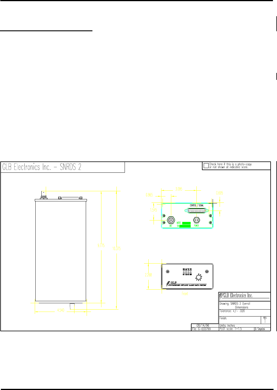
1.3. Hardware features
SNRDS is supplied in an RF-tight aluminum housing measuring 9.775 D by 2.27 H by 4.54 W inches (24.83 x
5.77 x 11.53 cm). All interconnects are on the rear panel and all indicator LED’s are on the front panel. This
arrangement leaves the remaining four surfaces unobstructed.
The on-board controller provides commands for setting the operating frequencies of the receiver and transmitter,
which have independent frequency synthesizers. There are no crystal ovens, so there is no warm-up delay. The
CPU is supported by 64K of memory, non-volatile memory backup and panel display. In the original RDC, a
lithium battery retains the contents of memory when power is removed from SNRDS. The RDC2 and up have non-
volatile memory for storing critical parameters.
There are two hardware “watchdogs” to ensure reliable operation. A CPU watchdog resets the program if the
software should become disrupted. In addition, there’s a limit timer in the transmit keying circuit to limit the
length of any single transmission in case of complete controller failure.
Primary communications with the terminal or computer are carried out via an RS-232 serial port. A secondary
serial port has limited functions at this time, but in future releases of software this second port will become a
separate, fully addressable port such that two RS-232 devices can be connected to one radio. To keep the panel and
installations simple, standard SNRDS bring out all connections except the antenna jack and power input via a
single DB-25S connector. A second RF connector is available for transceivers, providing independent antenna
connections to the receiver and transmitter.
Antenna switching is accomplished with PIN diodes for fast turnaround operation. In packet applications the path
should “turn around”, or go from receive to transmit and vice-versa, very frequently. Slow turnaround time reduces
the link data throughput and increases the probability of collisions. SNRDS radios turn around in 10 milliseconds.
A half-duplex version is also available, which requires no switching and has two RF panel BNC’s, one for the
transmitter and one for the receiver.

SNRDS Manual GLB Electronics, Inc
GLB Synthesized Netlink Radio Data System 1-3
01/04/00
1.4. Software
Written in assembly language, the control program is an independent and unique GLB development. The roots of
the program are based on the original GLB PK1 and PK1L controllers, which have a long history of reliable
operation. Customized versions of the software can be supplied. In most applications it is found that the desired
capabilities already exist, and the application can be developed and tested simply by selecting software options and
setting parameters. Standard software with customized default settings can then be provided for the actual
application. GLB maintains a bulletin board system from which customized EPROM’s can be created and
downloaded. In the RDC2 there’s an on-board EEPROM which stores the parameter settings, addresses, filterlist
entries, modes, etc. In these units the user can customize the software in the field, by making the required settings
by command, then saving the settings in the EEPROM. After that, the system ignores values in EPROM on reset,
using the customized values instead. When modifications require custom software modifications a quotation can be
provided on the basis of programming time.
Customized versions or updates of the firmware can be provided by supplying a new EPROM, or a program image
can be sent via floppy disk or directly by MODEM if facilities are available to program EPROM’s.
1.5. Packet Radio Characteristics
Many SNRDS stations may share a single radio channel, each identified by an “address”. Two stations enter
“connected” mode, in which they ignore all other channel traffic and communicate only with each other. Data may
also be transmitted in unconnected mode, where addressing controls the data path. This mode is useful where the
same data is sent or updated periodically, and an occasional missed packet is not of critical importance. It is also
appropriate where the host computer carries out the task of keeping track of packet re-assembly and error handling
in some other way instead of using the built-in methods.
Packet radio is ideally suited to the transmission of data over a wide range of applications. In connected mode
communications takes place between two specific stations via a “virtual connection”. Once “connected”, other
channel activity is ignored. Data delivery is guaranteed via acknowledgments and a 16-bit error checking
calculation (CRC) ensures that the data was received correctly. Error recover and loss of packets due to noise
bursts, fades, etc. are handled by means of automatic repeats. Packet sequencing guarantees that packetized
segments of files are correctly reassembled at the receiving end. For some applications special protocols may
provide improved performance. For example, in polling applications it might be desirable to eliminate the
overhead of connecting and disconnecting each station to be polled.
Unconnected mode is available for applications where connections are either not necessary or there isn’t time to
make and break them. In this mode the 16-bit CRC is still used, so that flawed transmissions are not displayed. It
works well for applications where information is constantly updated, so that it makes more sense to listen to the
next updated transmission than to repeat a previous one. Addressing can be used to filter which transmissions to
display, such as the source station address(es) or a digipeat path, and if desired data from a specific address can be
sent to the secondary serial port.
Packet Protocols
A “protocol” is an agreed-upon method of forming and sending packets, just as formal procedures are used
between departments in companies. There can be many protocols, but to communicate all stations must use the
same one.
Protocol functions include the digital format of transmissions, methods of synchronization, breaking down
transmitted data into blocks, or “packets”, sending the packets with addressing and control information, packet

GLB Electronics, Inc. SNRDS Manual
1-4GLB Synthesized Netlink Radio Data System
01/04/00
acknowledgments and reconstruction of the data from the received packets. In addition there must be a way to
determine whether a packet has been correctly received and a mechanism to recover missing packets of data when
one or more of the pieces of a file have been received with errors. Certain situations require time delays; while a
protocol may specify the use of a delay, the actual values used vary with the baud rate, channel traffic density and
other factors.
Special protocol functions include automatic repeating, or “digipeating” of packets by other packet stations when
the destination is out of direct range of the source station, sending and interrogation of commands and status
information between packet controllers, etc.
Packet radio operates by establishing a virtual connection between two stations. A connection is requested by
specifying the destination address and giving a command to connect. Once the connection has been acknowledged
(automatically) by the destination station all other channel activity is ignored. Data delivery is guaranteed by a
checking method called a cyclic redundancy check (or CRC) on each transmission. If the error check is correct an
acknowledgment (“ack”, for short) is sent by the receiving station. If no ack is received within a predetermined
time the original data transmission is repeated until acked or until a preset number of tries has been exceeded.
Packet sequencing guarantees that packetized segments of files are correctly reassembled at the receiving end.
The most popular radio protocol, known as “AX.25”, was developed by Amateur Radio operators. Based upon the
X.25 protocol used in wired systems, it adds provisions unique to the radio environment, and in particular, its
adaptation to amateur communications. Many commercial systems use AX.25, and SNRDS uses an extended
proprietary version of AX.25, called “MX.25”, which remains compatible with AX.25 as long as the extensions
aren’t used.
Because it takes time to send acknowledgments, the system doesn’t spend all of its time sending data. In addition,
each packet carries data besides the information to be sent, called overhead. The highest throughput of MX.25 is
approximately 92% of the baud rate, and for LOP it’s about 98%.
SNRDS Manual GLB Electronics, Inc
GLB Synthesized Netlink Radio Data System 2-1
01/04/00
2. Installation and Connections
A SNRDS installation varies with the application, but in general it involves physical mounting, providing for an
antenna and power supply, and connecting the user’s equipment. For new or experimental systems the next step is
to connect a terminal to each station in the system and test the radio path by making connections with the other
units. Once radio paths are proven software operating parameters can be initialized for permanent operation. In
many permanent installations customized firmware avoids the need to set up parameters, addresses and modes of
operation.
2.1. Physical mounting
SNRDS units may simply be placed on any horizontal surface or fastened with screws. Mounting brackets are
available from GLB. Placement should include adequate ventilation and air circulation. High humidity
(condensing conditions) and temperature extremes are to be avoided, to the extent possible. Consideration should
be given to access for testing and maintenance, including a clear view of the panel indicators. In cases where a
terminal is normally not connected, access to the serial port is desirable for test purposes. If the mounting position
makes access to the connectors difficult, extension cables leading out for easy access could be permanently
attached.
2.2. Panel
The panel contains the RF and main connectors and eight indicator lamps. The PR indicator glows continuously
when power is on. The TX LED is off while receiving and on continuously when the transmitter is keyed. An out
of lock condition is indicated if the TE LED is lit. The RX lamp glows continuously in the presence of a RF
carrier signal. The RE LED is lit if the receiver synthesizer is out of lock. The RS LED is lit when a positive

GLB Electronics, Inc. SNRDS Manual
2-2GLB Synthesized Netlink Radio Data System
01/04/00
RS232 state is present on pin 4. The CS LED is lit when a positive RS232 state is present on pin 5. The DA LED
is not used at this time.
2.2.1. Main Connector (P1)
All non-RF connections are made with this connector, simplifying the panel and making the removal and
replacement of the unit easier. A cable is normally made up to separate wires according to the various destinations
of each connection. The table of pin connections is followed by a functional signal description.
pin description pin description
1. Ground 14. Data to SNRDS (secondary port)
2. Data from DTE to SNRDS (primary port) 15. Transmit Clock (secondary port)
3. Data to DTE from SNRDS (primary port) 16. Data from SNRDS (secondary port)
4. RTS to SNRDS from DTE (primary port) 17. Receive Clock (secondary port)
5. CTS from SNRDS to DTE (primary port) 18. Transmitter Keying (active low)
6. DSR from SNRDS to DTE 19. RTS to SRDS (secondary port)
7. Serial Ground 20. DTR from DTE to SNRDS
8. Data Carrier Detect (DCD) 21. Bit 0 of the BCD switch
9. Bit 1 of the BCD switch 22. RS-232 RI
10. /Reset 23. Bit 2 of the BCD switch
11 Not used for RS-232 24. Not used for RS-232
12. Remote Command Lockout 25. Receiver discriminator test point
13. CTS from SNRDS (secondary port)
2.2.2. Power Supply Requirements
SNRDS operates on +12.5 volts DC nominal. Voltage variations within specified limits have no effect on
performance except for power output.
WARNING: Application of reverse polarity to SNRDS could cause extensive internal damage. Be sure
polarity is correct. A safe method of applying power is to connect CHASSIS ground to the power source
negative first, then apply positive power to the connector. A wiring mistake during this test would short
the supply but not put reverse polarity into the SNRDS. If it operates correctly this way connect the leads
permanently.
A separate 2 pin connector is used to supply DC power to the SNRDS. The positive pin is on the right when
viewing the power connector with the key on the bottom The power supply is nominally 12-volts DC, negative
ground. It should be regulated and have a monotonic turn-off and turn-on characteristic; that is, it should be free of
“spikes” or “holes” and should shut down and come up monotonically in order to ensure orderly power-down and
power-up operations. When voltage drops below 7 volts the SNRDS halts and protects the contents of memory.
2.2.3. Primary Serial Port (COM1)
Pins 2, 3, 4, 5, 6 and 7 are used for the primary serial port. These should be cabled into the corresponding pins of a
DB-25S connector for connection to a terminal or computer to send data and commands and to receive incoming
data. It’s fully RS-232C compatible as a DCE (Data Communications Equipment). The other end of the cable
connects to a DTE (Data Terminal Equipment). Connection of SNRDS to another DCE device may be made by
using a null modem cable. Pins 2 and 3 carry the actual data; pin 4 is controlled by the host to control the data
flow from the SNRDS. If data comes in faster than the host can process it, setting this signal false causes SNRDS

SNRDS Manual GLB Electronics, Inc
GLB Synthesized Netlink Radio Data System 2-3
01/04/00
to stop sending. If the host is fast and/or doesn’t do much processing pin 4 may not be needed. This line must be
held positive for data to flow; if flow control isn’t required, connect pin 4 to pin 5.
Pin 5 is controlled by SNRDS to control data flow from the host; the host is expected to stop sending data while
this signal is false. Except in Transparent mode pin 5 may not be needed, since SNRDS can accept any reasonable
input combination at maximum baud rate without overrun
Pin 6, the Data Set Ready signal, is looped back from pin 20, and indicates SNRDS is active and on line.
Pin 20 is the Data Terminal Ready signal from the host. SNRDS feeds this signal to pin 6.
Pin 22 is the RI (Ring Indicator) signal, connected to ground inside SNRDS.
For test purposes or ASCII operation X-on/X-off flow control may be used, requiring connections only to pins 1, 2,
3 and 7. Not all systems use RS-232 connections in the same manner, so some experimentation may be required.
The serial port ground on pin 7 is connected internally to chassis ground.
2.2.4. Secondary Serial Port (COM2)
This port can be assigned to input or output transmitted/received information. CA mode always uses this port, see
3.4. Continuous ASCII (CA) mode. The software also supports data output to this port when a special source
address is entered (see SS). A third use for COM2 is to assign it as a serial bus, used to access up to 256
individually addressable I/O devices. Such devices include parallel input/output ports, D/A and A/D converters,
etc. See FP, FR, FW.
The signals on pins 13, 14, 16 and 19 are the same as the primary port, and the signals meet the RS-232D
standards for voltage levels. Pin 17 outputs the serial clock, used for synchronization with serial bus devices.
2.2.5. Other Connections
Pin 12 is the Remote Command Lockout connection (See AQ and DL commands). When this signal is at 0 volts
remote commands are accepted, and when at +5 volts remote commands are rejected. This input allows remote
command access to be controlled via an external device or condition.
Pin 17 is the serial clock for the secondary serial port.
Pin 25 is connected to the receiver discriminator output, to be used as a test point to observe received signals. It’s
DC coupled and non-filtered.
2.2.6. Antenna Connector (J1)
The standard RF connector is a female type BNC. Allow enough clearance so the coax cable doesn’t have to make
a sharp bend. Right angle adapters may help to avoid undue stresses on the cable and its connector.
SNRDS is designed for a nominal antenna impedance of 50 ohms. The selection, mounting and physical
positioning of the antenna is dependent upon the distance and direction to other stations in the system, and other
factors such as the noise environment and frequency of operation. Line-of-sight radio paths are desirable for
reliability and are necessary to cover long distances. Directional antennas are useful to increase the distance over
which communications are possible, and can be helpful in rejecting interference or noise.

GLB Electronics, Inc. SNRDS Manual
2-4GLB Synthesized Netlink Radio Data System
01/04/00
Duplex units are available, having two BNC connectors instead of one.
2.2.7. Fuse (F1)
The fuse is a self resetting type. It is rated for 3 amps for the 5 watt units. The fuse can blow due to component
failure or if reverse polarity is applied to the unit. Although a protective diode forces the fuse to blow in this case,
circuit damage could still occur. 25 watt units have a 10 amp AGC fuse. This is accessible at the fuse holder in
the power amp cover.
2.3. Initial Testing
There are three major components to connect; a power supply, a terminal and an antenna. It’s a good idea to
connect the antenna (or a dummy load) first, to avoid transmitter operation without a load. The terminal device
may be either an ASCII terminal or a computer using a terminal program. Most telephone MODEM programs
have a mode allowing terminal operation. When the power supply and terminal are connected to the SNRDS a
preliminary test can be made. No warm-up time is required.
2.3.1. Terminal Interface
The first step is to achieve communications with the SNRDS via the serial port. The terminal (or computer with a
MODEM program) should be set to send and receive 8 bits, no parity, and one stop bit (unless another combination
has been specified in the order). The number of stop bits is important; if mismatched it may work fine for testing
by hand typing, but fail when data is transferred at high speed.
The standard SNRDS software is Unconnected Transparent mode. To get the unit into command mode requires
the typing of a special character sequence. The default character sequence is three capital letter “U” and only three
within 1 second. It is very important that no characters are typed for a ¼ second before and ¼ second after the
three capital letter “U”. This timing is required so that you can send three capital U in your data stream without
going into command mode. It is also, very important that the serial parameters of the terminal program are set the
same as the SNRDS. The serial parameters for the SNRDS can be found on the “Firmware Settings Report” that is
shipped with each unit. A colon prompt (“:”) should be displayed by the SNRDS meaning that it is in command
mode. A full sign-on message can be obtained at any time by typing RETURN by itself at the prompt.
GLB SNRDS w Vx.xx,
A letter will appear at “w” only if the SNRDS incorporates an installed option; F would signify Forward Error
Correction, C would signify a CA Mode unit, etc. Lack of a letter here indicates the unit is a standard SNRDS. V
stands for Version, x.xx would be replaced by the software version number.
If nothing happens or if a garbled character stream appears, repeat the procedure. A garbled sign-on may mean it’s
somehow missing the correct baud rate. SNRDS software is optionally supplied with a fixed baud rate instead of
autobaud, identifiable in that the command prompt “:” occurs without waiting for the RETURN character. If this
could be the case and the preset baud rate is unknown, try setting the terminal rate to different baud rates until the
message clears up. If the message doesn’t appear review the connections - there’s an incompatibility somewhere.
NOTE: If communication can be established with the unit but the display isn’t entirely correct (or if commands are
not accepted correctly), see P commands for setting up the serial ports. Also check ON and OW.
When a sign-on comes up, try entering an S followed by RETURN. The terminal should display:

SNRDS Manual GLB Electronics, Inc
GLB Synthesized Netlink Radio Data System 2-5
01/04/00
1 /ABCDEF 0 /------ 0/ //LDU/XE/RL/0
(the customized address replaces the “ABCDEF”)
Differences in this status display may be due to customized default settings in the EPROM, or in RDC2’s, the
EEPROM. If a message similar to this is obtained proceed to the next section. Make certain the terminal being
used is able to accept characters as fast as the SNRDS sends them. The SNRDS always uses CTS/RTS flow control,
so if the terminal respects it overflow won’t occur. Alternatively, if the terminal uses Xon/Xoff flow control, the
command OXE will invoke that form of flow control in the SNRDS. Note that Xon/Xoff isn’t suitable for
non-ASCII data transfers.
2.3.2. Setting Radio Frequencies
If the frequency settings in the EPROM supplied with SNRDS have been customized, the transceiver is already set
to the default frequency. If not, any frequencies stored in the EEPROM are used. Values in the EEPROM are
checksummed, and if the checksum should be incorrect those values are abandoned in favor of the EPROM. Values
in the EEPROM can be changed by the user at any time (See DU and DOC commands).
Frequency control software is written for flexibility on different RF sections, requiring a few preliminary entries:
channel step spacing (RS), intermediate frequency (RI) and synthesizer divide modulus (RM). Since calculations
are performed on each entry to check consistency, a channel spacing value must be present before SNRDS will
allow any other entries. Note that these settings are mandated by the particular radio section being used, and values
are supplied in the EPROM to match the hardware for any particular SNRDS. The following examples are shown
for reference only.
All frequencies are entered in kilohertz to the nearest ½ kilohertz and the commands must be terminated with a CR
(RD, RM and RN don’t represent frequencies, so they work like other SNRDS commands). Channel selection
must be consistent with channel spacing; that is, any selected frequency must be a multiple of the reference
frequency selected with RS. It also must be within range limits or the entry is ignored and an error is indicated. For
example, to set channel step spacing to 10 KHz:
rs 0-10
As usual, “ 0-“ is sent by the controller to show the previous value. Next, check the receiver synthesizer modulus;
this is set to 64 for radios below 250 MHz and 128 at higher frequencies. Set it to 64:
rm 128-64<CR>
The receiver IF is a signed value, where a negative value indicates that the local oscillator is on the low side of the
signal frequency and a positive value indicates it’s on the high side. Below 160 MHz the IF in SNRDS is +21400
KHz:
ri 0-21400<CR>
^
This ‘-‘ isn’t a minus sign; it’s the usual prompt for input sent by SNRDS in response to a command
The remaining commands may be changed by the user. The first two entries set the range limits for entered
frequencies, RL and RU, for Lower and Upper limit, respectively. These limits offer some measure of protection
against accidental operation on unauthorized frequencies. Before any channel frequency command is accepted, the
requested frequency is compared to these limits; if out of range an error is indicated and the frequency isn’t
accepted. Assuming the allowable limits to be 155 and 157.35 MHz:
rl 150000-155000<CR>

GLB Electronics, Inc. SNRDS Manual
2-6GLB Synthesized Netlink Radio Data System
01/04/00
ru 174000-157350<CR>
Next, a receiver channel is entered:
rr 150000-155030<CR>
And a transmitter channel:
rt 150000-155030<CR>
There’s one other variable involved if the receiver and transmitter operate on the same frequency: RO, for
transmitter Offset. SNRDS transmitter synthesizers operate continuously, even in receive mode. The presence of
this on-channel signal at close proximity to the receiver (inside the housing) would cause interference to received
signals. To avoid this problem the transmitter is shifted to a nearby frequency just far enough to avoid interference;
when the transmitter is keyed it’s simultaneously shifted back to the actual transmitted frequency. The reason for
this strategy is that it takes less time to shift the transmitter a small amount than to lock it from scratch each time
it’s keyed, resulting in faster turnaround time. RO accepts a signed value such as “-30” to shift the transmitter 30
KHz lower during receive operation. The best offset to use is normally preset in the EPROM default values, so this
command is described mainly for reference purposes
ro 0--30
^
Here we really do have a minus sign!
2.3.3. Multiple channel selection
A software option is available for storing and receiving multiple frequency channels. The RC command is added
for channel selection, and optionally, a channel switch can be provided that allows panel selection of these
predetermined frequencies. Frequencies are entered independently by selecting a channel, then entering them with
RR or RT, in the normal way.
Default frequencies can be supplied with the order, so that a set of initial frequencies is automatically filled in on
reset. The number of channels must be specified when ordered. With the switch option the maximum number of
channels is 8 channels, but there is no (reasonable) limit when selection is done using the RC command.
2.3.4. Initial Link Connection
Pick one of the SNRDS’s with its associated terminal as the “local” station and the other as the “remote” station.
We’ll assume that the operating frequencies are set and that the software isn’t customized (except for the station
address). The default settings of the SNRDS are for Unconnected Transparent mode. In this mode as soon as a key
is typed at the keyboard it is transmitted by the SNRDS. The receiving radio should then receive this character and
display it on the terminal. It is very important that the RTS and CTS pins (pins 4 and 5 on the SNRDS) are
connected to the terminal and that hardware flow control is enabled. The SNRDS requires hardware flow control
and will not display any data unless it is used. If the user equipment does not have hardware flow control then pins
4 and 5 on the SNRDS DB25 connector must be jumpered together.
When bench testing use shielded loads and place the SNRDS units as far apart as possible to avoid receiver
overdrive. Unless the dummy load or coax is leaky a few feet should be sufficient. If antennas are used for testing,
they should be separated as far as possible.

SNRDS Manual GLB Electronics, Inc
GLB Synthesized Netlink Radio Data System 2-7
01/04/00
Weak signals are caused by poor antenna installations, less than ideal topography between the stations or simply
because the stations are too far apart. It’s possible, although unlikely, that test signals could be noisy if double
shielded coax is used and the loads are really RF-tight. P1 pin 25 carries the receiver discriminator output signal.
Connect it to an oscilloscope and observe the received signal while sending data from the other unit. Noise will be
seen when no signal is being transmitted, but during transmissions a clean data waveform should be visible with
little or no noise.
2.4. Technical Description
SNRDS consists of four subassemblies; A Radio Data Controller (RDC), a radio receiver and transmitter, and a
interconnect board.
2.4.1. Controller Section
The RDC consists of a 64180 microprocessor with 32K bytes of EPROM and 32K bytes of CMOS RAM, an GMSK
radio MODEM, and a parallel input/output port. The 64180 has two internal asynchronous serial ports. Both the
primary and secondary port outputs through an RS-232 driver chip for bipolar drive levels. The parallel port is
used to control the radio and MODEM sections. A lithium battery provides standby memory back-up in older
RDC’s. The RDC II and up have non-volatile storage for operating parameters, and they don’t have the lithium
cell.
2.4.2. GMSK MODEM
The purpose of the MODEM is to condition the digital data stream generated by the controller into a form that can
be transmitted via the radio section, as well as to recover the transmitted signal from another station and convert it
back to digital data. It modulates the transmitter to generate a frequency shift keyed signal, but conditions the state
sequence of the carrier so as to limit the required base bandpass of the radio. A 3-pole low pass filter limits the
transmitted bandwidth by attenuating modulation components above 5 KHz. No scramblers or de-scramblers are
required. The GMSK may be operated from 4800 - 19200 baud, with some parts values changes and switch
selection.
2.4.3. Receiver
The receiver has its own frequency synthesizer, controlled by a serial data stream from the controller assembly. It
features four helical resonators in the front-end, an RF amplifier, a double balanced mixer, and a 21.4 MHz IF
amplifier with a bandpass crystal filter. A second mixer results in an IF of 455 KHz, where a ceramic bandpass
filter supplements the selectivity provided in the first IF. The limiter/discriminator output is filtered in an active
low-pass filter and fed to the MODEM section.
2.4.4. Transmitter
The transmitter has its own frequency synthesizer, controlled by a serial data stream from the controller assembly.
The synthesizer VCO outputs directly at the operating frequency, which is then amplified to the required system
power output level and low-pass filtered for harmonic rejection. Antenna T/R switching is implemented with PIN
diodes. The receiver antenna connection plugs into the transmitter assembly, at the receiver port of the switch.
Two-point modulation is used to produce DC modulation response. The upper modulation frequency limit is
constrained by the modem filter. An interlock prevents transmitter keying if the synthesizer isn’t locked.

GLB Electronics, Inc. SNRDS Manual
2-8GLB Synthesized Netlink Radio Data System
01/04/00
2.4.5. Interconnect Assembly
All non-RF interconnections are made on this assembly. The panel indicators and their drive circuitry and the
power fuse are also on this board. The system connector is RFI filtered.

SNRDS Manual GLB Electronics, Inc
GLB Synthesized Netlink Radio Data System 2-9
01/04/00
2.5. Specifications
Since there are many frequency and power levels for SNRDS units the following is shown as typical for the 450-
470 MHz, 4-watt unit. Detailed specifications are available for any particular unit.
System
Temperature range: -30 to +60 degrees C, no warm-up time
Humidity: 0 to 99% RH, non-condensing
Size: 7.675W x 2H x 6.3L inches, (cm)
Weight: 2.25 lbs. (kilograms)
Power requirement: 10-15 volts DC, negative ground
Current drain: 300 mA receive, 1200 mA transmit
Controller RDC2 or RDC$
MODEM built in, optional rates
Data rate, link side: MODEM dependent; 1200 to 9600 baud
Data rate, serial port:300, 600, 1200, 2400, 4800, 9600, 19200 baud
CPU Watchdog timer: Approximately 1 second
Transmit limit timer: approximately 15 seconds
RAM 32K bytes
EPROM 32K bytes
EEPROM 512 bytes
System turnaround time 3 ms typical receive-transmit, 5 ms transmit-receive
Radio MIN TYP MAX UNITS, COMMENTS
Frequency range available from 130 to 950 MHz. Specifications vary with frequency, shown here for the 450-
470 MHz band
Range with retuning 450 --- 470 MHz
Range without retuning 5--- --- MHz
Antenna impedance --- 50 --- Ohms nominal
Frequency stability --- --- ±2.5 PPM full temp
Synthesizer resolution 12.5 kHz
Channel spacing 25 kHz
Operating temperature -30 --- +60 Degrees Celsius
Duty cycle 100%
Current drain, standby --- --- 150 mA max, receive
Current drain, transmit --- --- 1A
Conducted spurious --- --- -57 dBm (regulatory limit)
Transmitter
Output power 4 5 --- Watts into 50 ohms @ 13.8 Vdc
Conducted spurious/harmonics --- --- -53 dBc keyed (regulatory limit)
Key-up time to stable data 3 5 ms
Receiver
Sensitivity --- -120 -119 dBm 12 dB SINAD non pre-emphasized
Spurious & Image rej 70 --- --- dB
Adjacent channel rejection 70 --- --- dB @ ±25 Khz
Intermodulation 65 70 --- dB, third order

GLB Electronics, Inc. SNRDS Manual
2-10 GLB Synthesized Netlink Radio Data System
01/04/00
Frequency response DC 5000 Hz
SNRDS Manual GLB Electronics, Inc
GLB Synthesized Netlink Radio Data System 3-1
01/04/00
3. Operation
In this section, control keys on the terminal are identified as “^J” for Control-J, etc. “CR” refers to a carriage
return character (marked RETURN or ENTER on most keyboards). Sometimes a required input is shown in <>
instead of quotes, where additional quotes could confuse matters. “LF” is short for LINE FEED (^J on keyboards
lacking a LF), “Ack” is short for “Acknowledgment”, and “Info” is short for “Information” (The term “data” is
more general and includes data transmitted and used internally between stations to expedite protocol operation).
3.1. Saving to the EEPROM
In the course of configuring the system for the application there will be mode and parameter changes, which are
stored in tables. For example the station address is usually different for each station in a network. When the system
initializes, such values are checked at several levels. First, the EEPROM is checked, and if its contents show a
good checksum table values are taken from it. If not, the tables in the EPROM itself are used.
All table values can be changed by command, and these changes take place in RAM memory. Therefore if the
system is reset or power goes off they are lost. In order to make changes permanent the tables are stored to the
EEPROM. The EEPROM contents are protected in hardware, so in order to save new information it must first be
unprotected. Two commands are involved; DU and DOC.
The DU command is to Unprotect the EEPROM in preparation for writing, and DOC does the writing.. In order to
minimize the chance of writing to the EEPROM accidentally, this command is canceled on any following
command. Thus, the DU command must immediately precede the write command. It is very important that a CR is
not type after either of these commands. Just type the command and do not type anything else until the colon
prompt is displayed. See the command explanations for more detail.
3.2. System Planning.
Since there are a large number of modes and options, your system objectives provide the best starting point. Look
over the following examples to see what approach might best achieve those objectives.
First decide whether you need connected mode. Connected operation is characterized as follows:
1. An address must be specified and a connect request commanded before each data transfer.
2. Data is transferred point-to-point between two stations only. Other channel activity is ignored.
3. When transfers are complete a disconnect operation must be commanded.
4. Data size is unlimited.
5. Data transferred in connected mode has guaranteed integrity. Repeats are made as necessary and the
data is packetized and reassembled in the correct order.
Examples of use: file transfers, where large amounts of info must be sent from one station to another, or dedicated
point-to-point circuits where the stations can remain connected continuously.
Unconnected mode may be better where many stations are being polled and data fields are short, because it saves
the time otherwise taken for connecting and disconnecting. It might also be better when the data being sent is
volatile, that is, it’s being updated repeatedly with new values. In this case it might take less time simply to send an
updated version of the data, rather than to persist in repeating the original data until acked. Depending on how
often it is to be updated, there may be time to send each message more than once in unconnected mode, improving
the chances that each message is received. In unconnected mode:

GLB Electronics, Inc. SNRDS Manual
3-2GLB Synthesized Netlink Radio Data System
01/04/00
1. No address need be specified, but addresses can be used to limit which stations receive the messages
using the filterlist (section 4.14.2. The Filterlist Mode Command)
2. Connect/disconnect requests aren’t used.
3. The maximum length of the data is 256 bytes per frame, but if it’s longer, additional frames are
automatically generated to send the excess, up to 7 frames at a time.
4. No acknowledgments are made, so delivery isn’t guaranteed.
5. Each message is sent n times, although n is normally set to 1.
If multiple frames are needed to send the data, it’s possible for one or more of them to be lost, resulting in an
incomplete message.
There’s an intermediate system between connected and unconnected mode, called unconnected acknowledgment
mode. In this case the data is sent N times (specified in advance) to a specific station address. When received, the
data is acknowledged and further repeats are halted. This method eliminates the need to connect/disconnect. If
more than one frame is sent (because the message exceeds 256 bytes) there is a separate acknowledgment for each
frame. It is up to the user’s software to determine which frames have been acknowledged, since in this mode the
controller doesn’t number the frames.
Applications: GPS differential correction, SCADA systems.
3.3. Forward Error Correction
This feature may be ordered as a software option. When FEC is used, extra correction bits are sent with the data
that are used to correct errors which might have occurred during transmission. Although the extra bits incur some
overhead, the probability of receiving any given frame is greatly enhanced, particularly in the presence of impulse
noise or rapid fading, such as in moving vehicles.
FEC must be used in all stations of a system, since transmissions are not possible between FEC and non-FEC
stations. Most modes and commands operate in the same manner with or without FEC, but a few of the commands
differ.
Applications: GPS, SCADA, connected mode applications in noisy locations or fading paths.
3.4. Continuous ASCII (CA) mode
For real-time applications or in cases where no protocol is required in the SNRDS unit, and all that is required is
for the controller to transfer bytes via radio as received, this mode is available as a software/hardware option. This
mode operates in 2 ways. The first is the transmitter can be keyed by setting the secondary RTS true. While the
transmitter is keyed bytes are sent as they are entered at the secondary serial port. The first bytes of data will be
buffered until the radio has finished sending its’ preamble. They’re displayed at the receiver end as received. The
entire transmission does not have to be received before data starts to be displayed. There is no addressing or error
checking. The host system must perform those functions as required.
The second method of operation of CA mode is the transmitter is keyed automatically on the receipt of the first
byte of data into the secondary serial port. This makes the SNRDS completely transparent to the user equipment
since no transmitter keying signal is required. This method is more popular than the former since this method
allows the radios to most closely emulate a wire in both function and timing.
CA mode has recently been modified such that garbage characters are suppressed at the beginning and end of the
transmission. This change allows the user to get accurate data the first time. The user no longer has to sift through

SNRDS Manual GLB Electronics, Inc
GLB Synthesized Netlink Radio Data System 3-3
01/04/00
the data to find where the good data starts and ends. This addition does not remove the possibility of erred data, but
dramatically reduces the incidences of erred bytes.
CA mode uses both serial ports of the radio. Both serial ports are located on the signal DB25 connector. Special
cabling is available from GLB. The Primary serial port is always in command mode. Commands can be changed at
any time, but should not be changed while data is being transferred since errors may occur. The Secondary serial
port is used only for serial data transmission and reception.
Normally, CA mode operation calls for a serial port baud rate that is the same as the link (radio side) baud rate, but
the rules can be bent because of the intelligence in the controller. Although the average baud rate coming into the
primary serial port from the host must not exceed the link baud rate of the radio, the internal buffering allows
higher speed bursts. Thus it is possible to use 19200 baud between the host and controller, even if the controller
sends only 9600 baud on the link side. If bytes are sent half of the time on the average, overrun will not occur. If
overrun should occur, the controller CTS signal is set false, signaling the host to wait. Similarly, at the receive end
if the link rate is 9600 baud and the transfer from the controller is only 4800 baud, receive buffering prevents loss
of bytes (although a delay would accumulate on received bytes that go into the queue until they can be displayed).
CA mode requires a completely different EPROM firmware and different cabling. It is not compatible with any of
the packet protocol software and will not communicate with it.
Applications: vehicular control, SDLC-mediated systems, where the host manages the protocol.

SNRDS Manual GLB Electronics, Inc
GLB Synthesized Netlink Radio Data System 4-1
01/04/00
4. Packet Operation
This section describes how to operate using the MX.25 protocol. LOP operation is very similar; the differences are
discussed in section 5. LOP Packet Operation. It’s assumed that the controller is interfaced and functional. When
a CR is typed, a sign-on message appears:
“GLB SNRDS-2 V1.99Q”
“V1.99Q” is the software version number, which will vary.
Whenever a “:” appears, either by itself or at the end of the sign-on message, command mode operation is
indicated. It’s displayed after completion of any command, as long as control remains in the command mode. If an
error occurs in any command the “:” is replaced by a “?”, but in either case it’s ready to accept another command.
The controller comes up in the “monitor” mode, in which it displays all packet activity on the radio channel, and
with MX.25 protocol selected.
4.1. Entering addresses
When using connected mode or unconnected ack mode it is necessary to assign a unique address to each station in
the network. Addresses are also useful in unconnected mode, since the addresses can be used to control the display
of information. In MX.25 protocol each packet contains the station address and the address of the destination
station. Both addresses are added automatically to each packet in both unconnected and connected modes, but that
information must be initially supplied by the user.
An MX.25 address consists of two parts. The first, or base address, consists of 1 to 6 characters, which may be
A-Z, 0-9 or “/”. The second part is a numeric value in the range 0-15. This added number, called a “Secondary
Station IDentifier”, or “SSID”, makes it possible to operate more than one station under the same address without
confusion. For example, there might be one or more digipeaters plus a primary station using the same base address.
These stations may be distinguished by using a different SSID value on each address. It’s customary to use 0 for
the first or primary station, and an SSID of 15 is reserved as “wild” - if the correct SSID isn’t known by another
station the operator may use the value 15 to make an initial connection.
4.1.1. Local station address
The station address identifies the station being accessed. A default address is copied out of the EPROM at
initialization. If it needs to be checked or changed, use the SC (Set Call) command:
SC<station address>
The existing address is then displayed:
Type: “SC” (the controller then displays “ABCDEF-“);
If a new address is typed in response it replaces the old entry. Type a space instead, and the old one remains
unchanged. Next the SSID value is displayed:
“0-“.

GLB Electronics, Inc. SNRDS Manual
4-2GLB Synthesized Netlink Radio Data System
01/04/00
Type another space to exit the command. Re-enter “SC”, and this time type a new address. Enter a space or a dash
after the last letter. Lower case letters are automatically promoted to upper case.
At this point the controller displays “0-“, prompting for the entry of the station SSID, and showing that the value
now in effect is “0”. If “0” is satisfactory, type a space to retain it. If not, enter another value, followed by a space.
Repeat the command with spaces to confirm that the new address is now in place. The station address stays in
place until changed or a bad checksum is found when the controller is reset.
4.1.2. Entering a Destination Address
There are two methods for entering the destination address.
Method 1: The SD command, following the same rules as the SC command as explained in the previous section.
Method 2: The command “C” and the destination/path may be typed in a single line, as in the following example:
C REMOTE<CR> calls REMOTE-0
C<CR> connects to previously entered path
Note that an SSID of 0 is assumed if none is entered. To enter an SSID it must be prefixed with a hyphen,
immediately after the address (no spaces). While typing the command backspace may be used to correct errors, and
^R to retype the line. When the <CR> is typed a connect sequence is started.
Digipeaters may also be specified with the C command, optionally using the letter “V” followed by the digipeater
addresses after the destination address. See section 4.5., “Operation with digipeaters”. Whenever new addresses are
typed in conjunction with the C and V commands the stored addresses entered with SD and SV, respectively, are
changed.
The destination station address and any digipeater address change only when retyped or if a connection is received
from a different station. If a connection is received the destination address and digipeater addresses (called a
“path”) are changed to match the new station automatically.
4.2. Status Report
The command S<CR> produces an abbreviated “report” showing the addresses in effect, the current operating
state, and what modes are currently in effect. Type:
S<CR> The response is: “1 /TEST 0 /------ 0 / //LDU/XE/RL/0”
The display line is separated into nine “fields”, separated by “/”s. The first field is the link “state”, and the “1”
indicates that the station is currently disconnected. The second field is the station address and SSID, the third is
the destination station’s address and SSID (here none is entered), and the remaining fields designate various mode
settings. See section 7.5. for a complete description of the “S” command.
At this point the only concern is with the addresses and “state”. The state is an internally generated number
representing conditions on the link connection. The most significant thing to know is that a state of 1 means
disconnected, and anything above 4 indicates a connected state. States 2-4 occur during connect/disconnect
processes. Other values that occur are used mainly for diagnostic purposes.
To obtain a complete listing of mode commands that are enabled, type “S1”.

SNRDS Manual GLB Electronics, Inc
GLB Synthesized Netlink Radio Data System 4-3
01/04/00
4.3. Connected operation
Connected operation is always used to obtain the maximum benefits from packet operation. It always involves
exactly two stations. Stations in connected mode ordinarily ignore all other station activity on the radio channel,
and won’t respond to a connect request by any others. All information in connected mode has guaranteed delivery.
In case of error in transmission packets are not accepted, and the transmission is repeated. Messages are not
displayed more than once, even if they have been repeated by the sender to obtain an acknowledgment. Packets
being sent are not deleted from the sender’s buffer until an ack is received. If a packet is not received after a
number of tries (normally 16) the connection is terminated and the message remains in the transmit buffer. If no
packets have been received for more than 6 minutes (set by SQ command), the station becomes disconnected
without making further transmissions.
Packet procedure is analogous to ordinary conversation: You say “hello”, talk, then say “good-bye”. In voice radio
procedure you establish contact by exchanging addresses, talk, then sign off. In packet those steps would be called
connect, exchange info and disconnect.
4.3.1. Connecting
The connect process is similar in all data modes, but there is some variation in how a connection is made. The first
example shown is Connected Chat mode.
Type: “C BASE”<CR>
When the other station responds, “Chat” mode is entered, with the display “Connected to BASE” (where the other
station’s address replaces “BASE”). If any info is present in the transmit buffer at the time a connection is made,
it’s displayed at this point and the cursor is set to the end of it, making it possible to leave a message in the buffer
to be transferred when another station connects.
4.3.2. Chat mode
Once a connection is established, information may be exchanged with the other station. Chat mode is convenient
for ordinary conversation; therefore this mode is entered automatically when a connection is established (This
procedure is optional; see commands ML and MX).
Chat mode is used only when the transmitted data is plain ASCII text. Anything typed is assumed to be
information for transmission; thus, the letter commands used in command mode can’t be used. What few
commands are needed are provided by means of “control” characters. Most keyboards allow control characters to
be entered by holding the “CONTROL” key down and typing a letter. A “control-B” in these instructions is given
in a shorthand form using the up-arrow to designate “control”, i.e., “^B” means the control key is held down while
typing the letter “B”.
On entry to Chat mode a BELL character is sent to the terminal, and any messages received are displayed as they
come in. As soon as a character is typed the display of received packets is disabled temporarily so that the line
being typed does not become disrupted with incoming info. More than one line may be typed by ending the first
with a RETURN. The LF character is reserved as a “send” key. When a message to be sent is completed, type LF to
transmit the message and to re-enable the display of incoming messages.
NOTE: Some keyboards lack a line feed key; a ^J is the same thing. This “send” character may be changed to
another by use of the SY command (see Section 7.5.). If there’s any doubt what ASCII value is generated by any
particular key, the DK command displays it.
Different terminals respond in different ways to the CR and LF characters to end a line and start a new one. The
most straightforward method is for the cursor to move to the left-hand side of the screen when a CR is received and

GLB Electronics, Inc. SNRDS Manual
4-4GLB Synthesized Netlink Radio Data System
01/04/00
for it to move down a line (scrolling the screen up if necessary) when an LF is received. On some terminals the LF
is assumed when a CR is received, thus reducing the number of characters that must be sent. In the latter case if
the sender uses both CR and LF at the end of the line, lines become double spaced. In Chat mode both CR and LF
are echoed to the terminal at the end of each line, even though only CR is transmitted over the radio link. If the
terminal shows the message double-spaced, the LF may be suppressed using the MF command (Section 7.5.). Chat
mode example: to send “Hi there.”, just type
“Hi there.”<CR><LF>
4.3.3. Chat Mode special characters
Special characters are used to edit the line and as commands. These include BACKSPACE to correct errors, and
others as follows:
^B send a connect request
^C initiate a disconnect
^D enable receive display without transmitting
^R display one frame of received data
^T retype the contents of the buffer
^U delete current line of input
^X delete contents of buffer
ESC exit Chat mode
\ Place any next character into the message
Suppose a line has been typed but it isn’t to be sent until the other station sends its next packet (to maintain the
continuity of the conversation). ^D re-enables the receive display without sending the typed message; when the
next message has been received the typed message is automatically returned.
A received message may be displayed during typing by using ^R. After the incoming message has been displayed
the current line may be continued. If no new characters have been typed for about 40 seconds, the controller sends
whatever is in the buffer and the receive display is enabled. This time value may be changed with the OI
command. Time-out avoids accidentally blocking incoming information forever if LF is not used.]
Once typed information has been acked by the other station, it’s automatically deleted from the buffer. Each time
this occurs a BELL character is sent to the terminal (even if more info is being typed) to indicate that the last
message was acked.
The ESC command may be used to exit from Chat mode to Command mode at any time. Manual re-entry to Chat
mode is made by typing the MS command. Normally entry to Chat mode is automatic when a connection is
established and exit occurs when the connection is terminated (see ML command).
Any of the reserved control characters may be sent, such as ESC by preceding them with the ‘\’ character. The
sequence “\”ESC places the ESC into the message instead of exiting Chat mode, as ESC by itself does. It follows
that in order to send an actual ‘\’ character it’s necessary to type “\\”. The first says “place the next character into
the buffer”, and the next character is ‘\’. See OR.
If there’s any information in the buffer when Chat mode is entered, it’s displayed as if freshly typed. When
additional info is typed it appends to the old info, but the old info may be deleted or edited as desired, using the
available control character controls.

SNRDS Manual GLB Electronics, Inc
GLB Synthesized Netlink Radio Data System 4-5
01/04/00
4.3.4. Disconnecting
A disconnect is initiated from Chat mode with ^C. Command mode is restored automatically when the disconnect
is acked (exception; see ML command). If command mode is entered before the disconnect (by typing ESCAPE)
then the AD or the D<CR> command may be used to initiate a disconnect.
4.4. Unconnected operation
There is no provision in the connected protocols for more than two stations to communicate at a time. However,
operation involving more than two stations may be accomplished in unconnected mode.
In unconnected mode transmissions are initiated by command, or when combined with transparent mode, when
data is supplied. Packets can be sent once or repeated automatically N times (SN). Since there are no automatic
acknowledgments, there is no way of knowing which (if any) of the stations on channel have received the packet.
The chances that all stations receive a packet may be increased by sending it more than once. Each time it’s
received the data is displayed, so if it’s sent more than once it may be displayed more than once.
In unconnected mode addresses are entered by command at each end of the path. By activating the OO command,
only packets containing our address as a destination are displayed. It’s possible to use different paths for
communications in opposite directions.
In MX.25 if the addresses of a group are listed in the filterlist, to select each address in the monitor mode, other
channel activity may be suppressed, making more than one “round table” possible on a single channel. For other
options see OM and MY commands.
Information is transmitted as UI’s (Unnumbered Info) frames, so there’s no automatic sequencing and the
receiving side simply displays what comes through, in the order received. The number of frames that can be sent at
one time is limited only by the size of the transmit buffer (SM), as opposed to 7 in connected mode.
Even in unconnected mode certain things are done automatically. First, there need be no concern whether the
channel is clear when the command to transmit is given. The channel is always checked automatically for activity
before transmitting. Error checks are made on all packets, so every displayed packet is guaranteed to be accurate. It
must be recognized, however, that if an error occurs the packet is not displayed at the destination at all. In a round
table, it’s possible that some stations may receive a message while others do not.
In Unconnected mode connect requests are ignored, since a connection could disrupt normal operation
unexpectedly. If the station is to accept and respond to connect requests, Unconnected mode must be disabled
(MU-D). This action is also taken automatically after about 6 minutes (default) with no activity, controlled by the
SQ command, unless SQ is set to zero. The MO command makes it possible to accept connect requests while in
unconnected mode.
To operate in unconnected mode set up addresses as needed, then enter MUE to enable unconnected mode
operation. Operation may commence in command, Chat or Transparent modes. Since there’s no connection
involved, Chat or Transparent modes must be entered manually. For Transparent mode MX must be enabled first.
Typing MS then causes the selected mode (Chat or Transparent) to be entered.
In Command or Block mode, unconnected operation involves Inputting the information to be sent, then sending it
with the AI command. It may be sent as many times as necessary, but there are no status displays or acks. The AU
command may also be used, where each sending causes transmissions to be repeated N times, where N is set with
the SN command. Remember that OD must be enabled at any station receiving UI data or it won’t be displayed.

GLB Electronics, Inc. SNRDS Manual
4-6GLB Synthesized Netlink Radio Data System
01/04/00
Unconnected Chat mode operation differs from connected Chat mode as follows:
1. Each time LF is entered the packet is transmitted N times, where N is set with the SN command, as
an Unnumbered Information (or UI, see 4.15.) frame. UI frames are limited to 256 characters.
2. No acknowledgment is returned.
3. Information is not automatically deleted from the transmit buffer. When finished with a message,
type “^X” to clear the buffer. If it isn’t purged manually, any new message is appended to the old,
and both will be sent next time.
Unconnected Transparent mode compares to connected Transparent mode (see 6.1.) as follows:
1. Info in the transmit buffer is still sent N times, where N is set with the SN command.
3. When the buffer overflows, or if the SK timer expires (because of a pause in the input stream), CTS is
set false1 to prevent the acceptance of further info, and the info is transmitted N times.
2. After one more delay period CTS is set true, the information in the transmit buffer is automatically
deleted and more info may be sent.
The time between transmissions is set with the ST command, and the number of times each info transmission is
made is set with the SN command. SK controls the amount of delay time between the time data is no longer being
received from the serial port and the time radio transmission begins.
4.4.1. Unconnected Ack mode
There’s an extension to unconnected operation, controlled with the MW command. In unconnected ack mode if N
UI (See 4.15.) frames are sent automatically (AU, N set with SN), remaining transmissions stop when an
acknowledgment is received. After count-out or acknowledgment the transmit buffer is cleared for another
message, and in Command or Block modes a #4 status message is displayed to indicate an ack. After N repeats, if
an ack has not been received the status message #3 is displayed instead. In Chat mode the message “—ack” is
displayed. No status indication is shown in transparent mode. When MW is enabled it produces two effects: the
generation of acks for UI transmissions at the receiving station and the acceptance of acks at the sending station.
When an ack is received while in command or block mode a #4 status message is displayed. If no ack is received
and the specified number of transmissions was completed, #3 is displayed.
All info frames are sent as UI’s, limited to 256 bytes in length. If there are more than 256 bytes in the transmit
buffer when transmission is initiated, multiple frames will be generated automatically. The number of frames sent
and the number of bytes are under the control of the SH and SL commands, respectively. In transparent mode only
one ack is sent for each packet (which could consist of multiple frames). If frame sequence is important, the best
strategy is to limit sending to one frame per transmission and wait for each ack (or to use connected mode). In
order to display UI’s non-info data fields must be enabled (OD-E). Acknowledgments are sent as UA’s
(unnumbered acknowledgment).
Under Block mode, an ack is sent for each UI frame received. This allows the host system to match the count of
frames sent to those received. In block mode, the receiving station (if also in unconnected ack mode) generates an
identical ack for each frame received, so if one is missed the number of acks will be short of the number of frames
sent. There is no sequence checking between frames, so there isn’t any way to tell which frame was missed.
Unconnected ack mode works best when there are only two stations exchanging info, but it’s also useful in a “star”
network. In a “star” configuration all communications pass between a master “hub” station and at least two other
1CTS is not set in hardware until the input queue for the serial port is 75% full, nominally 100
characters.

SNRDS Manual GLB Electronics, Inc
GLB Synthesized Netlink Radio Data System 4-7
01/04/00
“peripheral” stations. In many such applications information flows only from the peripheral stations to the hub.
Any peripheral station may originate information at any time, using repeat transmissions until acked. The
advantage in this situation is that the overhead involved in first connecting to each station is eliminated and
unnecessary repeats are eliminated, speeding up the network. The only caution is that it’s possible for duplicate
frames to be received if the hub receives and acknowledges, but its ack is lost. If the ack isn’t received the frame is
sent again until an ack is received, but the hub station won’t “know” it’s a duplicate. In many systems (such as
SCADA), duplication is not harmful, since each frame is an information update, but it would be unsuitable for file
transmissions where the information length spans more than one frame unless a higher level can be used to screen
any redundant parts.
4.4.2. Garbage Mode
Although the accuracy of displayed packets is guaranteed, if an error occurs, however trivial, the entire message is
lost. In poor radio conditions, the SG (Set Garbage) command may be enabled in an attempt to salvage whatever
does come through. In “garbage” mode no address or error checking is done and everything received (including
garbage!) is displayed. Since receiver noise is always present the CPU must constantly distinguish it from a signal.
Thus there are occasional false starts, where random bytes are displayed even when there are no transmissions to
receive.
NOTE: In GARBAGE mode no automatic transmissions are made and connect requests
are ignored, since without error checking transmissions could occur based on erroneous
information. However, if a connect request is originated with C or AC garbage mode is
automatically canceled and the command is executed.
4.5. Operation with digipeaters
“Digipeater” is the term for what would be called a “repeater” in voice radio. The analogy fails in that packet
signals aren’t repeated in real time; first they’re received and stored in the digipeater, and if the error check is good
they are re-transmitted. Digipeating is a simplex operation and duplexers and extra radio channels aren’t needed.
MX.25 protocol includes means to designate up to eight digipeaters to relay packets to stations out of direct radio
range. The digipeater can be any MX.25 station, as long as it is active and in radio range. For multiple hops it’s
necessary only to have a radio path between successive digipeaters. When digipeaters are used the destination
station ignores the originally-sent packet, even if received, responding only to the transmission from the last
digipeater address in the path. The response returns by the same path in reverse. The time delay between repeats is
automatically increased for each digipeater, allowing more time for packets to be acknowledged.
The digipeat function may be disabled with the MR command. In command mode a status message “#9” is
displayed each time a digipeat is sent. When not connected digipeated frames may be observed in Command or
Block modes by enabling the MV command, subject to OH and OO settings. In Chat mode, if the MV command
is enabled a message (see 4.12.1.) accompanies each digipeat occurrence, but the digipeated frame isn’t shown.
There are no status displays in Transparent mode.
4.5.1. Digipeater Addressing
There are two methods to enter the digipeater addresses, or “path”.
Method 1:

GLB Electronics, Inc. SNRDS Manual
4-8GLB Synthesized Netlink Radio Data System
01/04/00
As shown in section 3.1, the destination and digipeater addresses may be entered as a single-line command. The
characters C and V are used in the command as follows:
C REMOTE-1 V SITE-3 SITE-4
This command initiates a connect request to REMOTE-1 via the digipeaters SITE-3 and SITE-4. Packets go first to
SITE-3, then to SITE-4, finally reaching REMOTE-1.
If preferred, “CONNECT” or “CONN” may be used in place of C , or VIA in place of V. The VIA entry is
included only for commonality with many other packet controllers; whenever more than one address is entered the
first is assumed to be the destination and the remainder are taken as a digipeater path. Thus V or VIA is optional.
Note that using this method, if any address in the path changes the entire line must be re-entered. However,
method 2 allows the path to be edited, even if the original path was entered with method 1.Method 2:
The SV command (Set Via) operates in the same manner as SC or SD, except that each time an address-SSID is
entered another prompt (“------“) is shown, up to 8 times. That’s the prompt to enter the next digipeater in the
radio path. Up to 8 addresses may be entered, after which the command terminates automatically. The command
may be terminated with fewer than 8 addresses by typing a space or CR at the next address prompt instead of
another address.
4.5.2. Status Update with Digipeaters
When digipeaters are specified the status display shows three addresses instead of two. If more than one digipeater
station is specified, a “#” appears next to the first digipeater address. The other digipeater addresses may be
observed with the SV command.
4.5.3. Alternate Digipeater Addressing
There are situations where the digipeater address must be different from the normal station address. For example,
for redundancy it may be desirable to install two digipeaters, capable of digipeating by the same address so that
other system stations don’t have to change their paths to have packets digipeated at the site. Only one of these
stations would have the digipeat function enabled at a time, the other acting as a “hot” standby for it. Since it’s
illegal (in the protocol) to have two stations in a network with the same address, the station address must be
different than the digipeater address in at least one of them.
The DG command allows a special digipeater address to be entered, for use by other stations in the system as a
digipeater address. Each station can then keep its own independent address for making connections. A common
problem in setting up a “hot” standby digipeater is that only the primary or the standby unit can be active at one
time, since the standby unit must have the same digipeater address if it’s to take over in a manner transparent to
other stations. This command allows a common digipeat address to be assigned to both stations, yet they can be
called separately by their normal connection addresses. Thus the stations may be commanded independently,
activating one or the other to digipeat.
When a digipeater address is present, the station digipeats when either address is specified. If digipeating is to be
allowed ONLY under the digipeater address, the DH command may be enabled. When a digipeater address is
present and DH is enabled digipeat requests are ignored under the normal station address.
An important feature of using a special digipeater address is that a delay value can be specified. The FG command
controls timing in steps of 10 ms (up to 2.55 seconds). The digipeater waits this time value after receiving a packet
to digipeat before transmitting. By controlling the delay time, digipeaters can be made to concede channel priority
to other stations.

SNRDS Manual GLB Electronics, Inc
GLB Synthesized Netlink Radio Data System 4-9
01/04/00
4.5.4. Responding to connect requests via digipeaters
When the station is called via a digipeater path, the path is automatically stored in reverse order as if it had been
typed in manually. This address is then used in all return packets.
4.5.5. Path address retention and editing
If, after having communicated via a digipeater path the station is called without digipeaters the previous digipeater
addresses are retained for later use without the need for retyping. They may be reactivated by typing SV and
responding with spaces to each prompt. The digipeater reappears in the status display and digipeater operation
commences with the next connect command. The digipeater addresses change if another station connects using a
different digipeater path. Entering a long list of addresses can be tedious, hence the command system is designed to
minimize typing. For example if a mistake is made on the 3rd of four addresses, the SV command may be
re-entered. The first two addresses are skipped using the space bar, the third address may be corrected and
additional spaces used to exit the command.
Any address may be deleted by entering a single “-“ at the first character. The remainder of that address is
automatically filled with dashes. If there are 8 addresses in place and, say, the third one is deleted the following
ones are deactivated but not deleted. The next time an address is typed into that position the remaining addresses
are reactivated. All addresses beyond the first “------“ encountered are ignored. Thus by deleting the first address
no digipeaters are used, but only the first address must be restored in order to recover the entire path.
The digipeater addresses may be deactivated without deleting ANY of the addresses, simply by stepping through
the SC command with the space bar. They may be reactivated with SV by stepping through the digipeater
addresses with the space bar.
4.6. Output Format and Displays
Please note the difference between what is referred to as “information” (or “info”) versus “data” in this manual.
Information is a subset of data and refers to the intelligence that is sent from one station to the other. The term
“data” is more general and includes info and the “overhead” necessary to accomplish the task as hand. All info is
sent to the serial port. Although information may be accepted by a computer program instead of a terminal and will
not necessarily end up displayed on a screen, the term “display” is used here whenever data is sent to the serial
port.
4.6.1. Information Fields
The basic unit of transmission in packet is the “frame”, each of which contains a “header”, transmitted data and its
own error check. A packet may contain more than one frame, each one of which contains a header. There are
different types of frames; some don’t carry data at all, but are used to manage the protocol, such as
connects/disconnects, acknowledgments, etc. Finally, the status of the radio link, such as whether a connection
exists or data has been acknowledged, is of importance to a user or a host control program. Each of these types of
data are sent to the terminal or host computer, and are referred to as “fields”. In addition, there are two types of
data that are sent between stations. User information is normally sent in “info” frames, which can handle large
files by breaking them down into blocks, sending them with sequence numbers so the protocol can keep track of
them. Other types of frames may also contain data and are lumped into one group, termed “non-info data”. The
latter are not sequenced, are limited to 256 bytes at a time, and may not require acknowledgment. Some info
frames also carry a “Protocol IDentifier” byte (PID) which may be used in systems to identify a higher level of
protocol.

GLB Electronics, Inc. SNRDS Manual
4-10 GLB Synthesized Netlink Radio Data System
01/04/00
The display of Information fields can’t be turned off, but there are ways to control what sources are to be displayed
(see section 4.15.).
4.6.2. Header Fields
Headers consist of two parts; the address field and the control field. The address field contains the addresses of the
stations in communication plus the address of any digipeater stations used. The control field tells the station what
to do with the packet. MX.25 uses control fields as defined in X.25, but there are modifications and additions that
optimize the protocol for radio use.
4.6.3. Status Fields
Status fields are displayed when the link state changes. Only the changed aspect of the state is sent.
If different types of fields are to be displayed they must not be allowed to contaminate the info; there must be a way
of identifying each display field so the user can decide what to do with it. For example, a computer program may
be sending info to a disk file, so if a status field is sent to the computer it must be identified in some way so the
computer doesn’t simply add it to the file.
In summary, the types of display fields include headers, info, non-info data, and status. The form of the displays
and how they’re distinguished varies with the mode of operation being used. The following paragraphs describe
how each field is handled in Chat, Transparent and Command modes. Block mode is similar to Command mode
but modified so as to expedite control by a host computer instead of a human operator. The display output is
modified to reduce the number of characters sent by eliminating screen-formatting characters. Block mode is
covered in greater detail in section 6.2..
4.6.4. Display timing
When the system is driving other equipment that might need to be keyed before the info is sent to it via the serial
port and un-keyed afterwards, timing options are available. The OG command is used to set the keying timing and
OJ is used to set un-keying timing. See section 7. Commands, commands.
4.6.5. Chat mode displays
Since Chat mode is intended for human, not computer use, only information and status messages are displayed.
4.6.5.1. Headers in Chat mode
Headers are not displayed in Chat mode.
4.6.5.2. Information
In Chat mode information is sent to the terminal for direct viewing. The data may be modified for formatting of
lines, adding carriage returns or line feeds as necessary. The viewing of non-info data is optional (OD).
4.6.5.3. Chat mode status messages
Status messages are displayed in the form of plain language messages with leading hyphens, as follows:
“- Connected to ABCDEF” means either that a call has been made from station ABCDEF or a request we made to
ABCDEF has been acknowledged. Either way the station is in connected mode.

SNRDS Manual GLB Electronics, Inc
GLB Synthesized Netlink Radio Data System 4-11
01/04/00
“- Disconnected” means the reverse of the above.
“- Ack” means that the contents of the transmit buffer have been sent and acknowledged by the other station. The
transmit buffer is now empty. This message also contains a ^G, which sends an audible “beep” from the
host terminal or computer to alert the operator that the previous message has been received by the other
station. Also see “MK”.
“-No ack” means there was no acknowledgment after the maximum number of retries.
“- Waiting” means the receiving station buffer is full and flow control has been invoked.
“- Holding” means that flow control has been invoked by our station to the other station.
“- Call from DEFGHI” occurs when in connected mode with a second station, the OC function has been enabled,
and a third station sends a packet to our address. “DEFGHI” identifies the third station. If the third station
sends data it is displayed on the line below the “- Call from...” message. See commands OC and OE,
section 7.5.
“- Digipeating” occurs when MV is enabled and a packet has been digipeated by our station.
4.6.6. Transparent mode displays
In Transparent mode only info from the remote station is displayed. Since one of the primary uses of this mode is
to send data into files all other output is suppressed to avoid contamination of the files.
4.6.7. Command mode displays
When the controller is initialized it’s set to display only status updates and information. The other types of fields
may be displayed selectively.
4.6.7.1. Headers and tags
A typical header display:
REMOTE 0 MOBILE 0-63
A header is tagged by the “.” character. The “-“ within the header tags the control field value. Control fields are
always displayed in hex radix. On information frames “;” is added, followed by a number representing the value of
the PID field. When the frame contains data an additional tag is output at the end of the header display; ‘
(apostrophe character) if it’s info and “/” if it’s non-info data. Some of the non-info data fields (UI’s, see 4.15.)
also contain a PID.
The first address shown is that of the destination station and the second is that of the source station. Any additional
addresses are digipeaters, listed in order from the first to digipeat the frame to the last. An asterisk is appended to
the addresses of digipeaters that have handled the frame. The destination station accepts only packets in which all
digipeater addresses have been so tagged. Example:
REMOTE 0 BASE 0 SITE 0* DIGI1 0

GLB Electronics, Inc. SNRDS Manual
4-12 GLB Synthesized Netlink Radio Data System
01/04/00
The frame is from BASE-0, to REMOTE-0 and it has been digipeated by SITE-0. DIGI1-0 is to digipeat it next,
but it hasn’t done so yet. The display of headers is controlled with the OH command (section 7.5.).
4.6.7.2. Information fields
In command mode info fields are identified at the end of a header with the ASCII character “ ‘ “. The end of the
info itself is not delimited; since command mode isn’t used for computer interpretation the user can normally find
the end by observing the start of other fields. If that proves difficult the other fields may be simply be disabled.
Non-info data display is controlled with the OD command. The tag at the end of a header for non-info fields is the
character “/”.
4.6.7.3. Status fields
These consist of the tag “#” and a number. The number represents the status change that has taken place:
#1 Disconnected
#2 Connected
#3 No acknowledgment received (N transmissions completed)
#4 Acknowledgment received
#5 Flow control imposed at remote station
#6 Flow control imposed by our station
#7 A retry transmission has been sent
#8 A remote command has been acknowledged
#9 Our station has digipeated a packet
Please note that these values are different from the “state” values shown in the status display (see S<CR>
command). The latter changes only in connected mode, and indicates an absolute state while these status values
occur upon a change in state.
4.7. Important constants
Certain values used to operate the protocol are preset, but they may be fine-tuned by command as conditions vary.
Among these conditions are the prevailing channel activity level, the number of digipeaters in use, receiving
conditions and characteristics of the radios.
A few of these are discussed here. Section 7. Commands includes them all.
4.7.1. Preamble length
The preamble is a string of bytes sent at the beginning of every packet to allow the receiving station to synchronize
to the sending station. In theory a preamble is used in synchronous operation to allow the recovered receiver clock
to get into synchronization with the transmitter, an operation which normally takes place within 8 bits. In packet
radio operation when a transmission is started in response to one received the transmitter must be keyed and some
time must be allowed for it to reach full operation before data can be sent. At the remote station the transmitter is
simultaneously being unkeyed and its carrier must decay while the receiver becomes operational. While one or the
other of these delays may dominate, the effect is the same: there’s a certain amount of “turn-around” delay before
data can flow in the opposite direction. This delay may be provided simply by increasing the preamble length when
transmitting a packet. The preamble consists of a special byte value, called a “flag”, repeated as necessary. The
timing is done by controlling the number of flags sent, with the SF command.

SNRDS Manual GLB Electronics, Inc
GLB Synthesized Netlink Radio Data System 4-13
01/04/00
Most of these flags may be lost while the turnaround is taking place. A few bits are required to synchronize the
clock, followed by at least one complete flag before the body of a packet can be received. These conditions are
virtually assured if two complete flags are received. The rest of the flags are set to delay the onset of the packet just
enough so that data flow commences when at least two are left. At 9600 baud a flag is about .8 ms long, but at
1200 baud it’s about 6.7 ms, so the flag count varies with baud rate as well as the radio hardware.
The most practical way to determine the number of flags required is to start with more than enough, then start
reducing them at one end of the path until the number of packets missed begins to increase. The other station can
then be set the same way, possibly yielding different values because of individual equipment differences. Always
stay on the conservative side, because while a preamble that’s too long wastes time, one that’s too short may make
communications erratic or impossible.
4.7.2. Number of retries
On power-up the controller sends each packet up to 16 times before giving up. This number may be changed with
the SN command. More tries may be appropriate under poor conditions or on busy channels. If it runs out of tries it
automatically disconnects; hence to maintain connection continuity enough tries are needed to get through every
time. On the other hand, if an equipment failure is the cause all those wasted retries consume channel time. The
value may be changed with the SN command.
4.7.3. Retry time
The default time value between retries is about 2 seconds at 1200 baud. Retry time must give the other station
enough time to respond with an ack before the next repeat. If the time is too long, when a repeat is needed the data
throughput is needlessly reduced. Retry time is automatically adjusted for baud rate, so the retry time for the same
numeric setting is about 1/8 as long at 9600 baud as it is for 1200 baud. Retry time is also extended automatically
in the presence of other channel activity, and it’s automatically adjusted to account for the number of digipeaters
used and the packet size. The base value of retry time is set with the ST command.
4.7.4. Back-off timing
The channel is always checked for other activity before any transmissions are made to avoid interference. If
another transmission is detected, it enters a “backoff” wait loop. When the other transmission ends a transmission
is made after a random time delay. The reason for the random delay is that there may be other stations waiting, or
backing off, from the existing transmission and if all stations reacted with the same timing to the end of that
transmission they would transmit simultaneously. With random timing this type of collision rarely occurs.
The backoff time delay is randomly generated, where the random time can be anything from zero to a specified
maximum value. The time limit is controlled with the SO command. Alternatively, a fixed backoff delay may be
added to the SO delay by setting SP. The backoff time is then equal to the SP time + SO time, where the latter is
random. Combinations of these delays can be used to program the order in which each station in a system is to be
given priority.
When digipeating there is no backoff delay, since if digipeaters are not given priority the repeats that are created
have a much greater impact on channel usage than direct transmissions.
4.8. Remote Commands
Commands may be sent by remote control, using the AQ command. A prerequisite is that a connection must be
established to the station to be commanded. In Command or Block modes such commands may be sent at any time
without disrupting any info transfers in progress or changing the state of the connection. The commands received
by the other station are displayed as non-info data if OD is enabled. In Command or Block mode these fields are
tagged differently, so there is no confusion between them and normal info. See 7.5., DL and AQ.
GLB Electronics, Inc. SNRDS Manual
4-14 GLB Synthesized Netlink Radio Data System
01/04/00
4.9. Unattended operation
Since any MX.25-based station can be used as a digipeater, a controller may be dedicated to that purpose. Because
a terminal wouldn’t be needed at a remote site used as a digipeater, the primary port serial data input line is
available for another connection. By holding a positive voltage on this line while resetting the controller or going
through a power-down/power-up sequence, “Unattended” mode is entered. In an unattended station this signal may
be tied to +5 volts permanently (If a terminal is connected, unattended mode is entered by holding a break
condition to the serial port while resetting or doing a power-down/power-up sequence. Although commands can’t
be entered via the terminal, incoming commands may be observed).
In unattended mode all connected info received is interpreted as commands. The AQ (section 7.5.) command still
works, but isn’t required. Commands are sent as though they were typed at a local terminal. Responses normally
sent to the terminal are returned via radio to the controlling station instead.
NOTE: Remote control is limited to connected operation to prevent the unattended station from interpreting other
channel activity as commands. In order to connect, the unattended station must have an address (ANY address)
preprogrammed into the EPROM, since there’s no terminal from which to enter an address. Once connected, it’s
possible to enter a new address via remote command, as will be seen.
4.9.1. Unattended commands
In addition to the normal RDC commands there are four plain English commands:
ON activates the digipeat function
OFF deactivates the digipeat function
FLAGS n n is a number; sets the number of preamble characters
STATUS displays the digipeater address, SSID, number of flags and digipeater on/off state.
Every command must be terminated with a CR. After each command a prompt (“:”) or error (“?”) character is
returned, and all input up to the point of the error is echoed. Example: if “QX” were sent the response would be
“Q?”. Since no command begins with ‘Q’, ‘Q’ is the character at which the error occurred.
Some of the commands are disallowed via remote commands, to avoid fatal errors. As an example, commanding it
into standby mode could be fatal, since it would no longer respond to other stations, including the one that sent the
command! There is no guarantee that every command is foolproof when given remotely. With good judgment
commands that make sense will probably work. If in doubt test the command before leaving a remote site!
4.9.2. Remote commands, special cases
A few remote functions merit additional discussion. Changing the remote station’s address is one. After a
connection is made, the SC command may be sent, carrying the new address. The complication is that the
unattended station begins using the new address immediately. The ack it returns carries the changed address in the
packet header. Since the command station is still using the old address, the ack isn’t accepted. This situation may
be corrected by changing the destination address at the control station immediately after sending the command. If
the change is made before the connection counts out operation resumes normally. If not, a new connection must be
made. The new address remains in place as long as a reset doesn’t occur.
Another desirable function is to change the contents of the beacon or special message at the remote site. In direct
control the new message is typed into the transmit buffer, and it is stored as a beacon/special message when the BS
command is typed. The problem is that the transmit buffer is in use at the remote site during a connection, so any

SNRDS Manual GLB Electronics, Inc
GLB Synthesized Netlink Radio Data System 4-15
01/04/00
command that also uses the transmit buffer overwrites the response. To overcome this problem, the BS command,
when sent remotely, works differently. The command is followed directly by the message:
BSThis is a new beacon message.<CR>
Similarly, the action of the BR (Beacon Recall) function is modified. By local control BR copies the current
message to the transmit buffer. By remote command it sends the message in response to the command as well. The
message is recalled to the transmit buffer, but in unattended mode it’s deleted afterwards. Since the command is
ordinarily used remotely only to display the current message contents this change is appropriate.
The situation is different in the case of using AQ to send the command; here the transmit buffer isn’t used, so
operation resembles local control more closely.
AQ works with the “I” command, but special character entry can be confusing. Every ‘\’ character must be
doubled, because it takes two of them to insert one to the buffer while typing the AQ command line. At the other
end the message becomes input to the “I” command, so a surviving ‘\’ character must be present there for the
special character. To place an ESC thus requires “\\”ESC instead of “\”ESC, and to place one ‘\’ char in the
destination requires “\\\\” instead of “\\”.
4.10. Other Basic Commands
The commands described so far are sufficient to connect, communicate and disconnect, but at times it’s convenient
to operate entirely from command mode. Here are some of the commands most likely to be needed; for more
details, see Section 7.5.. These commands can’t be used while in Chat or Transparent modes; type “ESC” to return
from Chat mode or the sequence of “escape” characters from Transparent mode (See 6.1.).Information may be
entered and sent directly when in command mode.
“I”inserts information into the transmit buffer, terminated with ESC.
“K”clears the transmit buffer.
“T”“Types” the contents of the transmit buffer so you can see what you’ve entered or how much of
a message hasn’t yet been sent and acked.
“AT”initiates the transmission of info in the command buffer.
“AI”transmits info in the command buffer as a UI (see 4.15.).
4.11. Monitoring the communications channel
It’s difficult to monitor a particular communication on a busy channel because in monitor mode everything is
displayed, resulting in a scramble of intermingled messages. A number of software options are offered to control
the display of incoming packets. “Queue” mode makes it possible to defer all displays, and the commands OO, OC
and OE (see section 7.5.) control the display depending upon the connected state of the station. In addition, a
station-filtering capability () is included that may be used to display only those packets having certain address or
path characteristics.

GLB Electronics, Inc. SNRDS Manual
4-16 GLB Synthesized Netlink Radio Data System
01/04/00
4.11.1. Queue mode
Controlled by the OQ command, “Queue” mode prevents received data from being displayed. Instead, packets are
stored or queued in memory. In this mode it is still possible for other stations to connect, leave messages in the
queue and disconnect. Queued packets may be filtered by using the display controls, just as for the display of
packets. Whatever remains to be sent to the terminal is stored in memory. If a station connects while in Queue
mode the message “-Q-“ (also see 4.12.) is placed into the transmit buffer. It’s returned to a caller in response to
any info.
When memory is filled no more messages can be saved. A station connecting at that time would receive a “Wait”
request and no more messages would be acknowledged until sufficient memory is unloaded. If nothing but “wait”
signals are received after connecting to another station, and the “-Q-“ message is returned, a full queue is
indicated.
Messages are also queued if terminal flow control blocks the display. Thus a host computer program can assert
flow control, do other processing, then return at a later time to examine the stored messages. Flow control is
established via RTS/CTS or Xon/Xoff (see OX command).
The distinguishing feature of Queue mode as opposed to normal terminal flow control is that clear access is
retained to the command processor. Queue mode may be invoked to halt the flow of received information to the
terminal while other commands are given, for example to change an operating parameter, then to resume
afterwards. Packets may be released one frame at a time (OF) or all at once (OQD).
4.12. Beacon Operation and Special Messages
A special message, up to 256 bytes in length, may be stored to be used one of three ways:
(1) To store a message which may be needed at a later time, avoiding the need to retype it. Typing BR copies
the contents of the stored message back into the transmit buffer. The stored message is not changed. If the
same message is to be sent to a number of stations it can be recovered repeatedly and sent out as
connections are made.
(2) The stored message is sent automatically to any station connecting while in Queue mode. When the
controller is reset this message is initialized to the string “-Q-“. Other stations connecting receive this
message in response to any info they send. Thus, it behaves as a renewable message to be sent
automatically to all connecting stations. This message replaces any pre-existing info in the transmit
buffer.
(3) In BEACON mode the station sends a packet containing the stored message periodically. The packet is
addressed in the normal fashion, except that instead of using SD and SV commands, the BD and BV
(Beacon Destination, Beacon Via) are used to enter the addresses. Beacon packets are sent as non-info
data, which don’t require acknowledgment.
4.12.1. Special Message Entry
If the beacon isn’t in use, a message may be stored by typing it into the transmit buffer for sending, then typing BS
(Beacon Store). Once stored it remains until replaced with another, deleted (with BK for “Beacon Kill”), or by a
reset. After the BK command the typed message remains in the transmit buffer, so it must be deleted (K) if it is not
to be transmitted with the next information packet. Example (typed input is shown in quotes, the rest is from the
controller; comments are at the right):
“IGone to lunch. I’ll be back around 1 PM<CR><ESC>”

SNRDS Manual GLB Electronics, Inc
GLB Synthesized Netlink Radio Data System 4-17
01/04/00
:
“BS”store the message
“K”delete it from transmit buffer
The message may be edited by recalling it into the transmit buffer with BR. The contents of the transmit buffer
may be edited either with the “I” command or by entering Chat mode temporarily (MS). Either of these commands
is terminated with ESC.
4.13. Beacon Control
Beacon mode is activated by setting a time period with the BT command (Beacon Timer), where each count
represents about 10 seconds. At the maximum value of 255 the repeat time is about 30 minutes, but the time values
automatically increase with channel activity; on a busy channel it sends less frequently.
Beacon mode is terminated by setting the time value to zero. The beacon stops when connected; it resumes upon
disconnect. The beacon time value is also shown on the status display line as the last number.
A useful function of the Beacon mode is to identify active digipeaters by having them send a periodic beacon
message. The message may include the digipeater address. For a digipeater operating in the unattended mode,
proceed as follows: connect to the digipeater, then set the destination address fields for the beacon using “BD” for
the destination and “BV” if beacons are to be sent via a digipeater path. Use BS to enter a beacon message (see
section 4.9.2. Remote commands, special cases]. For example to have the beacon addressed to “QST” connect to
the digipeater and send “BDQST 0<CR>”. Then send a timing value “BTn<CR>” (where n is the timing value).
The beacon message may be examined by sending “BR<CR>”. If the other station isn’t in unattended mode the
above commands may be sent by preceding them with “AQ” (Section 4.8. Remote Commands).
4.13.1. Alternate Beacon Message
Firmware can be supplied with a special message permanently programmed into the EPROM. Beacons are sent
with this message by enabling it with the BA command.
4.14. Station filtering system
An important capability is a powerful multiple-function address filtering system, henceforth referred to as the
“filterlist”.
Up to 10 addresses are permitted (other numbers available as a software option), each of them assigned to any (or
all) of five filters. Each filter can be designated to operate in one of two modes of operation called “REJECT” and
“SELECT”. Please be careful to distinguish between “filter” and “mode”. The 5th filter is used to direct the flow of
data to either serial port.
4.14.1. Filters and Modes
A FILTER is one of the five processes that can apply to each address. Each filter has two MODES of operation. In
the commands the five filters are referenced with characters as follows:
Characte
rFilter Function of filter
MMONITOR filters the display by originating station
VVIA filters the display by digipeater
DDIGIPEAT filters stations to be digipeated

GLB Electronics, Inc. SNRDS Manual
4-18 GLB Synthesized Netlink Radio Data System
01/04/00
CCONNECT filters stations allowed to connect
PPORT directs info from packet to either serial
port
NOTE: If a station is referred to as being “listed”, it means that its address exists in the filterlist with a particular
filter enabled.
MONITOR Filter:
REJECT mode: Packets from listed stations will NOT be displayed.
SELECT mode: ONLY packets from listed stations will be displayed.
VIA Filter:
REJECT mode: Packets that specify any of the listed addresses as a digipeater will NOT be displayed.
SELECT mode: ONLY packets with a listed addresses specified as a digipeater will be displayed.
DIGIPEAT Filter:
REJECT mode: Packets originating from listed stations will NOT be digipeated.
SELECT mode: ONLY packets originating from stations whose addresses are in the list will be
digipeated.
CONNECT Filter:
REJECT mode: Packets originating from listed stations WON’T connect.
SELECT mode: ONLY listed stations will connect.
PORT Filter:
REJECT mode: Info originating from UNLISTED stations goes to the secondary serial port.
SELECT mode: Info originating ONLY from listed stations goes to the secondary serial port.
4.14.2. The Filterlist Mode Command
Each filter is set to SELECT or REJECT with the command OT. When OT is typed after the prompt, a display
like this appears:
MR VR DR CR PR-
“MR” indicates that the Monitor filter is in Reject mode, “VR” indicates that the Via filter is in the Reject mode,
and so on for the Digipeat, Connect and Port filters. The status of these four filters is shown before any input is
accepted. As usual, the “-“ is an invitation for input from the keyboard. Each time a valid input is typed, the
prompt line is re-displayed, showing any changes. A valid input is made when one of the letters M, V, D, C or P,
followed by “R” or “S” (for REJECT and SELECT) has been typed. If MS is typed (under the OT command) the
display would become:
MS VR CR DR PR-
The MONITOR filter is now in SELECT mode. Filter modes may be changed as often as required until the display
shows the desired combinations. A CR terminates the command.
4.14.3. Address entries
Let’s assume that all filters are set to the REJECT mode and we’re ready to enter addresses. An address is entered
with the OA command, after which the following display appears:
MD VD DD CD PD-

SNRDS Manual GLB Electronics, Inc
GLB Synthesized Netlink Radio Data System 4-19
01/04/00
These indications tell us which of the four filters have been selected for this address. In this case all four filters are
disabled, and although this address has been typed in, no action will be taken on it. If the MONITOR filter had
been enabled, “ME” would have appeared in the place of MD for this address. Filters are selected here in the same
way as modes are selected in the OT command. Suppose we do not want this station to be displayed in the monitor
mode; we can type “ME”, to Enable Monitor mode. If the space bar is pressed the command moves on to the next
address, leaving the modes set up as they were last displayed. This menu, with the option to select any filter or
combination of filters, is repeated for each address in the list.
In the following examples, lower-case letters indicate keys typed by the operator, and upper-case represents the
controller’s response. Note that command characters may be typed in either upper or lower case.
Example 1:
:oa ------able 0- MD VD DD CD PD-
“oa” was typed and a space entry was shown (“-------“). Then the address “able” was entered, followed by a space.
The controller then displayed the default SSID, “0”. A space was typed, retaining that zero value as the SSID.
Now the controller responds with “MD VD DD CD PD-“. The settings for “M”, “V”, “D”, “C” or “P” may be
altered as required, or a space may be typed to advance to the next address in the list. If a space is typed at this
point the address remains in the list, but it isn’t used. If the following is typed:
dD-e
MD VD DE CD PD-
this address becomes assigned to the DIGIPEAT Filter, and packets originating from ABLE will NOT be
digipeated, since the digipeat filter is in the Reject mode. If this entry is not satisfactory, continue with:
dE-d
MD VD DD CD PD-cD-e
MD VD DD CE PD-
“dd” disables the erroneous DIGIPEAT function and “ce” enables the CONNECT function. With this setting any
attempt by ABLE to connect to this station is ignored, but ABLE is still displayed and digipeated. The command
can be terminated by typing a CR, or continued by typing a space, advancing the command to the next address:
<space> ------
The controller is now waiting for the entry of another address. As in the SV command it continues to request
addresses until the list is filled. If a space is typed in response to an empty entry the command is terminated. An
address is deleted by typing a dash. Any addresses following it are moved in to close gaps between addresses.
Example 2:
Certain actions are to apply to three addresses. The station MOBILE is not to be displayed while monitoring;
digipeat requests by TEST are to be rejected, and LINE1 is not to be either displayed or digipeated. First the
Monitor and Digipeat filters are placed in the Reject modes using the OT command:
:ot MS VR DS CR PR-mS-r
MR VR DS CR PR-dS-r

GLB Electronics, Inc. SNRDS Manual
4-20 GLB Synthesized Netlink Radio Data System
01/04/00
MR VR DR CR PR-<CR>
The Monitor filter was found in Select mode, but since this station is to be rejected instead, it’s changed to Reject
mode. The Digipeat filter was also found in Select mode, so in the second line it was changed to Reject mode. The
Via, Connect and Port filters won’t matter because we aren’t planning to activate any addresses using them, so the
command was terminated with a CR. Next, the “OA” command is used to enter addresses:
:oa------mobile 0- MD VD DD CD PD-mD-e
ME VD DD CD PD-<space>
------test 0- ME VD DD CD PD-mE-d
MD VD DD CD PD-dD-e
MD VD DD CD PD-<space>
------line1 0-MD VD DD CD PD-dD-e
MD VD DE CD PD-mD-e
ME VD DE CD PD-<space>
------ 0-<spaces>
On the first line “MOBILE” was inserted, with a space at the SSID to accept the default value, 0. “me” was typed
in response to the “-“ prompt, enabling the Monitor filter. When the filters were re-displayed in line two, a space
advanced the command to the next address entry. In line three TEST-0 was inserted, and “md” removed it from the
Monitor filter. In line 4 “de” was typed to activate the Digipeat filter on this address. Since the Digipeat filter is set
to Reject, TEST-0 will not be digipeated.
On line 6 LINE1 is entered and “de” and “me” were specified. The command was terminated by typing spaces to
the next display of filter status, the next address and SSID. Alternatively, it could have been terminated by typing a
CR after “me”.
The results of this example are: MOBILE packets won’t be displayed while monitoring the channel, and TEST
packets won’t be digipeated by this station.
4.14.4. Remote control of the filterlist
One of the ways to use the filterlist is to prevent unwanted stations from using an unattended digipeater. In order to
make filterlist entries remotely or to edit the list of addresses care must be taken to insert space and CR characters
in the right places. For more than about three entries it might be best to create the command in an editor, edit it
until satisfied, then save it in a file. The corrected file is then sent to the digipeater.
Suppose one address is to be entered and NOT to be digipeated. The following string should be sent after
connecting to the remote station:
aqoaDOZER 0 de<CR>
The address follows the “oa” immediately. Note the space after the address preceding the SSID; it’s needed to step
the command to the SSID entry. One space is always sufficient to terminate the base address, even if it’s shorter
than 5 characters, since the first space causes the correct number of spaces to be filled in automatically. A space is
needed after the SSID to advance the command to the filter enable entry. After the digipeat filter is enabled (“de”)
a CR terminates the command. If a space had replaced the CR the command would be ready for another address.
To edit the list a space is inserted for each item to be bypassed. For example, the following string would add
another address to the previous entry:
aqoa PUMP1 1 de<CR>
^^^ ^ ^ (“^” shows the position of space characters)

SNRDS Manual GLB Electronics, Inc
GLB Synthesized Netlink Radio Data System 4-21
01/04/00
Since there already was one entry in the remote station’s filterlist (REMOTE-0) 3 spaces were inserted after aqoa;
to step the command past the first address, SSID and filter enable entries. Thus the new address was entered as the
second address in the list. If this sequence had been typed directly instead of via remote command, it would have
looked like this:
aqoaREMOTE<space>-0<space> MD VD DE CD PD-<space>
-------pump1<space>0-1<space> MD VD DD CD PD-dD-e<CR>
A sure way to figure out what to send, guaranteed to work, is simply to enter the command directly, using the
prompts as guides. Mark down each character typed for a successful result, then send that string to the remote
station. To modify an existing list at a remote station it’s easier and surer to create a new character list for the
entire entry and re-send it, rather than attempt to edit remotely. Unchanged entries will simply be re-entered, doing
no harm. Finally, if more than one filter is to be enabled (such as making a station ineligible to digipeat and
connect) all commands can be typed together:
aqoaREMOTE 0 dece<CR>
The digipeater echoes its interpretation of a command sequence, acting as a trace. By examining the response
syntax problems can be diagnosed.
4.14.5. Additional Notes on the Filterlist
The filterlist address SSID entries can be made ‘wild’ in two ways: An incoming address with SSID 15 is a wild
match against any matching base address in the list, and if the SSID in the list is specified as 16, that item becomes
a match to any incoming SSID having the matching base address. An SSID of 15 in the list is not wild; instead, it
specifies that the incoming address MUST be 15 for a match to occur.
If a transmission is made via multiple digipeaters and the V (via) option is enabled, the only transmissions
displayed are the ones from the digipeater address listed. All of the other digipeater transmissions in the path are
ignored, even if they’re strong enough to be received. This includes the final digipeater in the path, too. Thus, if a
packet is transmitted via stations A, B, C and D, and station C is in the VIA list, selected, the only one displayed
would be the transmission from C.A little reflection shows why modes need never be mixed for any of the five
filters. If SELECT is chosen, and a few stations in the list are to be selected, the REJECT mode becomes irrelevant,
since all other stations are rejected anyway. Conversely, if REJECT is chosen all unlisted stations are automatically
selected. For this reason the entire list is used either as stations to be rejected or stations to be selected.
If a long list of addresses has been entered and it is decided to delete, say the second address, instead of typing a “-“
to delete it, all four filters under that address could simply be disabled. This tells the controller to take no action on
that address. The address remains available if later it is decided to reactivate it, making it unnecessary to retype it.
If that slot is needed later a new address can always be typed in to replace the old one.
What should happen if, say, the MONITOR filter in SELECT mode is enabled and no addresses are assigned to it?
Logically, this would be tantamount to turning off the monitoring function altogether, since no addresses are there
to be selected. The controller detects this situation, acting as though the MONITOR SELECT filter had not been
activated. This precaution may avoid accidental apparent loss of operation! The program avoids wasting time on
null entries and such logical discrepancies.
The VIA option can add a considerable amount of work for the CPU to the processing of monitored frames, since
all VIA addresses have to be compared against all addresses in the list (up to 80 addresses to compare for a 10-
entry list). The CPU stops the search when it has gone far enough to ensure that there can be no additional “hits”,
avoiding unnecessary processing. Thus the added CPU overhead is no more than what is necessary to carry out the
required instructions.

GLB Electronics, Inc. SNRDS Manual
4-22 GLB Synthesized Netlink Radio Data System
01/04/00
Except for the PORT filter, the filterlist has no effect while connected, since all other activity is suppressed anyway
(unless OE is activated). The suppression of addresses with MONITOR, VIA or DIGIPEAT does not affect the
ability of stations to connect, and once connected their packets are not suppressed. For additional control, OO or
the filterlist CONNECT filter may be used.
4.15. Unnumbered Information Frames
Unnumbered frames (UIs) are used in either connected or unconnected mode. A message that has been typed into
the buffer for transmission may be sent as a UI by typing the AI command. For example, a file transfer could be
interrupted, a UI intended as a comment to the receiving operator could be sent, and the file transfer could be
continued. The program controlling the file transfer at the receiving end can distinguish info data from non-info
data by interpreting the tags sent with each type output field. Such comments could then be displayed on the screen
and not interfere with file data.
UI’s can be suppressed from display with the OD(D/E) command.
UI’s may be sent n times (set with SN) by using the AU command instead of AI.

SNRDS Manual GLB Electronics, Inc
GLB Synthesized Netlink Radio Data System 5-23
01/04/00
5. LOP Packet Operation
Operation in LOP and MX.25 are basically similar, so this section deals mainly in the differences, using similar
headings. Protocol selection is commanded by the SX command. If a connect request is received in either protocol
while disconnected, the protocol is changed if necessary, and the connection is made in the protocol used in the
request. In monitor mode the controller receives, interprets and displays packets in either protocol correctly without
changing modes.
The main advantage of LOP over MX.25 is in the reduction of overhead. In systems having a limited number of
stations (called “nodes” in LOP) LOP offers faster responses and improved ability to get through in poor receiving
conditions.
Headers, which must be sent with each frame, are 15 bytes long in MX.25 and only 2 bytes long in LOP. Thus at
1200 baud the minimum transmission time (including opening/closing flags and FCS check) for an
acknowledgment is 15.8 ms in MX.25 vs. 3.3 ms in LOP. However, MX.25 can distinguish literally billions of
addresses, while LOP is limited to 255. In small systems this is not a limitation. However, LOP does retain the
ability to identify and call stations by an alphanumeric address, up to 6 characters in length. The address is used as
an address only on connections and disconnects; during data transfer only a single-byte token, or “node number” is
exchanged. Both the node number and addresses are pre-assigned to each station in the network, and each must be
different. There is no SSID in LOP.
5.1. Entering addresses in LOP
Base addresses entered under MX.25 (3.1) also apply to LOP, so once an address is entered under either protocol
there’s no need to re-enter it in the other. Under LOP the address entry is the same, but since there’s no SSID in
LOP there’s no prompt for one after the base address is typed. However, each station must have a node number
assigned.
The use of a node number instead of a address is analogous to that of a nickname in casual conversation; after the
formal introduction conversation is facilitated by using a short mutually-understood substitute for a full name. In
subsequent exchanges only the node number of the sending station is sent in the packet headers.
If the LOP node is pre-programmed into the EPROM it becomes active automatically when LOP protocol is
selected. To check, enter or change the node number, use the “SA” command. Node number 255 is reserved as a
“wild” number, analogous to SSID 15 in MX.25. If 255 is in place it is equivalent to no node number; connect
requests are not executed and LOP connect requests are ignored. For MX.25 protocol there’s an associated SSID
storage location, which is undisturbed when entering an address in LOP. Be sure to check it when switching back
to MX.25 protocol.
5.2. Status Report in LOP
After initialization and with LOP protocol selected (with the SX command), the status report looks like this:
“33 /TEST /------ $/ //LDU/E/RL/0”
Compare this display with the corresponding MX.25 display in Section 4.2. Status Report.
The first field is the assigned node number (as opposed to the “state” in MX.25) and the “$” in the 3rd field
indicates that the station is not connected. In the 7th field the “X” is missing, which otherwise would indicate the

GLB Electronics, Inc. SNRDS Manual
5-24 GLB Synthesized Netlink Radio Data System
01/04/00
selection of MX.25 protocol. When a connection is established the “$” is replaced by the node number of that
station.
5.3. Unconnected Operation
Since there’s no “UI” defined in LOP, unconnected operation uses numbered (always #0) information frames. The
filterlist is not consulted in LOP, since full addressing is not present on every frame. The alternative is to use the
OA command to enter up to two acceptable node numbers, and to have all stations in the round table use one of
these node numbers for the duration of the communication. See also 5.4.
.5.4. Digipeaters in LOP
There is no provision for digipeater operation in LOP analogous to the one in MX.25 at the present state of
development. An error (“?”) is returned if the SV command is given. Even in LOP mode, MX.25 digipeat requests
are serviced, unless a connection is established in LOP. Once disconnected, normal digipeater operation is restored
for MX.25.
5.5. Channel Monitoring in LOP
In monitor mode under LOP, the output of duplicate packets is suppressed to reduce storage space in memory and
to reduce screen clutter on repeated packets.
Since there’s limited addressing information in LOP the filterlist function is not applicable. Instead, the OA
function for selective monitoring works for one or two stations in LOP. Instead of reading addresses, node numbers
are accepted. Note that to delete an address in LOP the value is changed to 255, not zero. A second address number
is requested if the first one is entered. Node numbers entered are treated exactly as the address for this function in
MX.25. Node numbers entered under LOP operate independently of the addresses in the MX.25 filterlist. In
monitor mode up to two stations may be selected to monitor in LOP and up to ten in MX.25, independently.
5.6. Beacon Mode in LOP
Beacon mode packets are sent as numbered information frames with the station node number and no address. If the
beacon is to carry station identification it must be included in the beacon message.
5.7. Output Formatting and Displays for LOP
In connect and disconnect sequences the addresses of the stations involved are sent as information fields in
connect/disconnect packets, rather than including them in the headers. These address fields are treated as
“non-info data”, since they’re not information to be transmitted from user to user but only information used to
establish communication. Thus these fields are displayed with the same “tag” (“/”) as unnumbered info in MX.25,
and their display can be enabled or disabled with the same command, OD. A typical LOP header display is:
“.77-17”
The “.” indicates that a header follows; “77” is the node number of the originator, in the selected radix (SR). The
“-“ indicates the control field follows, and here the control field is a “17. The control field is always in hex radix.
There is no PID field in LOP.
5.8. Unattended Operation in LOP
Unattended mode may be accessed in either protocol.

SNRDS Manual GLB Electronics, Inc
GLB Synthesized Netlink Radio Data System 6-1
01/04/00
6. Host Computer Software Interfacing
Although software can handle operator-to-operator communication with a simple terminal program in the host
computer, computer-to-computer communication and file transfers are best handled with custom software in the
host computer.
Of the four basic communication modes, Transparent and Block modes are best suited for operation in conjunction
with a computer host. Transparent mode is the simplest to use, but Block mode is far more robust. Connected
operation is best in applications requiring guaranteed data delivery, but in other cases unconnected mode is a better
choice. For example, if short data transmissions are sent periodically as updates to some real-time value change, a
missed packet is not disastrous, since the next update will soon follow. In polled systems use of unconnected mode
reduces the overhead of connecting and disconnecting. Which stations are to receive data is controlled by changing
the destination address, and all stations can be programmed to accept only data addressed to them.
If connected mode is to be used a destination address must be supplied, and a connect request command must
precede any communication. At the end of data transfer a disconnect request must be sent before communication to
another station is possible. These requirements are particularly awkward in transparent mode without operator
intervention or special programming. However, if all communications are between two specific stations the
addresses can be entered before activating the system, and a permanent connection can be specified (AP).
It’s also possible to use different modes at different stations in the system.
For example a central polling point could use block mode to establish connections with remote stations in
transparent mode, sparing the remotes the problem of giving commands.
Differences between connected and unconnected modes are discussed in section 4.4.
6.1. Connected Transparent Mode
Before any data transfer can take place a destination address must be specified by the user, followed by a connect
request. In transparent mode the easiest way to do this is to make the host operate as a simple terminal until a
connect request has been issued with the C command. Alternatively, the host software could provide a “shell” that
communicates with the operator in its own syntax, and generates the C command as required. The danger in using
transparent mode in this manner is that there is no way for the host to find out what the connected (or even
command) status is. For example, should a connect request be initiated, how long does the host wait before sending
file info? The time to connect could vary from milliseconds to many seconds, depending upon channel activity and
baud rate. There’s also the possibility that the address given is incorrect or that station isn’t on the air, in which
case no connected condition is possible, and there’s no way to be sure whether a connection has been made.
Similarly the transparent mode exit sequence requires a delay, the sending of three “exit” characters (defaulted to
^C), and a second delay. These operations cause delays in program operation. Because of these difficulties
transparent mode is used to greatest advantage when a simple terminal program is to be used, operated manually.
The main advantage is that a simple terminal program with file transfer capability is sufficient. Almost any
telephone MODEM communications package may be used, skipping any auto-dialing feature.
Since only one mode of operation is possible at a time, the commands MS and ML are shared between Chat and
Transparent modes. MS is the command to enter Chat mode directly and ML, when enabled, causes an automatic
entry into Chat mode whenever a connection is made, and conversely to exit Chat automatically upon disconnect.

GLB Electronics, Inc. SNRDS Manual
6-2GLB Synthesized Netlink Radio Data System
01/04/00
When MX is enabled MS and ML apply to Transparent mode instead of Chat mode. MS commands it directly to
the transparent mode. If ML is enabled transparent mode is entered automatically upon connection, and command
mode is entered upon disconnect.
During Connected Transparent mode operation:
1. There’s no console echo.
2. All bytes from the terminal are transmitted.
3. Commands are not accepted.
4. Only received info is sent to the host system (no headers, etc.).
5. Transfer occurs only when connected while in connected mode. In unconnected mode transfer occurs at any
time info is provided.
Data is transmitted as sent. Any continuous stream of bytes is loaded into the transmit buffer until there’s a
1-second pause (See SK). Then the CTS line is set false and the contents of the buffer are transmitted. If the host
sends more info than the controller buffer can accommodate, the CTS line is set false and the info is transmitted
without delay. When the info is acked the buffer is cleared and the CTS line is set true, allowing the host to resume
sending info.
To exit transparent mode, wait until the buffer is empty (transmission stops and CTS becomes true) plus at least
one more second, and type three ^C’s. In about one second (with no additional input) Command mode is entered,
accompanied by a prompt “:”. If ML is enabled transparent mode is exited automatically upon disconnect.
Although there’s no way to command a disconnect while in transparent mode, it may originate from the other
station, it may occur due to “count-out” (exceeding the allotted number of retries without ack) or it could occur
when the connection timer expires.
The transparent mode exit character (^C) may be changed by using the ME command. The one-second time
interval may be changed with the SK command, where each count is approximately 10 milliseconds.
NOTE: Transparent mode requires the host computer to observe the CTS line. When the controller sets CTS false
the host should stop sending. If it doesn’t, following info could be lost, or parts of one message might be found
attached to subsequent messages. For ASCII data Xon-Xoff protocol is supported; see OX.
6.2. Block Mode
“Block” mode provides a simple protocol for interchanges with the host. In this mode info is completely
“data-transparent”; that is, all bytes are sent as-is. Byte counts are used to delimit data fields. To facilitate host
program interpretation, all data fields are tagged. Block mode is initiated with the OB command.
In Block mode info transfers between the controller and the host computer are made by means of byte counts. Since
the info fields are delimited by a countdown, this mode is also transparent to byte values in the info. Special host
software is required to take full advantage of this mode, but operation can be made fully automatic and robust,
without expert human operators.
Block mode is similar to command mode in that there is continuous access to the command processor. Characters
needed in command mode to format controller responses on the terminal screen, such as CR, LF and most space
characters, are suppressed in Block mode to speed the interface interaction. The other major difference between
Block and command modes is in the handling of the “I” command and the outputting of information fields. It’s
helpful to disable the terminal echo (SE-D), to reduce the number of unnecessary characters sent to the host. Status
updates (OU) are usually enabled in block mode.
SNRDS Manual GLB Electronics, Inc
GLB Synthesized Netlink Radio Data System 6-3
01/04/00
6.2.1. Block Mode display tags
Each data field sent to the host is preceded by a unique token (or “tag”) character for identification. For example,
to poll for info fields the RS-232 output needs only to be tested for an apostrophe character. In Block mode the byte
following is a binary count of the number of bytes of data. Used as a counter by the host, this number is
decremented with each byte taken. When it’s zero the input operation is terminated. Note that field tags are
displayed whether or not headers are enabled (OH), whereas in Command mode tags are only sent if header
display is on. Table I shows a summary of tags.
Table I. Tag characters and corresponding data fields.
:prompt The controller is receptive to a command.
?error prompt same as above but previous command returned an error
;address address field follows, up to the next token (“-“).
‘info received a 1-byte count (n) is followed by n bytes of data.
/non-info data a 1-byte count (n) is followed by n bytes of data
#Status value a numeric value 1-9 indicating a link event.
These tags appear within headers:
;PID follows a control field for MX.25 info frames only
.control byte After address field; a hex numeric value
A program written for the host may use these tags to interpret each type of field. The tokens make it possible to
interpret and direct or act on each field as appropriate.
6.2.2. Information field output
Information is tagged with “’” character, followed by a 1-byte binary count. After a “’” tag is detected, the next
byte is taken as a counter, and as each information byte is taken the count is decremented. When the count becomes
zero the host resumes testing controller output for other tokens. A single byte count is sufficient because no
information field length is permitted to exceed 256 bytes in any given frame, and only one frame is output at a
time. A 0 count is interpreted as 256.
Non-info data is treated in the same manner, except the host may direct it to a different destination within the
computer. An example of how this could be used is that a comment sent by the sending operator via a UI may be
sent to the terminal screen, even though the program is in the middle of a file transfer, without disrupting the file
info flow.
6.2.3. Flow Control
If the host becomes busy RTS may be set false to control data flow. Alternatively, the OQ command causes entry to
Queue mode, which has the same effect, except resumption of data flow requires an explicit command “OQD”
instead of a hardware level change. If in Queue mode and any received frames are present in the queue the
command prompt characters (: or ?) are sent with bit 7 set. This bit is 0 when the queue is empty. It’s the
programmer’s responsibility to off-load accumulated data before memory is filled. If memory capacity is exceeded
additional packets from other stations will be refused with “wait” acknowledgments.
6.2.4. Sending information
The I command is used to send info from the host for transmission, and is followed by a 2-byte binary count, least
significant first, which is followed by the info. If the count is greater than the number of bytes assigned to the

GLB Electronics, Inc. SNRDS Manual
6-4GLB Synthesized Netlink Radio Data System
01/04/00
buffer “?” is returned immediately after the count is read, and info isn’t accepted. If more characters are sent than
the given count, the extra bytes would be interpreted as commands.
6.2.5. Example of a Block mode transfer to station
1. Host: “C ABCD 0<CR>”call station ABCD
2. controller: “#02”
(a return of #01 would have indicated
error - failed connection)
connect was acked
3. Host: “I<n><m><mn bytes of info>”send mn bytes of data
4. Host: “AT”initiate sending of packet
5. controller: “#04”
(loop to step 3 until all info is sent) ack received
6. Host: “AD” (or “D<CR>”) disconnect
7. controller: “#01”disconnect acked
Consecutive commands may be concatenated. For example, steps 3 and 4 could be combined into a continuous
command stream. There’s a delay between the sending of a command and the return of a status indicator. Since it
may take several timed retries, the host should be prepared to wait for many seconds before abandoning the
operation. If a “count-out” occurs (the number of times specified has been exceed without a response) two status
messages are generated; #03 to indicate count-out, and #01 to indicate disconnected status. If #01 shows up alone
either a disconnect has been sent from the other station or link time-out has occurred due to lack of activity.
In step 5 there may be other indications besides #01, #03 or #04. #05 would indicate that the other station is
“busy”; normally meaning that memory is full. This condition could be temporary or a long-standing one. If the
queue is backed up and it isn’t being unloaded, the condition could be permanent, and the connection must be
ended. If the other station is in Queue mode, when the first info is sent it responds with the message “-Q-“ as an
information frame. The host can receive this and note that the other station isn’t off-loading data, then act
accordingly when #5 is received. If “-Q-“ isn’t received the busy condition is likely to clear and data transfer can
resume. When the other station is ready for more info, #04 appears.
If a connection is lost due to count-out in the middle of a transfer all is not necessarily lost. Information not sent is
retained in the transmit buffer, allowing a resumed connection to continue where the transfer left off. However,
there is a chance that some info could be received twice, depending upon the conditions leading to the loss of
connection. For this reason, it’s a good idea for both hosts to keep track of byte counts and perhaps even checksums
on the transferred data, then compare results at the end of the transfer. Alternatively, re-send entire files if they
have been interrupted by a disconnect.
Step 7 may appear trivial, but if the other station fails to receive the disconnect it may be left with a “hanging”
connection. In this condition it wouldn’t be able to accept connections from other stations until its connection timer
runs out (about 6 minutes). An error response (#3) at step 7 indicates the disconnect wasn’t acked, and it should at
least generate a system error for handling at higher levels of protocol (such as notifying the operator).
6.3. Numeric Radix
With the exception of the Block mode byte counts and certain special commands such as time/date entry, all
numeric values reflect the radix and leading zero settings, giving the programmer a choice. It may be easier to

SNRDS Manual GLB Electronics, Inc
GLB Synthesized Netlink Radio Data System 6-5
01/04/00
parse the numeric fields with leading zeros enabled, because it makes all numbers the same length; one digit in
binary, two in hex, and three in decimal or octal. The Block mode byte-count values are ALWAYS in binary. Note
that binary radix doesn’t use a string of ASCII 1’s and 0’s; numbers are sent as binary byte values.
6.4. Special Packets and Protocols
The “M” commands may be used to generate packets having any desired address, control field and data. The
purpose of these “Manual” commands is to allow the host computer to generate individual transmissions, and to
take over the link level protocol. Entering unconnected operation with the MU command enabled suppresses
automatic link protocol operation. Addresses (call signs or LOP node number) are set up in the usual manner, but
the control field is set up directly (using the “MC” command). Data is optionally placed into the transmit buffer.
The command MT causes a packet to be sent, using these parameters.
If the control field is of the “info” type (bit 0=0) multiple frames are created automatically, consistent with data
length and the limits given with the SL and SH commands. When using the “M” commands it’s important to keep
info length smaller than or equal to the number of bytes that can be sent in one packet or it won’t all be sent. If the
data length is greater than the length value (SL), the first frame is sent having length (SL). If (SH) is greater than
1, additional frames of maximum (SL) length are sent, up to (SH) frames. Any additional data remaining at this
point is ignored. The maximum number of frames permitted is 7 (maximum data count, 1792), and the sequence
number in the control field is incremented with each frame, starting with the specified control field value. With
other frame types the maximum data length is 256, and multiple frames are not generated.
Whereas connected mode automatically clears info from the transmit buffer as it is acked, in unconnected mode
(since there are no acks) old info must be deleted from the buffer (K command) before new info is sent. If this step
is neglected the new info becomes appended to the old and the next transmission restarts again with the old info.
6.5. Memory Allocation
About 2K bytes of RAM are used above the program itself for storage and stacks. 1792 bytes are reserved on
initialization for the transmit buffer. The rest of contiguous memory is available for receive buffering, data queuing
and the formatting of packets for transmission. The SM command may be used to re-allocate the division of
memory between the transmit buffer and receive space. Note: Use this command only if the receive queue is empty
and no important data is being received. The MM command returns the number of 256-byte blocks of free memory
available for receiving and storage. Space for about 512 bytes are reserved at the end of the receive buffer for
receiving new packets and formatting responses so that protocol can still operate despite a full queue.
6.6. Polling for Messages
Often the host computer is being used for other purposes when a packet call is received. Since, in Queue mode, bit
7 of the prompt character indicates the presence of data, the controller may be polled by sending LF and testing the
prompt without actually downloading the data. An alternative action could be programmed into the host, such as
sending a BELL character to the console.
6.7. Downloading Capability

GLB Electronics, Inc. SNRDS Manual
6-6GLB Synthesized Netlink Radio Data System
01/04/00
The firmware includes the capability for downloading new programs. Special software, written in assembly code
for the 64180 processor may be loaded into the upper part of the available RAM and the memory map switched
around to execute that program at address 0. The remaining RAM (it may vary with the software version) is
available to the new program. The program is loaded with the command F#L followed by a 2-byte length,
least-significant byte first. The program having that exact length is then sent from the terminal, followed by a
2-byte checksum. The checksum consists of the twos complement of the sum of all bytes following the byte count
most-significant byte. Thus the sum of all the bytes plus the checksum value should be zero. If the checksum is
good the program is automatically re-mapped to logical address 0000H and started. If not, the errant checksum
value is displayed (in hex) and the program is not executed.
A downloaded program is re-entered even after power-down or reset operations. Unless the downloaded program
includes a way to return to the EPROM code, the only way to restart the EPROM program is to violate the
checksum of the download code. If the downloaded program malfunctions without changing part of itself, or if it
contains no command to return to EEPROM or method of voiding the checksum, the only exit means available is
to remove battery backup power from the RAM long enough for the contents of memory to change, voiding the
checksum of the downloaded program.

SNRDS Manual GLB Electronics, Inc
GLB Synthesized Netlink Radio Data System 7-1
01/04/00
7. Commands
Commands are needed to transmit packets, set operating modes, control the display format and to change operating
parameters. This section explains how to enter commands. Section 7.4. is a quick-reference summary of the
commands and detailed explanations for the commands, listed in alphabetical order, are in section 7.5..
Character conventions used in this section are as follows: CR is a carriage-return character, usually a RETURN or
ENTER key. LF is a line- feed, or ^J. Control characters are indicated by preceding the character with “^”, entered
by holding the control key down while typing the character.
Most commands begin with two letters; the first implies a category and the next defines the command within that
category. A few exceptions use one letter because of frequent usage. Most command letters were chosen for easy
memorization by picking letters as abbreviations to words describing the command. For example “T” means
“Type”, “AC” means “Automatic Connect”, etc. Since there are so many commands, some can’t conform to this
practice.
The controller indicates readiness for a command with a prompt “:”. Each completed command results in another
prompt. The prompt character is replaced by a “?” if the preceding command encountered an error. To reduce
waiting time on slow terminals only the prompt is displayed after the original sign-on. If only a CR is typed the
sign-on is repeated, and if only a LF is typed the prompt is re-displayed. Most commands fall into one of three
categories; direct, numeric and mode-setting.
7.1. Direct Commands
Direct commands require no additional information. Example: “AT” means “Automatic Transmit” (causes
the current info to be transmitted until acknowledged).
7.2. Commands with Numeric entries
These can be used to either examine or enter a new numeric value. For example, the command for entering the
station address is SAn, meaning “Set Address to the number ‘n’. The small ‘n’ is where the desired number is
typed. If multiple arguments are required, separate them with spaces.
After the command is typed the previous value is displayed, followed by “-”. A new number may then be typed in.
Example:
“SA” is typed; the response is “255-” (the existing value);
- to leave it as is, type just “CR”.
- to change it, type a new number, then “CR”
All numeric values are handled similarly unless otherwise noted.
7.3. Mode-setting Commands
Commands that set or reset operating modes are completed with either a “D” or an “E” (Disable or Enable),
indicated by “(D/E)” after the command. Example:

GLB Electronics, Inc. SNRDS Manual
7-2GLB Synthesized Netlink Radio Data System
01/04/00
The OH command controls the display of headers, listed as “OH(D/E)”. Type OH; the display continues with
“D-“ indicating that the function is currently disabled.
- to leave the function disabled, type just “CR” or space.
- to enable the function, type “E”.
Address entry is covered in Section 4.1.
Commands not requiring a “CR” may be concatenated (run together).
7.4. Command Summary
This section is a command quick-reference. Commands are listed roughly in categories, and alpha-numerically
within each category.
7.4.1. Single-Letter Commands
C[ONNECT]... Connect request (combined SD, [SV] and AC).
D<CR> Disconnect (same as AD).
I(ab)(data) Input (ab) bytes of data to send (Block mode).
I(data)ESC Input all bytes up to ESC (Command mode).
K“Kill” contents of transmit buffer.
T“Type” transmitter buffer contents.
V[IA]... used with “C” to enter digipeater addresses.
7.4.2. Commands controlling automatic functions
AA send info Acknowledgment (after an “AW”).
AC initiate a Connect request to another station.
AD send a Disconnect request.
AH stop repeating an unacknowledged packet (Halt).
AI send unnumbered Info packet
AL(D/E) Suppress duplicate frames in LOP.
AP(D/E) makes a connection to Permanent.
AQ Used to send a remote command to another station.
AR Resume sending (after a Halt).
AS(D/E) Standby mode (no receive or transmit).
AT Transmit current packet until acknowledged.
AU Send Unnumbered info packet N times.
AW send a “Wait” acknowledge (RNR) to control data flow.
AX abort current transmission.
7.4.3. Beacon Commands
BA Alternate beacon message
BC put beacon addresses into destination fields.
BD(address) enter a beacon Destination address.
BK “Kill” beacon message.
BR Recall a beacon message.
BS Store a beacon message.
BT set Time value for automatic beacon.
BV(addresses) enter beacon digipeater addresses (Via).

SNRDS Manual GLB Electronics, Inc
GLB Synthesized Netlink Radio Data System 7-3
01/04/00
7.4.4. Miscellaneous Commands
DE(n) enter scramble key
DG(address) enter special digipeater address
DKcdisplay ASCII value of Keyboard character c
DL(D/E) disable remote command lockout
DN(m) display/modify Number of retries accumulated
DOCsave parameters and settings to EEPROM.
DU Unprotect EEPROM for writing or erasing.
DZ(n) set closing flag count
7.4.5. Diagnostics and Debugging
DC key transmitter, send test signals continuously.
DD(n),(m) dump memory contents in hex from address n to m.
DF(n),(m),(x) fill memory with byte x from address n to m.
DH(D/E) InHibit digipeat by our calling address.
DI fills transmit buffer with test data for sending.
DQ input/output to a port
DS[n]... memory byte substitution mode, address n.
DT(n),(m) Type memory contents in ASCII from address n to m.
7.4.6. Other Special Commands
F* Download a program.
F#cRestart program in EPROM (c=’R’) or download (c=CR)
F@(D/E) Enable serial bus operation for COM2.
FA(D/E) Set Automatic Transparent mode entry on power-up.
FD(YY/MM/DD/WW) set Date
F^(D/E) Enable automatic remote error reporting.
FG(n) Set digipeater delay value.
FI re-Initialize all fields to default values
FL(n) Display local error byte
FP(n) Set serial bus device address
FR Read and display serial bus device data
FQ(D/E) Enable carrier sense backoff
FT(HH:MM:SS) set Time
FU(D/E) Enable unattended mode entry
FX(D/E) filter control and non-ASCII characters from display.
FW(n) output data to serial bus device
FY(D/E) bit monitor mode
FE(n) Display remote error byte
GB(255) Embedded commands control character
GK(0) Set Unconnected Transparent mode time value
7.4.7. Manual functions
MA(n) set Address field to value “n”.

GLB Electronics, Inc. SNRDS Manual
7-4GLB Synthesized Netlink Radio Data System
01/04/00
MC(n) set Control field to value “n”.
MD unilateral Disconnect.
ME(n) set Transparent mode Exit character.
MF(D/E) send LF after CR to information sent in Chat mode.
MK(D/E) enable “- Ack” message in Chat mode.
ML(D/E) enable automatic entry into Chat or Transparent modes.
MM display number of 256-byte Memory blocks available.
MO(D/E) controls the ability to connect while in unconnected mode.
MR(D/E) enable MX.25 digipeater (Repeat) operation.
MS enter Chat or Transparent mode.
MT Transmit packet as specified (or last packet sent).
MU(D/E) set Unconnected mode.
MV(D/E) enable display of digipeated packets (eaVesdrop).
MW(D/E) unconnected ack mode
MX(D/E) enable Transparent mode.
7.4.8. Output and Display options
OA(n) receive packets only having address “n” in LOP
OA(addresses) receive packets only from station(s) in MX.25
OB(D/E) enable Block mode.
OC(D/E) display calls from other stations while connected.
OD(D/E) enable non-info Data display.
OE(D/E) display other channel activity while in connected mode.
OF output one Frame from the queue.
OH(D/E) enable Header display.
OI(n) set value of Chat mode timer.
OK “Kill” the contents of the receive queue.
OL(D/E) enable auto LF after a CR to host.
OM(D/E) display only completed paths
ON(n) insert “n” nulls after a CR.
OO(D/E) enable connect-Only mode.
OP(n) set PID value to “n”.
OQ(D/E) enable Queue mode.
OR(D/E) enable Chat status messages.
OT MR DR VR CR PR- set filterlist categories.
OU(D/E) enable status Updates (“#” numbers).
OW(n) limit display Width to “n” columns.
OX(D/E) Xon/Xoff flow control.
7.4.9. Serial Port Setup, m=port (1 or 2)
P(m)B(n) set baud rate
P(m)N(n) set number of bits
P(m)P(n) set parity
P(m)S(n) set number of stop bits
7.4.10. Frequency control commands
RC(n) set receiver/transmitter to channel n
RI(KHz) set receiver IF frequency.
RL(KHz) set Lower frequency limit.

SNRDS Manual GLB Electronics, Inc
GLB Synthesized Netlink Radio Data System 7-5
01/04/00
RM(n) set receiver prescaler Modulus (32, 64 or 128)
RN(n) set transmitter prescaler modulus (32, 64 or 128)
RO(KHz) set transmitter Offset.
RR(KHz) set Receiver frequency.
RS(KHz) set channel Spacing.
RT(KHz) set Transmitter frequency.
RU(KHz) set Upper frequency limit.
RX(KHz) set Receiver and transmitter frequency.
7.4.11. Setup Commands
S(CR) display system status.
S1 display active modes.
SA(n) set LOP Address to “n”.
SB(D/E) set Backoff to utilize squelch input.
SC(address) set our address.
SD(address) set Destination address.
SE(D/E) disable/Enable Console Echo.
SF(n) set length of preamble to “n” bytes.
SG(D/E) disable/Enable “garbage” mode.
SH(n) set Highest number of frames per packet to “n”.
SI re-Initialize default modes and parameters.
SK(n) set Transparent mode time value
SL(n) set maximum packet Length to “n” characters
SM(n) allocate “n” Memory blocks to transmit buffer
SN(n) set Number of tries to “n”.
SO(n) set random backoff time base to 10n milliseconds
SP(n) set fixed backoff delay to 2n milliseconds
SQ(n) set value for T2 (connection timer)
SR(B,D,H or O) set numerical Radix to Binary, Decimal, Hex or Octal
SS(address) enter Special address
ST(n) set retry delay Time to “n” tenths of seconds
SU(D/E) convert output to Upper case characters
SV(address) enter digipeater (Via) address
SX(D/E) disable/Enable MX.25 protocol
SY(abcdefghikl) set control characters for Chat and I command
SZ(D/E) enable/Disable leading Zeros
S#(n) set the value of the preamble character
7.5. Command Explanations
AA Send an acknowledgment of previous information packet. This command is normally done automatically, but
for test purposes an acknowledgment can be repeated (see AW). In MX.25 this function also requests the flow
status of the other station, causing it to return either a normal ack or a “wait” request.
AC Automatic connect. Initiates a call for connection to another station, using the addresses already specified.
The call is repeated up to 16 times or until the other station responds. When a response is detected the return
packet is displayed with a #2 status message (or “Connected to....” in Chat mode), indicating connected
mode. If no response is detected a #3 message is displayed (no ack), normally accompanied by #1, meaning
disconnected. If an address has not been entered for the station (or LOP node number), an error (“?”) is
returned. See C<CR> command.

GLB Electronics, Inc. SNRDS Manual
7-6GLB Synthesized Netlink Radio Data System
01/04/00
AD Automatic disconnect. A disconnect request is sent and repeated up to 16 times or until an ack is received.
Upon receipt of the ack a #1 message indicates the disconnected state. A #3 status indicates no response was
received. See D command.
AH Halt. Used to prevent further repeats of a packet under automatic control. In the halted condition the status
display includes an “H”. It resumes sending with the AR command.
AI Send an unnumbered information packet (MX.25) or a normal information packet (LOP), numbered zero. Info
is typed in the normal way, using the I command or in Chat mode. The display of UI’s at the receiving end is
optional, controlled by the commands OC, OD and OE.
AL(D/e) This function affects only the display of LOP packets. While unconnected, if enabled, duplicate frame
display is suppressed. For example, if a message is repeated n times by the sender, only the first one received
is displayed, and the repeats are ignored.
AP(D/e) Make connection Permanent. Prevents a disconnect from taking place. If disconnect is attempted, either
automatically, by operator command or from the other station, an immediate connect request is sent to
maintain the connection. Note that time-out can be avoided by setting the connection timer value (SQ) to
zero. The connection remains as long as the other station continues to respond. This mode is needed to
maintain a permanent connection with some systems that send a disconnect request when they time out. If the
other station fails to respond at some point and count-out occurs, the command is disabled to avoid calling
forever. To keep it trying forever, the try counter (SN) may be set to 0, but it’ll eventually stop when the
connection timer expires. To keep it going forever set SQ to zero, too.
AQ(command) Sends a command to a remote station. A connection with the target station must be established or
the command returns an error “?”. (command) is almost any command as described in this manual. Some
mode changes are not accepted by remote command, nor is it allowed to send a remote control AQ command.
The response sent by the destination station shows the interpretation of the command as though it had been
typed locally. This response is sent as non-info data, hence to see it the OD command must be enabled. If a
disallowed mode command is sent the response may show the command accepted without error, but the mode
is restored after the command.
Neither the command nor its response packet has any effect on info being sent or received in the normal
manner. This capability is useful for adjusting parameters at the sending end of a data dump from the
receiving end as receiving conditions change. For example, the command: AQSF25<CR> causes the other
station to set its flag count to 25. When a command is sent, a special acknowledgment is returned, displayed
as the status message #8. Caution must be exercised when sending commands, since some are inappropriate
for remote use. For example, if the command is to change the remote station’s address, responses won’t be
received again unless the destination address of the local station is similarly changed [4.9.2.] This, of course,
applies even to the acknowledgment of the command itself! Other commands may make the remote station
inoperable. It’s a good idea to check out the effect of any doubtful commands before sending them to a
remotely sited unattended station. See sections 4.8., 4.9.2..
When the command being sent includes an ASCII string, control characters may be entered to the string
without terminating the command by preceding each control character with ‘\’. For example, to place a
special beacon message into the remotely controlled station, ending with two CR characters, type:

SNRDS Manual GLB Electronics, Inc
GLB Synthesized Netlink Radio Data System 7-7
01/04/00
AQBSThis is a special beacon message\CR\CRCR
“CR” is actually typed using the corresponding key on the keyboard. Since the AQ command terminates when
CR is typed it’s otherwise impossible to embed CR into a message. In the example each \CR embeds CR into
the message, and the final CR terminates the command. To actually place the ‘\’ character into the string,
type “\\”.
AR Resume sending. See AH.
AS(D/e) Standby mode. Stops both receive and transmit activity.
AT Automatic Transmit. An information packet is sent, containing data from the transmit buffer. The packet is
repeated N (16 by default) times or until acknowledged. If acked, further repeats are canceled, and a #4 is
displayed If it counts out without being acked, #3 is shown. Ack failure also causes an automatic disconnect,
indicated by #1. Data in the buffer is deleted as it’s acked, hence remains in the buffer until then. On long
messages the data may be broken into more than one packet, so it’s possible for part of the data to be deleted
while the rest is being sent. Packets are formed and sent continuously as long as data remains, unless the
maximum number of tries is exceeded. With each ack N more tries become available for the next packet. The
SN command is used to change the number of tries from 16 to anything between 1 and 256.
AU Send an Unnumbered info frame N times, where N is controlled by the SN command. UI’s don’t require
acknowledgment.
AW Send a “Wait acknowledge” packet. A wait request is sent to the other station, requesting him to stop sending
info temporarily. The other station enters a polling mode, checking flow status periodically until a normal ack
is sent (AA). This procedure avoids unnecessary repeats. If the local station has been asked to wait by the
other station, the status report includes the letter “X” (eXternal wait) in field 5. This “hold” condition exists
until the other station sends a normal acknowledgment packet or a disconnect. A wait ack is sent
automatically when memory space becomes too small. A request for more data is sent when memory again
become available. If the request is sent manually it doesn’t clear automatically. It clears only on disconnect
or a manual ack (AA).
AX Stops further re-transmission of the current packet. This command should be used only when necessary to stop
needless transmissions. In normal operation allow the retry counter to expire if the other station doesn’t
respond.
BA(E/e) Enable alternate beacon message. A customized message can be supplied in the EPROM, enabled with
this command. When beaconing, this message is sent instead of any message entered with BS.
BC Copy addresses entered under BD and BV into locations normally entered with SD and SV. This command
allows a destination address (plus path) to be stored as a convenience, if beacon mode isn’t in use at the time.
For example, after entering a destination address path with BD/BV, to call that station at any later time
“BCC<CR>” may be typed. This is a combination of the BC command to reset the destination path and
C<CR> to call that path.

GLB Electronics, Inc. SNRDS Manual
7-8GLB Synthesized Netlink Radio Data System
01/04/00
BD(address) Used exactly as SD except that the address entered is the destination of beacon messages, or for later
retrieval via the BC command.
BK Delete the stored beacon message. Note that this command doesn’t stop the sending of beacon packets (see
BT).
BR Copies the current beacon message into the transmit buffer, where it can be transmitted as a normal packet or
examined. Any previous contents of the transmit buffer are deleted.
BS Store the contents of the transmit buffer as a new beacon message. Any previous beacon message is replaced.
BT(0) (Set the time interval for automatic beacon transmissions containing the beacon message. Each count
represents approximately 10 seconds, but the time is automatically lengthened with increased channel
activity. A value of 0 terminates the function, but the beacon message remains in memory. Each message is
sent as an “Unnumbered Information” (UI) frame with address fields specified by the SC, SD and SV
commands. If the station becomes connected the beacon mode operation is suspended, to resume when the
connection is terminated.
BV(addresses) Used exactly as SV except that the addresses entered are used in the destination fields for beacon
messages or for later retrieval via the BC command.
C <address> [V] <path> Single-line connect request. “<address>” is the destination station address, “V” indicates
that additional addresses are to follow, and “<path>” is a digipeater address or a series of up to 8 digipeater
addresses, separated by blanks. Be sure to include a blank between the “C” and the first address. When the
line is completed, a CR originates a connect request to the specified station via the specified digipeater path.
All addresses are assumed to have an SSID of 0 unless another SSID is designated by appending “-<SSID>”
to it. For example, TEST has an SSID of 0, while TEST-5 has an SSID of 5.The command letter “C” is an
abbreviation for “CONNECT”; and actually any word beginning with “C” is interpreted as the connect
command. “V” is an abbreviation of “VIA”, and its inclusion is optional unless the first digipeater address
begins with “V”.
If “V” and the subsequent <path> addresses are left off, the connect request is sent directly to <address>. If
the C command is typed by itself, the connect request is sent to the <address> and <path> that was previously
entered (the same as AC).
NOTE: Some of the following ‘D’ commands are marked with ‘*’. These are intended for use as diagnostic,
debugging or servicing aids. Descriptions are included here for the convenience of some users. They can be
dangerous in terms of program function, potential data loss or protocol malfunction. They are offered with no
guarantees.
D Disconnect request, same as AD (In Chat mode use ^C).

SNRDS Manual GLB Electronics, Inc
GLB Synthesized Netlink Radio Data System 7-9
01/04/00
DC * Keys the transmitter for MODEM Calibration, with a tone. Once started with this command, tones can be
alternated by typing the space bar, and typing “D” causes a square-wave to be sent, alternating between the
two tones at the current baud rate. If a hex value is typed during this square-wave test the byte value
represented is sent repeatedly instead of a square wave. Typing “Q” unkeys the transmitter, turns off the tones
and returns control to Command mode. When using this command note that the transmitter unkeys after
about 15 seconds. This occurs because the transmit limit timer in hardware prevents continuous transmissions
from occurring. To reset the timer quit the command and type it again.
DD(m),(n) *Dumps memory contents, starting at memory address m and ending at address n. Each line of the
display shows the starting address of that line followed by 16 hex values.
DE(0) Data to be transmitted may be “scramblEd”, by entering a value with this command at both the sending and
receiving stations. Each byte of the information sent over the air is exclusive-OR’ed with the value given to
produce an unreadable display, and it’s recovered at the receive end by the same process. The security of this
system is minimal, intended only to avoid displaying sensitive information to casual observers at other
locations.
DF(m),(n),(k) *Fills memory starting at address m and ending at n with the byte value of k. This function is a
diagnostic having potentially disastrous consequences.
DG<address> Enter a DiGipeater address for this station. Often it is desirable to use different addresses for
connecting to a station and for digipeating through it. By entering an address here other stations may digipeat
via this station by either address. See DH.
DH(D/e) inHibit digipeating via the normal station address. When an alternate digipeater address has been
entered via the DG command other stations may specify either that address or the normal station address as a
digipeater. When this function is enabled, packets specifying the normal station address are not digipeated,
but they are digipeated via the address entered under DG. If no entry is present under DG this function has
no effect.
DI *This diagnostic command fills the transmit buffer with information, consisting of the sequence of printable
ASCII characters, repeating until the end of the buffer is reached. When sent, (using MT and a control field
of 0) the result is a packet of longest possible length for test purposes.
DK(key) Displays the next Key typed and its numeric value.
DL(E/d) Enable remote control lockout. The remote command lockout input is used to prevent unauthorized use of
the remote command capability (see section 4.8. Remote Commands. An external device can be used to feed
this input (+5=disable) to enable or disable the remote command capability.
DN[n] Display or modify Number of retries. n is displayed as a 16-bit hex value, followed by a hyphen. If a new
hex value is typed the value of n is replaced accordingly, but if a CR is typed by itself the value of n remains
unchanged. n is initialized to zero on power-up, and it’s incremented every time a retry is sent (original

GLB Electronics, Inc. SNRDS Manual
7-10 GLB Synthesized Netlink Radio Data System
01/04/00
transmissions are not counted). This function provides information helpful in choosing parameter settings
such as frame size, etc., for optimum throughput.
DOC This commands is used to store the current settings in the EEPROM. Note that the EEPROM is protected
against accidental writing under normal conditions. For writing it must first be unprotected with the DU
command. The DOC command must follow DU immediately, because the EEPROM is re-protected after all
other commands. DOC causes the Current settings in RAM to be saved.
DQ(m),(n) (RDC2 or RDC4) *Read or write input port. m specifies a 16-bit port number. If n is included, n is
written to the port. If not, the contents of the port are displayed.
DS(n) *Display/Substitute memory bytes. n is the address to display, after which the memory byte at that address
is displayed in hex, followed by a hyphen. Typing CR exits the command at any point. Memory contents at
that address can be changed by typing a new hex value. If the new value is followed by a space the command
proceeds to the next memory location. Pressing the space bar without typing a new value advances to the next
location without changing the contents at the current one. Every 8 bytes a new line is started and the current
address is displayed with its memory contents. Typing “,” decrements the address and starts a new line
showing the new address and memory contents.
DT(m),(n) *Type the contents of memory, in ASCII, starting at address m and ending at n. The display begins
with the address, followed by up to 56 characters for each line. Dots replace non-printable characters and bit
7 is stripped from values exceeding 127 (7F hex) to make them printable.
DU (RDC2 only) Unprotects the EEPROM for writing. It remains unprotected only until the next command is
given; thus the DO or D% commands must follow to write to the EEPROM.
DZ(1) Sets the number of closing flags at the end of a packet. Normally this is set to 1, since extra closing flags
serve only to waste channel time. With some hardware there may be a transmitter data delay such that when
the keying line is dropped, the data has not yet propagated out. With such a delay the end of the packet could
be lost, since the transmitter is unkeyed before all has been sent. If this problem should occur, increasing the
number of closing flags could be the cure, since it has the effect of delaying the keying line dropout. The
delay time for each added flag corresponds to the length of a byte at the current baud rate (6.67 ms at 1200
baud or 833 us at 9600 baud). The acceptable range for this value is 1 to 254.
F@(D/e) Enable serial bus operation on COM2; when enabled, the FP, FR and FW commands apply. When
disabled COM2 is used as a second serial port (see SS).
F#L<n><file><checksum> Used to download a program to the controller. n is a 16-bit binary number
representing the number of bytes in the file (excluding n and the checksum), sent with the least significant
byte first. <file> is the program to be downloaded, as a binary image of a 64180 program, n bytes long. The
checksum is a 16-bit value, generated by summing all n bytes of the program modulo 16 and taking the two’s
complement. The sum of all file bytes plus the checksum (stored with the least significant byte first) must be
zero. If the checksum is correct the program is loaded and executed. If not the value of the errant checksum is
displayed and the command is abandoned. See section 6.7.
SNRDS Manual GLB Electronics, Inc
GLB Synthesized Netlink Radio Data System 7-11
01/04/00
F#© This command has been replaced by F#P.
F#P Restarts a downloaded program. If the checksum is bad the errant value is displayed and the command is
abandoned. See section 6.7. F#R Restarts the EEPROM program. See section 6.7.
F*<n><file><checksum> This command has been replaced by F#L.
F^(D/e) Enable automatic remote error reporting. When enabled, whenever a connection is made any errors are
sent to the other station automatically, updating its remote error byte. See FE and FL.
FA(D/e) Set auto Transparent on power-up mode. With this command enabled when the controller is shut off and
restarted it enters Transparent mode directly, skipping sign-on and Command mode. The automatic entry is
aborted if a checksum error occurs in a critical part of memory during initialization.
FD(date) Displays/sets the internal calendar. Once set, the date is maintained as long as power is on. When FD is
typed the date is displayed in the form: “1991/6/3/0”. 1991 is the year, 6 is the month (June), 2 is the day and
0 is the day of the week (Sunday). The time may be reset by typing a new value: “91 7 5 3<CR>”, setting the
new date to Wednesday, July 5, 1991. The current date may be requested without changing it, using the same
command without the argument: “FD<CR>”.
FE(0) Displays/modifies the remote Error byte. If certain error conditions are detected, bits indicating the nature of
the problem are stored in the local error byte (see FL). However, when a connection exists to another station
and F^ is enabled the error byte of either station is sent to the other, where it’s stored as the “remote” error
value. This command displays the value, and allows it to be modified (or reset to zero). The remote Error byte
is also set to zero when a connection is made (to avoid ascribing old errors to the new connection). Error
conditions are set as follows:
bit 0: parity error on primary serial port.
bit 1: framing error on primary serial port.
bit 2: overrun error on primary serial port.
bit 3: parity error on secondary serial port
bit 4: framing error on secondary serial port
bit 5: overrun error on secondary serial port
bit 6: unused
bit 7: memory error.
These bits are cleared only by typing the command and entering a value of 0. If bit 7 is set the location of the
error is not vital to the running of the program, but errors might occur during operation. If the errant bit is
vital there is no sign-on. The CPU halts, and the watchdog circuit soon creates another reset, the cycle
continuing as long as the memory problem persists. See F^, FL.
FG(0) Set digipeat delay value to N*10 milliseconds. When a digipeat is specified by the DG address, a delay
value can be introduced by setting N between 1 and 250 (up to 2.5 seconds). By setting different delays on

GLB Electronics, Inc. SNRDS Manual
7-12 GLB Synthesized Netlink Radio Data System
01/04/00
more than one digipeater to different values and using identical digipeater addresses, the same message can
be made to be digipeated successively by each station without colliding.
FI Initialize all values stored in EPROM to EPROM settings, including modes, parameter values, all addresses,
filterlist and (if applicable) radio frequency settings. See SI.
FL(0) Displays/modifies the local Error byte. If certain error conditions are detected, bits indicating the nature of
the problem are stored in the local error byte. The value may be modified by entering a new one (or 0 to reset
it). The bits are set in the same way as the remote error byte (see FE).
FP(n) This command applies when COM2 is used with data I/O devices (F@). Up to 256 devices can be daisy-
chained to COM2 in a serial bus configuration. Each device has its own unique address, 0-255. Once this
command is used to set the address of the device to be accessed, the FR or FW commands may be used to
read or write data. When an address has been set by this command, data may be written and read to/from the
device any number of times. The address needs to be changed only to access a different device.
FQ(d\E) This command enables the SNRDS to backoff when the channel is busy. If the receive LED is on and a
message is waiting to be transmitted by the unit, it will wait until the channel is clear before transmitting.
When disabled the unit will transmit regardless if the channel is busy or not. Care must be taken when using
this command as setting it to disabled can be in violation of the FCC. This is especially true for the survey
customers.
FR Read data from the COM2 data device. The device is selected by first using the FP command. After the
command is typed the value is displayed as a 16-bit unsigned decimal value. See also F@, FW.
FT(time) Displays/sets the internal clock. Once set, the time is maintained as long as power is on. When FT is
typed the time is displayed. It may be reset by typing a new value: “09:30:00<CR>”. setting the time to
09:30:00, where 09 is the hour (in 2400-hour format), 30 is the minute and 00 is the second. The current time
may be requested without changing it, using the same command without the argument: “FT<CR>”.
FU Set Unattended mode operation. Normally unattended mode is entered by holding the primary port data input
high and restarting. This command may be used to enter it via software. When enabled, unattended mode is
entered upon the next power-down/power-up sequence.
FW(n) Write data n to the COM2 data device. The device must be previously selected via the FP command, and n
is a 16-bit unsigned decimal value to be written. See F@, FR.
FX(D/e) Control Character Filter. Its purpose, during monitor mode, is to avoid disrupting the display screen with
spurious screen-clear, cursor-set, etc. sequences that are part of non-ASCII data files in packets being
monitored. All graphic characters with bit 7 set, form-feeds, and all control characters with the exception of
CR, LF and TAB are deleted. The filter has no effect on connected operation. Bell characters are also deleted,
so the terminal won’t be beeping on every message that passes on the channel. The filter doesn’t apply when
you’re connected, so beeps intended for you still come through.

SNRDS Manual GLB Electronics, Inc
GLB Synthesized Netlink Radio Data System 7-13
01/04/00
FY(D/e) Bit monitor mode. In this mode the four auxiliary input lines on the system connector are monitored
continuously for their logic states. In connected mode, if any of the bits changes state (and a connection is not
already in progress), a connect request is made to the current destination station/path. When the ack is
received, the current bit status is sent to the other station. When the information is acked, a disconnect is
made automatically. In unconnected mode the information is sent without making a connection. The data
format is as follows:
0101 00020
The first four digits indicate the states of the four input lines in the order 4-3-2-1. A ‘1’ indicates a 5-volt
input level and a ‘0’ indicates a zero level. The next 5 digits represent the time (in seconds) input 2 has been
in its previous state. If input 2 wasn’t the input that triggered the transmission it would be the time input 2
has been in the current state.
GB(255) Embedded command character. This command sets the character for using embedded commands.
This is for Transparent mode only. This gives the user the ability to send single commands to the
radio, while in Transparent mode by preceding the command with the GB set character. The value 255
disables the embedded commands. The valid values are from 0 to 254. To send the character that is
used for the embedded commands over the air requires that 2 bytes of that character be sent into the
serial port to transmit 1 character over the air. By sending 2 of the embedded command character
causes no embedded command to take place. If 2 continuous bytes of the embedded command
character wish to be sent over the air, then 4 characters must be put into the serial port of the radio
and so on.
GK(0) This command is identical to SK except that it is used for Unconnected mode, while SK is used for
Connected mode. If the value of GK is set to zero (default) then the SK value is used for both
Connected and Unconnected modes.
I(data) Insert data for transmission. In normal operation all characters following the “I” are inserted to the
transmit buffer, where they’re stored for transmission. If not connected, any previous contents are deleted. If
connected, existing contents are first displayed, and additional characters may be appended. During Insert,
the backspace key may be used to correct errors. One character is deleted for each occurrence (the
backspace/delete character is not entered into the buffer). “^T” can be used to retype the entire buffer
contents, “^U” to delete the current line and “^X” to delete the entire message. Once part of the contents of
the buffer have been transmitted but as yet un-acked, it’s no longer possible to backspace into it or to delete it
with “^U” or “^X”.
If too many characters are typed the last character in the buffer is overwritten with each additional character
typed. For each overflow character a backspace is sent to the terminal. To end the insert mode, type ESC.
Special control characters may be inserted into the message by preceding them with ‘\’. This character means
“embed the next character, whatever it is, into the string”. For example, inserting an ESC character is
normally impossible since ESC terminates the command. Typing “\”<ESC> embeds the ESC into the string
without terminating the command. To actually place the ‘\’ character into the string, type “\\”.
I(ab)(data) This is the form of the “I” command in Block mode. The “I” must be followed by two binary bytes (a
and b) representing the count of the characters to be sent. The first is the least significant and second is the
most significant 8 bits of the count. If the number is too large, an error (“?”) is returned. The command is
terminated when the specified number of bytes has been sent. Old data is not deleted with new entries; the

GLB Electronics, Inc. SNRDS Manual
7-14 GLB Synthesized Netlink Radio Data System
01/04/00
new data is appended. In connected mode (or unconnected ack mode) data is deleted automatically as it
becomes acked. There are no reserved control characters, such as backspace, etc. All byte values are placed
into the buffer for transmission.
K Delete (Kill) the contents of the transmit buffer.
MA(255) Set LOP node number for sending packets manually, range 0-254. 255 is a null value.
MC(0) Set Control field for the next manual transmission. In connected mode this value may change at any time.
MD Manual Disconnect. If a disconnect can’t be completed because the other station fails to acknowledge, use
this command to restore disconnected mode. This command should be viewed as an emergency measure and
not to replace an automatic disconnect operation, since it could leave the remote station with a “hanging”
connection.
ME(3) Set the exit character for Transparent mode (see MX). The argument is the numeric ASCII value for the
desired character, for example 3 is a ^C. Hint: the ASCII value for any particular key can be found using the
DK command.
MF(D/e) In Chat mode a new line is generated at the receiving station when just a CR character is sent, since LF
is used as the send key. If the receiving station requires both CR and LF for a new line, activating this
function causes CR LF to be transmitted when the CR is typed by itself.
MG(D/e) Transparent mode is special in two ways: 1) The method of transferring info to be transmitted into the
RDC and initiating its transmission, and 2) Display and other modes are automatically set up for operation
appropriate to transparent mode. An example of the latter is that header and status displays are disabled (even
if commanded “enabled”) automatically so that only pure info is displayed. It’s set up this way to make
transmissions automatic and transparent and to make it simple to use. Thus the user has no way to activate
the display of any data other than received info or to alter other settings.
This command changes the nature of Transparent mode such that only special condition 1) is imposed. That
is, transmission of info is transparent-like, but all display and most other options must be specified by
command, and they remain in effect during Transparent mode operation. It’s important to remember that all
options must be correct in order to get the desired result.
In normal Transparent mode operation the following commands are automatically disabled:
standby (AS)display calls, connected (OC)status messages [OU)
debug (DE)display all, connected (OE)Chat messages (OR)
display transmitted frames (DV)Unattended mode terminal echo (SE)
garbage filter (FX)header display (OH)garbage (SG)
digipeater display (MV)auto line feed (OL)uppercase (SU)
block mode (OB)queue (OQ)

SNRDS Manual GLB Electronics, Inc
GLB Synthesized Netlink Radio Data System 7-15
01/04/00
This command has a similar effect on Chat mode. Commands normally canceled upon entry to Chat mode
are:
standby (AS)Unattended Transparent (MX)
queue (OQ)debug (DB)non-info data (OD)
garbage (SG)transmissions (DV)Block (OB)
SCADA (?)
When MG is enabled it’s the user’s responsibility to set and/or disable the proper functions before entering
Chat or Transparent mode.
MN(N) Sets the count for the Number of transmissions to make in unconnected mode each time new info is placed
into the transmit buffer. This parameter is analogous to the SN value for connected mode, but for
unconnected operation. The SN value establishes the number of times a frame is repeated while waiting for an
acknowledgment. In older software SN was used for both connected and unconnected modes; in unconnected
mode it established the number of times each info packet was repeated. Current software is compatible simply
by setting MN to 0, which defaults the MN count to the SN value. Setting separate repeat counts for
connected and unconnected mode makes it practical to communicate in both modes without changing
settings. For example, if MN =0 and SN=1, for both modes each transmission would be made once. However
it would be virtually impossible to connect to the station because when the count expires any connection is
lost. With only one transmission allowed a connection couldn’t be maintained. By setting MN to 1 and SN to,
say, 16, both the unconnected and connected modes would work.
MO(D/e) When disabled, if the station is placed into unconnected mode (MU-E), connect requests received are
ignored. When enabled, connect requests are honored while in unconnected mode. During a connection the
MU command is automatically disabled, but it’s restored to its original state when disconnect occurs.
MY(d/E) With this mode enabled only frames addressed to our station are displayed, even when unconnected. See
OO, which performs a similar function in connected mode.
MK(d/E) Disabled, the “—Ack” message is suppressed in Chat mode.
ML(d/E) Enabled, causes automatic entry to Chat or Transparent mode on connect, and automatic return to
Command mode upon disconnecting.
MM Displays the number of 256-byte blocks of memory in the receive queue.
MR(d/E) Controls the MX.25 digipeat function. If disabled the station does not repeat other packets.
MS A direct entry to Chat or Transparent mode, depending on which is currently enabled (see MX).
MT Manual Transmit. A custom-made packet can be transmitted by means of this command. In LOP the address
is set with the MA command, and the control field with the MC command. In MX.25 a header is formed

GLB Electronics, Inc. SNRDS Manual
7-16 GLB Synthesized Netlink Radio Data System
01/04/00
with the prevailing address entries and a control field entered via MC. If any information is in the transmit
buffer it is sent in the “info” field of the packet regardless of the control field value. If the control field is an
even number (i.e., designating an “info” packet) buffer data is broken into frames if needed and the sequence
number is incremented with each frame. MT then causes a packet with these fields to be transmitted once. It
can be repeated as often as desired by repeating the command. Be aware that any automatic transmissions
made by the protocol modify the MA and MC values.
MU(D/e) Unconnected mode. Normally connect requests are recognized and acted upon. Unless this mode is
enabled, if another station should connect communications would be disrupted, since when you become
connected packets are no longer displayed from the unconnected station. When enabled, this mode locks out
automatic connections.
MV(D/e) Enabled, packets digipeated by your station are displayed.
MW(D/e) This function applies only when unconnected mode (MU) is enabled. When enabled, any UI received
(with our station address) causes an unnumbered acknowledgment (UA) to be returned. The acknowledgment
is sent automatically to the path/station that sent the UI. If this command is enabled at the station sending
multiple UI’s (AU in command mode), further repeats of the transmission are canceled when an UA is
received. The UA is acked only if the packet is addressed to it. In Chat mode, this function causes multiple
UI’s to be sent instead of info frames, after which “—Ack” is displayed when a UI is received or after N
transmissions. The contents of the transmit buffer are cleared automatically. There are no ack indications in
transparent mode. This mode isn’t recommended where info is being sent to more than one station at a time,
since the first ack received cancels further transmissions. Thus the first station receiving the frame may
prevent others, which might not have received the first transmission, from receiving it on a repeat. It finds
good application in a “star” station configuration where the only information passed is from the satellite
stations to the hub, since unnecessary repeats are prevented and the need for making connections is
eliminated (see 4.4.). UI’s are limited to one frame, not to exceed 256 bytes, and are considered non-info
frames requiring ODE for display.
MX(D/e) When enabled, Transparent mode is substituted for Chat mode for the MS and ML commands. This
mode is used for automatic transfer of non-ASCII as well as ASCII data. See section 6.1..
OA(addresses) In MX.25, enter addresses to the filterlist and select filter modes to be used (section 4.14. Station
filtering system).
OA(n n) In LOP this command allows up to two node numbers to be entered, which then become the only LOP
stations that are displayed in monitor mode.
OB(D/e) Block mode is used for communication with a computer program. Unnecessary Spaces, CR’s, etc. are
suppressed to keep the communications overhead to a minimum. Each frame sent to the host computer begins
with an apostrophe character and a 1-byte binary number equal to the number of bytes of data to follow.
Operation of the “Input” mode is also modified (see I command). Also see Section 6.2..
OC(D/e) When enabled, this command allows connection requests from other stations to be displayed, even while
in the connected mode. The address of the originating station may be seen by enabling headers (OH), and in
Chat mode, connect requests show up as a message:

SNRDS Manual GLB Electronics, Inc
GLB Synthesized Netlink Radio Data System 7-17
01/04/00
“- Call from <address>”
If any info was included with the packet, it’s displayed on the next line. A caller can thus send a message to
be displayed by sending it as a UI (see AI). With this function enabled, non-info data from the connected
station is also displayed. This function has no effect in Transparent mode. In Command mode information
from an outside call is displayed as non-info data (even if it were sent as an info frame), and headers are
displayed if enabled.
OD(d/E) Control the display of non-info data. Unnumbered information data and the information fields of LOP
connect/disconnect packets are considered “non-info” data. By disabling non-info data the only data seen is
data in sequenced info frames.
OE(D/e) When enabled, causes ALL received packets to be displayed, even if already connected to another station.
Information frames, other than those from the connected station, are converted to unnumbered information
frames (UI). Such packets are not acknowledged, and the connected state is unaffected. A connect request in
Chat mode displays:
“- Call from <address>”
A “/” token is issued on UI’s instead of the normal info (“’”) tag, so that the host computer can direct them to
the display (or other) and not into disk files during file transfers.
OF If many messages are allowed to accumulate in the Queue mode, then Queue mode is disabled, all of the
messages stream out at once. Each time this command is given one frame is displayed instead.
The following two commands are useful only on stand-alone RDCs because the required output line isn’t
available at the radio connector on SNRDS:
OGn Used to control external equipment connected to the serial port. Each time info is available for display the
aux. output bit 1 is set high. This line can be used to activate the external equipment, for example it could be
cross-wired to the RTS output to control the host device. After the line goes true there’s a time delay before
the info is sent for display. This command sets a delay value (n) of about 1 ms per count. When set to zero the
output bit activation is canceled. See OJ for timing at the end of info display.
OJ(n) Sets the amount of time (n, in milliseconds) that elapses after received info has been sent to the serial port
and before the aux output bit 1 line is set low again. If n is set to zero there’s no delay. This delay doesn’t
occur if the OG value is set to 0. See OG.
OH(d/E) Disable/Enable the display of frame headers. Headers consist of address and control field outputs that
come with each frame. The control field is shown in hex radix. If headers, non-info data and status outputs
are all disabled only “pure” data is displayed. Thus sentences that break into more than one packet are
reconstructed as though they all came in the same packet. This command has no effect on Chat or
Transparent modes. See also 4.6.2..
OI(8) Set Chat mode Input timer. Each count represents approximately 5 seconds.

GLB Electronics, Inc. SNRDS Manual
7-18 GLB Synthesized Netlink Radio Data System
01/04/00
OK Deletes the contents of the receive queue. If messages have accumulated during Queue mode operation and
they are of no interest this command is used to purge them.
OL(D/e) Automatic line feeds to the display. Enabled on power-up, this function causes line feeds in received
messages to be ignored, and inserts line feeds after every carriage return. If disabled, characters are sent to the
terminal as received.
OM(d/E) When enabled and not connected, only frames that have traversed a complete path are displayed.
Normally, all frames are displayed when there is no connection. If a frame is digipeated, it appears on the air
once in the original packet and again each time it passes through a digipeater. A receiving station may be in a
position to receive more than one of these transmissions, thus showing the same info more than once. Some
applications don’t work right when info is received in duplicate, so this command is provided to filter out
every occurrence of a digipeated transmission (including the original) until it has passed through the final
digipeater specified. The path has been completed at that point. Thus, each transmission is only received
once, even when it is digipeated. Non-digipeated frames are not affected, since the original transmission is
also the completed path, since there are no digipeaters specified.
ON(0) Output Null characters after every carriage return. Use this with slow terminals to allow time for motion to
stop before characters are printed on the next line. The value range is 0 to 255.
OO(D/e) Connected-Only mode. When this mode is enabled no data is displayed unless the other station connects
or Unconnected mode is on and the packet is addressed to us. Thus, extraneous channel activity doesn’t
clutter the screen or queue up in memory.
OP(240) Set the value of the Protocol IDentifier byte (PID) to be sent with information frames (MX.25 only).
OQ(D/e) In Queue mode messages aren’t displayed until requested. All eligible messages are stored in memory
instead. If memory is full and queue mode is again disabled, they’re displayed immediately. See OF.
OR(d/E) Controls the display of Chat mode system messages. Although Chat mode isn’t intended for file
transfers, suppression of the internally generated messages makes it possible to use it for ASCII files. When
Enabled, messages (such as “- Connected to... or “- Waiting”, etc) are displayed; when Disabled the messages
are suppressed, and the ‘\’ characters are accepted at face value instead of having special significance (see
4.3.3.).
OT(MR VR DR CR PR-) Controls the “Filterlist” modes. Allows each list to be set for Select (passing
information) or Reject (not passing information) from stations designated in the “OA” command. See Section
4.14.2. The Filterlist Mode Command for further details.
OU( d/E) Controls the output of status (#) Updates. When disabled, “#” messages are not displayed. Applies only
to Command and Block modes.

SNRDS Manual GLB Electronics, Inc
GLB Synthesized Netlink Radio Data System 7-19
01/04/00
OW(0) Set terminal width. Inserts an automatic CR-LF as required to limit the line length on the display. The
value range is 0 to 255, and when 0 the function is disabled.
OX(d/E) X-on/X-off flow control on the primary serial port. When enabled, RS232 data to the host is controlled by
^Q and ^S characters; if data is sent too fast by the host, ^S is sent. When there’s room for more a ^Q is sent
to the host. Similarly, if these control characters are sent by the host, the controller stops on ^S and restarts on
^Q. Note that RTS flow control is always observed, even if this function is enabled. With RTS/CTS flow
control the controller stops sending data when the primary serial port RTS line goes false and it sets the CTS
line false when it is being overrun. Please note that Xon/Xoff is not suitable for non-ASCII data, since the
byte values corresponding to ^S and ^Q are not sent as data. P1X(d/E) is equivalent; see P command series.
NOTE: The following commands apply to either serial port, designated by typing 1 or 2 for the (m) argument.
For m=1 the command applies to the primary serial port, while m=2 applies the command to the secondary serial
port. No actual change occurs after typing these commands until the PG command is given, or a power-
down/power-up (not reset) sequence occurs. The original default values are replaced upon reset. The SE and OX
commands, which control COM1 echo and Xon/Xoff operation, are duplicated with the general commands
PmE(d/e) and PmX(d/e), respectively. SE and OX are retained for compatibility, but affect only COM1.
P(m)B(n) Set serial port baud rate. The baud rate, n, must be 300, 600, 1200, 2400, 4800, 9600 or 19200.
P(m)N(8) Set number of bits (n=7 or 8). Observe that 8 bits is required for non-ASCII data.
P(m)P(n) Set parity. Parity off, n=0; odd parity, n=1; even parity, n=2.
P(m)S(n) Set number of stop bits (n=1 or 2).
P(m)X(n) Controls Xon/Xoff flow control on either port. RTS/CTS remains active.
PG Port Go command; causes the above commands to take effect immediately.
NOTE: The following commands are used in conjunction with GLB Synthesized Data Link radios for setting
frequencies. Frequency entries are in kilohertz to the nearest ½ kilohertz. Channel selection must be consistent
with channel spacing and range limits or the entry is ignored and an error is indicated. Channel spacing must be
set to a non-zero value before any other frequency entries are accepted. Example, to set reference frequency to 12.5
KHz:
rs 0-12.5
As usual, “ 0-“ is sent by the controller to show the previous value.
RC<1> When multiple channels are specified as a software option, this command is used to select which of them
is to control the radio at any given time. The number of available channels is specified when ordering. A
panel switch option is also available.
RI(-21400) Set receiver IF frequency, a signed value. The IF must be an even multiple of the channel spacing.
Low-side injection is indicated by preceding the IF frequency with a minus sign.

GLB Electronics, Inc. SNRDS Manual
7-20 GLB Synthesized Netlink Radio Data System
01/04/00
RL(450000) Set Lower frequency limit. In order to prevent accidental entry of illegal frequencies or out-of-range
frequencies lower and upper limits are entered before actual operating frequencies. Subsequent frequency
entries are checked against these limits and an error is generated if the new entry is not within them.
RM<32, 64 or 128> Set up the prescaler modulus for the associated synthesized receiver. The modulus value
varies with the frequency band.
RN<32, 64 or 128> Set up the prescaler modulus for the associated synthesized transmitter. The modulus value
varies with the frequency band.
RO(0) Set transmitter Offset. The transmitter synthesizer is left in the locked condition while receiving to reduce
turnaround time. For simplex operation during receive periods the transmitter is offset from the receiver
channel to prevent interference. This command sets the offset value, in kilohertz. If set to -25, for example, in
the receive mode the transmitter frequency is set 25 KHz below the receive frequency to prevent interference
to the receiver from the transmitter synthesizer. Each time the transmitter is keyed a serial stream is sent to
the transmitter to move it to the correct transmit channel, and when it’s unkeyed another serial stream is sent
to offset it again. Observe that where the transmitter and receiver operate on different channels offsetting isn’t
necessary, hence RO is set to zero. When this value is set to zero no commands are sent to the radio when
keying and un-keying; thus when using the output lines controlled by DW, set RO=0.
RR(450000) Set Receiver frequency.
RS(0) Set channel Spacing. This value is determined by the particular receiver or transmitter in use. Note: This
value should be set to zero if the controller is not to be used with a synthesized GLB radio to avoid sending
frequency commands to the auxiliary output lines.
RT(450000) Set Transmitter frequency.
RU(470000) Set Upper frequency limit. See “RL”, above.
RX(470000) Same as RR, but the transmitter is set to the same frequency. If the receiver is set to frequency A and
the transmitter is set to frequency B, typing RX and not entering a new frequency will set transmitter to the
same frequency as the receiver. If a new value is typed both the receiver and transmitter are set to it.
S(CR) A request for a status report. There are eight fields, separated by “/”, to be described from left to right.
(1) Link state (MX.25) or the station node number (LOP). Not to be confused with status updates, displayed
with the “#” tag.
(2) The station address, (and SSID in MX.25).
(3) The destination address (and SSID in MX.25. In LOP a “$” follows if unconnected, otherwise the node
number of the other station.

SNRDS Manual GLB Electronics, Inc
GLB Synthesized Netlink Radio Data System 7-21
01/04/00
(4) MX.25 - digipeater address and SSID (empty in LOP). An “@” indicates that monitor mode receive is
limited by “OA”.
(5) A series of letters indicating the state of data flow, as follows:
Bour end Busy (memory filled)
Wour end busy via manual (AW).
Xwaiting for the other station, who has sent a “busy” flow status.
Hwaiting due to manual command (AH)
Sour end is in Standby - neither receiving or transmitting.
(6) A series of letters indicating output formatting modes (the presence of a letter indicates the enabled state):
BBlock mode is enabled (OB)
Lautomatic Line-feed mode is enabled (OL).
Oconnected-Only mode is enabled (OO).
RChat message suppression is enabled (OR).
HHeader display is enabled (OH)
Dnon-info Data display is enabled (OD)
Ustatus Update mode is enabled (OU).
(7) A series of letters indicating the following modes:
UUpper case mode. SU
GGarbage mode is enabled. SG
XMX.25 protocol enabled. SX
QQueue mode enabled. OQ
Eterminal Echo enabled. SE
(8) A series of letters indicating the following modes:
UUnconnected mode is enabled. MU
Vdigipeater eaVesdropping mode is enabled. MV
Rdigipeater active. MR
Lautomatic Chat/Transparent mode entry enabled. ML
Fauto LF in Chat mode is enabled. MF
XTransparent mode is enabled. MX
!Unattended mode is enabled (seen only via remote control).
“data is present in the transmit buffer.
(9) A number indicating the value of the beacon timer (0 if the beacon is turned off).
S1 Mode status display. Displays a list of enabled mode commands.
SA(255) Set LOP node number, 0-254. 255 is a null value.
SB(d/E) set squelch Backoff. Backoff occurs a when a packet is ready to be sent but the channel is busy. When the
communications channel is shared with voice users there’s a potential conflict with data stations. SNRDS
units check for a busy channel by observing whether a data signal is present, but they normally ignore voice
signals. Thus, packets could be transmitted during other voice transmissions, causing interference to the

GLB Electronics, Inc. SNRDS Manual
7-22 GLB Synthesized Netlink Radio Data System
01/04/00
latter. When the audio option assembly is included with SNRDS, the squelch circuit can be used for detecting
voice transmissions. Squelch backoff is then enabled with this command, causing SNRDS to back off when
either a MODEM signal is present OR when the squelch is open. Also see SO and SP.
SC(address) Set address. Type the station address after the “scABCDEF-“ (Any previous address is displayed
instead of “ABCDEF”). Terminate the body of the address with a space or dash. If the address is less than 6
characters long the remaining characters are filled with spaces. A second prompt is sent in MX.25 mode, for
the numerical value of the station SSID. Example (user input is shown in boldface; the remaining characters
are responses):
“SCABCDEF-TEST2 0-2<CR>”
In this example there was no previous address entry, a new address TEST2 was typed, the old value of SSID
was zero, and a value of 2 was typed. A CR or SPACE response to either prompt would have left the old value
in place. There is no second prompt for SSIDs in LOP mode. An address may be removed by typing a dash at
the “-“ prompt.
SD(address) Set Destination address, using the same procedure as in the SC command, except “------“ appears
instead of “ABCDEF”. Also see C.
SE(d/E) Control terminal Echo. When enabled, characters typed are “echoed” back to the terminal - that is,
they’re sent back to be printed on the screen so what’s typed can be seen on the terminal. Some terminals
echo typed characters internally, resulting in a double character echo. In such cases disable this function.
Note that P1E(d/E) does the same thing, see P commands.
SF(32) Set number of bytes in preamble. The “preamble” is a string of bytes sent at the beginning of every packet,
needed at the receive end for receive synchronization. It also allows time for the transmitter to come on and
for the receiver to recover data. More length is needed for slow receivers and fewer for fast ones, between 1
and 256 bytes. It’s safe to start with a larger number and to reduce it until the number needed is found. Since
unnecessarily long preambles waste time, the fewer the better for the system.
SG(D/e) Disable/Enable “garbage” mode. Disables error checking to allow all data through for channel
monitoring or in disconnected mode. Useful in such cases because data integrity is not critical in casual
conversation and fragments of bad packets may contain some readable text, which may be better than none.
NOTE: In this mode connect requests are ignored, since erroneous transmissions could occur as a result of
receiving inaccurate data. If a connect request is commanded, however, this mode is cleared and the connect
request is made in the normal manner. There may be occasional real garbage displayed while connected to a
receiver, due to noise.
SH(7) Set the maximum (Highest) number of frames per packet (1 to 7). As much of the data in the transmit
buffer is sent as possible in a single packet (up to 7 frames of 256 characters each). This command allows the
number of frames sent in one packet to be reduced.
SI Initialize modes, parameter values and serial port settings to the default values in the EPROM. See FI.

SNRDS Manual GLB Electronics, Inc
GLB Synthesized Netlink Radio Data System 7-23
01/04/00
SK(16) Set Transparent mode time delay. Each count is approximately 10 milliseconds. This time value is used as
a delay interval under each of four circumstances in Transparent mode:
1. The delay between the last-sent byte from the terminal and the start of transmission.
2. The delay required after a transmission before typing exit characters.
3. The time allowed between exit characters.
4. The time after the last exit character and the return to Command mode. See Transparent mode explanation
in section 6.1..
SL(0) Set maximum frame length in bytes. The range is 1 to 256, where 256 is displayed as 0. Information
packets can contain up to 7 “frames” of data. Each frame carries its header and error check value (FCS).
When a multi-frame packet is sent, only those received correctly are acked, and all frames following the first
bad one are re-transmitted instead of the entire packet. Shorter frames are more likely to get through, but
under good radio conditions long frames are more efficient. If the data sent to the transmit buffer exceeds the
maximum frame length the data is automatically broken into multiple frames for transmission, up to 7 at a
time (see SH).
SM(7) Set transmit storage space in blocks of 256 bytes. Available memory is divided between the receive and
transmit buffers, and this command sets the transmit buffer space, initially 1752 bytes. What’s left is assigned
to the receive queue. If too much is allocated the error signal (“?”) is returned and the maximum amount
available is used. See MM, SL and SH.
SN(16) Set Number of retries. Any given packet is sent up to 16 times while waiting for an ack. Range: 1 to 255.
A value of 0 causes it to re-send forever.
SO(25) Set backoff delay time base. When a packet is ready for transmission, but the channel is busy, a backoff
procedure is entered. When the channel becomes clear a random wait time is invoked before transmission.
This action prevents, for the most part, collisions with other stations that might also have been waiting, since
the odds are that the two won’t have the same delay value at the same time. The maximum value of the
random time delay is set with this command in steps of 10 ms, making the default value about ¼ second. See
SB, SP.
SP(0) Set fixed backoff delay, a delay that is added to the delay controlled by the SO command. Random backoff
delay is used in networks where no control is available on other channel users or there are too many to make
fixed values of delay feasible. Where full configuration control is available on all stations fixed delays may be
assigned to establish a priority hierarchy for channel usage. Timing is about 2 ms per count. Since the
argument may be set as high as 255, maximum delay is 510 milliseconds. In order to ensure a fixed delay, SO
must be set to zero. A random delay range is also possible, using this command to set the minimum time and
SO to set a random time. Backoff timing then varies randomly from (SP) to (SP)+(SO). See also SB.
SQ(50) Set value of the connection timer. Steps are about 6 seconds each, so a count of 10 corresponds to about 1
minute. Setting the value to zero is equivalent to an infinite time value. When this timer expires the controller
is disconnected, so that an inactive connection doesn’t tie it up forever. Unconnected mode is also canceled by

GLB Electronics, Inc. SNRDS Manual
7-24 GLB Synthesized Netlink Radio Data System
01/04/00
this time-out. Each time a transmission is received from the other station the counter is reset to the full time
period. See also AP.
SR(b,D,h or o) Set Radix (number system) to Binary, Decimal, Hex or Octal. If numeric values are preferred in
another radix, this command may be used to change it. The binary radix does not display or accept the
characters “1” and “0” as it might appear; a true binary value is used for easier computer interpretation. This
command doesn’t affect functions using 16-bit values.
SS<address> This command allows a special address to be entered. Data from any frames received from the station
having this address is displayed on the secondary serial port (and not on the primary serial port). No
connection is required, and only data fields are displayed. If the SSID entered with this command is set to 15,
any station having the specified base address is accepted, regardless of SSID. The filterlist monitor mode may
also be used in conjunction with this function to restrict the display of stations with specific SSIDs. For
example, if SENDER-15 is entered, any SENDER station is displayed, but the filterlist could further specify
that only SENDER-8 and SENDER-10 are to be displayed.
ST(10) Set reTry time in tenths of seconds. The initial retry time is 1 second, but it can be set to values ranging
from 0 to 25.5 seconds, corresponding to values between 0 and 255. The timing value is based upon a 1200
baud link rate, but actual timing is automatically scaled to the baud rates; at 9600 baud the retry time is 1/8 of
what the same value produces at 1200 baud.
SU(D/e) Enabled, characters sent to the host are converted to upper case.
SV(------) Enter digipeater address(s) (Set Via). Used in the same manner as SC for the station address. For more
detail see 4.5.1.; also C command.
SX(d/E) Set MX.25 mode. Any packets received switch the protocol to the appropriate mode automatically. This
command is needed only to originate a connection.
SY(11 values) Examine/modify control characters used in Chat and Input modes. When accessed, 11 character
values are shown, one at a time. Each can be changed by typing a new value or skipped by a space. The order
of characters is:
character default value function
ESC (27) Exit Chat and insert modes
CR (13) Carriage return (produces automatic LF in Chat)
LF (10) Line feed is used to command a transmission.
BS ( 8) Backspace character.
^T (20) Retype buffer contents.
^X (24) Clear buffer contents.
^U (21) Delete current line.
^C ( 3) Disconnect.
^B ( 2) Connect.

SNRDS Manual GLB Electronics, Inc
GLB Synthesized Netlink Radio Data System 7-25
01/04/00
^R (18) Display one frame received.
^D ( 4) Revert to display mode without transmitting.
Take care that none of these characters are used twice. Action taken as a result of typing one of them is based upon
the order of occurrence. Thus, if ESC were entered for both Exit Chat and Disconnect positions the ESC key
would always exit Chat and never apply to Disconnect.
SZ(D/e) Disable/Enable leading Zeros. Without Leading zeros a “1” would be displayed as “1” in any radix except
binary. With leading zeros, would be seen “001” in decimal or octal and “01” in hex. This method may be
selected merely by preference, but its intended function is to make it easier for a host computer to interpret
numbers. Initially leading zeros are not displayed. Not applicable to binary radix.
T Display (“Type”) whatever data is in the transmit buffer. Buffer contents are not affected.
V Used to enter digipeater addresses, see C.

GLB Electronics, Inc. SNRDS Manual
8-2GLB Synthesized Netlink Radio Data System
01/04/00
8. Index
A
Addressable I/O devices.......................................................................................................................................2-3
Addressable I/O devicesÁ_
Alternate beacon message ...............................................................................................................................4-18
B
Base address........................................................................................................................................4-1, 4-21, 5-1
Beacon control .................................................................................................................................................4-17
Beacon mode............................................................................................................... 1-2, 4-17, 4-18, 5-2, 7-7, 7-8
Block mode ................................................................................................. 6-1, 6-2, 6-3, 6-4, 7-2, 7-13, 7-16, 7-20
C
calendar.............................................................................................................................................................7-11
Channel spacing................................................................................................................................................7-19
chat mode1-1, 2-7, 4-3, 4-4, 4-5,
4-6, 4-7, 4-10, 4-16, 4-17, 6-1, 6-2, 7-3, 7-4, 7-5, 7-6, 7-8, 7-14, 7-15, 7-16, 7-17, 7-18, 7-21
clock................................................................................................................................... 2-2, 2-3, 2-4, 4-12, 7-12
Constants..........................................................................................................................................................4-12
Continuous ASCII (CA) mode...........................................................................................................................3-2
CPU ................................................................................................................................... 1-2, 2-9, 4-7, 4-22, 7-12
D
Data fields...........................................................................................................................................................6-3
digipeaters............................................................................ 1-2, 4-1, 4-2, 4-7, 4-8, 4-9, 4-11, 4-12, 4-13, 4-18, 5-2
displays .....................1-1, 4-1, 4-2, 4-5, 4-7, 4-9, 4-10, 4-11, 4-14, 4-16, 5-1, 5-2, 7-9, 7-11, 7-12, 7-15, 7-17, 7-21
downloading........................................................................................................................................................6-5
F
flow control...................................................................................... 2-3, 2-5, 4-11, 4-12, 4-16, 4-17, 6-3, 7-4, 7-18
Forward Error Correction................................................................................................................................3-2
frames ..................1-1, 1-2, 3-2, 4-6, 4-7, 4-9, 4-11, 4-22, 5-2, 6-3, 6-5, 7-2, 7-5, 7-15, 7-16, 7-17, 7-18, 7-22, 7-23
G
garbage............................................................................................................................... 3-2, 4-7, 7-5, 7-21, 7-22
Garbage Mode...................................................................................................................................................4-7
H
hardware ................................................................................................0-1, 1-2, 2-5, 3-2, 3-3, 4-12, 6-3, 7-9, 7-10
Header..................................................................................... 4-9, 4-11, 4-12, 4-14, 5-2, 6-3, 7-4, 7-15, 7-21, 7-22
I
Information ........................................................................................................................ 3-1, 4-9, 4-11, 4-16, 5-2
L
LOP protocol.......................................................................................................................................................5-1
M
memory allocation .............................................................................................................................................6-5
mode-setting........................................................................................................................................................7-1

SNRDS Manual GLB Electronics, Inc
GLB Synthesized Netlink Radio Data System 8-3
01/04/00
monitoring ...............................................................................................................1-1, 4-16, 4-20, 4-22, 5-2, 7-22
MX.25 protocol.................................................................................................................... 4-1, 4-7, 5-1, 7-5, 7-21
N
node number ...................................................................................................... 5-1, 5-2, 6-5, 7-5, 7-13, 7-20, 7-21
P
packet procedure .................................................................................................................................................4-3
packet radio..................................................................................................................................1-1, 1-3, 1-4, 4-12
paths ...................................................................................................................................... 2-1, 2-4, 3-2, 4-5, 4-8
polling........................................................................................................................................... 1-3, 6-1, 6-5, 7-7
power supply .......................................................................................................................... 2-1, 2-2, 2-3, 2-4, 2-5
preamble length...............................................................................................................................................4-12
Primary Serial Port...........................................................................................................................................2-3
prompt .....................................................2-4, 2-5, 2-6, 2-7, 4-8, 4-9, 4-14, 4-19, 4-20, 5-1, 6-2, 6-3, 6-5, 7-1, 7-21
protocols........................................................................................................................................ 1-2, 1-3, 4-5, 6-5
Q
Queue............................................................... 1-1, 3-3, 4-16, 4-17, 6-3, 6-4, 6-5, 7-4, 7-15, 7-17, 7-18, 7-21, 7-23
R
Remote command........................................................................................ 2-2, 2-4, 4-12, 4-14, 4-21, 7-2, 7-6, 7-9
Remote Command Lockout .................................................................................................................................2-4
Retries........................................................................................................................4-11, 4-13, 6-2, 6-4, 7-9, 7-23
retry time................................................................................................................................................4-13, 7-24
RF connector.......................................................................................................................................................2-4
RS-232..................................................................................................................... 0-1, 1-2, 2-2, 2-3, 2-4, 2-8, 6-3
S
secondary station identifier..................................................................................................................................4-1
sending info ........................................................................................................................................4-10, 6-2, 7-7
serial port...............0-1, 1-1, 1-2, 1-3, 2-1, 2-3, 2-4, 2-9, 3-2, 3-3, 4-9, 4-14, 7-4, 7-10, 7-11, 7-18, 7-19, 7-22, 7-23
Setting frequencies ............................................................................................................................................7-19
sign-on........................................................................................................................ 2-4, 2-5, 4-1, 7-1, 7-11, 7-12
special commands ........................................................................................................................................6-4, 7-3
Special message................................................................................................................................................4-17
Special packets ..................................................................................................................................................6-5
specifications.......................................................................................................................................................2-9
T
Tag characters.....................................................................................................................................................6-3
transparent mode.........1-1, 2-3, 4-5, 4-6, 4-7, 4-11, 4-16, 6-1, 6-2, 7-3, 7-4, 7-5, 7-11, 7-14, 7-15, 7-16, 7-21, 7-22
U
unattended mode .............................................................................................4-14, 4-15, 4-18, 5-2, 7-3, 7-12, 7-21
Unconnected ......................................................................................................................................................4-5
Unconnected Ack...............................................................................................................................................4-6
Unnumbered info.............................................................................................................................................4-22