GN Otometrics A S 1012 Medical Bluetooth Device User Manual 7 50 00000 U2 Book
GN Otometrics A/S Medical Bluetooth Device 7 50 00000 U2 Book
Users Manual

User Manual
Part No. 7-50-00000
Doc. No. 7-50-0000/U2
Copyright notice
No part of this User Manual or program may be reproduced, stored in a retrieval system, or trans-
mitted, in any form or by any means, electronic, mechanical, photocopying, recording, or other-
wise, without the prior written consent of GN Otometrics A/S.
Copyright©
2003, GN Otometrics A/S
Printed in Denmark by GN Otometrics A/S, Denmark
All information, illustrations, and specifications in this manual are based on the latest product in-
formation available at the time of publication. GN Otometrics A/S reserves the right to make
changes at any time without notice.
Technical support
Please contact your supplier.

GN Otometrics A/S iii
Contents
1 Introduction
1.1 The OTOflex 100.......................................................................................................................... 7
1.2 The OtoDiagnostic Suite PC software ........................................................................................ 8
1.3 About this manual....................................................................................................................... 8
1.4 Typographical conventions......................................................................................................... 9
1.4.1 The use of WARNING, CAUTION and NOTE .................................................................. 9
1.4.2 Navigation ....................................................................................................................... 9
2 When you receive the OTOflex 100
2.1 Unpacking.................................................................................................................................. 11
2.2 Storing the OTOflex 100 ........................................................................................................... 11
2.3 Views of the OTOflex 100 ......................................................................................................... 12
2.3.1 Front view...................................................................................................................... 12
2.3.2 Top view ........................................................................................................................ 12
2.3.3 Bottom view .................................................................................................................. 13
2.3.4 Reverse side view ..........................................................................................................13
2.3.5 The charger.................................................................................................................... 14
2.4 Probe .......................................................................................................................................... 15
2.5 Assembly and installation ......................................................................................................... 15
2.5.1 Location ......................................................................................................................... 15
2.5.2 Powering the OTOflex 100 ........................................................................................... 16
2.5.3 The charger.................................................................................................................... 17
2.5.4 Connecting the OTOflex 100 probe and insert phone ............................................... 18
2.6 Display & keypad ....................................................................................................................... 21
2.6.1 Keys, terms, functions ................................................................................................... 21
2.6.2 Entering and editing data and settings....................................................................... 21
2.7 Device setup............................................................................................................................... 22
3 Preparing for testing
3.1 Preparing the test environment ...............................................................................................23
3.1.1 The physical environment............................................................................................. 23

OTOflex 100 - User Manual
iv GN Otometrics A/S
3.1.2 Hygienic precautions..................................................................................................... 23
3.2 Preparing the probe.................................................................................................................. 23
3.2.1 Preparing for screening ................................................................................................ 23
3.2.2 Preparing for diagnostic and clinical testing............................................................... 25
3.3 Preparing the OTOflex 100 ....................................................................................................... 26
3.3.1 Probe test....................................................................................................................... 26
3.3.2 Fitting the eartip on the probe .................................................................................... 27
3.3.3 Selecting a patient ........................................................................................................28
3.3.4 Selecting the user.......................................................................................................... 29
3.3.5 Selecting the test type .................................................................................................. 30
3.4 Preparing the patient................................................................................................................ 30
3.4.1 Selecting the ear and fitting the probe with eartip in the ear canal ........................ 31
4Tests
4.1 Starting up the test ................................................................................................................... 33
4.2 Tympanometry .......................................................................................................................... 34
4.2.1 Tympanometric sweep.................................................................................................. 34
4.3 Reflex testing............................................................................................................................. 36
4.3.1 Acoustic Reflex Threshold............................................................................................. 37
4.3.2 Acoustic Reflex Decay ................................................................................................... 38
4.3.3 Eustachian Tube Function - Perforated (ETF-P) ........................................................... 41
5 Setup
5.1 Measurement settings............................................................................................................... 43
5.1.1 Changing measurement settings ................................................................................. 43
5.1.2 Uploading measurement settings to the OtoDiagnostics Suite ................................. 44
5.1.3 Tympanometric settings ............................................................................................... 44
5.1.4 Reflex Threshold settings.............................................................................................. 46
5.1.5 Reflex Decay settings .................................................................................................... 49
5.2 Device settings........................................................................................................................... 50
5.3 Sequence setup.......................................................................................................................... 51
5.3.1 Procedure options ......................................................................................................... 51
6 Viewing results
6.1 Viewing all results ..................................................................................................................... 53
6.2 Viewing current results ............................................................................................................. 53

OTOflex 100 - User Manual
GN Otometrics A/S v
7 Printing results
7.1 Printing a single-page report ................................................................................................... 55
7.2 Printing current results ............................................................................................................. 55
8 Service and Maintenance
8.1 Equipment failure ..................................................................................................................... 57
8.2 Service and repair...................................................................................................................... 57
8.3 Maintenance.............................................................................................................................. 58
8.3.1 Calibration ..................................................................................................................... 58
8.3.2 Probe cleaning and maintenance ................................................................................ 58
8.3.3 Cleaning and disinfecting the probe tip...................................................................... 58
8.3.4 Cleaning and disinfecting the test cavity .................................................................... 61
8.3.5 Changing the acoustic filter ......................................................................................... 61
8.3.6 Cleaning the OTOflex 100 ............................................................................................ 62
8.3.7 Eartips ............................................................................................................................ 63
8.3.8 Disposal of disposable articles...................................................................................... 63
8.3.9 Batteries and charger.................................................................................................... 63
8.3.10 Safety information ........................................................................................................64
8.3.11 Environmental protection ............................................................................................ 64
9 Troubleshooting
10 Safety
10.1 Symbols used ............................................................................................................................. 67
10.1.1 OTOflex 100 symbols..................................................................................................... 67
10.1.2 Charger unit symbols .................................................................................................... 68
10.2 Warning notes ........................................................................................................................... 69
10.2.1 OTOflex 100 warning notes.......................................................................................... 69
10.2.2 Charger unit warning notes ......................................................................................... 71
10.3 Manufacturer............................................................................................................................. 71
10.3.1 Responsibility of the manufacturer ............................................................................. 71
11 Technical Specifications
11.1 Otoflex 100 ................................................................................................................................ 73

OTOflex 100 - User Manual
vi GN Otometrics A/S
11.1.1 Compliance measuring system ..................................................................................... 73
11.1.2 Acoustic Reflex .............................................................................................................. 73
11.1.2.1 Contra lateral Stimulation.......................................................................... 73
11.1.2.2 Ipsilateral Stimulation ................................................................................ 74
11.1.3 Air pressure system .......................................................................................................74
11.1.4 Data interface................................................................................................................ 74
11.1.5 Type identification ........................................................................................................ 75
11.1.6 Power supply ................................................................................................................. 75
11.1.7 Dimensions and weight ................................................................................................ 75
11.2 Charger unit............................................................................................................................... 75
11.2.1 Type identification ........................................................................................................ 75
11.2.2 Power supply ................................................................................................................. 75
11.2.3 Dimensions and weight ................................................................................................ 76
11.3 Operating mode ........................................................................................................................ 76
11.4 Operating environment ............................................................................................................ 76
11.5 Transport and storage............................................................................................................... 76
11.6 Miscellaneous ............................................................................................................................ 76
11.7 Standards ................................................................................................................................... 77
11.8 Standard and optional accessories ...........................................................................................77
12 Glossary
12.1 Clinical Terminology.................................................................................................................. 79
OTOflex 100 User Manual
GN Otometrics A/S 7
1 Introduction
Thank you for purchasing the OTOflex 100.
This manual is your guide to the use and maintenance of your
OTOflex 100.
We strongly recommend that you read it carefully before using your
OTOflex 100 for the first time.
We also recommend that you take particular note of the cleaning and
maintenance instructions. Failure to use and maintain the OTOflex
100 correctly may void your warranty.
1.1 The OTOflex 100
Intended use
The OTOflex 100 is an audiodiagnostic device intended for clinical,
diagnostic and screening tympanometry and reflex measurements
performed by audiologists, ENTs and other health care profession-
als. It is designed for use on infants, children and adults, and is light-
weight, fast, reliable, and easy to use.
The OTOflex 100 uses technologies which are highly effective for
clinical and screening purposes. Tympanometry and acoustic reflex
measurements measure the mechanic response of the middle ear
and determines whether the related physiological structures are
functioning correctly or not.
The OTOflex 100 probe is extremely lightweight (only 4.5 grams),
and comes with comfortable, easy to insert probe tips. This makes it
ideal for use with children and adults.
The OTOflex 100 can be configured for a wide variety of tests, and it
can be operated entirely manually or programmed for the user’s
own combination of manual and automatic operation. In user-pro-
grammable tests the user can select the default parameters of a par-
ticular test, and combine tests to form a sequence of preset tests.

8GN Otometrics A/S
User Manual OTOflex 100
1.2 The OtoDiagnostic Suite PC software
The OTOflex 100 is designed for operating with the OtoDiagnostic
Suite. You can:
• Upload data to and download data from the OtoDiagnostic
Suite.
• Define your measurement settings in the OtoDiagnostic Suite
and download them to the OTOflex 100.
•Operate the OTOflex 100 independently of the OtoDiagnostic
Suite, and subsequently transfer test results and patient data.
Wherever relevant, references to the OtoDiagnostic Suite is listed in
this User Manual. For specific instructions on how to use the OtoDi-
agnostic Suite, please see the OtoDiagnostic Suite User Manual.
1.3 About this manual
This User Manual contains a description of the main functions of the
OTOflex 100. GN Otometrics A/S recommends that you make your-
self familiar with the following issues:
Installation
The sections Section 2.1, ‘Unpacking” on page 11, Section 2.3, ‘Views
of the OTOflex 100” on page 12, and Section 2.5, ‘Assembly and in-
stallation” on page 15 contain a full description of unpacking in-
structions, controls and socket connections, and how to install the
device.
Safety
This User Manual contains information and warnings which you
must follow at all times to ensure the safe performance of the
OTOflex 100. Local government rules and regulations, if applicable,
should also be followed at all times.
Please see the overview of device labelling in Section 2.3, ‘Views of
the OTOflex 100” on page 12 and read the warning notes in Section
10.2, ‘Warning notes” on page 69.
Training
It is recommended that you read this manual before you start oper-
ating the OTOflex 100 so that you become familiar with the device
before testing on a patient.
Maintenance and cleaning
For instructions on how and when to clean the OTOflex 100, please
see Chapter 8, “Service and Maintenance” on page 57.

GN Otometrics A/S 9
OTOflex 100 User Manual
1.4 Typographical conventions
1.4.1 The use of WARNING, CAUTION and NOTE
For safety reasons and appropriate use of the OTOflex 100, the man-
ual contains WARNINGS, CAUTIONS and NOTES, which you
should read carefully. The use of these is defined as follows:
WARNING:
A warning indicates that there is risk of danger to persons and/or
device.
Caution:
A caution indicates that there is risk of damage to the device.
Note:
A note indicates that you should take special notice.
1.4.2 Navigation
Buttons you must press and screen functions you must select are
shown in bold type, as for instance in:
• Scroll to the Test icon on the Main Menu and press Select.
For details on navigating see Section 2.6, ‘Display & keypad” on
page 21, for entering and editing data see Section 2.6.2, ‘Entering
and editing data and settings” on page 21.

10 GN Otometrics A/S
User Manual OTOflex 100

OTOflex 100 User Manual
GN Otometrics A/S 11
2 When you receive the OTOflex 100
2.1 Unpacking
1. Unpack your OTOflex 100 carefully.
When you unpack the OTOflex 100, it is a good idea to keep
the packing material in which it was delivered. If you need to
send the OTOflex 100 in for service, the original packing mate-
rial will protect against damage during transport, etc.
2. Inspect the equipment for possible visual damage.
If damage has occurred, do not put the OTOflex 100 into oper-
ation. Contact your supplier for assistance.
3. Make sure that you have received all necessary parts and
accessories.
If your package is incomplete, contact your supplier.
2.2 Storing the OTOflex 100
If you need to store the OTOflex 100 before you put it into operation,
follow the guidelines below:
•Store the OTOflex 100 and accessories in the box provided to
protect the equipment from damage.
•Store the OTOflex 100 as stated in Section 11.5, ‘Transport and
storage” on page 76.
12 GN Otometrics A/S
User Manual OTOflex 100
2.3 Views of the OTOflex 100
This section provides you with views of the OTOflex 100 and its
charger from various angles.
You will find a description of the keypad, and how to navigate and
enter data in the OTOflex 100 in Section 2.6, ‘Display & keypad” on
page 21.
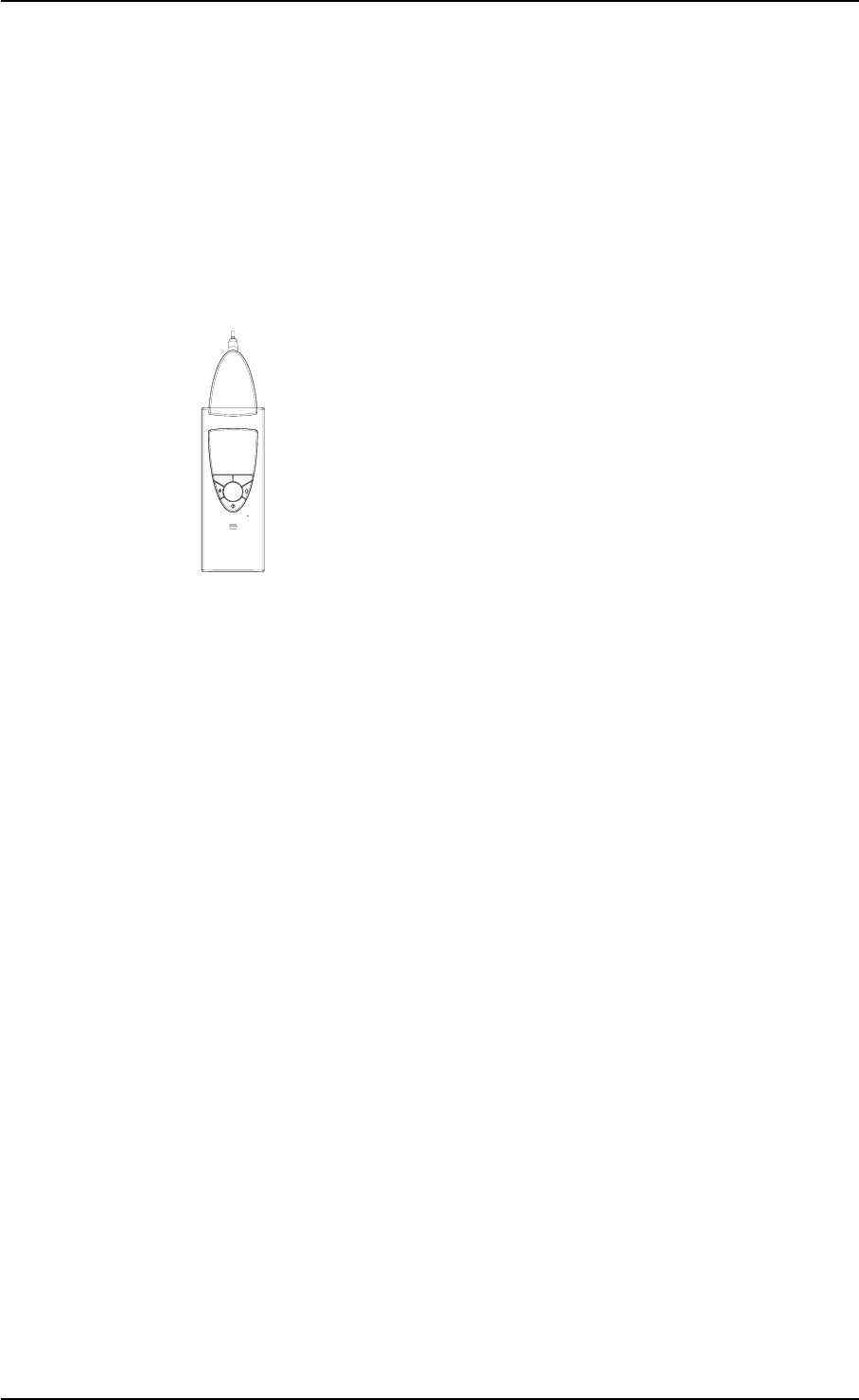
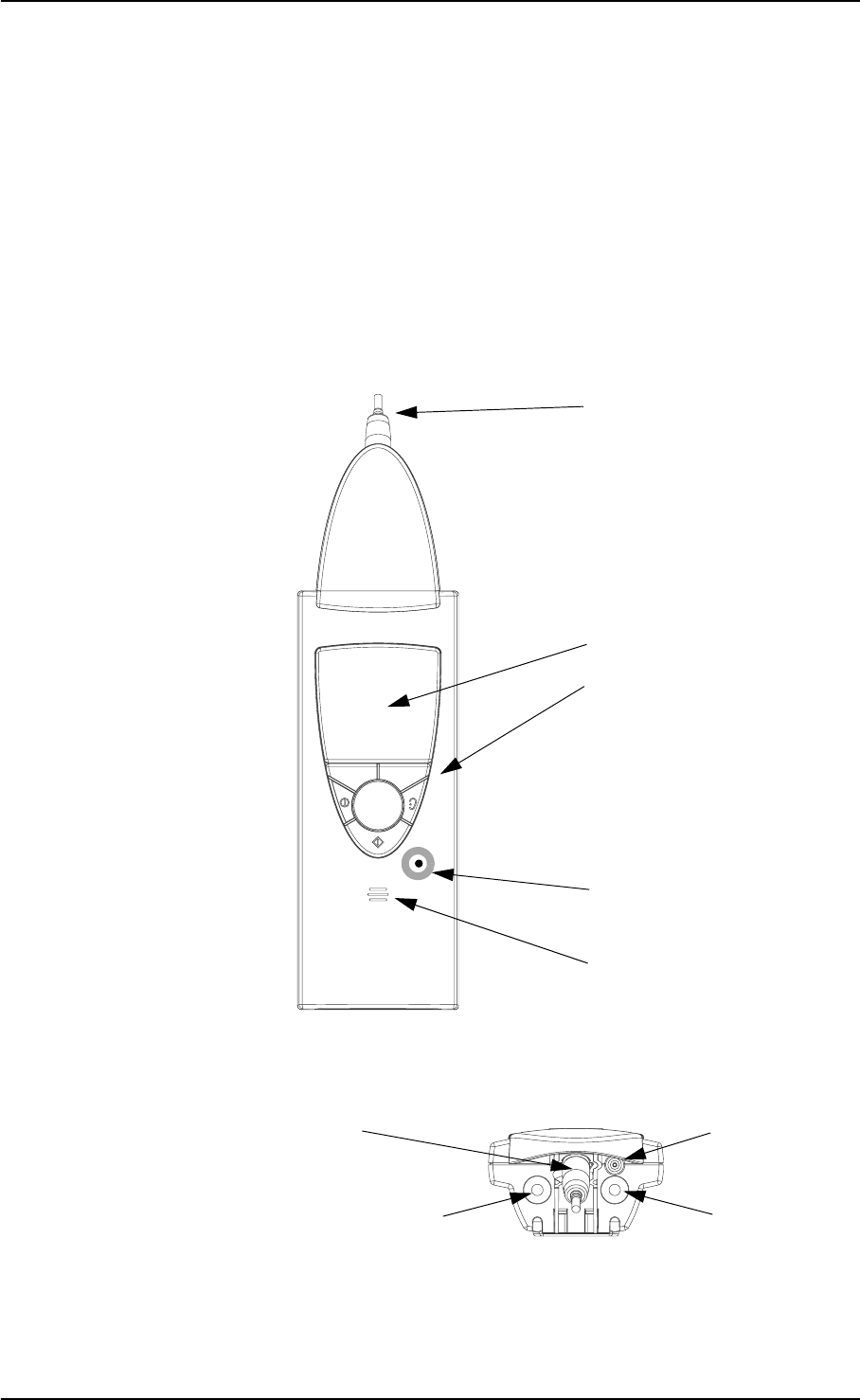
2.3.1 Front view
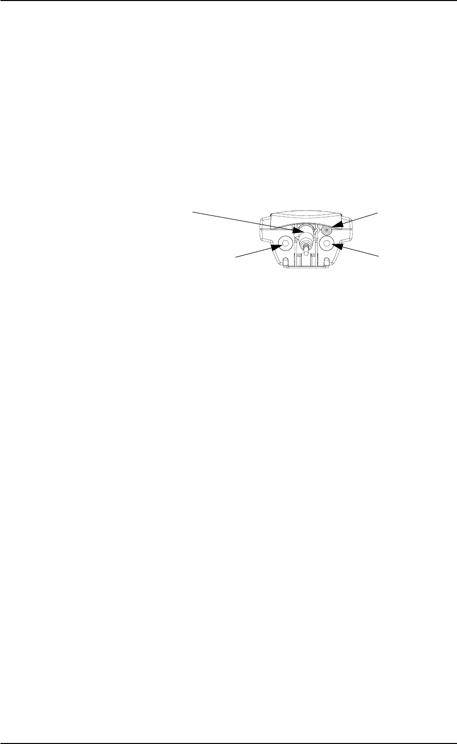
2.3.2 Top view
- Ear selector
- On/Off button
- OK button
- Scroll wheel
- Softkeys
LDC Display
Loudspeaker
Keypad with:
Probe
Device colour code
Probe socket
Probe
Contra-lateral socket
Pneumatic
connection
GN Otometrics A/S 13
OTOflex 100 User Manual
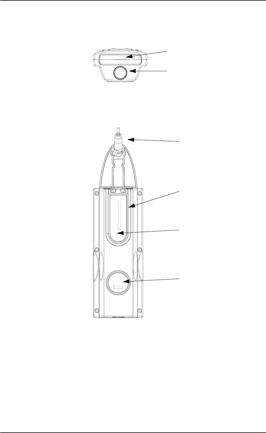
2.3.3 Bottom view
2.3.4 Reverse side view
Charger cavity
Battery casing with cover
Probe
Label
Track for probe cable
mounted with short cable
Label
14 GN Otometrics A/S
User Manual OTOflex 100
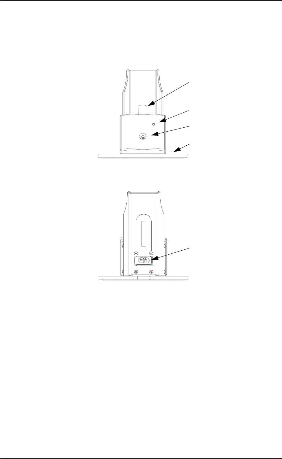
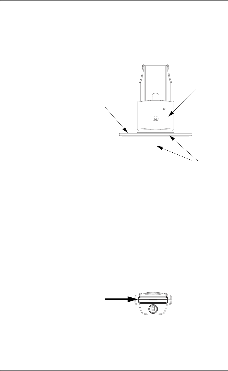
2.3.5 The charger
Front view
Rear view
Charger tab
Probe test cavity
Charging diode
for the device
Base
Mains socket
GN Otometrics A/S 15
OTOflex 100 User Manual
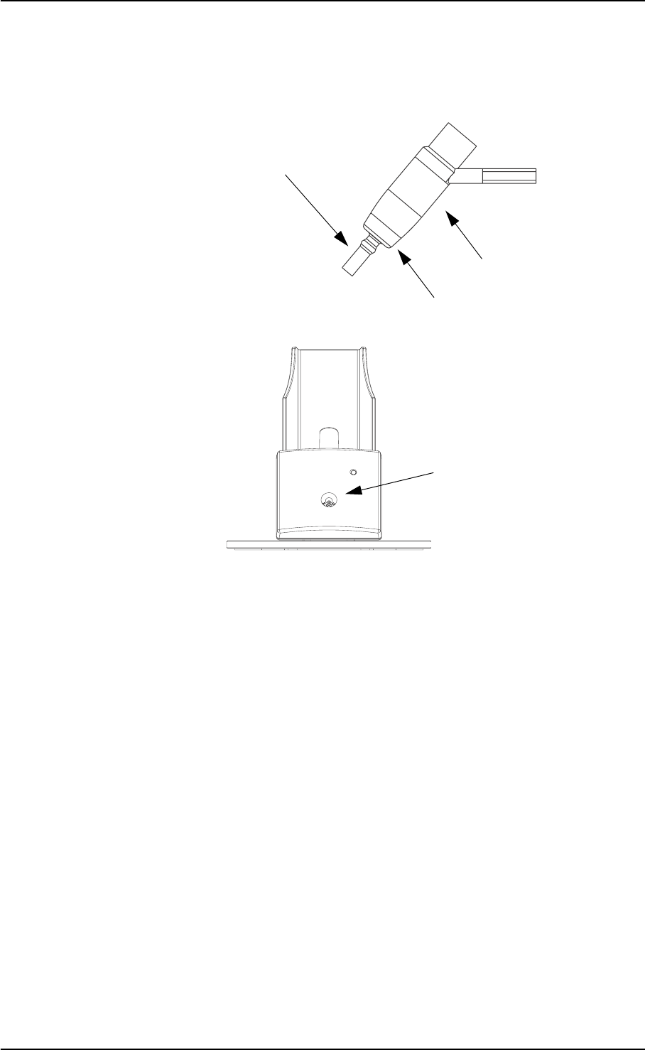
2.4 Probe
2.5 Assembly and installation
2.5.1 Location
To ensure safe performance, the OTOflex 100 must be correctly in-
stalled, and the requirements listed in Chapter 10, “Safety” on page
67 and Chapter 11, “Technical Specifications” on page 73 must be
complied with.
The OTOflex 100 can be used as a handheld device with no specific
requirements to location. However, keep the OTOflex 100 away from
all liquids and sources of heat (for detailed specifications, see Section
11.4, ‘Operating environment” on page 76.
Testing is facilitated by a moderately quiet room. A sound cabin or
sound treated room is not necessary.
Probe body
Probe tip
Threaded ring
Probe test cavity
16 GN Otometrics A/S
User Manual OTOflex 100
Assembly
Before you power the charger, mount the charger on the charger
base as shown:
2.5.2 Powering the OTOflex 100
The OTOflex 100 is powered by batteries and the charger for the
OTOflex 100 is mains powered. See the following descriptions for
powering.
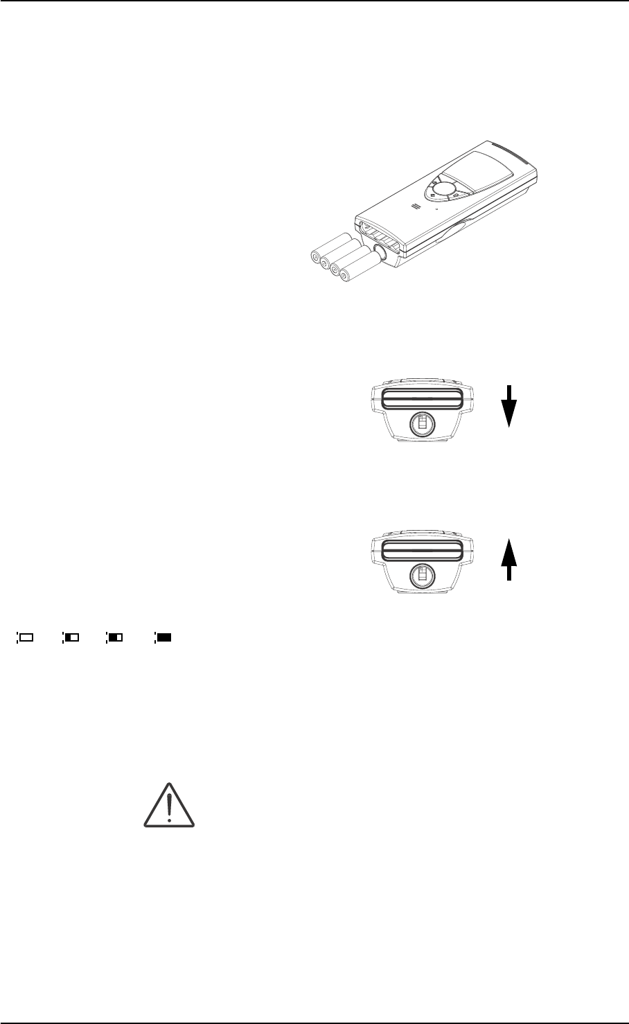
Batteries
The OTOflex 100 is delivered with batteries. Before you can operate
the OTOflex 100, you must insert the batteries:
Use only the batteries listed in Chapter 11, “Technical Specifica-
tions” on page 73.
1. The first time you insert the batteries, take out the battery
cover from the bottom of the OTOflex 100: To do so, hold the
device in one hand and pull on the slip attached to the battery
cover. This will free the cover from the battery holder. When
the cover is free, remove the slip.
Charger body
Charger base
Screws
Charger base and charger with screws etc.
GN Otometrics A/S 17
OTOflex 100 User Manual
2. Insert the batteries as shown.
3. To put the battery cover back in place, insert the cover with the
curved edge facing upwards in the opening. Press the cover
inwards and downwards until it clicks into place.
4. The next time you change batteries, press the cover inwards
and upwards until it is released and snaps out of place.
Battery status
When the OTOflex 100 is powered on, it shows the current status of
the battery in the top right corner of the display.
2.5.3 The charger
Powering
Caution:
Operating at the wrong voltage may blow the fuses! See the label on
the charger for input voltage.
Caution:
Before you connect the power cable to the charger, make sure that
the voltage from the electrical mains outlet matches the voltage
shown on the identification label on the charger.
+
++
+
100% 60% 30% 0%
18 GN Otometrics A/S
User Manual OTOflex 100
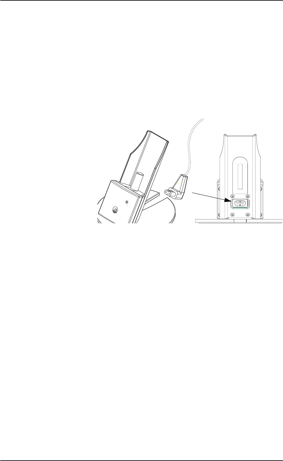
1. Connect the power cable of the OTOflex 100 charger to a
power outlet.
2. Plug the end (A) of the supplied power cable into the power
inlet on the charger (see below) and plug the other end into
the power outlet.
3. The OTOflex 100 can be used immediately when you place it in
the charger.
4. When the OTOflex 100 is placed in the charger, you can follow
the status of the charging process on the charging diode on the
charger front.
When charging, the diode indicates the following:
• Green, steady: The OTOflex 100 is fully charged.
• Yellow, steady: The OTOflex 100 is charging.
• Green, flashing: There is a fault in the charger. Contact
your supplier.
5. Leave the device to charge overnight.
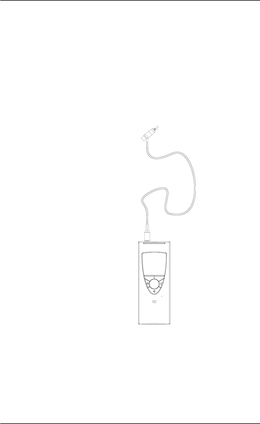
2.5.4 Connecting the OTOflex 100 probe and insert phone
The following applies both to the OTOflex 100 Ipsi probe and the
E-A-R TONE 3A insert phone.
Connecting the probe to the OTOflex 100
The OTOflex 100 comes with a probe for immittance testing. The
probe may be fitted with either a long or a short cable, depending on
how you wish to use the device.
A
GN Otometrics A/S 19
OTOflex 100 User Manual
1. Plug the probe and/or insert phone plugs into the sockets on
top of the OTOflex 100 (see the illustration below). Do not use
force when you insert the plug.
The Ipsi probe The plug of the Ipsi probe goes into the probe socket. Make
sure that you insert the pin for the pneumatic pump into the
pneumatic connection.
The E-A-R TONE 3A insert phone The plug of the E-A-R TONE 3A insert phone goes into the
contra-lateral socket.
Caution:
When you disconnect the probe, do not pull the plug by the cable.
Grip the sleeve of the plug and free it by pulling it backwards.
The probe will not be released if you pull anywhere else than on the
sleeve of the plug.
Using the probe with the probe fixture
The probe fixture is a practical place to keep the probe whenever the
device is not in use, regardless of cable length, for instance when
charging the batteries.
For instance for screening purposes you can place the probe itself in
the probe fixture.
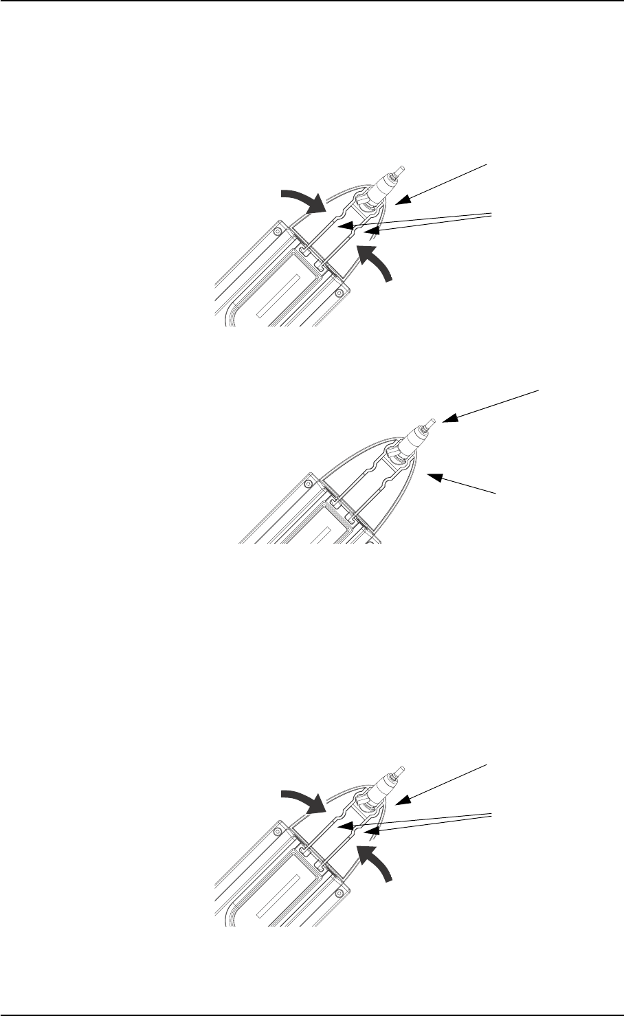
1. Plug the probe with the short cable in the probe socket.
2. Mount the probe fixture on the OTOflex 100. To do so, place
the fixture in the groove on top of the OTOflex 100.
Probe socket
Probe
Contra-lateral socket
Pneumatic
connection
20 GN Otometrics A/S
User Manual OTOflex 100
3. Snap the wings into place by pressing them downwards.
4. Place the probe in the probe fixture.
Using the probe without the probe fixture
For instance for clinical and diagnostic purposes you can use the
probe without the probe fixture.
5. If required, remove the probe from the probe fixture.
6. Remove the probe fixture from the OTOflex 100. To do so,
press the wings of the probe fixture gently towards each other,
and ease the fixture out of its groove.
Wings
Probe fixture
Probe fixture
Probe
Wings
Probe fixture
GN Otometrics A/S 21
OTOflex 100 User Manual
2.6 Display & keypad
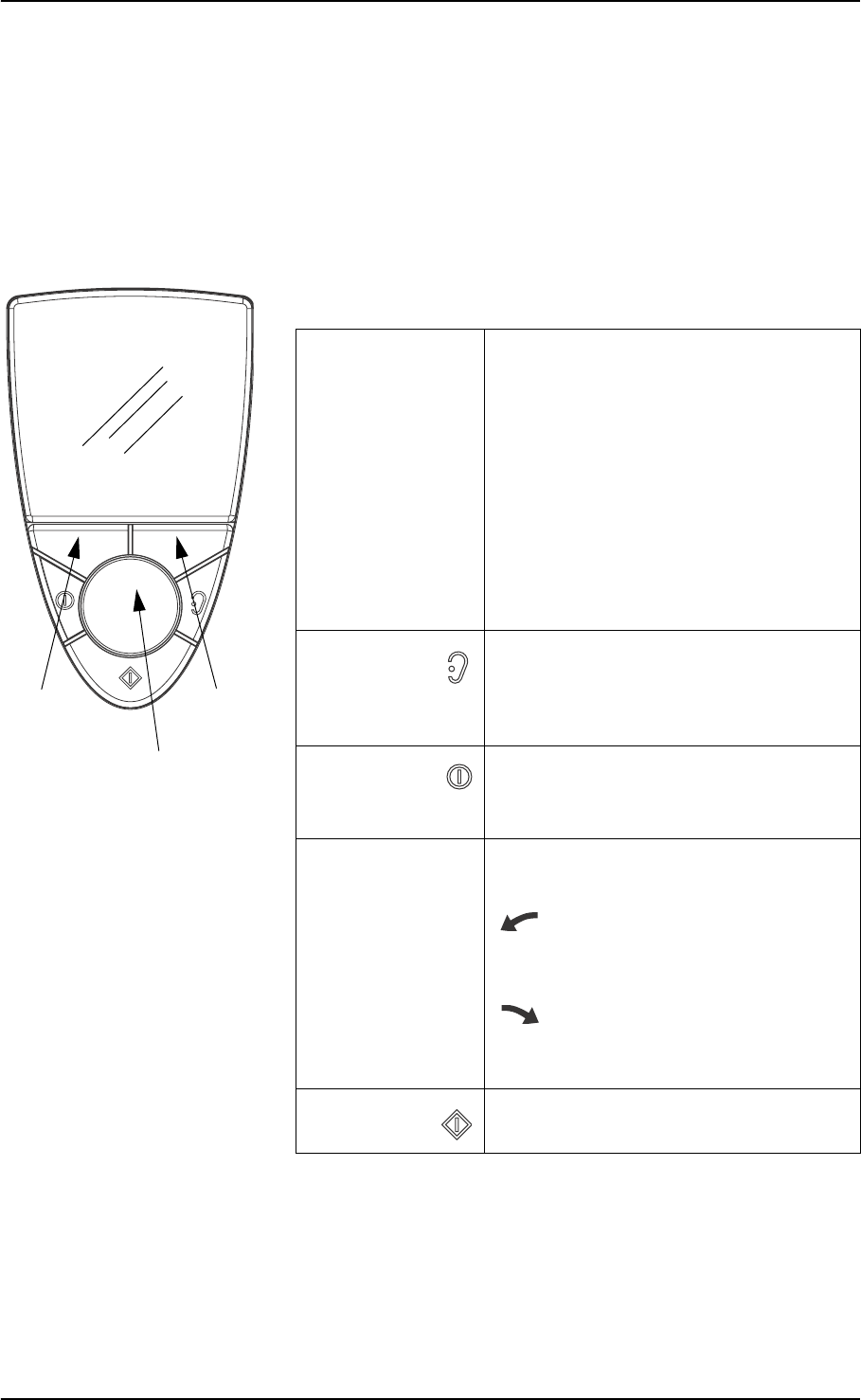
2.6.1 Keys, terms, functions
To operate the OTOflex 100, hold it with one hand (left or right). Use
your thumb to press the buttons on the keypad and turn the scroll
wheel.
2.6.2 Entering and editing data and settings
Entering data
Scroll to select the appropriate letter or digit and press Select.
Scroll wheel
Left Right
softkey
softkey
Soft keys The current functions of the two
softkeys are displayed at the bottom of
the display. Other functions than those
listed below may appear.
Left softkey Main functions:
•Cancel
• Back or up in menu hierarchy
Right softkey Main functions:
• Start/stop, Continue or Next in a
sequence
Select ear/
Pressure
release
• Toggles the ear selection associated
with the current measurement
• Pressure release button for immediate
release of air pressure
On/Off • Press briefly to turn on the device
• Press for approx. 3 seconds to turn off
the device
Scroll wheel Turn the scroll wheel to shift the focus
bar on the display:
Scroll up Counterclockwise to scroll up
• Moves the focus up or decreases a
selected value
Scroll down Clockwise to scroll down
• Moves the focus down or increases a
selected value
Select • Activates the selected item

22 GN Otometrics A/S
User Manual OTOflex 100
Editing data
To edit data such as measurement settings see Section 5.1.1, ‘Chang-
ing measurement settings” on page 43.
2.7 Device setup
When you have installed the OTOflex 100, there are a number of de-
vice settings you can customise to accomodate your use of the de-
vice.
To do so see Section 5.2, ‘Device settings” on page 50.

OTOflex 100 User Manual
GN Otometrics A/S 23
3 Preparing for testing
3.1 Preparing the test environment
3.1.1 The physical environment
• Testing is facilitated by a moderately quiet room. A sound
cabin or sound treated room is not necessary.
• Make sure that you do not test for instance under an air condi-
tioner or in front of a fan or ventilator.
• Check that there is no running water, people talking etc.
3.1.2 Hygienic precautions
• Be sure to follow any established infection control procedures
for the setting in which you are working.
• Always use clean eartips.
• Wipe the plastic probe tip with a disinfectant between patients
or replace it with a spare one.
3.2 Preparing the probe
When you select the probe for testing, you must decide how you
wish to perform the test.
The setups described below are intended to serve as inspiration, or
you can use a setup of your own choice.
For instructions on how to plug in the probe cable in the OTOflex
100, see Section 2.5.4, ‘Connecting the OTOflex 100 probe and insert
phone” on page 18.
3.2.1 Preparing for screening
The probe with the short cable is best suited for screening purposes.
It can be used in the following ways:
24 GN Otometrics A/S
User Manual OTOflex 100
Probe fitted on the OTOflex 100 cap
You can fit the probe directly on the cap of the OTOflex 100, where the
cable is folded into the cable track on the back of the OTOflex 100.
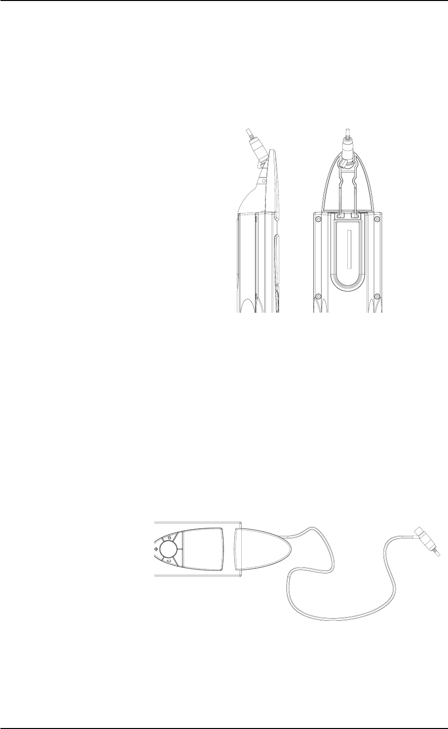
Probe and OTOflex 100 with handgrip
You can use the probe with the handgrip fitted on the OTOflex 100.
The handgrip provides enhanced maneouverability when you are
testing with a screening eartip.
If you are testing with a short probe cable and with the handle at-
tached to the device, the whole unit becomes a practical immittance
screening device.
Screening is easily done with the OTOflex 100 situated in the charger
or placed on a nearby surface, and where the handle is used with a
long probe cable
GN Otometrics A/S 25
OTOflex 100 User Manual
3.2.2 Preparing for diagnostic and clinical testing
The probe with the long cable is best suited for diagnostic and clini-
cal test purposes.
The probe is connected directly to the OTOflex 100 via the cable. This
allows for placing the OTOflex 100 near the patient, or for using it
wall-mounted in a fixed position.
If the probe fixture is mounted on the OTOflex 100, remove it (see
‘‘Using the probe without the probe fixture” on page 20.
26 GN Otometrics A/S
User Manual OTOflex 100
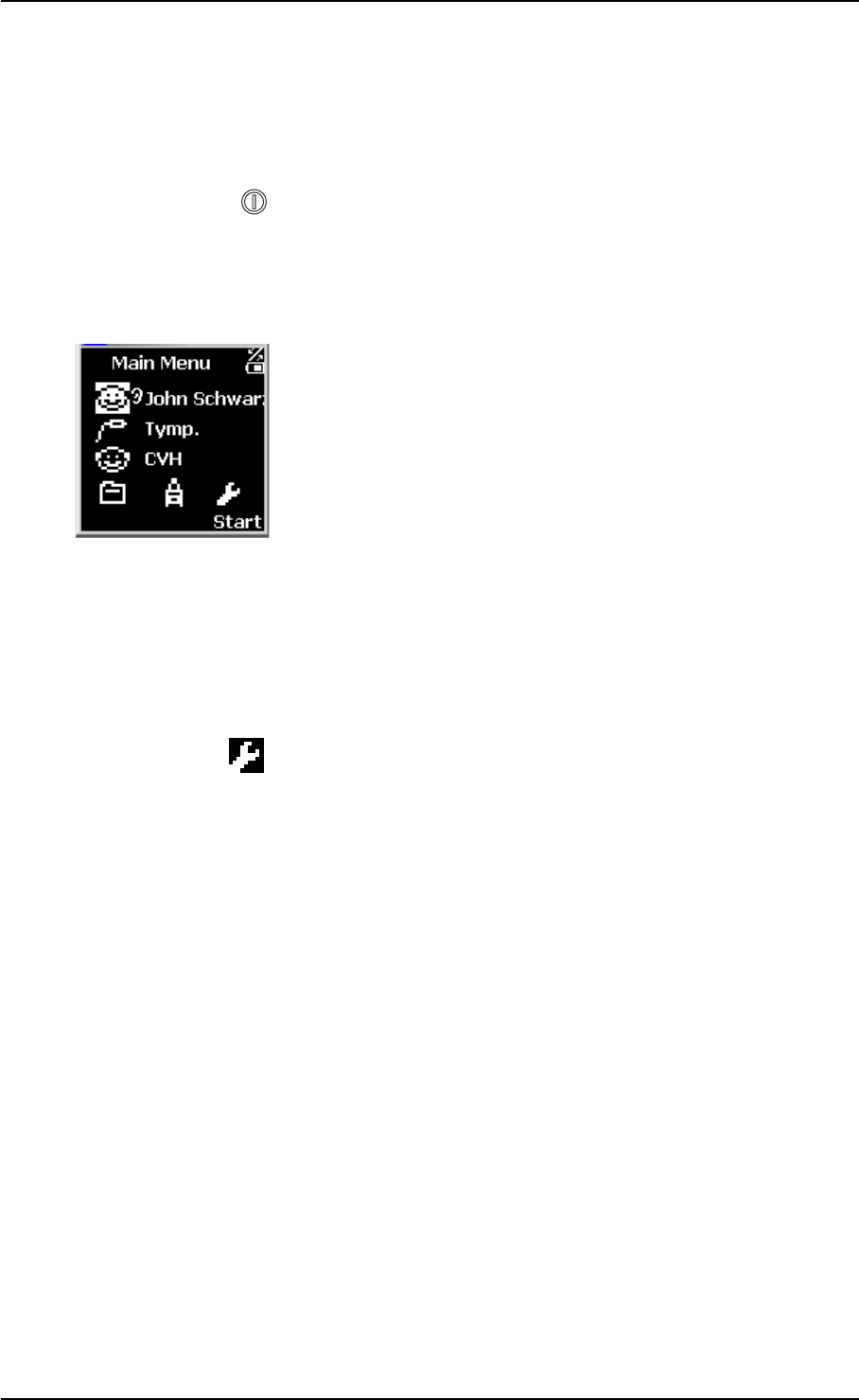
3.3 Preparing the OTOflex 100
1. Press the On/Off key on the keypad to switch on the OTOflex
100.
2. Wen you switch on the OTOflex 100, the test screen you have
selected in “Default test” in Section 5.3, ‘Sequence setup” on
page 51 will appear.
The Main Menu appears automatically. From the Main Menu
you can access all functions available in the OTOflex 100.
3. If this is the first test of the day, carry out a probe test to make
sure that the probe functions correctly (see Section 3.3.1,
‘Probe test” on page 26). If not, proceed with the section
‘‘Selecting a patient” on page 28.
3.3.1 Probe test
1. Press Select to access the Menu list, scroll to Probe test
and press Select.
2. Make sure that the probe has been cleaned and disinfected
before you place it in the probe test cavity. See Section 8.3.2,
‘Probe cleaning and maintenance” on page 58 for instructions
on when to clean and/or replace the probe tip.
This is both to make sure that the probe tip and filter do not
influence the probe test, as well as keeping the test cavity free
from contamination.
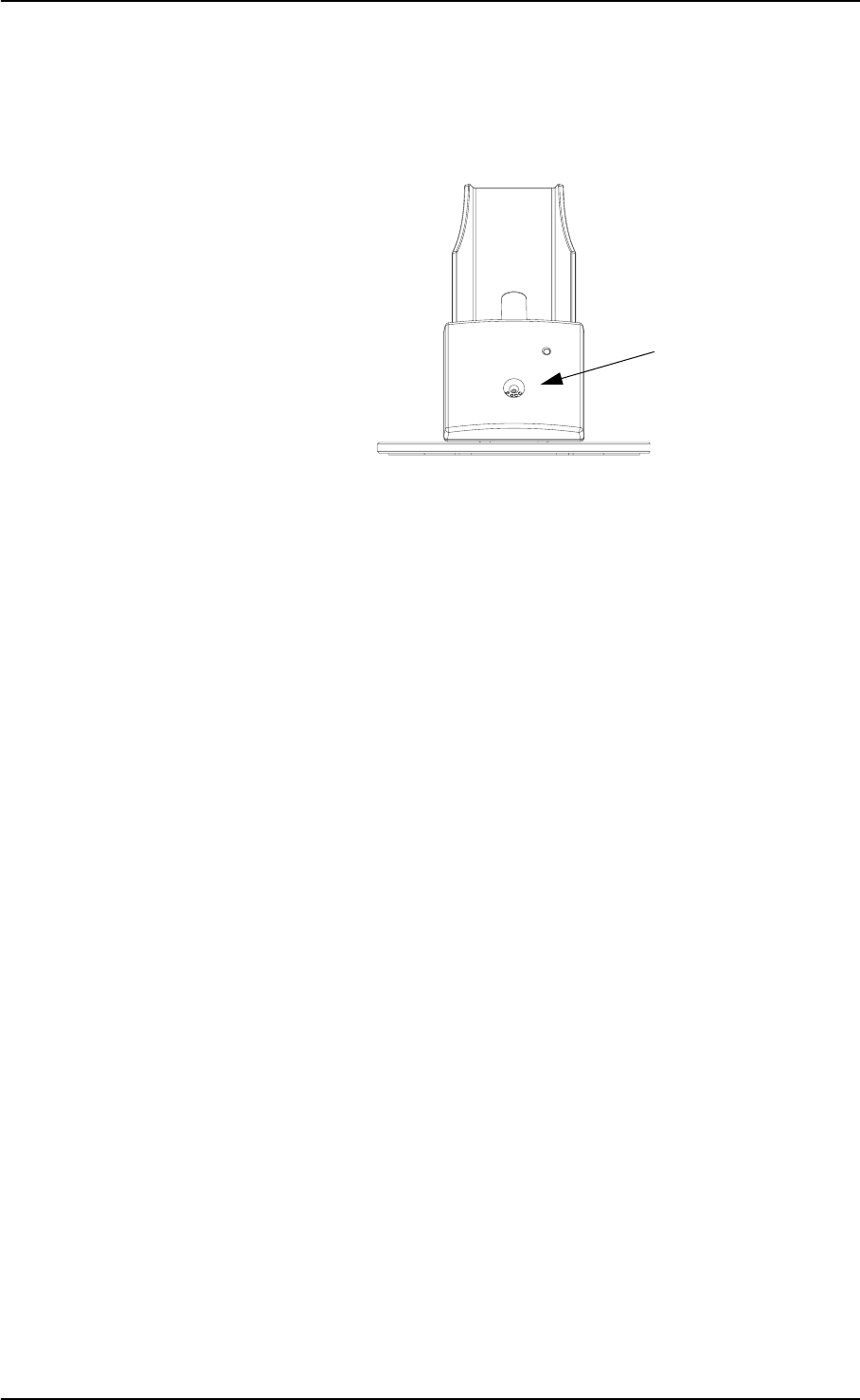
GN Otometrics A/S 27
OTOflex 100 User Manual
3. Insert the probe tip in the test cavity on the charger.
4. Press Start to start the test.
5. The probe is then tested, and a message will appear to state
whether the probe is OK.
Note:
In case of a probe error, make sure that the sound channels in the
probe tip are clear (see Section 8.3.2, ‘Probe cleaning and mainte-
nance” on page 58) and that the probe is connected. See also Section
3.3.1, ‘Probe test” on page 26.
6. If the probe should be faulty, contact your service department
for repair, and, if possible, use another probe.
3.3.2 Fitting the eartip on the probe
WARNING:
Choking hazard! Do not leave eartips unsupervised within the reach
of children.
See Section 8.3.2, ‘Probe cleaning and maintenance” on page 58 for
instructions on when to clean and/or replace the probe tip. See also
Section 8.3.7, ‘Eartips” on page 63.
1. Check the sound channels in the probe tip every time you
have used the probe. Even small amounts of cerumen or ver-
nix can block the sound channels. Clean the sound channels if
required.
Probe test cavity
28 GN Otometrics A/S
User Manual OTOflex 100
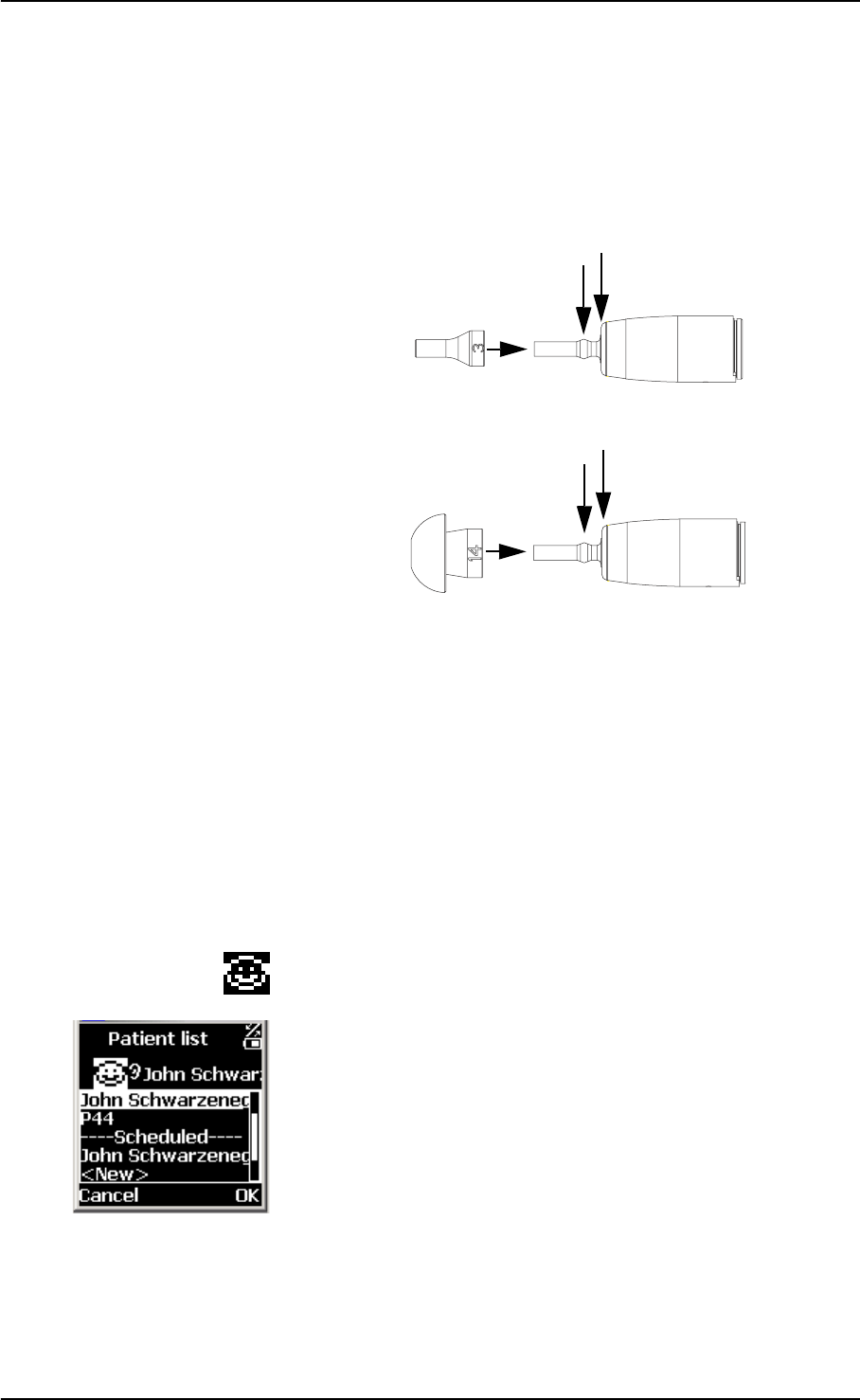
2. Select an ear tip that fits the patient’s ear canal. You may have
to try out a number of sizes in order to select the appropriate
size.
3. Gently push the eartip (A) onto the probe tip. Give it a slight
twist until it rests firmly against the base (B) of the probe.
Make sure that the eartip covers the collar (C) of the probe tip.
It is much easier to fit and remove the eartip if you turn it gen-
tly. When you do so, make sure that you hold the probe by the
probe body and not by the cable.
Note:
Accurate testing is only guaranteed if you use the eartips designed
specifically for the OTOflex 100 by GN Otometrics A/S.
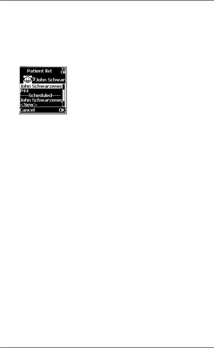
3.3.3 Selecting a patient
• On the Main Menu select the Patient icon. A list of patients
appears.
With the OtoDiagnostics Suite
If you are using the OTOflex 100 with the OtoDiagnostics Suite,
the list of patients is downloaded from the OtoDiagnostics Suite.
Scroll to the required patient and press Select.
If the patient does not appear on the list, you can enter the patient
manually or identify the patient with a voice note (see ‘‘Adding a
new patient” on page 29).
Stand-alone
If you are using the OTOflex 100 as a stand-alone device, the list
B
A
CB
A
C
GN Otometrics A/S 29
OTOflex 100 User Manual
shows only the patients you have entered in the Patient Data
screen (see ‘‘Adding a new patient” on page 29).
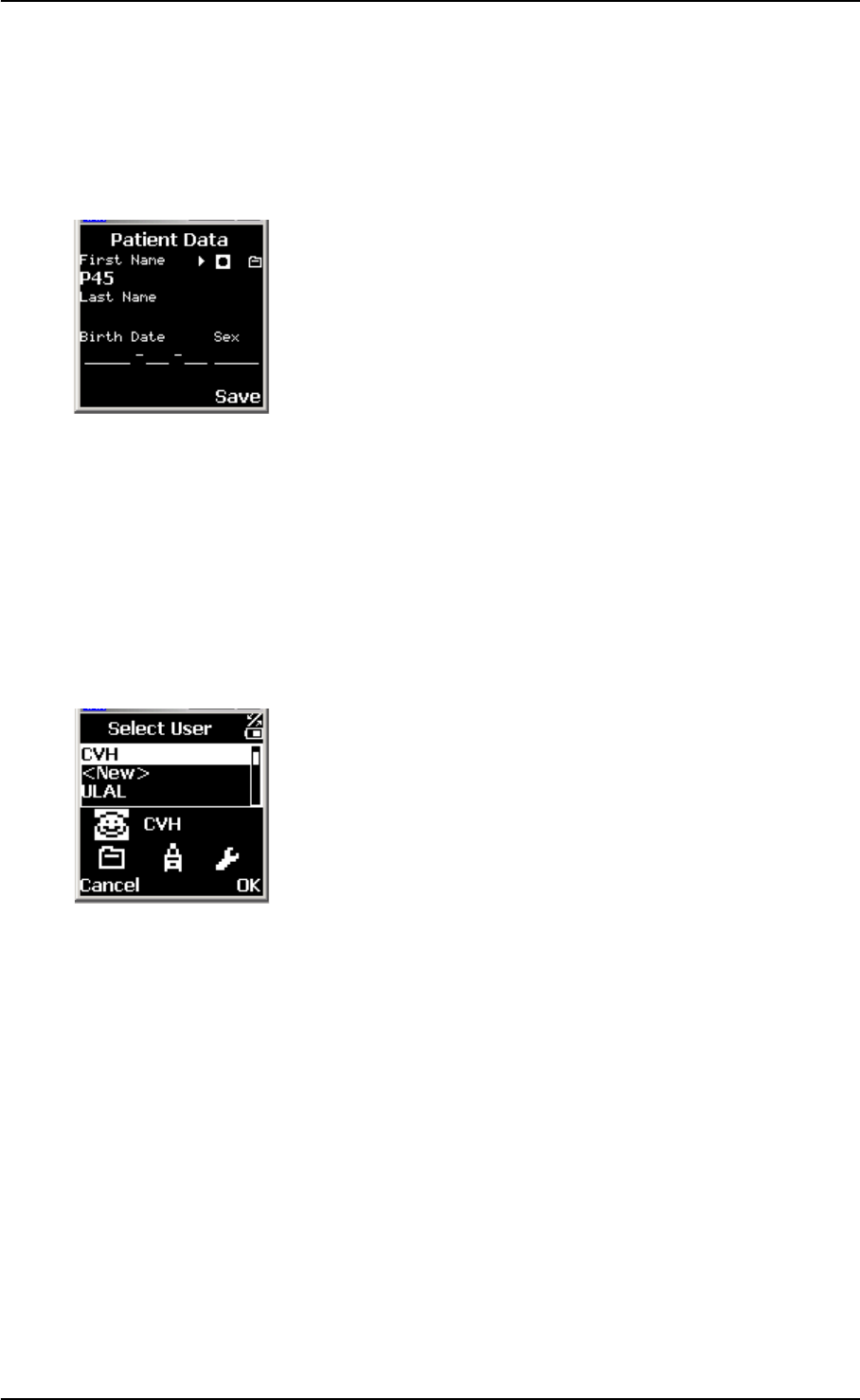
Adding a new patient
• If you wish to manually add a new patient in the Patient List
of the OTOflex 100, scroll to New in the Patient List screen
and press Select. The Patient Data screen appears.
• The patient is automatically identified by an ID number which
is listed under First Name. You can change this value.
• If required, enter the appropriate data.
• If required, press Clear to cancel incorrect input.
• When you have entered the appropriate data, press Save.
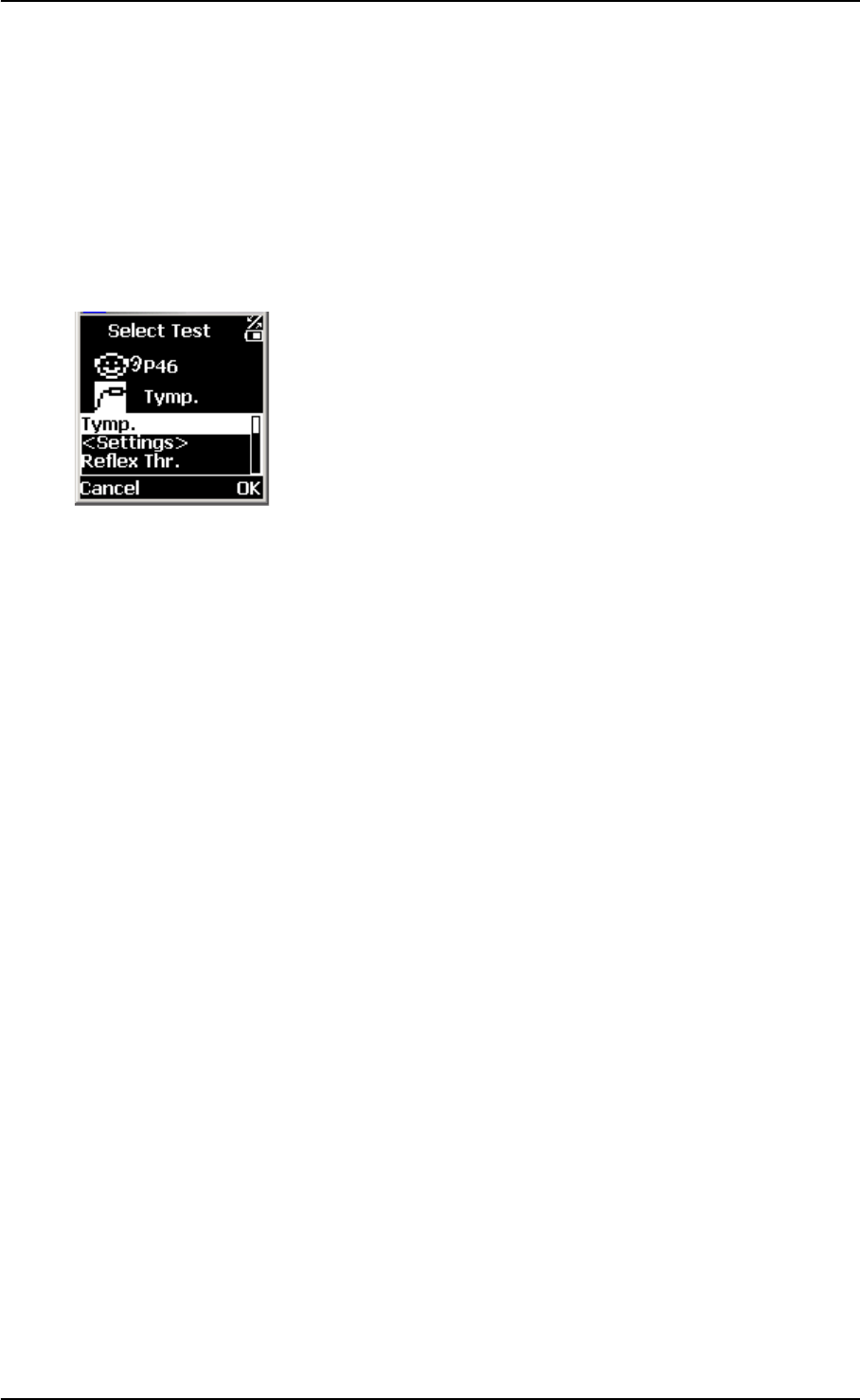
3.3.4 Selecting the user
If several users are using the OTOflex 100, you can select the appro-
priate user for the session.
• Scroll to the User icon on the main screen and press Select. A
list of users appears.
• Scroll to the appropriate user and press Select.
With the OtoDiagnostics Suite
If you are using the OTOflex 100 with the OtoDiagnostics
Suite, the list may show a whole range of users. Scroll to
select and press OK.
If the user does not appear on the list, you can enter the user
manually (see ‘‘Adding a new user” on page 29).
Stand-alone
If you are using the OTOflex 100 as a stand-alone device, the
list shows only the users you have entered (see ‘‘Adding a
new user” on page 29).
Adding a new user
• If you wish to manually add a new user in the user list of the
OTOflex 100, select New in the Select User screen and press
OK.
• Enter the appropriate data.
• When you have entered the appropriate data, press Save.
Press Clear to cancel incorrect input.
30 GN Otometrics A/S
User Manual OTOflex 100
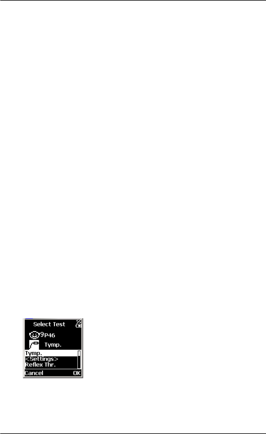
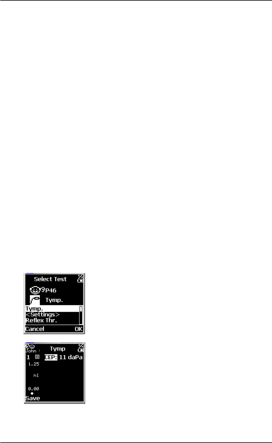
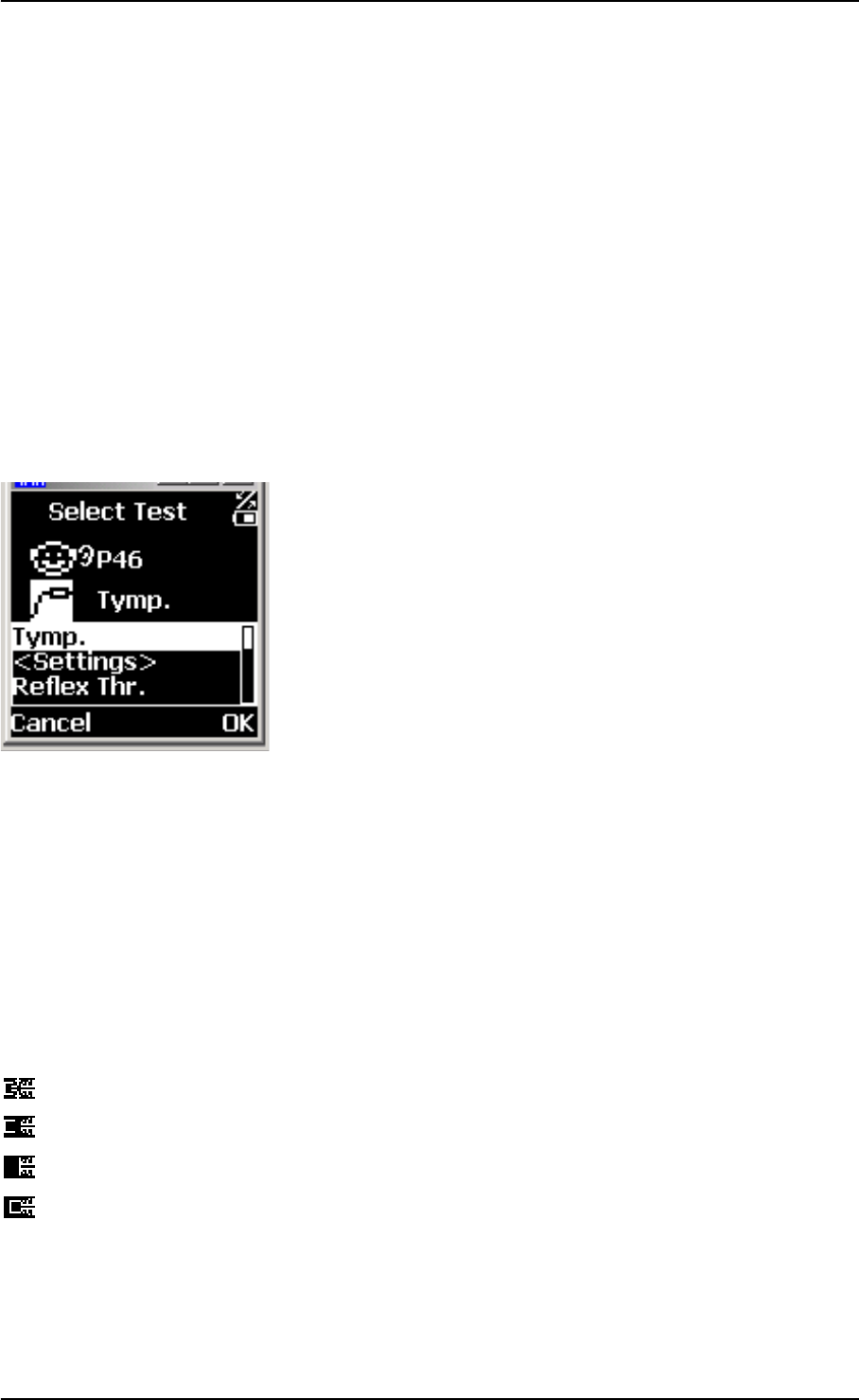
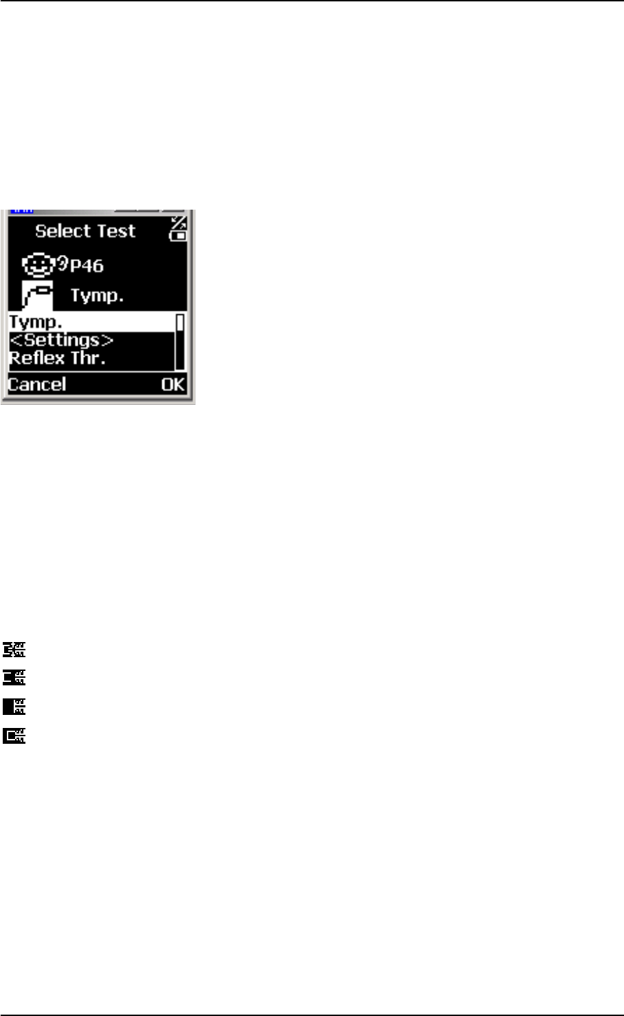
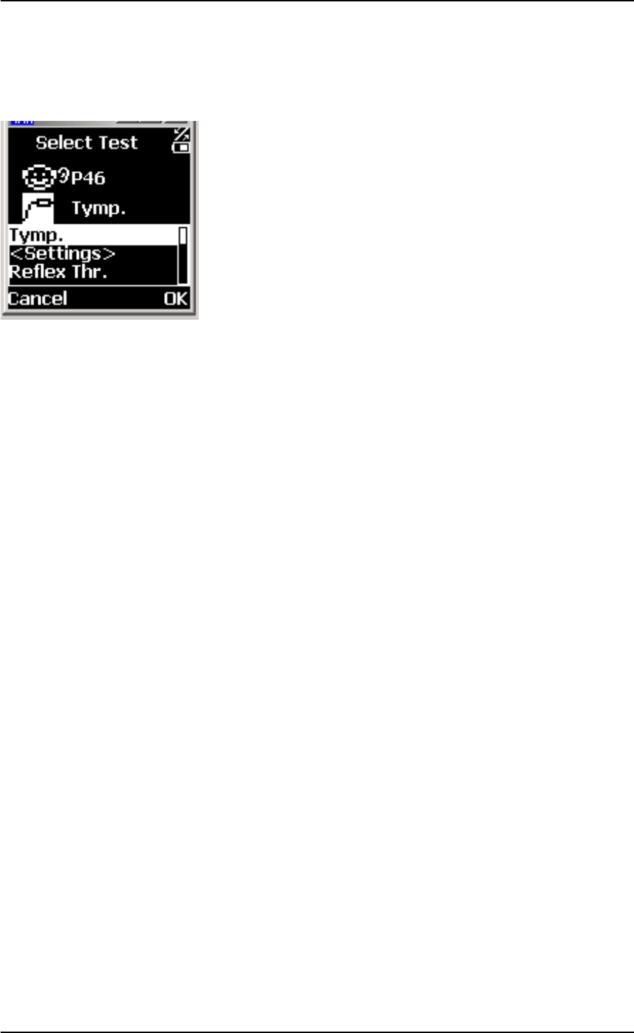
3.3.5 Selecting the test type
Note:
The tests available depend on the configuration of your OTOflex 100.
1. Scroll to select the Test icon on the Main Menu and press
OK.
2. Scroll to the appropriate test type and press Select.
3.4 Preparing the patient
1. Position the patient so that you can easily access the ear to be
tested.
2. Grasp the pinna and gently pull back and slightly away from
the patient's head.
3. Look into the ear canal. If possible, do an otoscopy to assess
the status of the outer ear before you insert the probe.
If you can see apparent narrowing of the ear canal, it may be
blocked by vernix or debris, or it may not be straight.
Note:
Because infants’ ear canals are very soft, they are easily
pressed out of shape.
• If this is the case, wait until the ear canal returns to its orig-
inal shape. Release the pinna and try again. Gently mas-
saging the area may help opening the ear canal.
4. If the ear canal is blocked, this may effect the result of the test.
Clean the ear canal if required.
5. If the patient has a cold, it may affect testing. Ask the patient
to clear his throat and, if required, blow his nose before you
start testing. Then ask the patient to equalise the pressure, for
instance by yawning or swallowing.
GN Otometrics A/S 31
OTOflex 100 User Manual
3.4.1 Selecting the ear and fitting the probe with eartip in the ear canal
Selecting ear to be tested
Regardless of the type of test you have selected, you must select the
ear on which you wish to start the test.
1. If you have not already done so, select the Patient icon on
the OTOflex 100. A list of patients appears. Select the appropri-
ate patient.
2. Toggle the Ear selection key on the keypad until the Ear
icon on the display shows the correct ear.
Fitting the eartip
WARNING:
Be careful not to insert the probe too far into the ear canal of prema-
ture babies and newborns.
Caution:
Never insert the probe without a proper size ear tip applied.
Using a probe with an unsuitably sized eartip or applying excessive
force may irritate the ear canal.
1. To fit the probe with the eartip in the ear canal of the patient,
gently pull the pinna back and slightly down and insert the
probe, twisting it slightly as you insert it.
2. Make sure that the eartip fits well. Any leakage may increase
the test duration because of distortion and excessive noise.
You can easily compensate for spontaneous movements of the
patient’s head by reducing the pull on the probe cable. To do
so, form a big loop, which you hold loosely with one hand
close to the head of the patient.
Note:
The eartip can be used for both ears. However, if you suspect infec-
tion in one ear, exchange the eartip and clean the probe tip before
you continue testing on the other ear.
See Chapter 4, “Tests” on page 33 on how to proceed with the spe-
cific tests.

32 GN Otometrics A/S
User Manual OTOflex 100
OTOflex 100 User Manual
GN Otometrics A/S 33
4Tests
With the OTOflex 100 you can perform a range of middle ear tests,
which are divided into the following major categories:
Tympanometry
•See Section 4.2.1, ‘Tympanometric sweep” on page 34.
Reflex Testing
•See Section 4.3.1, ‘Acoustic Reflex Threshold” on page 37.
•See Section 4.3.2, ‘Acoustic Reflex Decay” on page 38.
•See Section 4.3.3, ‘Eustachian Tube Function - Perforated (ETF-
P)” on page 41.
These tests you can do either individually or as part of a sequence,
where you can set up the sequence to suit your purposes.
4.1 Starting up the test
1. Do as described in Chapter 3, “Preparing for testing” on page
23.
2. Tell the patient that there will be a change of pressure in the
ear and that there will be a probe tone.
3. If you have not already done so, select the appropriate test
type: press Select, scroll to the required test type on the
Menu list and press Select.
4. The test screen is shown.
Default settings
The test is defined by a range of settings and functions. These set-
tings you can change to define the overall setup of this test. They are
stored in the measurement settings setup and apply whenever you
select this test type.
5. If you want to change the basic default settings, see
34 GN Otometrics A/S
User Manual OTOflex 100
Section 5.1.3, ‘Tympanometric settings” on page 44,
Section 5.1.4, ‘Reflex Threshold settings” on page 46,
Section 5.1.5, ‘Reflex Decay settings” on page 49.
6. If you do not want to change the basic default settings, go to
Section 4.2.1, ‘Tympanometric sweep” on page 34,
Section 4.3.1, ‘Acoustic Reflex Threshold” on page 37, or
Section 4.3.2, ‘Acoustic Reflex Decay” on page 38.
4.2 Tympanometry
In Tympanometry you can measure the variation of the compliance
(or immittance) of the eardrum and the ossicular chain by applying
controlled changes in static pressure.
Tympanometry is used to indicate or confirm disorders such as os-
sicular discontinuity, otosclerosis (rigidity in the ossicular chain),
flaccid (hypermobile) eardrum due to aging, perforated eardrum,
obstruction of the ear canal, middle-ear fluid, dried ear-wax and
Eustachian Tube malfunctions.
The result of the test is shown in a tympanogram, which is a graph-
ical display of these parameters.
4.2.1 Tympanometric sweep
If you have not already done so, do as described in Chapter 3, “Pre-
paring for testing” on page 23 and Section 4.1, ‘Starting up the test”
on page 33.
1. If required, press Select, scroll to A: Tympanometry and
press Select.
2. The Tympanometry screen appears.
3. If required, press the Select Ear key or toggle the Ear icon
to select the ear on which you wish to start the test.
Quick access settings
Quick access is provided to a range of settings and functions. These
settings you can change to suit your purposes. They apply only to
GN Otometrics A/S 35
OTOflex 100 User Manual
the current test, and are not stored in the measurement settings set-
up.
1. To access these settings press Select, and scroll to the bottom
of the Menu list, where these settings and functions are
listed.
With this test you can change the pump pressure and volume set-
tings during the test.
2. Change the required settings and press Save and Back to
return to the Tympanometry screen.
3. Press Start to start the test.
Probe fit
If the probe does not fit correctly, an icon on the screen will
indicate that there is a leak or that the probe is blocked. Adjust
the position of the probe , check the probe tip or use another
probe tip or eartip. The test continues when the probe fit is
good.
Note:
If the patient seems to be troubled by the pressure applied to
the ear currently being tested, press the Pressure release
button. The pump pressure is relieved immediately.
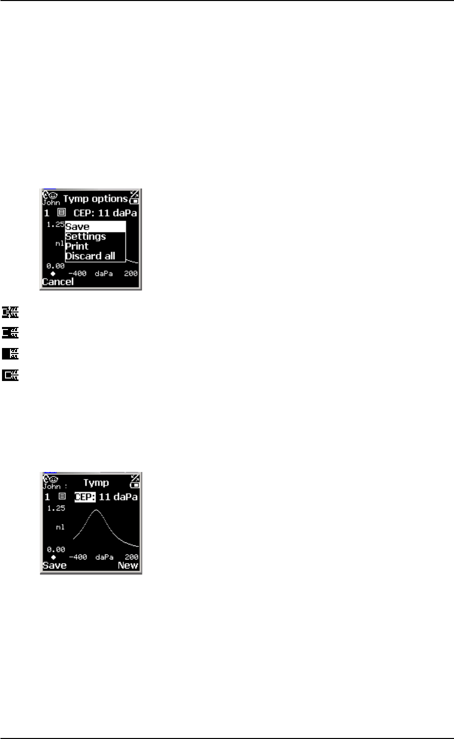
4. The test as it progresses is shown on the display.
5. When the test is completed, a tympanometric curve is dis-
played.
A sweep with a normal result will appear as the example
shown.
6. If you need to make another test, for instance if the test result
was not satisfactory, press New.
You can make 3 separate tests for each specific test type per
patient. If you make more than 3 tests, the first test will be
replaced by the new one. Changing this setting is described in
“Auto next”, Section 5.1.3, ‘Tympanometric settings” on
page 44.
Leak
Not inserted properly
Blocked
OK
36 GN Otometrics A/S
User Manual OTOflex 100
Swapping ear results
If you have selected the wrong ear, when you make the test, you can
swap ears so that the test result refers to the correct ear.
1. Press Select to access the Menu list.
2. Scroll to Swap ear data.
Saving test results
1. If you want to save the test result, press Save.
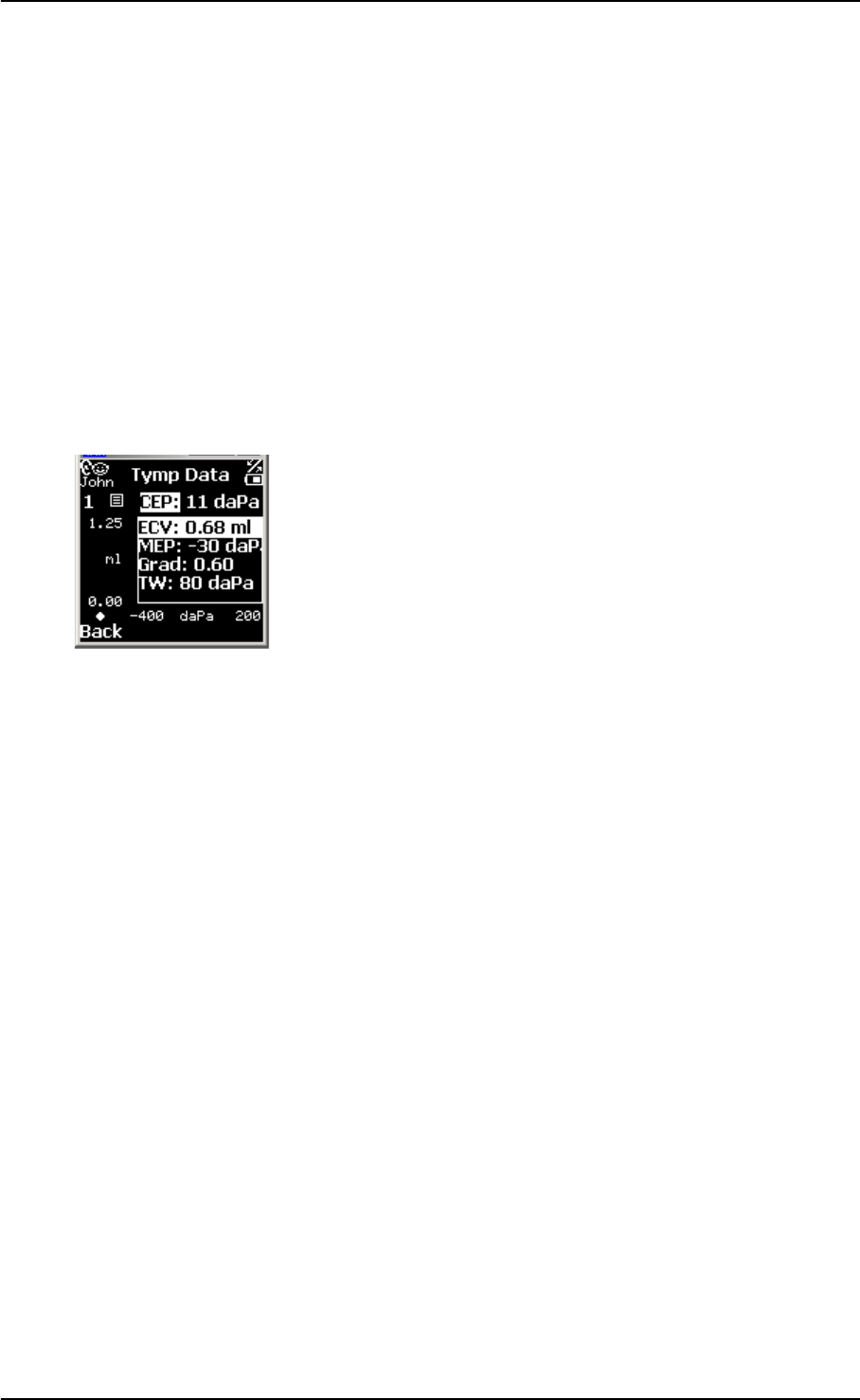
Viewing the Tymp Sweep test results
1. Press Select to access the Menu list.
A list showing the data registered during the test is shown.
2. Press Back to leave the data list.
Discarding test data
You can discard the test data, for instance if the test results were not
satisfactory.
1. Press Select to access the Menu list.
2. Scroll to Discard test.
Printing the Tymp Sweep test results
1. Press Select to access the Menu list.
2. Select Print report.
4.3 Reflex testing
In audiology, the term “Reflex testing” refers to the Stapedius Reflex,
a mechanism which automatically tensions both eardrums when a
particularly loud sound occurs, probably to prevent overload and
possible damage to the hearing mechanism. With the OTOflex 100
you can make a range of measurements of a patient’s reflexes. This
is done by applying a controlled acoustic stimulus and then measur-
ing the change in acoustic impedance which will be observed if the
ear is healthy.
The change in Compliance which results from the functioning of the
reflex mechanism is very small. It is further diminished, if the ear-
drum is tensioned by a static pressure differential between the ear
canal and the middle ear. If you are not certain whether the Middle-
GN Otometrics A/S 37
OTOflex 100 User Manual
Ear Pressure is close to atmospheric pressure, do a tympanometric
test first.
Threshold testing tests the function of the Stapedius muscle. A weak
Stapedius muscle cannot sustain tension in the eardrum during pro-
longed presentation of a sound, which is loud enough to provoke
Reflex. This test measures a reflex records the decay caused by a
weak Stapedius muscle.
4.3.1 Acoustic Reflex Threshold
If you have not already done so, do as described in Chapter 3, “Pre-
paring for testing” on page 23 and Section 4.1, ‘Starting up the test”
on page 33.
1. If required, press Select, scroll to A: RThreshold and press
Select.
2. The Reflex Threshold screen appears.
3. If required, press the Select Ear key or toggle the Ear icon
to select the ear on which you wish to start the test.
Quick access settings
Quick access is provided to a range of settings and functions. These
settings you can change to suit your purposes. They apply only to
the current test, and are not stored in the measurement settings set-
up.
1. To access these settings press Select, and scroll to the bottom
of the Menu list, where these settings and functions are
listed.
With this test you can change the pump pressure and volume set-
tings during the test. Deflection curves are generated.
2. Change the required settings and press Save and Back to
return to the Reflex Threshold screen.
3. Press Start to start the test.
Probe fit
If the probe does not fit correctly, an icon on the screen will
indicate that there is a leak. Adjust the position of the probe or
use another eartip. The test continues when the probe fit is
good.
Note:
If the patient seems to be troubled by the high stimulus levels
Leak
Not inserted properly
Blocked
OK

38 GN Otometrics A/S
User Manual OTOflex 100
applied to the ear currently being tested, press the Pressure
release button. The pump pressure is relieved immediately.
4. The test as it progresses is shown on the display.
5. When the test is completed, a deflection curve is displayed.
6. If you need to make another test, for instance if the test result
was not satisfactory, press New.
You can make 3 separate tests for each specific test type per
patient. If you make more than 3 tests, the first test will be
replaced by the new one. Changing this setting is described in
Section 5.1.4, ‘Reflex Threshold settings” on page 46.
Swapping ear results
If you have selected the wrong ear, when you make the test, you can
swap ears so that the test result refers to the correct ear.
1. Press Select to access the Menu list.
2. Scroll to Swap ear data.
Saving test results
1. If you want to save the test result, press Save.
Viewing Reflex Threshold test results
1. Press Select to access the Menu list.
A list showing the data registered during the test is shown.
2. Press Back to leave the data list.
Discarding test data
You can discard the test data, for instance if the test results were not
satisfactory.
1. Press Select to access the Menu list.
2. Scroll to Discard test.
Printing the Reflex Threshold test results
1. Press Select to access the Menu list.
2. Select Print report.
4.3.2 Acoustic Reflex Decay
A weak Stapedius muscle cannot sustain tension in the eardrum
during prolonged application of a sound loud enough to provoke
GN Otometrics A/S 39
OTOflex 100 User Manual
Reflex. This test measures a reflex , and can be used to record the de-
cay caused by a weakening Stapedius muscle.
If you have not already done so, do as described in Chapter 3, “Pre-
paring for testing” on page 23 and Section 4.1, ‘Starting up the test”
on page 33.
1. If required, press Select, scroll to A: RDecay and press
Select.
2. The Reflex Decay screen appears.
3. If required, press the Select Ear key or toggle the Ear icon
to select the ear on which you wish to start the test.
Quick access settings
Quick access is provided to a range of settings and functions. These
settings you can change to suit your purposes. They apply only to
the current test, and are not stored in the measurement settings set-
up.
1. To access these settings press Select, and scroll to the bottom
of the Menu list, where these settings and functions are
listed.
With this test you can change the pump pressure and volume set-
tings during the test. Deflection curves are generated.
2. Change the required settings and press Save and Back to
return to the Reflex Decay screen.
3. Press Start to start the test.
Probe fit
If the probe does not fit correctly, an icon on the screen will
indicate that there is a leak. Adjust the position of the probe or
use another eartip. The test continues when the probe fit is
good.
Note:
If the patient seems to be troubled by the high stimulus levels
applied to the ear currently being tested, press the Pressure
release button. The pump pressure is relieved immediately.
4. The test as it progresses is shown on the display.
5. When the test is completed, a deflection curve is displayed.
6. If you need to make another test, for instance if the test result
was not satisfactory, press New.
Leak
Not inserted properly
Blocked
OK

40 GN Otometrics A/S
User Manual OTOflex 100
You can make 3 separate tests for each specific test type per
patient. If you make more than 3 tests, the first test will be
replaced by the new one. Changing this setting is described in
Section 5.1.4, ‘Reflex Threshold settings” on page 46.
Swapping ear results
If you have selected the wrong ear, when you make the test, you can
swap ears so that the test result refers to the correct ear.
1. Press Select to access the Menu list.
2. Scroll to Swap ear data.
Saving test results
1. If you want to save the test result, press Save.
Viewing Reflex Decay test results
1. Press Select to access the Menu list.
A list showing the data registered during the test is shown.
2. Press Back to leave the data list.
Discarding test data
You can discard the test data, for instance if the test results were not
satisfactory.
1. Press Select to access the Menu list.
2. Scroll to Discard test.
Printing the Reflex Decay test results
1. Press Select to access the Menu list.
2. Select Print report.
GN Otometrics A/S 41
OTOflex 100 User Manual
4.3.3 Eustachian Tube Function - Perforated (ETF-P)
1. If required, press Select, scroll to A: ETF-P and press Select.
2. The ETF-P screen appears.
3. If required, press the Select Ear key or toggle the Ear icon
to select the ear on which you wish to start the test.
4. Change the required settings and press Save and Back to
return to the ETF-P screen.
5. Press Start to start the test.
6. The test as it progresses is shown on the display.
7. If you need to make another test, for instance if the test result
was not satisfactory, press New.
Swapping ear results
If you have selected the wrong ear, when you make the test, you can
swap ears so that the test result refers to the correct ear.
Saving test results
1. If you want to save the test result, press Save.
Viewing ETF-P test results
1. Press Select to access the Menu list.
A list showing the data registered during the test is shown.
2. Press Back to leave the data list.
Discarding test data
You can discard the test data, for instance if the test results were not
satisfactory.
1. Press Select to access the Menu list.
2. Scroll to Discard test.
Printing the ETF-P test results
1. Press Select to access the Menu list.
2. Select Print report.

42 GN Otometrics A/S
User Manual OTOflex 100

OTOflex 100 User Manual
GN Otometrics A/S 43
5 Setup
5.1 Measurement settings
When you are going to do a test, and you have selected the specific
test screen in the OTOflex 100, you can change a number of test spe-
cific settings.
These settings you can either download from the OtoDiagnostics
Suite, or you can change them directly in the OTOflex 100.
5.1.1 Changing measurement settings
To change the settings directly in the OTOflex 100, select the appro-
priate test screen and then select the Measurement Settings dialog
box:
1. Press Select, scroll to the appropriate test type and press
Select again. The test screen is displayed.
2. Press Select, scroll to Meas. settings, and press Select
again. The test specific settings menu is shown.
3. For a description of the test specific settings see:
•Section 5.1.3, ‘Tympanometric settings” on page 44
•Section 5.1.4, ‘Reflex Threshold settings” on page 46
•Section 5.1.5, ‘Reflex Decay settings” on page 49
The settings may be shown in abbreviated form. The actual
wording is included in square brackets, as for instance in
Pump dir[ection].
4. Scroll to the setting you want to change.
5. Press Select. The value is shown in a highlighted frame.
6. Scroll to the desired value and press Select to select the set-
ting. The new setting is now shown in a highlighted box.
7. To save changes you have made to the settings, press Save.

44 GN Otometrics A/S
User Manual OTOflex 100
5.1.2 Uploading measurement settings to the OtoDiagnostics Suite
1. Press Select.
2. Scroll to Upload data, and press Select again. The test spe-
cific settings menu is shown.
5.1.3 Tympanometric settings
Probe tone Default: 226 Hz
If you select 226 Hz, you can set admittance to be shown in mmho
or in ml in the field Y unit listed below.
If you select frequencies other than 226 Hz, admittance is shown only
in mmho. The value in Y unit below automatically changes to
mmho.
• 226 Hz
• 1000 Hz
Recommended for testing on infants younger than 4-6
months.
Press rng [Pressure range] Default: Norm
•Norm
+200 to -400 daPa
•Ext.
+400 to -600 daPa
Leak det[ection] Default: On
Pump dir[ection] Default: Neg(ative)
Pump speed Default: 400 daPa/s
• 50, 100, 200, 400 daPa
• AFAP (As Fast As Possible)
500 daPa/s, reduces the speed at peak to 400 daPa/s.
AFAP is particularly suited for screening with screening ear-
tips, and if you suspect difficulty in maintaining seal, for
instance in patients that are difficult to test, such as infants.
Start press[ure] Default: 200 daPa

GN Otometrics A/S 45
OTOflex 100 User Manual
Stop on data Default: On
The measurement stops automatically when data is available for
tympanometric peak pressure (TPP) and tympanometric width
(TW) and Gradient (TG).
Auto classify Default: On
This setting relates to the setting in “Normal area” below.
Auto next Default: Off
•Off
If you make a new measurement, it will overwrite the current
measurement.
•On
If you make a new measurement, it is assigned the next
number in the series of measurements. This means that after
measurement no. 1, the next measurement will be assigned no.
2, to a maximum of three (3) individual measurements. After
no. 3, no. 1 will be overwritten.
Normal area Default: Adult
•None
•Adult
Based on Modified Jerger norm range.
• Infant
Y unit Default: mmho
The1000 Hz frequency is as default shown in mmho. If required, you
can set the frequency 226 Hz to be shown in ml.
X unit Default: daPa
Y scale Default: 1.5 mmho
1 cc = 1 ml.
You can set the vertical axis of the Tymp. sweep display to:
Auto
1.5 cc
3.0 cc
4.5 cc
If you select Auto, the most suitable scale will be selected automat-
ically to give the best display of the current tympanogram.
Note:
Auto can result in different scales being selected for the left and
right tympanograms. Check the values shown in the Y-axis.

46 GN Otometrics A/S
User Manual OTOflex 100
Smooth crv [curve] Default: Off
Base line Default: On
•On
•Off
If you select a probe tone frequency other than 226 Hz, the
base line setting is automatically set to “Off”.
5.1.4 Reflex Threshold settings
Man[ual] timing Default: Off
Probe tone Default: 226 Hz.
If you select 226 Hz, you can set admittance to be shown in mmho
or in ml in the field Y unit listed below.
If you select frequencies other than 226 Hz, admittance is shown only
in mmho. The value in Y unit below automatically changes to mm-
ho.
• 226 Hz
• 1000 Hz
Recommended for testing on infants younger than 4-6
months.

GN Otometrics A/S 47
OTOflex 100 User Manual
Reflex activator signals
(stimuli)
Stim[ulus] 0.5 kHz Default: On
Stim[ulus] 1 kHz Default: On
Stim[ulus] 2 kHz Default: On
Stim[ulus] 3 kHz Default: On
Stim[ulus] 4 kHz Default: On
Stim[ulus] WB Noise Default: Off
Stim[ulus] LB Noise Default: On
Stim[ulus] HB Noise Default: On
Other settings
Stim[ulus] side Default: IPSI dB HL or SPL
Max [activator signal] level Default: 105 dB HL or SPL
Rsm [Resume] on seal Default: Off
Start level Default: 75 dB HL or SPL
Y unit Default: mmho
The 1000 Hz frequency is as default shown in mmho. If required,
you can set the frequency 226 Hz to be shown in ml.
Increment 5 dB
Increment of the reflex activator signals.
Pres[sure] offset Default: 0 daPa
Is used to stabilise a highly flaccid tympanic membrane for reflex
measurements.
Pre[-stimulus] t[ime](ms) Default: 100 ms
Stim[ulus] t[ime] Default: 3000 ms
Post[-stimulus] t[ime] Default: 500 ms

48 GN Otometrics A/S
User Manual OTOflex 100
Verification Default: None
•None
•Rpeat
Repeats the same level by doing one more stimulus at the
same sound level.
•DoNxt
Does the next stimulus at the next sound level for verification
of reflex growth.
Y axis mode Default: Neg[ative]
•Po-Ne
At 226 Hz the deflection curve is always shown as negative,
the remaining probe tone settings are always shown as posi-
tive.
•Pos
All deflection curves are shown as positive.
•Neg
All deflection curves are shown as negative
Y scale Default: 300 µl
If you select Auto, the most suitable scale will be selected automat-
ically to give the best display of the current deflection curve.
Note:
Auto can result in different scales being selected for the left and
right deflection curves. Check the values shown in the Y-axis.
Smooth Crv [curve] Default: Off
Start stim[ulus] Default: Dflt
Defines which activator signal you wish to start the test.

GN Otometrics A/S 49
OTOflex 100 User Manual
5.1.5 Reflex Decay settings
Probe tone Default: 226 Hz.
If you select 226 Hz, you can set admittance to be shown in mmho
or in ml in the field Y unit listed below.
If you select frequencies other than 226 Hz, admittance is shown only
in mmho. The value in Y unit below automatically changes to mm-
ho.
• 226 Hz
used for diagnostic purposes combined with a stimulus of 0.5
and/or 1 kHz.
• 1000 Hz
Stim[ulus] .5 kHz Default: On
For diagnostic purposes combined with a probe tone of 226 Hz.
Stim[ulus] 1 kHz Default: On
For diagnostic purposes combined with a probe tone of 226 Hz.
Stim[ulus] 2 kHz Default: On
Stim[ulus] 3 kHz Default: On
Stim[ulus] 4 kHz Default: On
Stim[ulus] WB Noise Default: Off
Stim[ulus] LB Noise Default: On
Stim[ulus] HB Noise Default: On
Stim[ulus] side Default: IPSI
Ipsi level Default: 85 dB HL
Acoustic Reflex Threshold + 10 dB HL.
Contra level Default: 85 dB HL
Acoustic Reflex Threshold + 10 dB HL.
Track press[ure] 0 daPa
Is used to stabilise a highly flaccid tympanic membrane for reflex
measurements.
Pre[-stimulus] t[ime] Default: 1000 ms
Stim[ulus] t[ime] Default: 10000 ms
Post[-stimulus] t[ime](ms) Default: 500 ms

50 GN Otometrics A/S
User Manual OTOflex 100
Y axis mode Default: Po-Ne
Y scale Default: 150 µl
If you select Auto, the most suitable scale will be selected automat-
ically to give the best display of the current deflection curve.
Note:
Auto can result in different scales being selected for the left and
right deflection curves. Check the values shown in the Y-axis.
Smooth Crv [curve] Default: Off
Curve Smooth Default: 75
5.2 Device settings
There are a number of settings relating directly to the OTOflex 100.
To access these settings:
1. Press Select, scroll to Device Settings, and press Select
again.
2. The Device Settings menu is shown. Scroll and press Select to
access the menu items. They are described in the following.
Set user In this screen you can select the user, who is going to do the tests,
and you can add new users.
Selecting a user
Scroll to the user of your choice and press Select. This user will be
registered as doing the tests made by the OTOflex 100.
Location In this screen you can select the location where the tests are being
made.
License info. This screen shows license-specific information.
System info This screen shows system-specific information.
Print settings The various print settings available are listed here.
Calibration This screen shows when the device was last calibrated and the next
calibration date.
Volume check Volume check information is listed here.
GN Otometrics A/S 51
OTOflex 100 User Manual
Hardware In this screen you can set a number of hardware options, which are
described in the following:
Brightness
In this field you can select the brightness of the display. Press Select
to access the value field, scroll to see the level of brightness and press
Select.
Wheel vol[ume]
Playback vol[ume]
Bluetooth
Battery type
NiHM or Alka.
Localization In this screen you can select language, date format and altitude (in
meters).
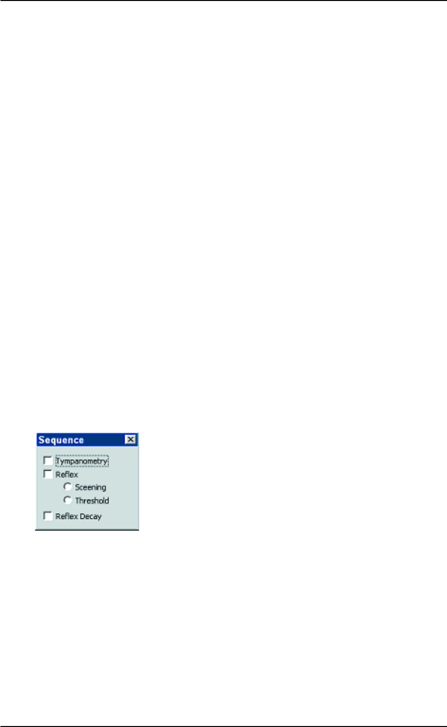
5.3 Sequence setup
You can adjust the sequence and define which tests to perform.
These settings are available in the Measurement Settings dialog
box.
1. Select Main Menu > Tools > Measurement Settings or
click on the Measurement Settings icon on the toolbar.
Click on the Sequence tab.
2. In this dialog box you can define the sequence and the tests to
be included in the sequence.
3. To use the sequence, click on the Sequence radiobutton in
the Autostart field in the control panel on the left side of the
screen, before you start testing.
5.3.1 Procedure options
In the menu item Procedure Opts, you can set the sequence of ac-
tions you want the OTOflex 100 to perform, when you switch on the
device.
Auto start Default: On

52 GN Otometrics A/S
User Manual OTOflex 100
Autonew cl[ient] Default: On
Auto cl[ient] id Default: On
Patient sel[ection] Default: Before
Start ear Default: Right
Default test Default: Tymp
Auto print D Default: Off
Auto print E Default: OFF
Audible seal Default: On
Audible test Default: On
Hide upldd Default: Off
Auto delete Default: Off

OTOflex 100 User Manual
GN Otometrics A/S 53
6 Viewing results
6.1 Viewing all results
1. Press the Select button to access the Main Menu.
2. Scroll to View all results and press Select.
The screen Test Results is shown.
The results are sorted according to the individual patients. For
instance:
Bob Crawford
2003-09-24 8:14
A: Tymp
A: Tymp
A: RThreshold
A: RThreshold
Amelia Davis
2003-10-28 13:15
A: Tymp
A: Tymp
A: RDecay
A: RDecay
3. Scroll to the result you want to view.
4. Press Select to view the result.
6.2 Viewing current results
1. Select the patient, whose results you want to view (see Section
3.3.3, ‘Selecting a patient” on page 28.
2. Press the Select button to access the Main Menu.
3. Scroll to View cur. results and press Select.
The results are sorted according to the test types.

54 GN Otometrics A/S
User Manual OTOflex 100

OTOflex 100 User Manual
GN Otometrics A/S 55
7 Printing results
7.1 Printing a single-page report
1. Press the Select button to access the Main Menu.
2. Scroll to Print report and press Select.
The screen Test Results is shown.
The results are sorted according to the individual patients. For
instance:
Bob Crawford
2003-09-24 8:14
A: Tymp
A: Tymp
A: RThreshold
A: RThreshold
Amelie Davis
2003-10-28 13:15
A: Tymp
A: Tymp
A: RDecay
A: RDecay
3. Scroll to the result you want to print.
4. Press Select to print the result.
7.2 Printing current results
1. Select the patient, whose results you want to print (see Section
3.3.3, ‘Selecting a patient” on page 28.
2. Press the Select button to access the Main Menu.
3. Scroll to Print cur. results and press Select.
The results are sorted according to the test types.

56 GN Otometrics A/S
User Manual OTOflex 100

OTOflex 100 User Manual
GN Otometrics A/S 57
8 Service and Maintenance
8.1 Equipment failure
WARNING:
Do not use a defective instrument.
If you believe the correct function or operation safety of the OTOflex
100 is faulty in any way, disconnect the OTOflex 100 from the power
supply, remove the batteries, and make sure that it cannot be used
by others until it has been serviced.
WARNING:
Under no circumstances disassemble the OTOflex 100. Contact your
supplier.
8.2 Service and repair
WARNING:
Under no circumstances disassemble the OTOflex 100. Contact your
supplier. Parts inside the OTOflex 100 must only be checked or serv-
iced by authorized personnel.
WARNING:
Do not disassemble the OTOflex 100 charger, as there is a risk of elec-
tric shock.
For the sake of safety and in order not to void the warranty, service
and repair of electromedical equipment should be carried out only
by the equipment manufacturer or by service personnel at author-
ised workshops. In case of any defects, make a detailed description
of the defect(s) and contact your supplier.
The manufacturer reserves the right to disclaim all responsibility for
the operating safety, reliability and performance of equipment serv-
iced or repaired by other parties. Following repair, the equipment
should be tested by suitably qualified personnel.
On request, your supplier can obtain a Service Manual from the
manufacturer. The Service Manual contains electrical diagrams, de-
scriptions, lists of components and calibration information, etc.

58 GN Otometrics A/S
User Manual OTOflex 100
8.3 Maintenance
The OTOflex 100 requires no preventive maintenance. However, it is
recommended that you observe the guidelines below.
8.3.1 Calibration
The OTOflex 100 is delivered fully calibrated. The instrument is cal-
ibrated in dB SPL or dB HL using the stated reference equivalent
thresholds. dB HL are related to sound pressure levels, dB SPL = dB
re 20 µPA.
8.3.2 Probe cleaning and maintenance
The probe body Caution:
For periodical cleaning of the probe body, contact your authorized
service department.
The probe tip Note:
Never place the probe tip in the ear canal without using a clean ear-
tip.
The probe tip usually does not come into contact with the skin or se-
cretion from the ear canal, as it is covered by the eartip. However, in
some cases large amounts of cerumen in the ear canal may result in
debris being deposited on the probe tip. If this is the case, clean the
probe tip sound channels with the cleaning wire.
Note:
Check the channels in the probe tip every time you have used the
probe. Even small amounts of cerumen or vernix can block the probe
channels. Clean the channels if required.
Note:
Wipe the plastic probe tip with a disinfectant (for example ethanol)
between patients or replace it with a spare one.
• If you have replaced the probe tip and/or the acoustic filter,
do a probe test (see Section 3.3.1, ‘Probe test” on page 26).
NEVER insert the probe tip into the test cavity of the OTOflex
without first cleaning and disinfecting the probe tip.
8.3.3 Cleaning and disinfecting the probe tip
You should always comply with local hygienic standards for disin-
fection and sterilization.
Thorough cleaning of the probe tip is required after use in infected
ear canals. Cleaning the threaded ring may also be required.
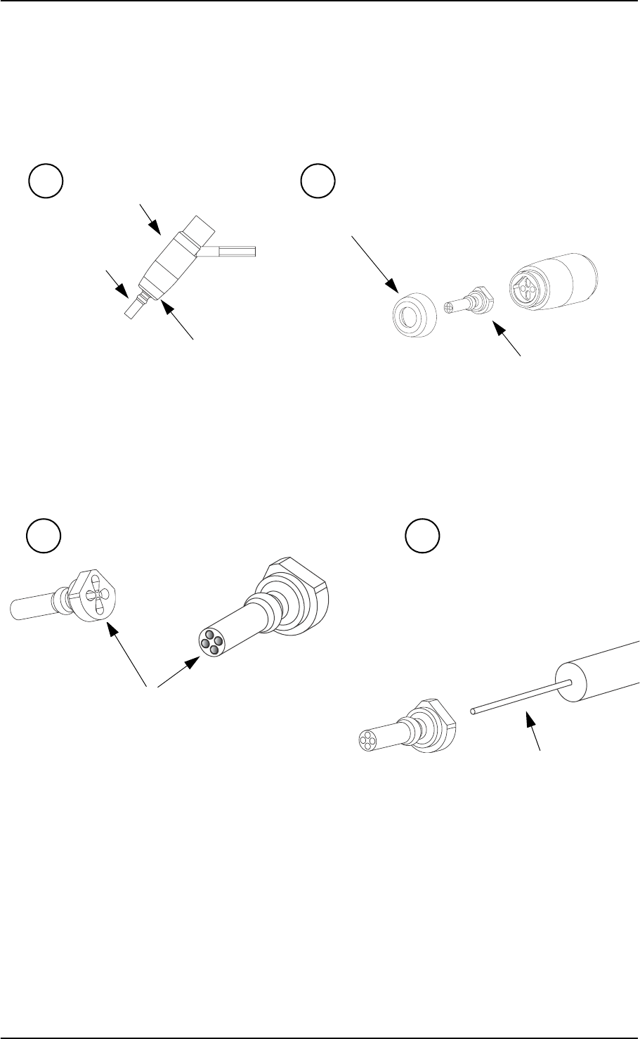
GN Otometrics A/S 59
OTOflex 100 User Manual
1. To remove the probe tip, hold the probe by the probe body and
unscrew the threaded ring. Take out the probe tip.
2. Check to see if the sound channels of the probe tip are blocked.
If they are, use the cleaning wire to clean the sound channels.
Always clean from the rear.
3. If you are cleaning the probe tip during a session where you are
testing a patient, use the cleaning brush to clean the cleaning
wire, especially where it protrudes from the probe tip.
If you are cleaning the probe tip between patients, use disinfect-
ant to clean the cleaning wire, and, if you have used the brush,
Probe body
Probe tip
Threaded ring
Threaded ring
a b
Probe tip
Sound channels
c d
Cleaning wire

60 GN Otometrics A/S
User Manual OTOflex 100
disinfect the brush as well. See Section , ‘Cleaning and disin-
fecting procedures for the probe tip” on page 60.
Caution:
Even the slightest amount of moisture may dissolve any residual
cerumen and thus contaminate the sensitive parts in the body of the
probe.
4. Make sure that the sound channels are completely dry before
you fit the tip back onto the probe body, or use a spare probe
tip.
Caution:
The probe body contains sensitive components. Never clean the sound
channels in the probe body mechanically or with liquids. Doing so
may cause damage to the probe.
5. Fit the probe tip and screw the threaded ring back onto the
probe body.
Cleaning and disinfecting procedures for the probe tip
The probe tip material is highly resistant to a wide range of temper-
ature and chemical influences.
Regular cleaning
• Use a wet tissue for regular surface cleaning.
• Use ultrasonic cleaning to remove contaminants, for instance
before autoclaving.
Disinfecting
You can choose between a number of methods for disinfecting the
probe tip, for instance:
• Immersion of the probe tip in a bath of 70-90% ethyl or isopro-
pyl alcohol for 10-30 minutes contact time.
Cleaning wire

GN Otometrics A/S 61
OTOflex 100 User Manual
• Immersion of the probe tip in a Sodium Hypochlorite solution
at high concentrations and extended contact time (considered
a cold sterilant).
When you have cleaned the probe tip, rinse it thoroughly in regular
water.
Autoclaving
Use autoclaving in accordance with the national standards for va-
pour cleaning with an exposure time of up to 45 minutes at a maxi-
mum temperature of 150°C.
The probe tip is designed to withstand up to 3,000 autoclaving cycles
in which temperatures typically reach 134°C.
Make sure that the probe tip has not been deformed by the autoclav-
ing process.
8.3.4 Cleaning and disinfecting the test cavity
Caution:
The test cavity is located in the charger, which contains electrical
components and mains connection. Therefore: do not use bath or
autoclaving!
If the test cavity has been contaminated with debris from the probe
tip, use gas cleaning according to local hygienic standards (i.e. with
ethyleneoxide, at a temperature of 55°C, at a pressure of 0.8 to 1.0
bar).
8.3.5 Changing the acoustic filter
If you are warned that there is a probe error, or that the probe is not
ok, check whether the probe tip is blocked. If it is not, the acoustic
filter of the probe may be damaged or blocked by cerumen.
If this is the case, change the acoustic filter.
1. To replace the acoustic filter, remove the probe tip (see
‘‘Cleaning and disinfecting the probe tip” on page 58).
2. Use the extraction hook to take out the acoustic filter from the
probe tip.
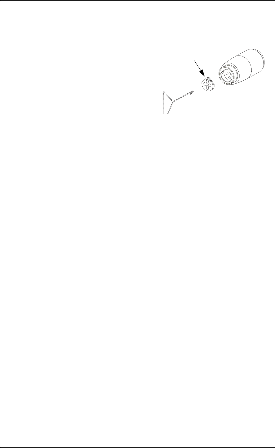
62 GN Otometrics A/S
User Manual OTOflex 100
Note:
Filters are disposables. See Section 8.3.8, ‘Disposal of disposable ar-
ticles” on page 63 for instructions on disposal.
Do not put used filters in the accessory box.
3. Insert a new filter. Be careful not to damage the filter openings.
4. Fit the probe tip over the acoustic filter in the probe body and
and screw the threaded ring back onto the probe body.
8.3.6 Cleaning the OTOflex 100
Prerequisites
• Before cleaning, switch off the OTOflex 100 and disconnect it
from any external power source.
• Dismount the probe from the OTOflex 100.
Regular cleaning
•Clean the OTOflex 100 with a damp cloth - if required, use a
surface disinfectant.
Note:
Never use liquids.
Note:
Always make sure that no moisture enters the probe or the sockets
(charger insert and probe sockets).
Note:
Never immerse the OTOflex 100 into water or other cleaning solu-
tions.
Periodically clean the LCD screen. Use an anti-static non-solvent so-
lution on a lint-free cloth. Use a soft brush to remove dust. Use a
small amount of mild detergent on a damp cloth to clean the cabinet
and front.
Extraction hook
Acoustic filter
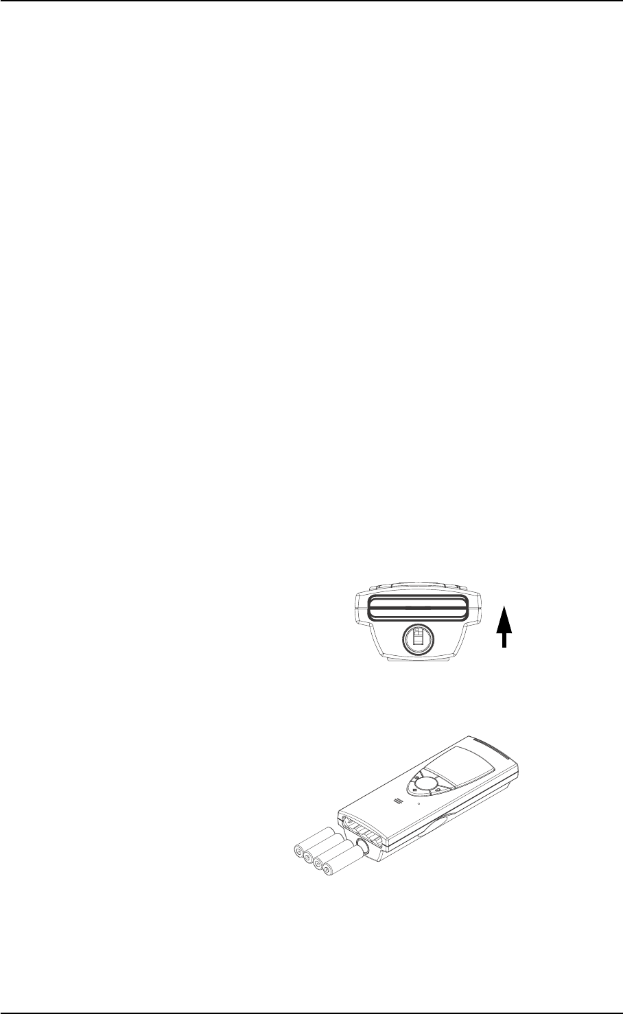
GN Otometrics A/S 63
OTOflex 100 User Manual
8.3.7 Eartips
Eartips
The eartips are in direct contact with your patients, and you should
therefore observe strict hygienic precautions to prevent passing in-
fections from one patient to another. It is therefore recommended
that you use only disposable ear tips.
The OTOflex 100 eartips and foam eartips for the E-A-RTONE 3A in-
sert phone are disposable, and should not be cleaned or re-used. Al-
ways throw away disposable eartips after use on a patient. See
Section 8.3.8, ‘Disposal of disposable articles” on page 63 for instruc-
tions on disposal.
8.3.8 Disposal of disposable articles
Disposable articles (such as ear tips and cleaning wires) should be
disposed of according to local regulations.
8.3.9 Batteries and charger
Note:
For disposal of old batteries, see Section 8.3.11, ‘Environmental pro-
tection” on page 64.
1. To change old batteries press the cover inwards and upwards.
The cover will then slip out of its recess.
2. Insert the batteries as shown.
+
++
+
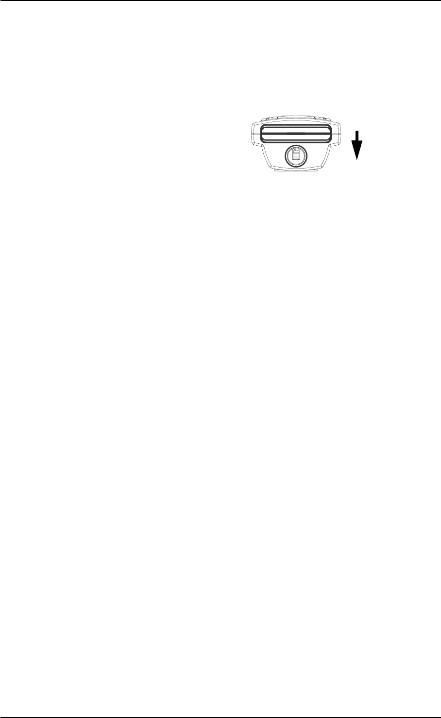
64 GN Otometrics A/S
User Manual OTOflex 100
3. Put the battery cover back in place: Insert the cover with the
curved edge facing upwards in the opening. Press the cover
inwards and downwards until it clicks into place.
8.3.10 Safety information
Explosion hazard
• Do not throw the batteries into the fire and keep them away
from fire as they may explode.
• Incorrect handling, applying excessive charging current can
overcharge or destroy the batteries.
• The battery terminals must under no circumstances be short-
circuited.
• Do not open, alter or dismantle the charger.
8.3.11 Environmental protection
•The OTOflex 100 can be disposed of as normal electronic
waste, according to local regulations.
• Dispose of batteries according to local regulations.

OTOflex 100 User Manual
GN Otometrics A/S 65
9 Troubleshooting
The following table supplies solutions to possible issues you may experience with your OTOflex 100:
Problem Possible cause Solution
OTOflex 100 does not
power on even though I
press the power button.
• The batteries are inserted
incorrectly.
• The batteries need charg-
ing (if rechargeable) or
replacing.
• Insert the batteries correctly.
• Charge the batteries (if
rechargeable) or fit OTOflex
100 with new batteries.
OTOflex 100 powers off
and cannot power on even
though I press the power
button.
The batteries need charg-
ing (if rechargeable) or
replacing.
Charge the batteries (if recharge-
able) or fit OTOflex 100 with new
batteries.
The charging indicator does
not light up when I place
OTOflex 100 in the charger.
• The charger is not con-
nected to the mains sup-
ply.
• There are no batteries in
the OTOflex 100 unit, or
the batteries are inserted
incorrectly.
• Connect the charger to the
mains supply.
• Place batteries in the battery
compartment and make sure
they are inserted correctly.
The discharging indicator
does not light up when I
press the discharging but-
ton.
• The batteries are already
fully discharged.
• The batteries are defect-
ive.
• Charge the batteries (if
rechargeable) .
•Fit OTOflex 100 with new bat-
teries.

66 GN Otometrics A/S
User Manual OTOflex 100
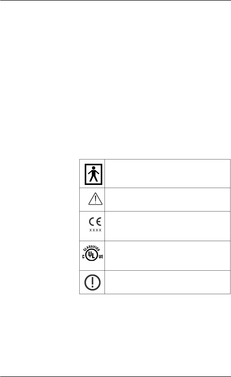
OTOflex 100 User Manual
GN Otometrics A/S 67
10 Safety
This User Manual contains information and warnings, which must
be followed to ensure the safe performance of the OTOflex 100. Local
government rules and regulations, if applicable, should also be fol-
lowed at all times.
10.1 Symbols used
10.1.1 OTOflex 100 symbols
The OTOflex 100 is marked with this symbol to indi-
cate compliance with Type BF of the safety standard
EN 60601-1. See Section 7.16, ‘Standards” on page 42.
The OTOflex 100 is marked with this symbol when it
is important that the user refers to associated informa-
tion given in this manual.
The OTOflex 100 is CE-marked according to the Med-
ical Devices Directive 93/42/EEC and the Radio
Equipment and Telecommunications Terminal Equip-
ment Directive 1999/5/EC.
Classified with respect to electrical shock, fire, me-
chanical and other specified hazards only in accord-
ance with UL2601-1 and CAN/CSA-C22.2 NO 601.1-
90
The OTOflex 100 carries this symbol to indicate that,
in France, it is only permitted to use the device in-
doors.
68 GN Otometrics A/S
User Manual OTOflex 100
10.1.2 Charger unit symbols
This device complies with part 15 of the FCC rules.
Operation is subject to the following two conditions:
1. This device may not cause harmful interference.
2. This device must accept any interference
received, including interference that may cause
undesired operation.
Refer to Notes 5 through 7 in Section 10.2, ‘Warning
notes” on page 69 for more details.
The term”IC”: before the certification/registration
number only signifies that the Industry Canada tech-
nical specifications were met.
Symbols on buttons to operate Otoflex 100, see Sec-
tion 2.6, ‘Display & keypad” on page 21.
The charger unit is marked with this symbol to indi-
cate compliance with Class II requirements of the
safety standard EN 60601-1.
The charger unit is marked with this symbol when it
is important that the user refers to associated informa-
tion given in this manual.
The charger unit is CE-marked according to the Med-
ical Devices Directive 93/42/EEC.
The charger unit is marked with this symbol to indi-
cate it is a UL recognized component for Canada and
the United States.
The charger unit is marked with this symbol to indi-
cate that it is suitable for alternating current only.
GN Otometrics A/S 69
OTOflex 100 User Manual
10.2 Warning notes
10.2.1 OTOflex 100 warning notes
Note 1: There are no user-serviceable parts inside the OTOflex 100 cabinet.
For the sake of safety, and in order not to void the warranty, the cab-
inets should only be opened and serviced by authorized service per-
sonnel. In case of defects, please make a detailed description of the
defect(s) and contact your supplier. Do not use a defective instru-
ment.
Note 2: Keep the OTOflex 100 away from liquids. Do not allow moisture in-
side the instrument.
Note 3: Do not use the instrument in the presence of flammable anesthetics
(gases).
Note 4: Unwanted noise may occur if OTOflex 100 is exposed to a strong ra-
dio field. Such noise may interfere with the process of recording cor-
rect measurements. Many types of electrical devices, e.g. mobile
telephones, may generate radio fields. We recommend that the use
of such devices in the vicinity of OTOflex 100 is restricted as much as
possible.
Note 5: Changes or modifications not expressly approved by the manufac-
turer could void the user's authority to operate the equipment.
Note 6: This equipment has been tested and found to comply with the limits
for a Class B digital device, pursuant to part 15 of the FCC Rules.
The OTOflex 100 should only be provided with pre-
scribed battery types, see Chapter 11, “Technical Spec-
ifications” on page 73.
Place the batteries as indicated in the battery compart-
ment, see Section 2.5.2, ‘Powering the OTOflex 100”
on page 16 for further details.
Use only rechargeable batteries when OTOflex 100 is
placed in the charger unit. If you are using alkaline
batteries, do not attempt to charge your OTOflex 100.
Your alkaline batteries may be damaged and leak, and
this may in turn cause damage to OTOflex 100.
Batteries should be removed if equipment is not likely
to be used for some time.
The OTOflex 100 should only be connected to charger
type 1012 Charger from GN Otometrics A/S.

70 GN Otometrics A/S
User Manual OTOflex 100
These limits are designed to provide reasonable protection against
harmful interference in a residential installation. This equipment
generates, uses and can radiate radio frequency energy and, if not
installed and used in accordance with the instructions, may cause
harmful interference to radio communications. However, there is no
guarantee that interference will not occur in a particular installation.
If this equipment does cause harmful interference to radio or televi-
sion reception, which can be determined by turning the equipment
off and on, the user is encouraged to try to correct the interference
by one or more of the following measures:
• Reorient or relocate the receiving antenna.
• Increase the separation between the equipment and receiver.
• Connect the equipment into an outlet on a circuit different
from that to which the receiver is connected.
• Consult the dealer or an experienced radio/TV technician for
help.
Note 7: For use in Canada: To prevent radio interference to the licensed serv-
ice, this device is intended to be operated indoors and away from
windows to provide maximum shielding. Equipment (or its trans-
mit antenna) that is installed outdoors is subject to licensing.
Note 8: No parts may be eaten, burnt, or in any way used for purposes other
than audiometry or the fitting of hearing aids.
Note 9: OTOflex 100 can be disposed of as normal electronic waste, accord-
ing to local regulations. Please investigate local regulations concern-
ing the disposal of rechargeable and alkaline batteries.
Note 10: For safety reasons, accessories connected to the equipment's outlet
fittings must be identical to the type supplied with the system.
Note 11: It is recommended that an annual calibration be performed on acces-
sories containing transducers. Furthermore, it is recommended that
calibration be performed if the equipment has suffered any potential
damage (e.g. transducers dropped on the floor). Note that calibra-
tion has been performed only on the transducers supplied! If you
wish to use any other transducer for testing with the OTOflex 100,
please contact your local supplier.
Note 12 Choking hazard! Do not leave eartips unsupervised within the reach
of children.
GN Otometrics A/S 71
OTOflex 100 User Manual
10.2.2 Charger unit warning notes
Note 1: There are no user-serviceable parts inside the charger unit cabinet.
For the sake of safety, and in order not to void the warranty, the cab-
inets should only be opened and serviced by authorized service per-
sonnel. In case of defects, please make a detailed description of the
defect(s) and contact your supplier. Do not use a defective instru-
ment.
Note 2: The charger unit can be disposed of as normal electronic waste, ac-
cording to local regulations.
10.3 Manufacturer
GN Otometrics A/S
2 Dybendalsvaenget, DK-2630 Taastrup, Denmark
Phone: +45 72 111 555, Fax: +45 72 111 548
E-mail: info@gnotometrics.dk
www.gnotometrics.com
10.3.1 Responsibility of the manufacturer
The manufacturer is to be considered responsible for effects on safe-
ty, reliability, and performance of the equipment ONLY IF:
• All assembly operations, extensions, re-adjustments, modifica-
tions or repairs are carried out by the equiment manufacturer
personnel authorised by the manufacturer.
• The electrical installation to which the equipment is connected
complies with EN/IEC requirements.
• The equipment is used in accordance with the instructions for
use.
The manufacturer reserves the right to disclaim all responsibility for
the operating safety, reliability and performance of equipment serv-
iced or repaired by other parties.
In order to disconnect the charger unit from mains the
power cable must be detached from the power source.

72 GN Otometrics A/S
User Manual OTOflex 100

OTOflex 100 User Manual
GN Otometrics A/S 73
11 Technical Specifications
11.1 Otoflex 100
11.1.1 Compliance measuring system
Probe tone: 226Hz @ 85dBspl ± 1.5dB
1000Hz @ 75dBspl ± 1.5dB
THD: < 3% in 2 cc
Frequency Accuracy: +/-0.5%
Range: 0.1 ml to 8.0 ml ± 5% or 0.1 ml whichever is greater
11.1.2 Acoustic Reflex
11.1.2.1 Contra lateral Stimulation
Pure tones: 500Hz, 1000Hz, 2000Hz, 3000Hz, 4000Hz
Frequency Accuracy: ± 0.5%
Noise White Noise
Low Pass 400 to 1600 Hz
High Pass 1600 to 4000 Hz
Roll off >12 dB/Octave
Range 50-105 dB HL ± 3 dB
Step size dB 1, 2, 5, 10 dB
E-A-RTONE 3A:
Normal range: 50-100 dB HL ± 3 dB
Extended range: 50-120 dB HL ± 3 dB

74 GN Otometrics A/S
User Manual OTOflex 100
Probe:
Normal range: 50-100 dB HL ± 3 dB
Extended range: 500 Hz, 1000 Hz, 2000 Hz, 4000 Hz 50 to 110 dB HL ± 3 dB
THD: < 3% in 2 cc
11.1.2.2 Ipsilateral Stimulation
Tone: 500Hz, 1000Hz, 2000Hz, 3000Hz, 4000Hz
Frequency Accuracy: ± 0.5%
Noise White Noise
Low Pass 400 to 1600 Hz
High Pass 1600 to 4000 Hz
Roll off >12 dB/Octave
Range 50-105 dB HL ± 3 dB
Step size dB: 1, 2, 5, 10 dB
Range at: 500 Hz, 1000 Hz, 2000 Hz 50 to 110 dB HL ± 3 dB
4000 Hz 50 to 100 dB HL ± 3 dB
THD: < 3% in 2 cc
11.1.3 Air pressure system
Range: Normal +200 to -400 daPa/s,
Extended +400 to -600 daPa/s
Pump speed: 50, 100, 200, 400 daPa/s, A.F.A.P and manual pressure
control
A.F.A.P. will start at 500 daPa/s and slow down to 400
daPa/s, when a peak is detected.
Manual pump speed operates in the range 5 to 25 daPa/s
Accuracy: ±10% or ±10 daPa
Pump measure direction: Automatic Tymp sweep Normal positive to negative
Safety: Separate pressure release activated at +600 daPa and
-800 daPa
11.1.4 Data interface
Wireless Bluetooth data transfer to PC
Wireless Bluetooth printing to a printer complying with HP PCL 5

GN Otometrics A/S 75
OTOflex 100 User Manual
11.1.5 Type identification
Otoflex 100 is type 1012 from GN Otometrics A/S
11.1.6 Power supply
Battery types: Rechargeable (Ni-MH type) AA (R6) 1.2V, 4 pcs. (4.8V)
Use only rechargeable batteries supplied by GN Otomet-
rics A/S
Alkaline AA (R6) 1.5V, 4 pcs. (6.0V)
Battery supply voltage: Nom. 5 V, max. 6.4 V, min. 4.0 V (instrument power off
voltage)
Low battery indicator level: The following battery indications apply:
- Charging
- Fully charged (100%)
- Medium (60%)
- Low (30%)
- Discharged (0%)
Estimated battery life: The device is able to handle a working day (8 hours) with
normal audiological use on fully charged batteries. This
also applies to alkaline batteries.
11.1.7 Dimensions and weight
OTOflex 100 dimensions: H: 19.9 cm
W: 7.7 cm
D: 4.8 cm
Weight: OTOflex 100, incl. batteries: 615 g
OTOflex 100 cap: 25 g
11.2 Charger unit
11.2.1 Type identification
Charger unit is type 1012 Charger from GN Otometrics A/S
11.2.2 Power supply
Input voltage: 100 - 240 VAC, 50/60 Hz
Power consumption < 10 VA

76 GN Otometrics A/S
User Manual OTOflex 100
11.2.3 Dimensions and weight
Dimensions, without base plate:H: 17.9 mm
W: 7.7 mm
D: 4.8 mm
Weight: Charger without base plate: 230 g
Charger base plate: 366 g
11.3 Operating mode
Mode of operation: Continuous
Warm-up time: < 2 min.
11.4 Operating environment
Temperature: +10°C to +35°C
Air Humidity: 30 to 90%, non-condensing
Air Pressure: 600 hPa to 1060 hPa
Operation at temperatures below -20°C or above +60°C may cause permanent damage.
11.5 Transport and storage
Temperature: -20°C to +60°C
Air Humidity: < 90%, non-condensing
Air Pressure: 500 hPa to 1060 hPa
11.6 Miscellaneous
2cc coupler for probe check
Date and time for measurement log
Graphic display, 128x128 dots

GN Otometrics A/S 77
OTOflex 100 User Manual
11.7 Standards
Safety: EN 60601-1, UL 2601-1, CAN/CSA -C22.2 NO 601.1-90
Otoflex 100: EN 60601-1, Class II, Internal Powered, Type
BF, IPX0
Charger unit: EN 60601-1, Class II, IPX0
EMC: EN 60601-1-2, EN 300 328-2, EN 301 489-17
Impedance/Admittance: EN 61027 Type 1, ANSI S3.39 Type 1
11.8 Standard and optional accessories
Standard
1 OTOflex 100 w/built-in Bluetooth interface
1 Charger/cradle w/2cc cavity and straight power cable
1 Immittance probe w/wax filter kit and cleaning kit, select probe type in E
1 Eartip start kit: large box filled with eartip selection
1 Handy eartip box (empty)
1 CD with OtoDiagnostic Suite
1 Bluetooth USB adapter for PC
1 Quick Guide, paper copy (7-50-0060x), select language in A
1 Probe cap for mounting on top of device
4 Rechargeable NiMH batteries (1pcs)
1 Immittance probe
Diagnostic
E-A-RTONE 3A contra insert phone w/eartips
Shoulder harness kit

78 GN Otometrics A/S
User Manual OTOflex 100

OTOflex 100 User Manual
GN Otometrics A/S 79
12 Glossary
12.1 Clinical Terminology
Air Conduction (AC) Sound transmitted through air.
Acoustic Reflex (AR) Reflexive concentration of the intra-aural muscles in response to
loud sound, dominated by the stapedius muscle in humans
Acoustic reflex decay Perstimulatory reduction in the magnitude of the acoustic reflex,
considered abnormal if it is reduced by over 50% of initial amplitude
within 10 seconds of stimulus onset.
ANSI American National Standards Institute
Audiogram A chart or graph of the results of a hearing test conducted with au-
diographic equipment. The chart reflects the softest (lowest volume)
sounds that can be heard at various frequencies or pitches.
Audiometry Audiometry is the testing of a person's ability to hear various sound
frequencies. The test is performed with the use of electronic equip-
ment called an audiometer. This testing is usually administered by a
trained technician called an audiologist.
Bone Conduction (BC) Sound transmitted through the bone.
Click Evoked Response Audiometry (ERA) is an electrical response to
acoustical stimulus, usually a Click or a Tone Burst. A click stimulus
is typically a short duration and transient sound, usually a square
wave with a width of 100 microseconds. Click stimuli can be charac-
terized by 4 integers: Polarity (condensation, rarefaction, or alternat-
ing) , click type, duration and stimulus delay.
Calibration Electroacoustic or psychoacoustic determination that an electrical
device (such as an amplifier) or an acoustic transducer (an ear-
phone) is performing properly according to (defined) characteristics
in terms of its acoustic output, attenuator linearity, frequency accu-
racy, harmonic distortion, etc.
Decibel Tenth of a Bel, a unit for expressing the ratio between two sound
pressures or two sound powers. Normal speech is typically spoken
in the range of about 20-50 decibels.

80 GN Otometrics A/S
User Manual OTOflex 100
dB HL (hearing level) Decibel scale referenced to accepted standards for normal hearing
(0 dB is average normal hearing for each audiometric test frequen-
cy).
dB nHL (normalized hearing level) Decibel scale used in auditory brain stem response measurement
referenced to average behavioral threshold for the click or tone burst
stimulus of a small group of normal hearing subjects.
dB SPL (sound pressure level) Decibel scale referenced to a physical standard for intensity (e.g., 20
mPa or 0.0002 dynes/cm2).
Diagnostic Refers to measurements of a patient's hearing impairment as part of
a medical assessment and treatment.
Earphone An earphone is a transducer that converts electrical energy to acous-
tic energy.
Evoked Response Audiometry
(ERA)
Also known as auditory electro-physiology. Various ERA methods
record Auditory Evoked Potentials (AEP) originating from different
locations along the auditory pathway. The Audiometric methods
can be subdivided as follows: Electrocochleography (ECoG) meas-
uring the auditory peripheral activity, Brain Stem Response Audi-
ometry (BRA), and Cortical Response Audiometry (CRA).
Frequency Number of cycles occurring per unit of time. The frequency is the re-
ciprocal of the period. The unit is the cycle per second (cps) or Hz.
HL (Hearing Level) Lowest intensity level that a person can hear a sound of a particular
frequency; represented as the number of decibels above an average
normal hearing threshold for any given signal. 0 dB HL is equivalent
to normal hearing.
High pass filter Filter that passes electrical energy above a specific cutoff frequency
and eliminates (filters out) energy below that frequency. A typical
high-pass filter setting (which is at the lower end of the frequency
range being filtered) in ABR measurement is 50 Hz.
Hearing Instrument (HI) A device that is amplifying acoustic and/or inductive (telecoil) sig-
nals for presentation in a (hearing impaired) ear.
Hearing Instrument Specialist
(HIS)
Health information system; computer database system designed
specially for healthcare institutions for information processing of
patient demographic data, diagnosis, payer source, etc.
Hearing Instrument Test (HIT) Is a series of measurements carried out on a hearing instrument.
Typical measurments are: frequency response, distortion, attack/re-
lease, input/output The hearing instrument is typically tested inside
a test chamber to allow quiet surroundings for the tests. The hearing
instrument's output is usually connected to a coupler that has a
built-in microphone for capturing of the output of the hearing in-
strument. Some test sequences are defined by IEC 118 and ANSI 3.22
test standards.

GN Otometrics A/S 81
OTOflex 100 User Manual
Intensity Amount of sound energy per unit area.
Normative data Statistical information on normal characteristics of data, such as
AER latency, amplitude values, or expected threshold intensity level
for the response.
Immittance audiometry Battery of immittance measurements, including static immittance,
tympanometry, and acoustic reflex threshold determination, de-
signed to assess middle ear function.
Impedance audiometry See Immittance audiometry
Masking A constant level of background noise presented to the non-test ear
in an audiometric procedure or AER measurement. Masking is used
in an attempt to prevent a response from the nontest ear due to pos-
sible stimulus crossover from the test ear.Otoacoustic Emission
(OAE)
Noise (acoustic) any undesired sound or disturbance within a useful fre-
quency band, such as undesired electric waves in a transmission
channel or device. (bioelectric) in evoked response measurement,
noise is unwanted activity, either electrical or muscular, which inter-
feres with detection of the response.
Noise can also be a signal type, e.g. narrow band noise or wide band
noise with a specified spectrum
Otolaryngologist Physician specializing in the medical and surgical treatment of dis-
orders in the ear, nose and throat.
Otoscope A hand-held instrument with a tiny light and a funnel-shaped at-
tachment called an ear speculum, which is used to examine the ear
canal and eardrum.
Patient The person that will undergo an examination. In this manual, the
term also covers the term “Client”.
Probe tone
Real Ear Measurement (REM) Measurements that are assisting the operator of the REM equipment
in adjusting the hearing instrument so that the sound presented by
the hearing instrument (frequency response / output level) is appro-
priate for the hearing impairment of that particular patient. During
traditional REM a signal is presented in a loudspeaker, the signal
right outside and inside the ear is picked up by two microphones. A
measurement curve (typically output or gain) is displayed on the
REM equipment for comparison with one or more target curves. The
target curves are based on audiometry data.
Smooth (smoothing) Digital manipulation of a waveform in which voltages for a se-
quence of three or more data points are added together. Smoothing
may reduce the noisy appearance of waveforms containing exces-

82 GN Otometrics A/S
User Manual OTOflex 100
sive high-frequency electrical activity and may facilitate identifica-
tion of major wave components.
Sound Level Meter Device for measuring the intensity level of sound waves in air; the
unit of measurement is in decibels sound pressure level (SPL dB).
Tympanometry (Tymp) Procedure used in the assessment of middle ear function in which
the immittance of the tympanic membrane and middle ear is meas-
ured as air pressure delivered to the ear canal is varied.
Transducer Electronic component transforming e.g. an electrical signal into
sound, sound into an electrical signal, or a pressure into a voltage.
Tone Sinusoid or steady-state (ongoing) sound of a single-frequency (vs.
noise with many frequencies or a click).
Tone Burst Evoked Response Audiometry (ERA) is an electrical response to
acoustical stimulus, usually a Click or a Tone Burst. A Tone Burst is
a sinusoid or steady-state (ongoing) sound of a single-frequency (vs.
noise with many frequencies or a click). Tone bursts can be defined
by 4 parameters: RiseTime, DecayTime, Duration and StimDelay.
Intelligent transducer A transducer bundled with a memory containing the transducer's
calibration data and history.