GOODMAN Package Units(both Units Combined) Manual L0806745
User Manual: GOODMAN GOODMAN Package Units(both units combined) Manual GOODMAN Package Units(both units combined) Owner's Manual, GOODMAN Package Units(both units combined) installation guides
Open the PDF directly: View PDF ![]() .
.
Page Count: 33
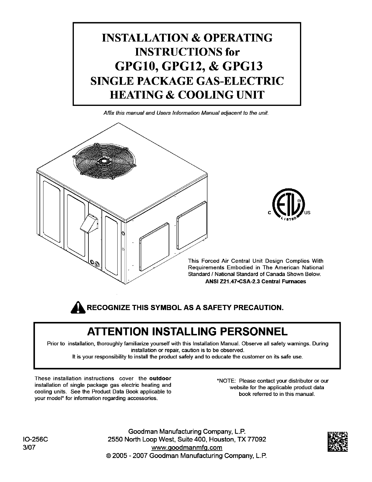
INSTALLATION & OPERATING
INSTRUCTIONS for
GPG10, GPG12, & GPG13
SINGLE PACKAGE GAS-ELECTRIC
HEATING & COOLING UNIT
Affix this manual and Users Information Manual adjacent to the unit.
This Forced Air Central Unit Design Complies With
Requirements Embodied in The American National
Standard /National Standard of Canada Shown Below.
ANSI Z21.47.CSA-2.3 Central Furnaces
_RECOGNIZE THIS SYMBOL AS A SAFETY PRECAUTION.
ATTENTION INSTALLING PERSONNEL
Prior to installation, thoroughly familiarize yourself with this Installation Manual. Observe all safety warnings. During
installation or repair, caution is to be observed.
It is your responsibility to install the product safely and to educate the customer on its safe use.
These installation instructions cover the outdoor
installation of single package gas electric heating and
cooling units. See the Product Data Book applicable to
your model* for information regarding accessories.
*NOTE: Please contact your distributor or our
website for the applicable product data
book referred to in this manual.
IO-256C
3/07
Goodman Manufacturing Company, L.P.
2550 North Loop West, Suite 400, Houston, TX 77092
www.qoodmanmfq.com
©2005 - 2007 Goodman Manufacturing Company, L.P.
INDEX
Replacement Parts ............................................................................................................................................................. 3
ORDERING PARTS .............................................................................................................................................. 3
Safety Instructions ............................................................................................................................................................. 3
Unit location ........................................................................................................................................................................ 4
ALL INSTALLATIONS: ........................................................................................................................................... 4
GROUND LEVEL INSTALLATIONS ONLY: .................................................................................................................. 4
ROOFTOP INSTALLATIONS ONLY: ........................................................................................................................... 4
ROOF CURB INSTALLATIONS ONLY: ....................................................................................................................... 5
General Information ........................................................................................................................................................... 5
TRANSPORTATION DAMAGE .................................................................................................................................. 5
Rigging Details ................................................................................................................................................................... 6
gas piping ........................................................................................................................................................................... 6
HIGH ALTITUDE DERATE (U.S. INSTALLATIONS ONLY) ............................................................................................ 6
PIPING ............................................................................................................................................................. 6
GAS PIPING CHECKS .......................................................................................................................................... 7
Propane Gas Installations .................................................................................................................................................. 7
TANKS AND PIPING ............................................................................................................................................. 8
Electrical Wiring ................................................................................................................................................................. 8
THERMOSTAT LOCATION ...................................................................................................................................... 8
UNIT VOLTAGE .................................................................................................................................................. 9
HEATANTICIPATOR SETTING ................................................................................................................................ 9
Circulating Air and Filters ................................................................................................................................................ 10
AIRFLOW CONVERSION ..................................................................................................................................... '10
DUCTWORK ..................................................................................................................................................... 10
FILTERS .......................................................................................................................................................... '10
Venting .............................................................................................................................................................................. t0
FLUE HOOD INSTALLATION ................................................................................................................................. 10
Condensate Drain ............................................................................................................................................................. tl
CONDENSATE DRAIN CONNECTION ...................................................................................................................... 11
normal sequences of operation ...................................................................................................................................... 11
HEATING ......................................................................................................................................................... 1t
COOLING ........................................................................................................................................................ 1t
FAN ONLY ...................................................................................................................................................... 11
Startup, Adjustments, and Checks .................................................................................................................................. 12
HEATING STARTUP ........................................................................................................................................... 12
COOLING STARTUP ........................................................................................................................................... 15
Troubleshooting ............................................................................................................................................................... 15
IGNITION CONTROL ERROR CODES ..................................................................................................................... 15
ABNORMAL OPERATION -HEATING ................................................................................................................... 15
ABNORMAL OPERATION - COOLING ................................................................................................................... 16
Maintenance ...................................................................................................................................................................... t6
FILTER REPLACEMENT OR CLEANING ................................................................................................................... 16
CABINET FINISH MAINTENANCE .......................................................................................................................... 16
CLEAN OUTSIDE COIL (QUALIFIED SERVICER ONLY) ............................................................................................ 16
CONDENSER, EVAPORATOR, AND INDUCED DRAFT MOTORS ................................................................................... 16
FLAME SENSOR (QUALIFIED SERVICER ONLY) ...................................................................................................... 16
FLUE PASSAGES (QUALIFIED SERVICER ONLY) ..................................................................................................... 16
CLEANING FLUE PASSAGES (QUALIFIED SERVICER ONLY) ...................................................................................... 17
MAIN BURNER FLAME (QUALIFIED SERVICER ONLY) ............................................................................................. 17
CLEANING BURNERS ........................................................................................................................................ 17
Accessories and Functional Parts .................................................................................................................................. t8
SHEET METAL ACCESSORIES ............................................................................................................................. 18
FUNCTIONAL PARTS ......................................................................................................................................... '18
GENERAL INFORMATION ..................................................................................................................................... '18
Ignition Control Diagnostic Indicator Chart ................................................................................................................... t9
Heating Timing Chart ....................................................................................................................................................... 19
Cooling Timing Chart ....................................................................................................................................................... t9
APPENDIX ......................................................................................................................................................................... 20
Unit Dimensions ............................................................................................................................................................... 20
Wiring Diagrams ............................................................................................................................................................... 21
Minimum Clearances ........................................................................................................................................................ 33
Recommended Filter Sizes .............................................................................................................................................. 33
2
REPLACEMENT PARTS
ORDERING PARTS
When reporting shortages or damages, or ordering repair
parts, give the complete unit model and serial numbers as
stamped on the unit's nameplate.
Replacement parts for this appliance are available through your
contractor or local distributor. For the location of your nearest
distributor, consult the white business pages, the yellow page
section of the local telephone book or contact:
SERVICE PARTS DEPARTMENT
GOODMAN MANUFACTURING COMPANY, L.E
2550 NORTH LOOP WEST, SUITE 400
HOUSTON, TEXAS 77092
(713) 861 2500
SAFETY INSTRUCTIONS
TO THE INSTALLER
Before installing this unit, please read this manual to familiarize
yourself on the specific items which must be adhered to,
including maximum external static pressure to unit, air
temperature rise, minimum or maximum CFM and motor
speed connections.
Keep this literature in asafe place for future reference.
A']k WARNING
IF THE INFORMATION IN THESE INSTRUCTIONS IS NOT FOLLOWED EXACTLY, A
FIRE OR EXPLOSION MAY RESULT CAUSING PROPERTY DAMAGE, PERSONAL
INJURY OR LOSS OF LIFE.
Do NOT STORE OR USE GASOLINE OR OTHER FLAMMABLE VAPORS AND
LIQUIDS IN THE VICINITY OF THIS OR ANY OTHER APPLIANCE
WHAT TO DO IF YOU SMELL GAS:
•Do NOT TRY TO LIGHT ANY APPLIANCE
• Do NOT TOUCH ANY ELECTRICAL SWITCH; DO NOT USE ANY
PHONE IN YOUR BUILDING
• IMMEDIATELY CALL YOUR GAS SUPPLIER FROM A NEIGHBOR'S
PHONE FOLLOW THE GAS SUPPUER'S INSTRUCTIONS
• IF YOU CANNOT REACH YOUR GAS SUPPLIER, CALL THE FIRE
DEPARTMENT
INSTALLATION AN D SERVICE MUST BE PERFORMED BY A QUALIFIED INSTALLER,
SERVICE AGENCY OR THE GAS SUPPLIER
IWARNING ]
SHOULD OVERHEATING OCCUR OR THE GAS SUPPLY FAIL TO SHUT OFF, TURN I
E ERNALTOTHEFURNACEBEFOREI
_]_WARNING
THIS PRODUCT CONTAINS OR PRODUCES A CHEMICAL OR CHEMICALS WHICH
MAY CAUSE SERIOUS ILLNESS OR DEATH AND WHICH ARE KNOWN TO THE
STATE OF CALIFORNIA TO CAUSE CANCER, BIRTH DEFECTS OR OTHER
REPRODUCTIVE HARM.
_WARNING
HEATING UNIT SHOULD NOT BE UTILIZED WITHOUT REASONABLE, ROUTINE,
INSPECTION, MAINTENANCE AND SUPERVISION. IF THE BUILIDNG IN WHICH AN_
SUCH DEVICE IS LOCATED WILL BE VACANT, CARE SHOULD BE TAKEN THAT
SUCH DEVICE IS ROUTINELY INSPECTED, MAINTAINED AND MONITORED. IN THE
EVENT THAT THE BUILDING MAYBE EXPOSED TO FREEZING TEMPERATURES
AND WILL BE VACANT, ALL WATER-BEARING PIPES SHOULD BE DRAINED, THE
BUILDING SHOULD BE PROPERLY WINTERIZED, AND THE WATER SOURCE
CLOSED. IN THE EVENT THAT THE BUILDING MAY BE EXPOSED TO FREEZING
TEMPERATURES AND WILL BE VACANT, ANY HYDRONIC COIL UNITS SHOULD
BE DRAINED AS WELL AND, IN SUCH CASE, ALTERNATIVE HEAT SOURCES
SHOULD BE UTILIZED.
_WARNING
TO AVOID PROPERTY DAMAGE, PERSONAL INJURY OR DEATH, DO NOT USE
THIS UNIT IF ANY PART HAS BEEN UNDER WATER. IMMEDIATELY CALL A
QUALIFIED SERVICE TECHNICIAN TO INSPECT THE FURNACE AND TO REPLACE
ANY PART OF THE CONTROL SYSTEM AND ANY GAS CONTROL HAVING BEEN
UNDER WATER.
_WARNING
THIS UNIT MUST NOT BE USED AS A "CONSTRUCTION HEATER" DURING THE
FINISHING PHASES OF CONSTRUCTION ON A NEW STRUCTURE. THIS TYPE OF
USE MAY RESULT IN PREMATURE FAILURE OF THE UNIT DUE TO EXTREMELY
LOW RETURN AIR TERMPERATURES AND EXPOSURE TO CORROSIVE OR VERY
DIRTY ATMOSPHERES.
I&WA.NI.G %.1. 1
.o.vo,,AOE ) 1111
DISCONNECTALL POWER BEFORE SERVICING OR _lk¢_
INSTALLING THIS UNIT. MULTIPLE POWER SOURCES BA_
BE PRESENT. FAILURE TO DO SO MAY CAUSE PROPERTY
DAMAGE IPERSONAL INJURY OR DEATH.
_'_ WARNING
TO PREVENT THE RISK OF PROPERTY DAMAGE, PERSONAL INJURY
OR DEATH, DO NOT STORE COMBUSTIBLE MATERIALS OR USE
GASOLINE OR OTHER FLAMMABLE LIQUIDS OR VAPORS IN THE
VICINITY OF THE APPLIANCE.
I_WARNING
INSTALLATION AND REPAIR OF THIS UNIT SHOULD BE PERFORMED
ONLY BY INDIVIDUALS MEETING THE REQUIREMENTS OF AN ENTRY
LEVEL TECHNICIAN AS SPECIFIED BY THE AIR CONDmDNING AND
REFRIGERATION INSTITUTE (ARI).ATTEMPTING TO INSTALL OR
REPAIR THIS UNIT WITHOUT SUCH BACKGROUND MAY RESULT IN
PRODUCT DAMAGE, PERSONAL INJURY, OR DEATH.
3
CARBON MONOXIDE POISONING HAZARD
SpecialWarningfurInsfulla6onofFumacasorAirHandlingUnitsin
EndosedAreassuchasGarages,UtilityRoomsorParkingAreas
Carbonr_ono:ddeprodudngdevices(suchasanautomobile,space
heater,gaswaterheater,etc.)shouldnotbeoperatedinendosedareas
suchasunventilatedgarages,ubltiyroomsorparkingareasbecauseof
thedangerofcarbonmonoxide(CO)poisoningresultingfromtheexhaust
emissions.Ifafurnaceorairhandierisinstalledinanendosodareasuch
asagarage,utilityroomor parkingareaandacarbonmonoxidepmdudng
deviceisoperatedtherein,theremustbeadequate,directoutside
venblution.
ThisventilationisnecassaP/toavoidthedangerofCOpoisoningwhich
canoccurifacarbonmonoxideproducingdevicecontinuestooperatein
theenclosedarea.Carbonmono_deemissionscanbe(re)circulated
throughoutthes_uctureif fie furnaceorairhandlerisoperatinginany
mode.
COcancausesepeusillnessincludingpermanentbraindamageordeath.
B10259 216
UNIT LOCATION
I_WARNING
To PREVENT POSSIBLE EQUIPMENT DAMAGE, PROPERTY DAMAGE, PERSONAL
INJURY OR DEATH, THE FOLLOWING BULLET POINTS MUST BE OBSERVED
WHEN INSTALLING THE UNIT.
IMPORTANT NOTE: Remove wood shipping rails prior to instal-
lation of the unit.
ALL INSTALLATIONS:
For proper flame pattern within the heat exchanger and
proper condensate drainage, the unit must be mounted
level.
The flue outlet hood must be at least 12 inches from any
opening through which flue gases could enter a building,
and at least three feet above any forced air inlet located
within ten feet. The economizer/manual fresh air intake/
motorized fresh air intake and combustion air inlet
mounted on the unit are not affected by this restriction.
To avoid possible corrosion of the heat exchanger, do not
locate the unit in an area where the outdoor air (i.e.
combustion air for the unit)will be frequently contaminated
by compounds containing chlorine or fluorine. Common
sources of such compounds include swimming pool
chemicals and chlorine bleaches, paint stripper,
adhesives, paints, varnishes, sealers, waxes (which are
not yet dried) and solvents used during construction and
remodeling. Various commercial and industrial processes
may also be sources of chlorine/fluorine compounds.
To avoid possible illness or death of the building occupants,
do NOT locate outside air intake device (economizer,
manual fresh air intake, motorized fresh air intake) too close
to an exhaust outlet, gas vent termination, or plumbing vent
outlet. For specific distances required, consult local codes.
Allow minimum clearances from the enclosure for fire
protection, proper operation, and service access (see
appendix). These clearances must be permanently
maintained.
The combustion air inlet and flue outlet hoods on the unit
must never be obstructed. If used, do not allow the
economizer/manual fresh air damper/motorized fresh air
damper to become blocked by snow or debris. In some
climates or locations, it may be necessary to elevate the
unit to avoid these problems.
When the unit is heating, the temperature of the return air
entering the unit must be between 50 ° F and 100° F.
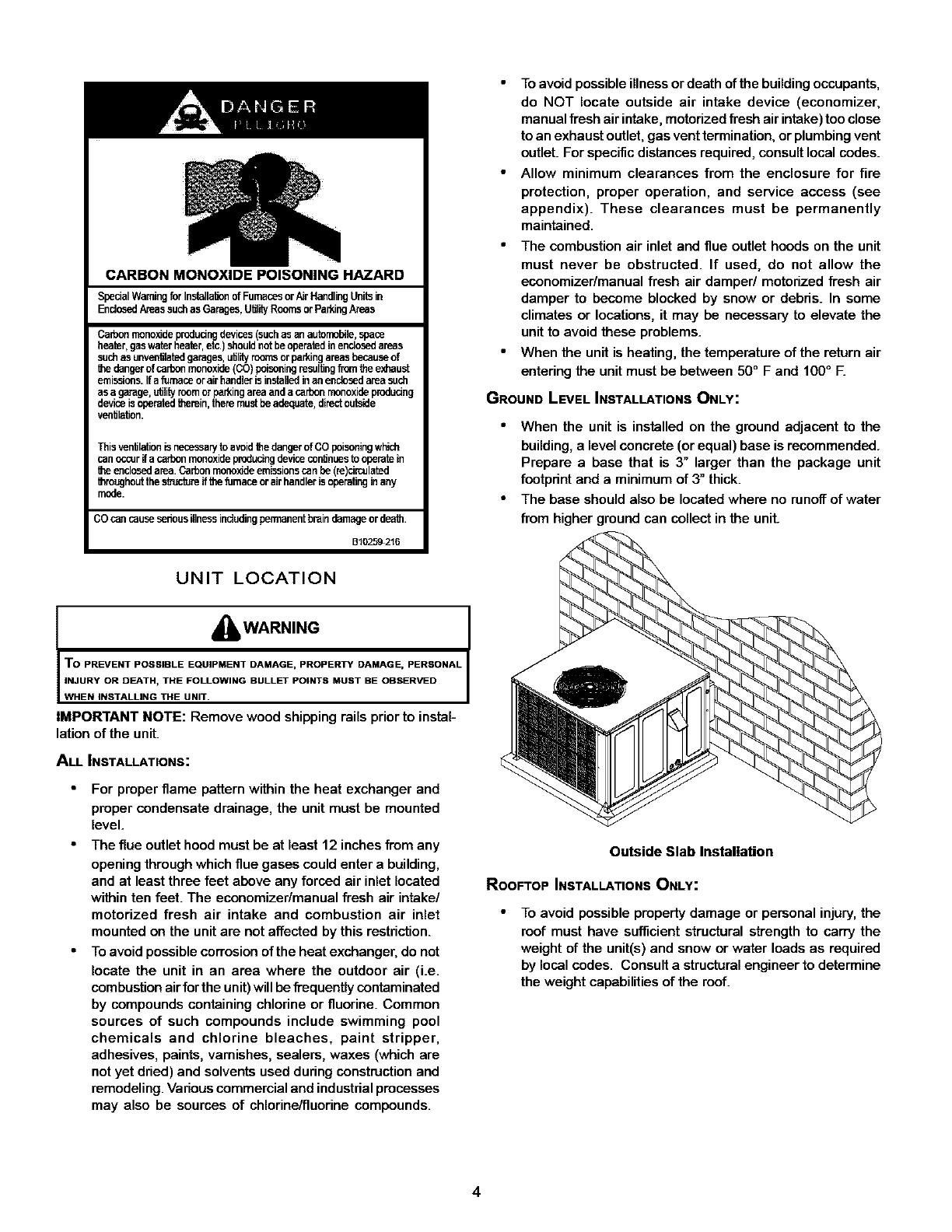
GROUND LEVEL INSTALLATIONSONLY:
When the unit is installed on the ground adjacent to the
building, a level concrete (or equal) base is recommended.
Prepare a base that is 3" larger than the package unit
footprint and a minimum of 3" thick.
The base should also be located where no runoff of water
from higher ground can collect in the unit.
Outside Slab Installation
ROOFTOP INSTALLATIONS ONLY:
To avoid possible property damage or personal injury,the
roof must have sufficient structural strength to carry the
weight of the unit(s) and snow or water loads as required
by local codes. Consult a structural engineer to determine
the weight capabilities of the roof.
4
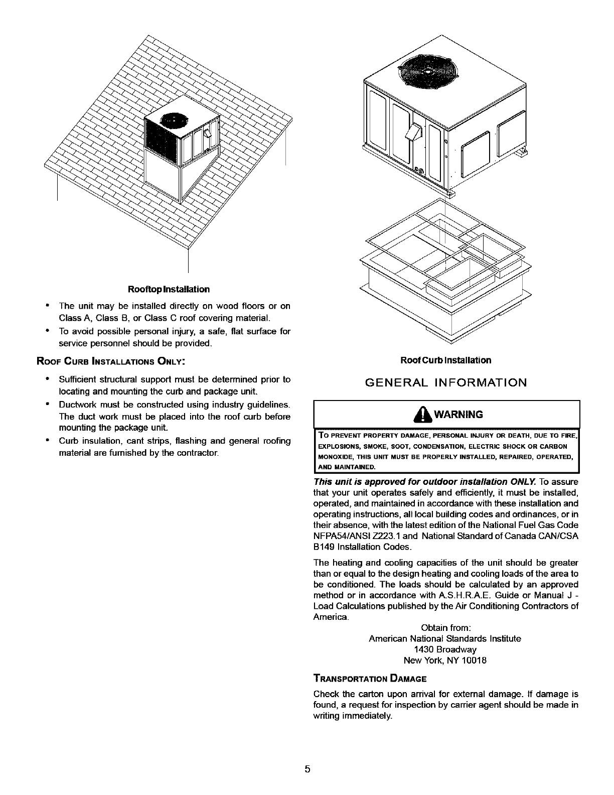
RooRoplns_ll_ion
The unit may be installed directly on wood floors or on
Class A, Class B, or Class C roof covering material.
To avoid possible personal injury, a safe, fiat surface for
service personnel should be provided.
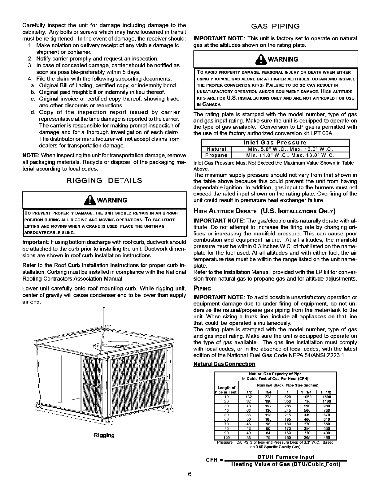
ROOF CURB INSTALLATIONS ONLY:
Sufficient structural support must be determined prior to
locating and mounting the curb and package unit.
Ductwork must be constructed using industry guidelines.
The duct work must be placed into the roof curb before
mounting the package unit.
Curb insulation, cant strips, flashing and general roofing
material are furnished by the contractor.
Roof Curb Installation
GENERAL INFORMATION
_WARNING
To PREVENT PROPERTY DAMAGE, PERSONAL INJURY OR DEATH, DUE TO FIRE
EXPLOSIONS, SMOKE, SOOT, CONDENSATION, ELECTRIC SHOCK OR CARBON
MONOXIDE, THIS UNIT MUST BE PROPERLY INSTALLED, REPAIRED, OPERATED,
AND MAINTAINED.
This unit is approved for outdoor installation ONLY. To assure
that your unit operates safely and efficiently, it must be installed,
operated, and maintained in accordance with these installation and
operating instructions, all local buildingcodes and ordinances, or in
their absence, with the latest edition of the National Fuel Gas Code
NFPA54/ANSI 7323.1 and National Standard of Canada CAN/CSA
B14g Installation Codes.
The heating and cooling capacities of the unit should be greater
than or equal to the design heating and cooling loads of the area to
be conditioned. The loads should be calculated by an approved
method or in accordance with A.S.H.R.A.E. Guide or Manual J -
Load Calculations published by the Air Conditioning Contractors of
America.
Obtain from:
American National Standards Institute
1430 Broadway
New York, NY 10018
TRANSPORTATION DAMAGE
Check the carton upon arrival for external damage. If damage is
found, a request for inspection by carrier agent should be made in
writing immediately.
5
Carefully inspect the unit for damage including damage to the
cabinetry. Any bolts or screws which may have loosened in transit
must be re-tightened. In the event of damage, the receiver should:
1. Make notation on delivery receipt of any visible damage to
shipment or container.
2. Notify carrier promptly and request an inspection.
3. In case of concealed damage, carrier should be notified as
soon as possible-preferably within 5 days.
4. File the claim with the following supporting documents:
a. Original Bill of Lading, certified copy, or indemnify bond.
b. Original paid freight bill or indemnify in lieu thereof.
c. Original invoice or certified copy thereof, showing trade
and other discounts or reductions.
d. Copy of the inspection report issued by carrier
representative at the time damage is reported to the carrier.
The carrier is responsible for making prompt inspection of
damage and for a thorough investigation of each claim.
The distributor or manufacturer will not accept claims from
dealers for transportation damage.
NOTE: When inspecting the unit for transportation damage, remove
all packaging materials. Recycle or dispose of the packaging ma-
terial according to local codes.
RIGGING DETAILS
AWARNING
"O PREVENT PROPERTY DAMAGE, THE UNIT SHOULD REMAIN IN AN UPRIGHT
OSITION DURING ALL RIGGING AND MOVING OPERATIONS. TO FACILITATE
LIFTING AND MOVING WHEN A CRANE IS USED, PLACE THE DN_INAN
_.DEQUATE CABLE SLING.
important: Ifusing bottom discharge with roof curb, ductwork should
be attached to the curb prior to installing the unit. Ductwork dimen-
sions are shown in roof curb installation instructions.
Refer to the Roof Curb Installation Instructions for proper curb in-
stallation. Curbing must be installed in compliance with the National
Rooting Contractors Association Manual.
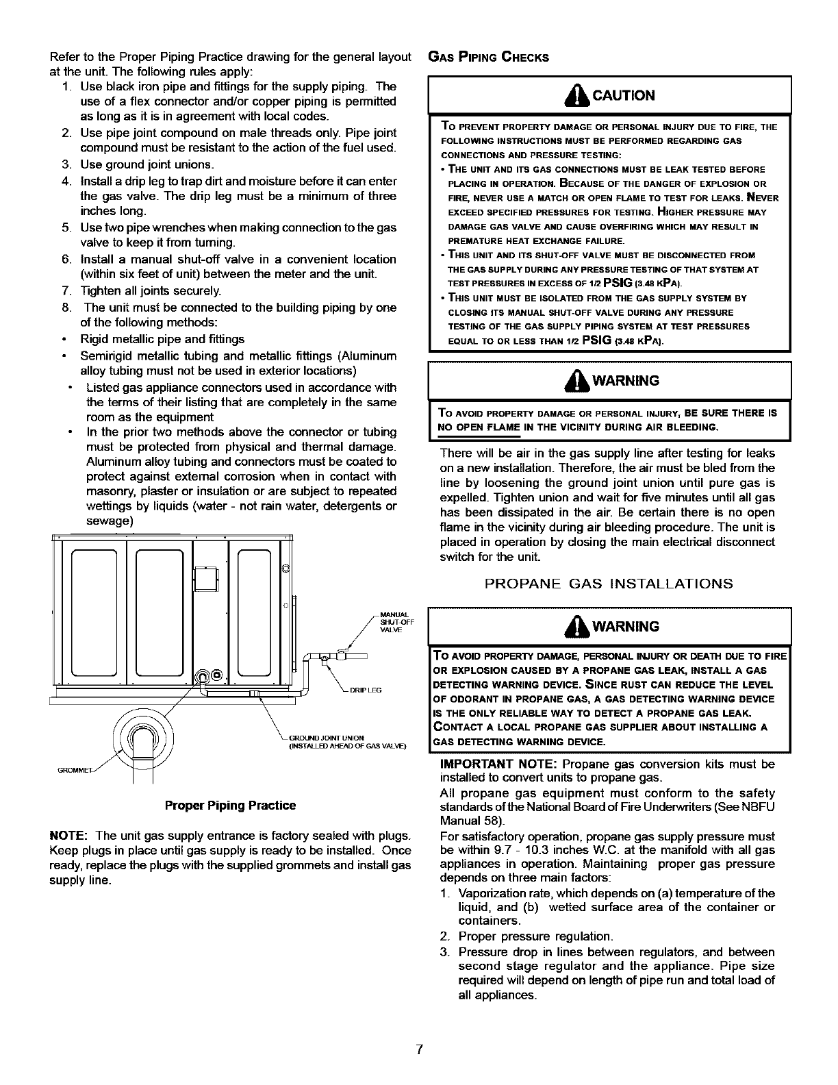
Lower unit carefully onto roof mounting curb. While rigging unit,
center of gravity will cause condenser end to be lower than supply
air end.
Rigging
6
GAS PIPING
IMPORTANT NOTE: This unit is factory set to operate on natural
as at the altitudes shown on the rating plate.
_WARNING
To AVOID PROPER3_f DAMAGE, PERSONAL INJURY OR DEATH WHEN EITHER
USING PROPANE GAS ALONE OR AT HIGHER ALTITUDES, OBTAIN AND INSTALL
THE PROPER CONVERSION KIT(S). FAILURE TO DO SO CAN RESULT IN
UNSATISFACTORY OPERATION AND/OR EQUIPMENT DAMAGE. HIGH ALTITUDE
KITS ARE FOR U.S. INSTALLATIONS ONLY AND ARE NOT APPROVED FOR USE
IN CANADA.
The rating plate is stamped with the model number, type of gas
and gas input rating. Make sure the unit is equipped to operate on
the type of gas available. Conversion to LP gas is permitted with
the use of the factory authorized conversion kit LPT-00A.
Inlet Gas Pressure
Natural I Min. 5.0" W.C., Max. 10.0"W.C.
Propane I Min. 11.0" W.C., Max. 13.0"W.C.
InletGas PressureMust Not Exceedthe MaximumValueShownin Table
Above.
The minimum supply pressure should not vary from that shown in
the table above because this could prevent the unit from having
dependable ignition. In addition, gas input to the burners must not
exceed the rated input shown on the rating plate. Overfiring of the
unit could result in premature heat exchanger failure.
HIGH ALTITUDE DERATE (U.S. INSTALLATIONS ONLY)
IMPORTANT NOTE: The gas/electric units naturally derate with al-
titude. Do not attempt to increase the firing rate by changing ori-
rices or increasing the manifold pressure. This can cause poor
combustion and equipment failure. At all altitudes, the manifold
pressure must be within 0.3 inches W.C. of that listed on the name-
plate for the fuel used. At all altitudes and with either fuel, the air
temperature rise must be within the range listed on the unit name-
plate.
Refer to the Installation Manual provided with the LP kit for conver-
sion from natural gas to propane gas and for altitude adjustments.
PIPING
IMPORTANT NOTE: To avoid possible unsatisfactory operation or
equipment damage due to under firing of equipment, do not un-
dersize the natural/propane gas piping from the meter/tank to the
unit. When sizing a trunk line, include all appliances on that line
that could be operated simultaneously.
The rating plate is stamped with the model number, type of gas
and gas input rating. Make sure the unit is equipped to operate on
the type of gas available. The gas line installation must comply
with local codes, or in the absence of local codes, with the latest
edition of the National Fuel Gas Code NFPA 54/ANSI Z223.1.
Natural Gas Connection
Natural Gas Capacity of Pipe
in Cubic Feet of Gas Per Hour !CFH}
Nominal Black Pipe Size (inches)
Length of
_ipe in Feet 1i2 3/4 1 1 114 1 1/2
10 132 278 520 1050 1600
20 92 190 350 730 1100
30 73 152 285 590 980
40 63 130 245 500 760
50 56 115 215 440 670
60 50 105 195 400 610
70 46 96 180 370 560
80 43 90 170 350 530
90 40 84 160 320 490
100 38 79 150 305 460
Pressure 50 PSIG or less and Pressure Drop of 0 3" WC(Based
on 0 60 Specific Gravrly Gas)
BTUH Furnace input
CFH = Heating Value of Gas (BTUICubic_Foot)
Refer to the Proper Piping Practice drawing for the general layout
at the unit. The following rules apply:
1. Use black iron pipe and fittings for the supply piping. The
use of a flex connector and/or copper piping is permitted
as long as it is in agreement with local codes.
2. Use pipe joint compound on male threads only. Pipe joint
compound must be resistant to the action of the fuel used.
3. Use ground joint unions.
4. Install a drip leg to trap dirt and moisture before itcan enter
the gas valve. The drip leg must be a minimum of three
inches long.
5. Use two pipe wrenches when making connection to the gas
valve to keep it from turning.
6. Install a manual shut-off valve in a convenient location
(within six feet of unit) between the meter and the unit.
7. Tighten all joints securely.
8. The unit must be connected to the building piping by one
of the following methods:
Rigid metallic pipe and fittings
Semirigid metallic tubing and metallic fittings (Aluminum
alloy tubing must not be used in exterior locations)
Listed gas appliance connectors used in accordance with
the terms of their listing that are completely in the same
room as the equipment
In the prior two methods above the connector or tubing
must be protected from physical and thermal damage.
Aluminum alloy tubing and connectors must be coated to
protect against external corrosion when in contact with
masonry, plaster or insulation or are subject to repeated
wettings by liquids (water - not rain water, detergents or
sewage)
Iio
//rl_
_GROUND JOINT UNION
(INSTALl _AHEAD OF GAS VALVE)
MANUAL
/HUT,OFF
VAL_
_DRIP LEG
Proper Piping Practice
NOTE: The unit gas supply entrance is factory sealed with plugs.
Keep plugs in place until gas supply is ready to be installed. Once
ready, replace the plugs with the supplied grommets and installgas
supply line.
GAS PIPING CHECKS
A CAUTION
To PREVENT PROPERTY DAMAGE OR PERSONAL INJURY DUE TO FIRE, THE
FOLLOWING INSTRUCTIONS MUST BE PERFORMED REGARDING GAS
CONNECTIONS AND PRESSURE TESTING:
•THE UNIT AND ITS GAS CONNECTIONS MUST BE LEAK TESTED BEFORE
PLACING IN OPERATION. BECAUSE OF THE DANGER OF EXPLOSION OR
FIRE, NEVER USE A MATCH OR OPEN FLAME TO TEST FOR LEAKS. NEVER
EXCEED SPECIFIED PRESSURES FOR TESTING. HIGHER PRESSURE MAY
DAMAGE GAS VALVE AND CAUSE OVERFIRING WHICH MAY RESULT IN
PREMATURE HEAT EXCHANGE FAILURE.
•THIS UNIT AND ITS SHUT-OFF VALVE MUST BE DISCONNECTED FROM
THE GAS SUPPLY DURING ANY PRESSURE TESTING OF THAT SYSTEM AT
TEST PRESSURES IN EXCESS OF 1/2 PSIG (s.4sKPA).
•THIS UNIT MUST BE ISOLATED FROM THE GAS SUPPLY SYSTEM BY
CLOSING ITS MANUAL SHUT-OFF VALVE DURING ANY PRESSURE
TESTING OF THE GAS SUPPLY PIPING SYSTEM AT TEST PRESSURES
EQUAL TO OR LESS THAN 1/2 PSIG (3_eKPA).
AWARNING
To AVOID PROPERTY DAMAGE OR PERSONAL INJURY_ BE SURE THERE IS
NO OPEN FLAME IN THE VICINITY DURING AIR BLEEDING.
There will be air in the gas supply line after testing for leaks
on a new installation. Therefore, the air must be bled from the
line by loosening the ground joint union until pure gas is
expelled. Tighten union and wait for five minutes until all gas
has been dissipated in the air. Be certain there is no open
flame in the vicinity during air bleeding procedure. The unit is
placed in operation by closing the main electrical disconnect
switch for the unit.
PROPANE GAS INSTALLATIONS
AWARNING
"0 AVOID PROPERTY DAMAGE, PERSONAL INJURY OR DEA'II"I DUE TO FIRE
IR EXPLOSION CAUSED BY A PROPANE GAS LEAK, INSTALL A GAS
DETECTING WARNING DEVICE• SINCE RUST CAN REDUCE THE LEVEL
OF ODORANT IN PROPANE GAS, A GAS DETECTING WARNING DEVICE
IS THE ONLY RELIABLE WAY TO DETECT A PROPANE GAS LEAK.
CONTACT A LOCAL PROPANE GAS SUPPLIER ABOUT INSTALLING A
_AS DETECTING WARNING DEVICE•
IMPORTANT NOTE: Propane gas conversion kits must be
installed to convert units to propane gas.
All propane gas equipment must conform to the safety
standards of the National Board of Fire Underwriters (See NBFU
Manual 58).
For satisfactory operation, propane gas supply pressure must
be within 9.7 - 10.3 inches W.C. at the manifold with all gas
appliances in operation. Maintaining proper gas pressure
depends on three main factors:
1. Vaporization rate, which depends on (a) temperature of the
liquid, and (b) wetted surface area of the container or
containers.
2. Proper pressure regulation.
3. Pressure drop in lines between regulators, and between
second stage regulator and the appliance. Pipe size
required will depend on length of pipe run and total load of
all appliances.
7
TANKS AND PIPING
Complete information regarding tank sizing for vaporization,
recommended regulator settings and pipe sizing is available
from most regulator manufacturers and propane gas suppliers.
Since propane gas will quickly dissolve white lead or most
standard commercial compounds, special pipe dope must be
used. Shellac base compounds resistant to the actions of
liquefied petroleum gases such as Gasolac ®, Stalactic ®,
Clyde's®or John Crane®are satisfactory.
See below for typical propane gas piping.
AWARNING
To PREVENT PROPERTY DAMAGE OR SERIOUS PERSONAL INJURY DUE TO
FIRE OR EXPLOSION CAUSED BY A PROPANE GAS LEAK, INSTALL A GAS
DETECTING WARNING DEVICE.
IF THE PROPANE GAS UNIT IS INSTALLED IN AN EXCAVATED AREA OR A
CONFINED SPACE, A WARNING DEVICE IS REQUIRED DUE TO:
• PROPANE GAS IS HEAVIER THAN AIR AND ANY LEAKING GAS CAN
SETTLE IN ANY LOW AREAS OR CONFINED SPACES.
•PROPANE GAS ODORANT MAY FADE, MAKING THE GAS UNDETECTABLE
EXCEPT WITH A WARNING DEVICE.
FirstStage 5to15 PSlG
Conbnuous
11" W.C.
200 PSlG Second Stage
Maximum
Typical Propane Gas Piping
Sizing Between Nrst and Se(_nd Slage Regulator
MayJmum propane Capacri_s listed are based on 1PSIG pressure Drop at 10
PSIG Set_ng Capacfaes in 1,000 BTU/HR
PiPE OR NOMINAL PIPE SIZE
TUBING TUBING SIZE, O.D., TYPE L SCHEDULE 40
LENGTH,
FEET 3/8" 1/2" 5/8" 3/4" 7/8" 1/2" 3/4"
30 309 700 1,303 2,205 3,394 1,843 3,854
40 265 59_ 1,115 1,887 2,904 1,5(7 3,298
50 235 531 988 1,672 2.574 1,398 2,9"23
60 213 481 896 1,515 2.332 1,267 2,649
70 196 446 824 1,394 2,146 1,165 2,437
80 182 412 767 1,297 1,996 1,084 2,267
90 171 386 719 1,217 1.873 1,017 2,127
100 161 365 679 1,149 1,769 961 2,009
150 130 293 546 923 1,421 /72 1,613
200 111 251 467 790 1,216 660 1,381
250 90 222 414 700 1,078 585 1,224
300 89 201 378 634 976 530 1,109
350 82 185 345 584 898 488 1,020
400 76 172 321 543 836 454 949
To o_nved to Capacit_s at 15 PSIG Se_ngs Multiply by 1 130
To convert to Capacri_s at 5 PSIG SellJngs Mul_ply by 0879
st_ng BetweenSingle or SeOmldStage Regulator and Appliance*
Ma>3mumpropane Capaci_esLISI_I al_ Based on 1/'2,,W C pr_SSUroDropat
11"WC SetUng Capacdl(_inl.OOOBPJ/HR
PiPE OR
TUBING TUBING SIZE, O.D., WPE L
LENGTH,
FEET 3/8" 112" 518" 3/4" 7/8"
10 49 110 205 348 539
20 34 76 141 239 368
30 27 61 114 192 296
40 23 52 97 164 253
50 20 46 86 146 224
60 19 42 Z8 132 20_
80 16 35 67 113 174
1_ 14 32 59 100 154
125 12 28 52 89 137
150 11 26 48 80 124
2c0 10 22 41 69 1_
250 9 19 36 61 94
30(] 8 18 33 55 85
350 7 15 30 51 78
4_ • 15 28 47 73
*DATA IN ACCORDANCE WiTH NFPA PAMPHLET NO 54
NOMINAL PIPE SIZE,
SCHEDULE40
112" 3/4"
291 6G_
200 418
161 336
137 284
122 255
110 231
94 198
84 1•5
74 155
6• 141
58 120
51 10•
46 97
43 89
40 83
1" 1-114" 1-112"
1,146 2,353 3,525
788 1,617 2.423
632 1.299 1.946
541 1,111 1_65
480 985 1,476
436 892 1.337
372 764 1,144
330 677 1,014
2_ 600 899
285 ,544 815
227 465 697
201 412 618
18_ 374
167 344 515
155 320 479
Table 3 -Propane Gas Pipe Sizing
ELECTRICAL WIRING
THERMOSTAT LOCATION
Mount the thermostat approximately five feet above the floor,
in an area that has an inside, vibration-free wall and has good
air circulation.
Movement of air must not be obstructed by furniture, door,
draperies, etc. The thermostat must not be mounted where it
will be affected by drafts, hot or cold water pipes or airducts in
walls, radiant heat from fireplace, lamps, the sun, television,
etc. Consult the Instruction Sheet packaged with thermostat
for mounting instructions.
All unitshave one stage of heating and one stage of mechanical
cooling. Units which will have economizers may use
thermostats with one or two stages of cooling.
*PG 1360 ONLY: These models have two stages of mechanical
cooling. A 1-stage heat, 2-stage cooling thermostat is
recommended for these models.
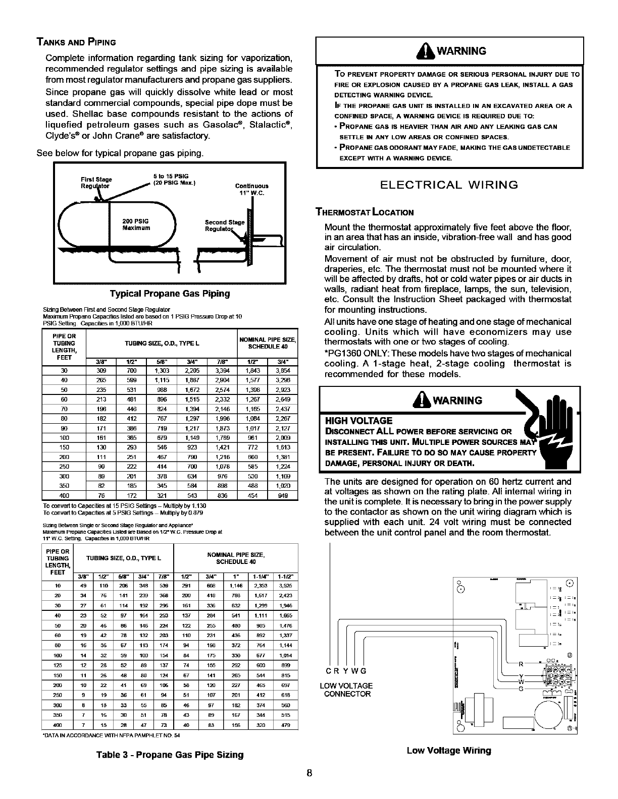
The units are designed for operation on 60 hertz current and
at voltages as shown on the rating plate. All internal wiring in
the unit is complete. It is necessary to bring inthe power supply
to the contactor as shown on the unit wiring diagram which is
supplied with each unit. 24 volt wiring must be connected
between the unit control panel and the room thermostat.
CRYWG
LOW VOLTAGE
CONNECTOR
o
Q ,=,_ Q
It ....
@
Low Voltage Wiring
8
Y_2C RYIWG
LOW VOLTAGE
CONNECTOR
"Note:Junction box location
shown is optional and is
for illustration purposes only.
JUNCTION BOX
Electrical Power Directly To Junction Box
Low Voltage Wiring-*PG1360 Only
Refer to the unit wiring diagram for electrical connections.
When installed, the unit must be electrically grounded in
accordance with local codes or in the absence of local codes,
with the National Electrical Code, ANSI/NFPA No. 70, and/or
the CSA C22.1 Electrical Code. Ensure low voltage
connections are waterproof.
_'_ WARNING I
TO AVOID THE RISK OF ELECTRICAL SHOCK_ WIRING TO THE UNIT
MUST BE PROPERLY GROUNDED.
i_ CAUTION
To AVOID PROPERTY DAMAGE OR PERSONAL INJURY DUE TO FIRE, USE
ONLY COPPER CONDUCTORS.
i_ CAUTION
O PREVENT IMPROPER AND DANGEROUS OPERATION DUE TOWIRING ERRORS
_,BEL ALL WIRES PRIOR TO DISCONNECTION WHEN SERVICING CONTROLS.
_/ERIFY PROPER OPERATION AFTER SERVICING.
For unit protection, use a fuse or HACR circuit breaker that is
in excess of the circuit ampacity, but less than or equal to the
maximum overcurrent protection device. DO NOT EXCEED
THE MAXIMUM OVERCURRENT DEVICE SIZE SHOWN ON
UNIT DATA PLATE.
All line voltage connections must be made through
weatherproof fittings. All exterior power supply and ground
wiring must be in approved weatherproof conduit. Low voltage
wiring from the unit control panel to the thermostat requires
coded cable. See below for ground level and rooftop wiring.
Electrical Power Routed Through Bottom of Unit
Typical Electrical Wiring Unit Voltage
UNITVOLTAGE
The unit transformer is factory connected for 230V operation.
If the unit is to operate on 208'4, reconnect the transformer
primary lead as shown on the unit wiring diagram. The induced
draft blower on some models is equipped with a 230V lead
(red) and a 208V lead (black). If equipped, connect the induced
draft blower 208V lead (black) in place of the 230V lead (red).
Tape the unused 230V lead.
HEAT ANTICIPATOR SETTING
The heat anticipator is to be set by measuring the load
(amperage) atthe "R" circuit. Followthe instructions provided
by the thermostat for more details.
Typical Thermostat and Unit 24 V Wiring Hookup
9
Typical 2-Stage Cool Thermostat and
Unit 24 V Wiring Hookup
*PC1360 Only
CIRCULATING AIR AND FILTERS
AIRFLOW CONVERSION
Units can easily be converted from horizontal to down-
discharge airflow delivery. In down-discharge or high static
installations, the installer should measure the total external
static and review the blower performance charts before
performing the installation, in some installations it will be
necessary to change the blower speed to provide proper air
flow.
Horizontal Air Flow
Remove supply and return duct covers which are attached to
the unit as shown below.
Removethesecovers
forhorizonta_duct
applicaf_ons
Down Discharae AoDlications
Cut insulation around bottom openings and remove panels
from the bottom of the unit, saving the screws holding the
panels in place.
DUCTWORK
Duct systems and register sizes must be properly designed
for the C.F.M. and external static pressure rating of the unit.
Ductwork should be designed in accordance with the
recommended methods of Air Conditioning Contractors of
America Manual D (Residential) or Manual Q (Commercial).
All ductwork exposed to the outdoors must include a
weatherproof barrier and adequate insulation.
Aduct system should be installed in accordance with Standards
of the National Board of Fire Underwriters for the Installation
of Air Conditioning, Warm Air Heating and Ventilating Systems.
Pamphlets No. 90A and 90B.
The supply duct from the unit through a wall may be installed
without clearance. However, minimum unit clearances as
shown in the appendix must be maintained. The supply duct
should be provided with an access panel large enough to
inspect the air chamber downstream of the heat exchanger. A
cover should be tightly attached to prevent air leaks.
For duct flange dimensions on the unit refer to the Unit
Dimension illustration in the appendix.
For down-discharge applications, the ductwork should be
attached to the roof curb prior to installing the unit. Ductwork
dimensions are shown in the roof curb installation manual.
If desired, supply and return duct connections to the unit may
be made with flexible connections to reduce possible unit
operating sound transmission.
FILTERS
_k, CAUTION
To PREVENT PROPERTY DAMAGE DUE TO FIRE AND LOSS OF
EQUIPMENT EFFICIENCY OR EQUIPMENT DAMAGE DUETODDSTANDLINT
BUILD UP ON INTERNAL PARTS, NEVER OPERATE UNIT WITHOUT AN AIR
FILTER INSTALLED IN THE RETURN AIR SYSTEM.
Even though a return air filter is not supplied with this unit,
there must be a means of filtering all return air. The *PG1248,
*PG1260, *PG1342, *PG1348, and *PG136g models are
provided with internal filter racks for down-discharge
applications. All units may be externally filtered.
Refer to the unit filter size chart in the appendix for filter size
information.
Filters installed external to the unit should be sized in
accordance with their manufacturer recommendations. A
throwaway filter must be sized for a maximum face velocity of
300 feet per minute.
Filter Installation
Important: When installing a filter, the air flow arrows on the
filter must point toward the circulator blower.
VENTING
Remove these panels
for downflow duct
applications
Duct Cover Installation
NOTE: Venting is self-contained. Do not modify or block.
FLUE HOOD INSTALLATION
Install the flue hood and bug screen prior to operation of the
unit.
10
Toinstallthefluehoodcoverandbugscreen:
1. Removethefluehoodandbugscreenfrominsidethe
heatexchangercompartment.
2. Slide the bug screen over the flanges of the flue hood and
attach the flue hood and screen to the unit with the sheet
metal screws provided.
Flue Hood and Bug Screen Installation
CONDENSATE DRAIN
CONDENSATE DRAIN CONNECTION
A3/4" NPT drain connection is supplied for condensate piping. An
external trap must be installed for proper condensate drainage.
DRAIN
coNNECTION
2"M,.,MoM/,I/
TUBING-HOSE _ _'/_ 3" MiNiMUM
OR PIPE _q_
_PA POSITIVE LIQUID
SEAL IS REQUIRED
Drain Connection
NORMAL SEQUENCES OF OPERATION
HEATING
This unit is equipped with an ignitioncontrol that automatically
lights the main burner. DO NOT attempt to light the main
burners by any other method.
1. Thermostat calls for heat. The induced draft blower
energizes for a 15-second pre-purge.
2. The spark igniter and gas valve energizes for 7seconds.
NOTE: The igniter produces a very intense electrical spark
that ignites the gas.
3. The 30-second HEAT FAN ON delay time begins.
*PG1348,60 ONLY: Heat on delay begins when thermostat
calls for heat. ECM motor is energized approximately 45
seconds later. NOTE: ECM motor may operate at
approximately 100 CFM or less during the 45 second on
delay period. ECM motor will energize at heating speed
4.
5.
6.
after the 45 second delay regardless of the status of the
main burner flame.
The unit delivers heat to the conditioned space until the
thermostat is satisfied.
The gas valve deenergizes. The induced draft blower
continues operation for a 29-second post-purge.
Ignition control begins timing the HEAT FAN OFF delay.
There is an adjustable HEAT FAN OFF delay of
approximately 12011351150 seconds (factory set at 150).
After the HEAT FAN OFF delay time has elapsed, the blower
will deenergize. This allows any additional heat in the heat
exchanger to be transferred to the conditioned space.
*PG1348,60 ONLY: HEAT FAN OFF delay is fixed at 180
seconds. Airflow level is 50% of nominal heating airflow.
COOLING
1. Thermostat calls forcooling. The compressor and outdoor
fan are energized.
2. Approximately seven seconds later, the indoor fan starts.
3. The unit will deliver cooling to the conditioned space until
the thermostat is satisfied.
4. The compressor and outdoor fan will be deenergized when
the thermostat opens.
5. The indoor fan continues to run for approximately 60
seconds after the thermostat is satisfied. This allows
additional cooling from the indoor coil to be transferred to
the conditioned space. Then, the indoor fan stops.
*PG1348 ONLY:
1. Thermostat calls for cooling. Outdoor fan and compressor
are energized. ECM motor is energized almost immediately
for 30 seconds at 50% of the nominal airflow. Airflow
then increases to nominal airflow.
2. The unit will deliver cooling to the conditioned space until
thermostat is statisfied.
3. The outdoor fan and compressor will be de-energized when
thermostat opens.
4. ECM motor continues to operate for approximately 60
seconds at 50% of nominal airflow after thermostat opens.
*PG1360 ONLY:
1. Thermostat calls for low stage cooling. Outdoor fan and
low stage compressor are energized. ECM motor is
energized almost immediately for 30 seconds at 50% of
the nominal low stage airflow. Airflow then increases to
nominal low stage airflow.
If thermostat calls for high stage cooling, outdoor fan and
low and high stage compressor is energized. ECM motor is
energized almost immediately for 30 seconds at 50% of
the nominal high stage airflow. Airflow then increases to
nominal high stage airflow.
2. The unit will deliver cooling to the conditioned space until
thermostat is satisfied.
3. The outdoor fan and low stage compressor (or low and high
stage compressor) will be de-energized when thermostat
opens.
4. ECM motor continues to operate for approximately 60
seconds at 50% of nominal low stage airflow (or high stage
airflow if thermostat call was for high stage cooling) after
thermostat opens.
NOTE: A180-second anti-short cycle is integral to the control and
prevents recycling of the compressor.
FAN ONLY
1. Thermostat calls for FAN ONLY by energizing "G".
2. Approximately seven seconds later, the indoor fan starts.
11
3. The indoor fan continues to run for approximately 60
seconds after "G" is deenergized.
*PG1348,60 ONLY:
1. Thermostat calls for FAN ONLY by energizing "G".
2. ECM motor is energized almost immediately at
approximately 30% of the nominal high stage cooling
airflow, depending on setting (see "Blower Speed
Adjustment" section).
3. ECM is de-energized almost immediately after "G" is de-
energized.
STARTUP, ADJUSTMENTS, AND CHECKS
HEATING STARTUP
This unit is equipped with an electronic ignition device to
automatically light the main burners. It also has a power vent
blower to exhaust combustion products.
On new installations, or if a major component has been
replaced, the operation of the unit must be checked.
Check unit operation as outlined in the following instructions.
If any sparking, odors, or unusual sounds are encountered,
shut off electrical power and recheck for wiring errors, or
obstructions in or near the blower motors. Duct covers must
be removed before operating unit.
Heat Anticioator Settino
Set the heat anticipator on the room thermostat to 0.4 amps to
obtain the proper number of heating cycles per hour and to
prevent the room temperature from overshooting the room
thermostat setting.
Rollout Protection Control
The rollout protection device opens, cutting power to the gas
valve, if the flames from the burners are not properly drawn
into the heat exchanger. The rollout protection device is located
on the burner bracket. The reason for elevated temperatures
at the control should be determined and repaired prior to
resetting this manual reset control.
,_ WARNING
To AVOID PROPERTY DAMAGE, PERSONAL INJURY OR DEATH DUE TO FIRE
OR EXPLOSION, A QUALIFIED SERVICER MUST INVESTIGATE THE REASON FOR
THE ROLLOMT PROTECTION DEVICE TO OPEN BEFORE MANUALLY RESETrlNG
THE ROLLOUT PROTECTION DEVICE.
._ _ FRolIout Protection
Rollout Protection on Burner Bracket
Secondary Limit Control
The secondary limit control is located on the top of the blower
scroll assembly. This control opens when elevated
temperatures are sensed. Elevated temperatures at the
control are normally caused by blower failure. The reason for
the opening should be determined and repaired prior to
resetting.
If the power to the unit is interrupted during the heating cycle, it
may cause the secondary limit to trip. Once the blower
compartment temperature drops below the limitreset temperature,
the limit will automatically reset.
Secondary Limit Control
Pre-O_eration Checks
1. Close the manual gas valve external to the unit.
2. Turn off the electrical power supply to the unit.
3. Set the room thermostat to its lowest possible setting.
4. Remove the heat exchanger door on the side of the unit by
removing screws.
5. This unit is equipped with an ignition device which
automatically lightsthe main burner. DO NOTtry to light burner
by any other method.
6. Move the gas control valve switch to the OFF position. Do not
force.
7. Wait five minutes to clear out any gas.
8. Smell for gas, including near the ground. This is important
because some types of gas are heavier than air. If you have
waited five minutes and you do smell gas, immediately follow
the warnings on page 3 of this manual. If having waited for
five minutes and no gas smell is noted, move the gas control
valve switch to the ON position.
9. Replace the heat exchanger door on the side of the unit.
10. Open the manual gas valve external to the unit.
11. Turn on the electrical power supply to the unit.
12. Set the thermostat to desired setting.
Gas Valve • _L_
4
Switch
I I_ OUTLET
@
White-Rodgers Model 36F22
_Gas Valve
On]Off
Selector
Switch
White-Rodgers 36G22
12
Gas SuDolvAnd Manifold Check
Gas supply pressure and manifold pressure with the burners
operating must be as specified on the rating plate.
Gas Inlet Pressure Check
Gas inlet pressure must be checked and adjusted in
accordance to the type of fuel being consumed.
With Power And Gas Off:
1. Connect a water manometer or adequate gauge to the inlet
pressure tap of the gas valve.
inlet gas pressure can also be measured by removing the
cap from the dripleg and installing a predrilled cap with a
hose fitting.
With Power And Gas On:
2. Put unit into heating cycle and turn on all other gas
consuming appliances.
Natural Inlet Gas Pressure I
Min. 5.0"W.C., Max. 10.0" W.C. IPropane Min. 11.0" W.C., Max. 13.0" W.C.
NOTE: Inlet Gas Pressure Must Not Exceed the Maximum Value
Shown.
If operating pressures differ from above, make necessary
pressure regulator adjustments, check piping size, etc., and/
or consult with local utility.
TOParna=e
M
Mar_aeter
Measuring inlet Gas Pressure
Alternate Method
Manifold Pressure Check
The gas valve has a tapped opening to facilitate measurement
of the manifold pressure. A =U" Tube manometer having a
scale range from 0 to 12 inches of water should be used for
this measurement. The manifold pressure must be measured
with the burners operating.
Toadjust the pressure regulator, remove the adjustment screw
or cover on the gas valve. Turn out (counterclockwise) to
decrease pressure, turn in (clockwise) to increase pressure.
Only small variations in gas flow should be made by means
of the pressure regulator adjustment. In no case should the
final manifold pressure vary more than plus or minus 0.3
inches water column from the specified nominal pressure.
Any major changes in flow should be made by changing the
size of the burner orifices. The measured input rate to the
furnace must not exceed the rating specified on the unit rating
plate.
For natural gas, the manifold pressure must be between 3.2
and 3.8 inches water column (3.5 nominal).
For propane gas, the manifold pressure must be between
9.7 and 10.3 inches water column (10.0 nominal).
13
Gas InDut/Natural Gas OnM Check
To measure the gas input use a gas meter and proceed as
follows:
1. Turn off gas supply to all other appliances except the unit.
2. With the unit operating, time the smallest dial on the meter
for one complete revolution. If this is a 2 cubic foot dial,
divide the seconds by 2; if it is a1 cubic foot dial, use the
seconds as is. This gives the seconds per cubic foot of gas
being delivered to the unit.
3. INPUT=GAS HTG VALUE x 3600 /SEC. PER CUBIC FOOT
Example: Natural gas with a heating value of 1000 BTU per cubic
foot and 34 seconds per cubic foot as determined by Step 2, then:
Input =1000 x 3600 /34 = 106,000 BTU per Hour. NOTE:
BTU content of the gas should be obtained from the gas
supplier. This measured input must not be greater than
shown on the unit rating plate.
4. Relight all other appliances turned off in step 1. Be sure all
pilot burners are operating.
Main Burner Flame Check
Flames should be stable, soff and blue (dust may cause orange
tips but they mustnot be yellow) and extending directly outward
from the burner without curling, floating or liffingoff.
Temoereture Rise Check
Check the temperature rise through the unit by placing
thermometers in supply and return air registers as close to the
unit as possible. Thermometers must not be able to sample
temperature directly from the unit heat exchangers, or false
readings could be obtained.
1. All registers must be open; all duct dampers must be in their
final (fully or partially open) position and the unit operated
for 15 minutes before taking readings.
2. The temperature dse must be within the range specified on
the rating plate.
NOTE: Air temperature rise is the temperature difference between
supply and return air.
With a properly designed system, the proper amount of
temperature rise will normally be obtained when the unit is
operated at rated input with the recommended blower speed.
If the correct amount of temperature rise is not obtained, it
may be necessary to change the blower speed. Ahigher blower
speed will lower the temperature rise. Aslower blower speed
will increase the temperature rise.
NOTE: Blower speed MUST be set to give the correct air tempera-
ture rise through the unit as marked on the rating plate.
External Static Pressure Check
The total external static pressure must be checked on this unit
to determine ifthe airflow is proper.
Blower Soeed Adjustments
I _WARNING
TO AVOID PERSONAL INJURY OR DEATH DUE TO ELECTRIC SHOCK, REMOVE
ROMT.EU...OE OREC.ANO,.OSPEEOTAPSONTHE
Refer to the wiring diagram in the appendix to verify speed tap
settings.
Blower speeds are to be changed at the ignitioncontrol board.
Both heat speed and cool speed terminals are supplied on the
board along with two unused motor lead terminals.
*PG1348 and *PG1360 models are equipped with GE ECM
motors. These motors offer greater airflow flexibility as well
as dehumidification. The airflow delivery for these models
canbeadjustedbychanging the position of clip switches on
a low voltage terminal board. The figure below shows the
dipswitch layout on the low voltage terminal board as well as
the function of each set of switches. The "HEAT" function
(switches 1 and 2) provides airflow adjustment for heating
airflow. The _COOL" adjustment function (switches 5 and 6)
provides airflow adjustments for cooling airflow. The
"ADJUST' function (switches 7 and 8) will adjust the heating
AND cooling airflow +10% or -15%. The "DELAY" function
(switches 3 and 4) is not field adjustable.
HEAT DELAY COOL /_JUST
lo....,.,,
To adjust the HEAT, COOL or ADJUST functions, simply change
the ON/OFF position of the appropriate dipswitches. The table
below shows the ON/OFF combinations for the various switches
and the corresponding A, B, C, or D taps. Refer to the Product
Data Book applicable to your model for airflow tables and
temperature rise. The =Dipswitch Position" table below shows the
factory dipswitch settings for each model. The =CFM" table below
shows the nominal heating and cooling CFM for each model.
HEAT COOL ADJUST
Factc_, Set. not field adjustable
•Tap D has no effect on airflow
Dipswitch Settings and Corresponding Tap
Dehumidification
The GE ECM motor has the capability to provide increased
dehumidification during cooling operation. This is
accomplished by lowering the airflow to approximately 85%
of the nominal cooling airflow. Example: Unit is operating at
1400 CFM and humidistat calls for dehumidification. Resulting
airflow is 0.85" 1400 CFM = 1190 CFM.
To make use of this feature, a 24VAC humidistat which
opens on humidity rise is required. Connect humidistat to
the HUMIDISTAT/HUM terminal on the low voltage terminal
board (see wiring diagram in the appendix). Clip the BUM/
PJ6 jumper on the low voltage terminal board. The system
is now ready to provide dehumidification.
Limit Check
Check limit control operation alter 15 minutes of operation by
blocking the return air grille(s).
1. Alter several minutes the main burners must go OFF.
Blower will continue to run.
2. Remove air restrictions and main burners will relight after
a cool down period of a few minutes.
Adjust the thermostat setting below room temperature.
1. Main burners must go OFF.
2. Circulating Air Blower will continue to run for 120, 135 or
150 seconds, depending on the setting.
*PG1348,60 ONLY: Circulating Air Blower will continue to run
for 180 seconds.
DIP SWITCH POSITION
Model 12 3 4 5 678
GPG13480701* ON ON OFF OFF ON OFF OFF OFF
GPG13480901* OFF ON OFF OFF ON OFF OFF OFF
GPG13481151* ON OFF OFF OFF ON OFF OFF OFF
GPG13600901* ON ON OFF OFF OFF OFF OFF OFF
GPG13601151* OFF ON OFF OFF OFF OFF OFF OFF
GPG13601401* ON OFF OFF OFF OFF OFF OFF OFF
CFM
Model HEAT COOL
GPG13480701* 1020 1540
GPG13480901* 1140 1540
GPG13481151* 1420 1540
GPG13600901* 1140 1810
GPG13601151* 1420 1810
GPG13601401* 1700 1810
Unit dipswitches are factory set for each model, see label on
blower housing for CFM adjustment next to low voltage terminal
connections.
NOTE: Heating airflow must be adjusted to provide the tempera-
ture rise shown on rating plate.
*PG1360 ONLY: Low stage airflow is approximately 75% of
high stage cooling airflow. Example: High stage cooling airflow
is 1800 CFM. Low stage cooling airflow is 0.75"1800 CFM =
1350 CFM.
The adjustment factors for the ADJUST function are A = 1, B =
1.10 (+10%) and C = 0.85 (-15%). The D tap for the ADJUST
function has no effect on airflow. Example: Airflow tables
indicate 1425 CFM. With the ADJUST set to B tap, the CFM
becomes 1.10"1425 CFM = 1568 CFM.
Control Board (Top)
NOTE: If necessary, adjust fan OFF delay settings to obtain satis-
factory comfort level.
_WARNING
THIS UNIT MUST NOT BE USED AS A "CONSTRUCTION HEATER" DURIN_I THE
FINISHIN_I PHASES OF CONSTRUCTION ON A NEW STRUCTURE. THIS TYPE OF
USE MAY RESULT IN PREMATURE FAILURE OF THE UNiT DUE TO EXTREMELY
LOW RETURN AIR TERMPERATURES AND EXPOSURE TO CORROSIVE OR VERY
DIRTY ATMOSPHERES.
Unit Shutdown
1. Set the thermostat to lowest setting.
2. Turn off the electrical power supply to the unit.
3. Remove the heat exchanger door on the side of the unit by
removing screws.
4. Move the gas control valve switch to the OFF position. Do
not force.
5. Close manual gas shutoff valve external to the unit.
6. Replace the heat exchanger dcor on the unit.
7. if cooling and/or air circulation will be desired, turn ON the
electrical power.
14
COOLING STARTUP
NOTE: Check all manual reset limit controls in heating circuit if
cooling mode does not operate.
ComDressor Protection Devices
The compressor includes components which are designed
to protect the compressor against abnormal operating
conditions.
_WARNING
To PREVENT PERSONAL INJURY OR DEATH, ALWAYS DISCONNECT ELECTRICAl
POWER BEFORE INSPEC_NG OR SERVICING THE UNIT. ALL COMPRESSOR
PROTECTION DEVICES RESET AUTOMATICALLY, ENERGIZJNG THE CONTACTOR
AND OUTDOOR FAN.
Coolinn Refrigerant Charoino
Check unit charge before putting the cooling section into full
operation. The unit is factory charged with R-22 for nominal air
flow and static pressure conditions. The unit has a piston
flowrator expansion device.
NOTE: *PG1360 is equipped with a thermostatic valve expansion
device.
To ensure the unit is properly charged for the intended
application, check the unit refrigerant superheat at the
compressor. The refrigerant superheat is a function of outdoor
ambient temperature and return air temperature of the
conditioned space. It is the installing contractors responsibility
to ensure the proper refrigerant superheat at the compressor
is adjusted for each application. For example, 10 degree
refrigerant superheat level is adequate fora 95 degree outdoor
ambient temperature and a 78 - 80 degree for indoor return air
temperature. As the outdoor ambient temperature rises the
superheat decreases and as the outdoor ambient temperature
lowers the superheat increases. Proper superheat adjustment
optimizes cooling performance.
For models equipped withthermostatic expansion valve, charge
system to 12-14 degrees of subcooling, adjust expansion valve
stem for superheat setting when necessary.
NOTE: The expansion valve will not need adjustment for most
applications. Ensure system superheat is set between 10-12 degrees
after final adjustment.
Coolina Operation
NOTE: Mechanical cooling cannot be reliably provided at ambient
temperatures below 50 ° F.
1. Turn on the electrical power supply to the unit.
2. Place the room thermostat selector switch in the COOL
position(or AUTO ifavailable, and ifautomatic changeover
from cooling to heating is desired).
3. Set the room thermostat to the desired temperature.
TROUBLESHOOTING
IGNITION CONTROL ERROR CODES
The following presents probable causes of questionable unit
operation. Refer to Diagnostic Indicator Chart for an
interpretation of the signal and to thissection for an explanation.
Remove the control box access panel and note the number of
diagnostic LED flashes. Refer to Diagnostic Indicator Chart
for an interpretation of the signal and to this section for an
explanation.
ABNORMAL OPERATION -HEATING
Internal Control Failure
If the integrated ignition control in this unit encounters an
internal fault, it will go into a =hard" lockout and turn off the
diagnostic LED. If diagnostic LED indicates an internal fault,
check power supply to unit for proper voltage, check all fuses,
circuit breakers and wiring. Disconnect electric power for five
seconds. If LED remains off after restoring power, replace
control.
Extemal Lockout
An external lockout occurs if the integrated ignition control
determines that a measurable combustion cannot be
established within three (3) consecutive ignition attempts. If
flame is not established within the seven (7) second trial for
ignition, the gas valve is deenergized, 15 second inter-purge
cycle is completed, and ignition is reattempted. The control
will repeat this routine three times if a measurable combustion
is not established. The control will then shut off the induced
draft blower and go into alockout state.
If flame is established but lost, the control will energize the
circulatorblower at the heat speed and then begin a new ignition
sequence. If flame is established then lost on subsequent
attempts, the control will recycle for four (4) consecutive ignition
attempts (five attempts total) before locking out.
The diagnostic fault code is 1 flash for a lockout due to failed
ignitionattempts or flame dropouts. The integrated control will
automatically reset after one hour,or itcan be reset by removing
the thermostat signal or disconnecting the electrical power
supply for over five seconds. If the diagnostic LED indicates
an external lockout, perform the following checks:
Check the supply and manifold pressures
Check the gas orifices for debris
Check gas valve for proper operation
Check secondary limit
A dirty filter, excessive duct static, insufficient air flow, a
faulty limit, or afailed circulator blower can cause this
limit to open. Check filters, total external duct static,
circulator blower motor, blower motor speed tap (see
wiring diagram), and limit. An interruption in electrical
power during a heating cycle may also cause the
auxiliary limit to open. The automatic reset secondary
limit is located on top of the circulator blower assembly.
Check rollout limit
If the burner flames are not properly drawn into the heat
exchanger, the flame rollout protection device willopen.
Possible causes are restricted or blocked flue passages,
blocked or cracked heat exchanger, a failed induced
draft blower, or insufficient combustion air. The rollout
protection device is amanual reset limit located on the
burner bracket. The cause of the flame rollout must be
determined and corrected before resetting the limit.
Check flame sensor
A drop in flame signal can be caused by nearly invisible
coating on the sensor. Remove the sensor and carefully
clean with steel wool.
Check wiring
Check wiring for opens/shorts and miswirieg.
Important: If you have to frequently reset your gaslelectric
package unit, it means that a problem exists that should
be corrected. Contact aqualified servicer for further
information.
15
Pressure Switch Stuck ODen
A pressure switch stuck open can be caused by a faulty
pressure switch, faulty wiring, a disconnected or damaged
hose, a blocked or restricted flue, or a faulty induced draft
blower.
If the control senses an open pressure switch during the pre-
purge cycle, the induced draft blower only will be energized. If
the pressure switch opens after ignition has begun the gas
valve is deenergized, the circulator blower heat off cycle begins,
and the induced draft blower remains on. The diagnostic fault
code is two flashes.
Pressure Switch Stuck Closed
A stuck closed pressure switch can be caused by a faulty
pressure switch or faulty wiring, if the control encounters a
pressure switch stuck closed, the induced draft blower remains
off. The diagnostic LED code for this fault is three (3) flashes.
ODen Thermal Protection Device
Ifthe primary limit switch opens, the gas valve is immediately
deenergized, the induced draft and air circulating blowers are
energized. The induced draft and air circulator blowers remain
energized untilthe limit switch recloses. The diagnostic fault
code for an open limit is four (4) flashes.
A primary limit will open due to excessive supply air
temperatures. This can be caused by a dirty filter, excessive
duct static, insufficient air flow, or a faulty limit. Check filters,
total external duct static, blower motor, blower motor speed
tap (see wiring diagram), and limit. This limit will automatically
reset once the temperature falls below a preset level.
Flame Detected with Gas Valve Closed
If flame is detected with the gas valve deenergized, the
combustion and air circulator blowers are energized. The
diagnostic fault code is five (5) flashes for this condition. The
control can be reset by removing the power supply to the unit
or it will automatically reset after one hour. Miswiring is the
probable cause for this fault.
ABNORMAL OPERA TION - COOLING
Short Cycle Compressor Delay
The automatic ignition controlhas a built-infeature that prevents
damage to the compressor in short cycling situations. In the
event of intermittent power losses or intermittent thermostat
operation, the ignition control will delay output to the
compressor contactor for three minutes from the time power is
restored. (Compressor is off atotal of three minutes). The
diagnostic LED will flash six (6) times to indicate the
compressor contactor output is being delayed.
Have the gas heating section of the unit checked at least
once a year before the heating season begins, to be sure that
the combustion air inlet and flue outlet hoods are not blocked
by debris, which would prevent adequate combustion air and
a properly operating vent system.
FILTER REPLACEMENT OR CLEANING
A return air filter is not supplied with this unit; however, there
must be a means of filtering all of the return air. The filter(s)
may be located in the return air duct(s), or return air filter grifie(s).
Consult with your installing dealer for the actual location of the
return air filter(s) for your unit.
Dirty filters are the most common cause of inadequate heating
or cooling performance. Filter inspection should be made at
least every two months; more often if necessary because of
local conditions and usage.
Dirty throwaway filters should be discarded and replaced with
a new, clean filter. Dirty permanent filters should be washed
with water, thoroughly dried and sprayed with a filter adhesive
before being reinstalled. (Filter adhesives may be found at many
hardware stores.) Permanent filters should last several years.
However, should one become torn or uncleanable, it should
be replaced.
CABINET FINISH MAINTENANCE
Use a fine grade automotive wax on the cabinet finish to
maintain the finish's original high luster. This is especially
important in installations with extended periods of direct
sunlight.
CLEAN OUTSIDE COIL (QUALIFIED SERVICER ONLY)
The coil with the outside air flowing over it should be inspected
annually and cleaned as frequently as necessary to keep the
finned areas free of lint, hair and debris.
CONDENSER_ EVAPORATOR_AND INDUCED DRAFT MOTORS
Bearings on the air circulating blower motor, condenser motor
and the combustion fan motor are permanently lubricated. No
additional oiling is required.
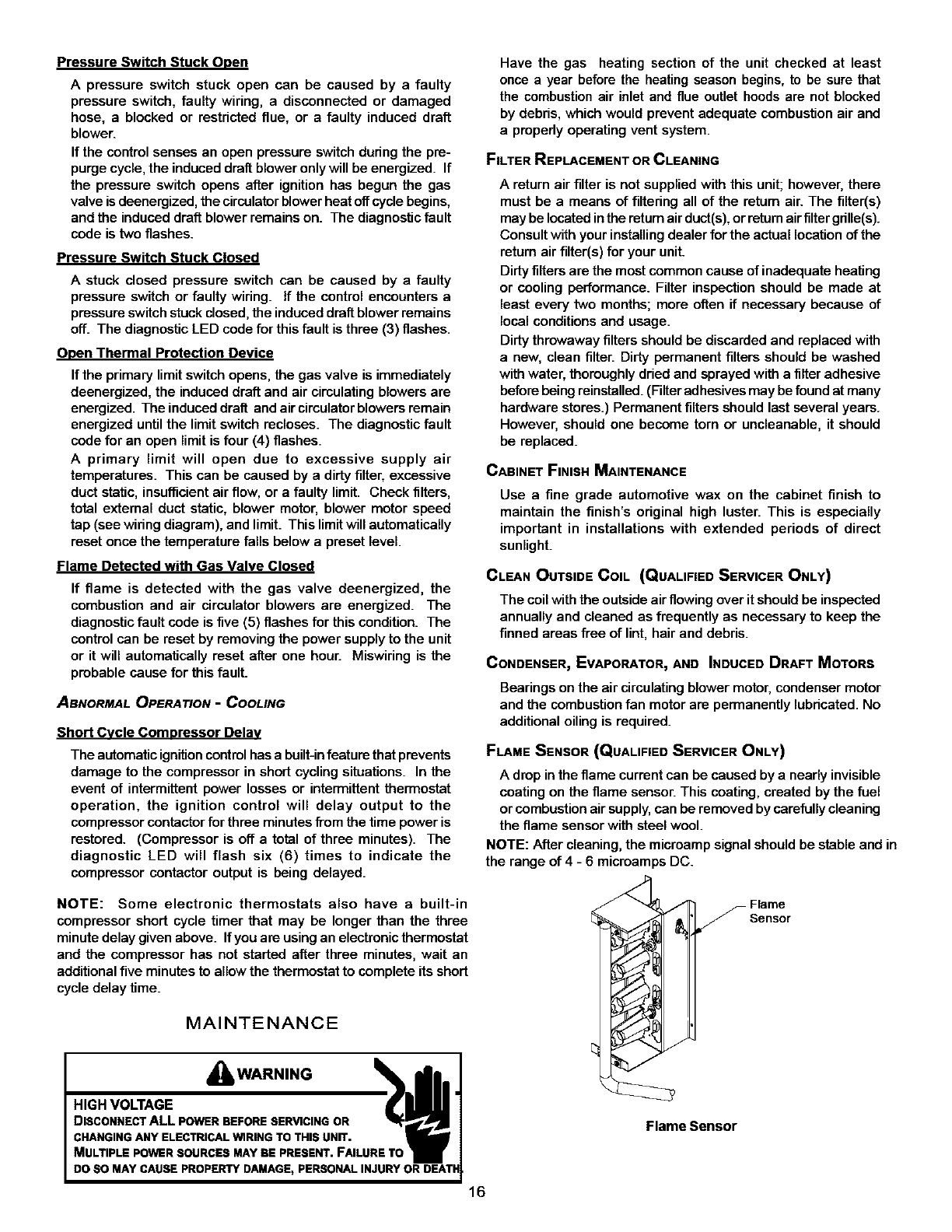
FLAME SENSOR (QUALIFIED SERVICER ONLY)
Adrop in the flame current can be caused by a nearly invisible
coating on the flame sensor. This coating, created by the fuel
or combustion airsupply, can be removed by carefully cleaning
the flame sensor with steel wool.
NOTE: After cleaning, the microamp signal should be stable and in
the range of 4 - 6 microamps DC.
NOTE: Some electronic thermostats also have a built-in
compressor short cycle timer that may be longer than the three
minute delay given above. Ifyou are using an electronic thermostat
and the compressor has not started after three minutes, wait an
additional five minutes to allow the thermostat to complete its short
cycle delay time.
MAINTENANCE
I..o.vo. .o0-w-"'"°
DISCONNECTALL POWERBEFORESERVICINGOR
16
!/Flame
_ _Sensor
J
Flame Sensor
FLUEPASSAGES(QUALIFIEDSERVICERONLY)
Atthestart of each heating season, inspect and, ifnecessary,
clean the unit flue passage.
CLEANING FLUE PASSAGES (QUALIFIED SERVICER ONLY)
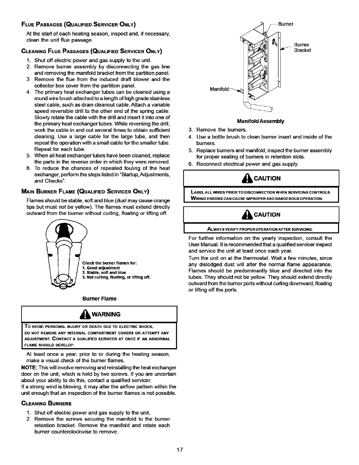
1. Shut off electric power and gas supply to the unit.
2. Remove burner assembly by disconnecting the gas line
and removing the manifold bracket from the partition panel.
3. Remove the flue from the induced draft blower and the
collector box cover from the partition panel.
4. The primary heat exchangertubes can be cleaned using a
roundwire brush attached to alength of high grade stainless
steel cable, such as drain cleanout cable. Attach a variable
speed reversible drill to the other end of the spring cable.
Slowly rotate the cable with the drill and insert it into one of
the primary heat exchanger tubes. While reversing the drill,
work the cable in and out several times to obtain sufficient
cleaning. Use a large cable for the large tube, and then
repeat the operation with a small cable for the smaller tube.
Repeat for each tube.
5. When all heat exchanger tubes have been cleaned, replace
the parts in the reverse order in which they were removed.
6. To reduce the chances of repeated fouling of the heat
exchanger, performthe steps listedin =Startup, Adjustments,
and Checks".
MAIN BURNER FLAME (QUALIFIED SERVICER ONLY)
Flames should be stable, soft and blue (dust may cause orange
tips but must not be yellow). The flames must extend directly
outward fiem the burner without curling, floating or liftingoff.
Check the burner flames for:
1. Good adjustment
2. Stable, soft and blue
3. Not curling, floating, or lifting off.
Burner Flame
,_ WARNING
To AVOID PERSONAL INJURY OR DEATH DUE TO ELECTRIC SHOCK,
DO NOT REMOVE ANY INTERNAL COMPARTMENT COVERS OR ATTEMPT ANY
ADJUSTMENT. CONTACT A QUALIFIED SERVICER AT ONCE IF AN ABNORMAL
FLAME SHOULD DEVELOP.
At least once a year, prior to or during the heating season,
make a visual check of the burner flames.
NOTE: This will involve removing and reinstalling the heat exchanger
door on the unit, which is held by two screws. If you are uncertain
about your ability to do this, contact a qualified servicer.
If a strong wind is blowing, it may alter the airflow pattern within the
unit enough that an inspection of the burner flames is not possible.
CLEANING BURNERS
1. Shut off electric power and gas supply to the unit.
2. Remove the screws securing the manifold to the burner
retention bracket. Remove the manifold and rotate each
burner counterclockwise to remove.
Manifold_
Burner
Bracket
Manifold Assembly
3. Remove the burners.
4. Use a bottle brush to clean burner insert and inside of the
burners.
5. Replace burners and manifold, inspectthe burner assembly
for proper seating of burners in retention slots.
6. Reconnect electrical power and gas supply.
_IbCAUTION
LABEL ALL WIRES PRIOR TO DISCONNECTION WHEN SERVICING CONTROLS.
WIRING ERRORS CAN CAUSE IMPROPER AN D DANGEROUS OPERATION.
I_CAUTION
ALWAYS VERIFY PROPER OPERATION AFTER SERVICING.
For further information on the yeady inspection, consult the
User Manual. itisrecommended that a qualified servicer inspect
and service the unit at least once each year.
Turn the unit on at the thermostat. Wait a few minutes, since
any dislodged dust will alter the normal flame appearance.
Flames should be predominantly blue and directed into the
tubes. They should not be yellow. They should extend directly
outwardfrom the burner portswithout curlingdownward, floating
or lifting off the ports.
17
ACCESSORIES AND FUNCTIONAL PARTS
SHEET METAL ACCESSORIES
Additional accessories can be purchased to fit specific application
needs. Parts and instructions are available from your distributor.
FUNCTIONAL PARTS
:lWl_[q d[o]_r,J!l _,J =_l;
Auxliary Limit Switch
Blower Housing
Circulator Blower Motor
Blower Wheel
Burner
Capacitor
Compressor
Condenser Coil
Condenser Fan Blade
Condenser Fan Motor
Contactor
Gas Manifold
Evaporator Coil
Flame Roll-out Switch
Flame Sensor
Gas Orifice
Gas Valve
Heat Exchanger
High Limit Switch
Igniter
Ignition Control
Induced Draft Blower
Pressure Switch
Pressure Switch Hose
Transformer
Functional Parts List
GENERAL iNFORMATION
1. Refer to the description in Functional Parts List when
ordering any of the listedfunctional parts. Be sure to provide
the unit model and serial numbers with the order.
2. Although only functional parts are shown, all sheet metal
parts, doors, etc. may be ordered by description.
3. Parts are available from your distributor.
18
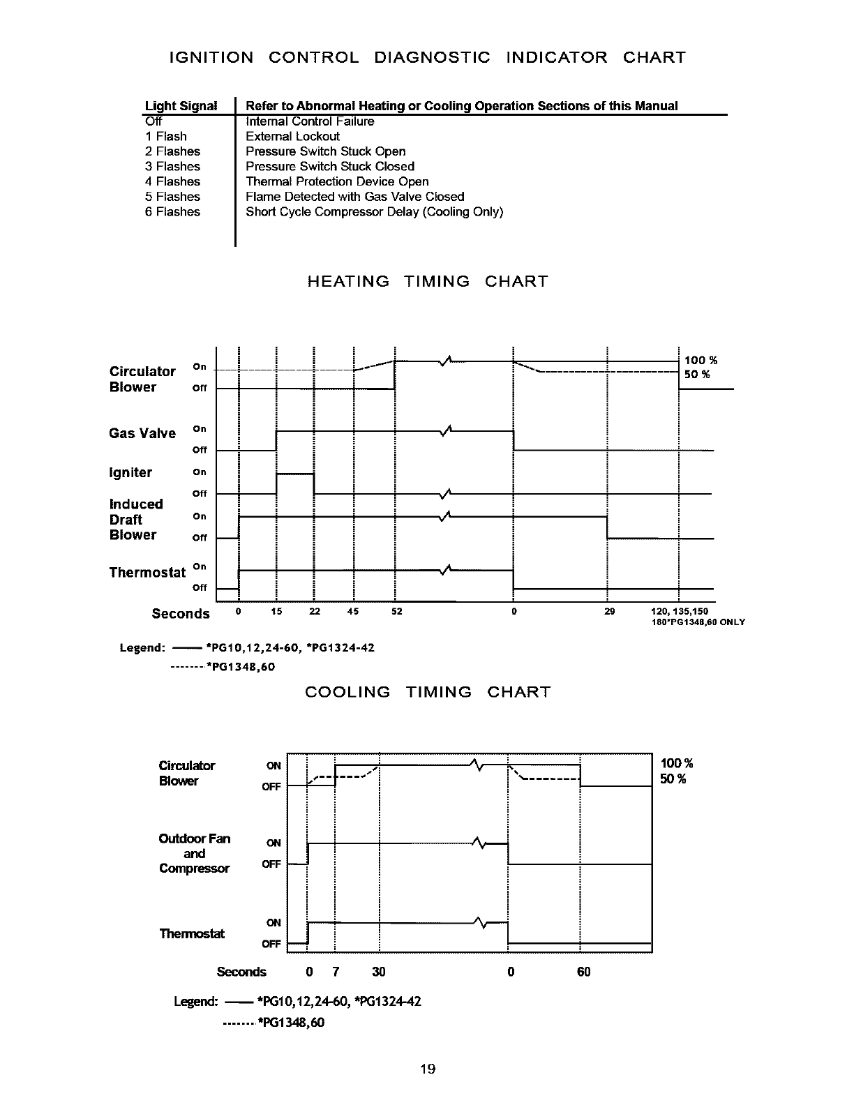
IGNITION CONTROL DIAGNOSTIC INDICATOR CHART
Light Signal
Off
1 Flash
2 Flashes
3 Flashes
4 Flashes
5 Flashes
6 Flashes
Refer to Abnormal Heating or Cooling Operation Sections of this Manual
internal Control Failure
External Lockout
Pressure Switch Stuck Open
Pressure Switch Stuck Closed
Thermal Protection Device Open
Flame Detected with Gas Valve Closed
Short Cycle Compressor Delay (Cooling Only)
HEATING TIMING CHART
Circulator On
Blower off
Gas Valve On
Off
Igniter On
off
Induced
Draft On
Blower off
Thermostat On
Off
i i
i
i
i i
iI
ii
i i i i
i i i i i i
Seconds 015 22 45 52 0
i
i
20
Legend: --*PG10,12,24-60, *PG1324-42
........ *PG1348,60
COOLING TIMING CHART
100 %
50 %
i
i
120, 135,150
180"PG1348,60 ONLY
Circulator
Blower
OutdoorFan
and
Compressor OFF
ON
Thermostat OFF
ON i ,'"i
OFF _ .....
i i
I I
I I
ON J i
i i
ii i
' ' i
i i
1 1
Seconds O 7 30 0
i
i
60
Legend: -- *PGI 0,12,24-60, *PG1324-42
........ *PG1348,60
100%
_%
19
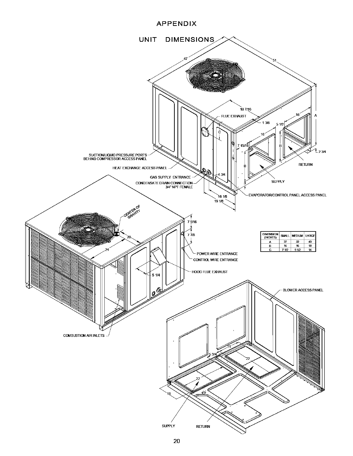
APPENDIX
UNIT DIMENSIONS
BEHIND COMpREssOr ACCESS PAikE L
COIVlBUSTION ,_IR INLETS
REIURN
SUPPLY
SUPPLY REllJRN
2O
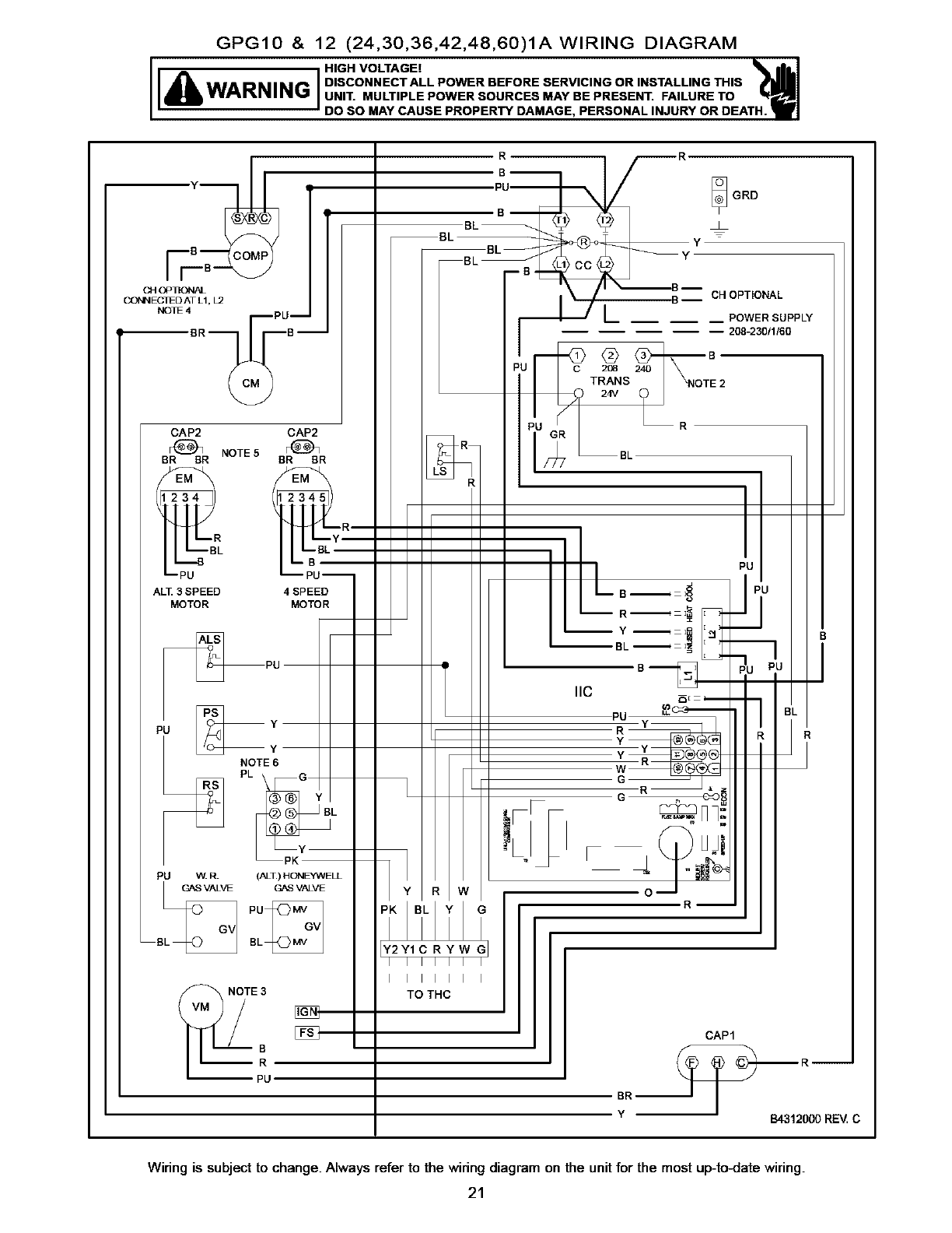
GPG10 & 12 (24,30,36,42,48,60)1AWIRING DIAGRAM
I_HIGH VOLTAGE! ATH._1
WARNING DISCONNECTALLPOWERBEFORESERVICINGORINSTALLINGTHIS
UNIT. MULTIPLE POWER SOURCES MAY BE PRESENT. FAILURE TO
DO SO MAY CAUSE PROPERTY DAMAGE, PERSONAL INJURY OR DE
C_ OP_ONAL
CONNEC1ED AT L1, L2
NOI_4BR C_M PUB-
R
Bm
PU-- _ GRD
Bk Bk B Y
BL
B-- CH OPTIONAL
LPOWER SUPPLY
-- 208-23011160
CAP2 CAP2
BRF(_IBR NOTE5 BRF_BR
BR BL Y
PU
i
_ B
GAS VALVE GAS VALVE
%PU
BBL
_/_ T_A_NS 22_NOT_ 2
24v R
BL
NOTE 3
Y2Y1CRYW G
I IIIII I
I IIIII I
TO THC
BR
Y
CAP1
B4312000 REM C
Wiring is subjectto change.Always refer to the wiringdiagramon the unitfor the most up-to4:latewiring.
21
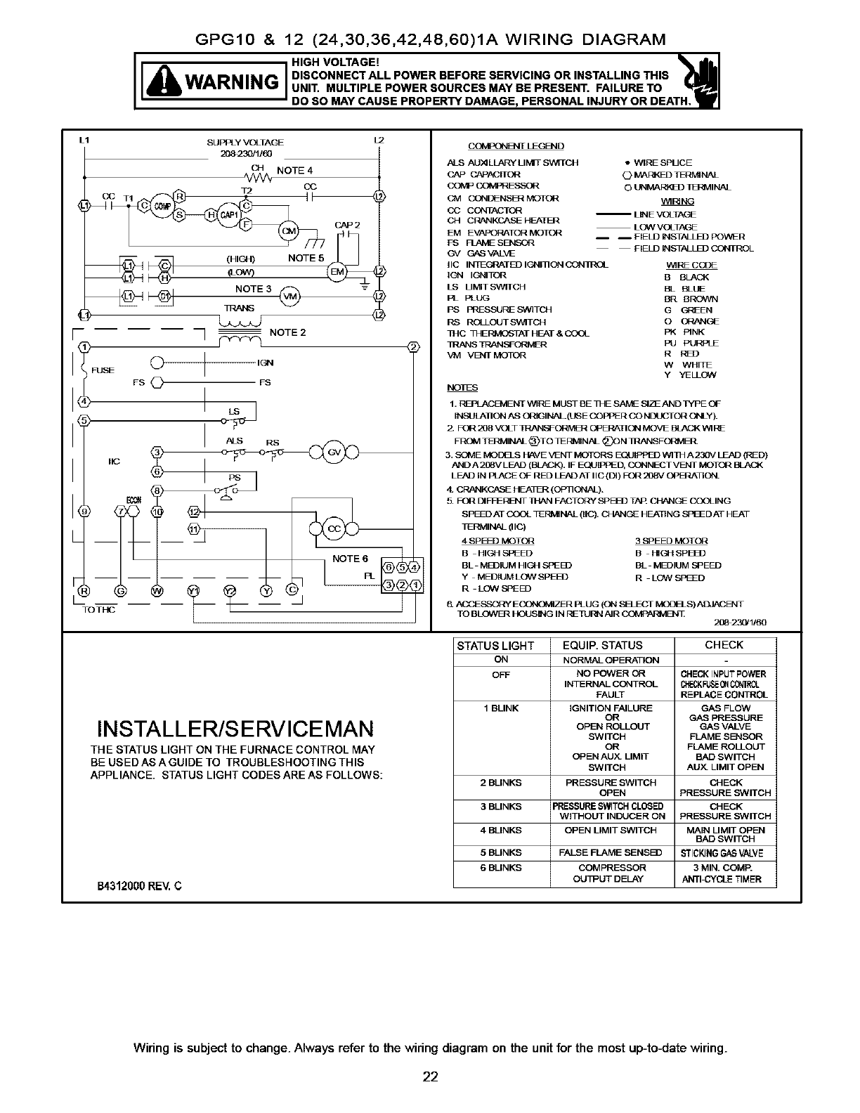
GPG10 & 12 (24,30,36,42,48,60)1A WIRING DIAGRAM
WARNING DISCONNECTALLPOWERBEFORESERVICINGORINSTALMNGTHIS
UNIT. MULTIPLE POWER SOURCES MAY BE PRESENT. FAILURE TO
DO SO MAY CAUSE PROPERTY DAMAGE, PERSONAL INJURY OR DEATH.
SUPPLY VOLTAGE
20_230/1/_
L1
(HIGH) NOTE 5
(LOW)
L2
INSTALLER/SERVICEMAN
THE STATUS LIGHT ON THE FURNACE CONTROL MAY
BE US ED AS A GUIDE TO TROUBLESHOOTING THIS
APPLIANCE. STATUS LIGHT CODESAREAS FOLLOWS:
B4312000RE_C
COVI_3_B_IT LEGEND
ALS AU)aLLARY LIMIT swr[cH
CAP C/McAC rl OR
COMP COMPP_SSOR
QVl CONI]E NSER MOTOR
CO CONTACTQ_
OH CRANKCASE HEATER
EM EVAPORATOR MOTOR
FS FLAME SENSOR
GV GAS VALVE
IIC INTEGRATED IGNI]ION CON]ROL
IC_I IGNITOR
LS LIMIT SWITCH
PL PLUG
PS PRFSSURE SW1TOH
RS ROLl OUT SWITCH
THC THERIVtC_TAT HEAT & COOL
]RANS TRANSF43RIV[_
VM VENT MOTOR
• WIRE SPUCE
(_ MAI3J_D TL=R_NAL
O UNM.ARK_3 I]3_MINAL
V_II_ NG
-- LINE VOLTAGE
LOW VOLTAGE
-- -- FIELD INSTALLS) POWER
FIELD INSq ALLB3 CONTROL
WIRF CCOE
B
BL BLUE
BR BROWN
G GREEN
O ORANGE
PK PINK
PU PURPLE
R PJl3
W WHITE
Y YELLOW
NOES
1. REPLACEMENT WIRE MUST BE THE St'ME SIZE AND TYPE OF
INSUtAI]ON AS ORIGINAL (t_ E COPPER CO NDUCTOR ONLY).
2. FOR 208 VOLT TRANSF_ OPERATION MOVE BLACK WIRE
FROM TI3RMINAL _TO TLNMIN_ _)ON R_ISFO_IMER
3. SOME MOD_S I_VE VENT MOII_tS E_!/IPPED WITH A230V LEAD {RED)
AND A 2_V LFAD (BLACK). IF EGt/IPPED, CONNEC• VENT MO 1t3R BLACK
LEAD IN PLACE OF RED LEAD AT IIC (DI) FOR 208V OPEI:_TION.
& GP_NK_ HEAT_I (OPTION,_).
5. FOR _ _ ND',IT _ FACTONY ._P FfI? TAP. CI_NG_ COOLING
SPED AT COOL TENMINAk (llC_ _ HF_.TI NG NFI_ D AT HEAT
I_RMIN_ (lie)
4 SPHZD MOTOR 3 SPEED MOTOR
BHICNt NI:_ED BI_GH SP_
BL Mt_IUMHIGHSI:_I_ BL MEDIUM_E_
YMEDIUM LOW SPEED RL_ SFI_D
&ACeESSONY EC_%NOMIZFR PLUG (ON SI_ECT MOO_N) AI_I,_JqT
TO BLO_J:t HOUSING IN I_ I1J_N AIR _I_N1. 2_23_1/60
STATUS LIGHT EQUIP. STATUS CHECK
ON NORMAL OPERATION
OFF NO POWER OR CHECK INPUT POWER
INTERNAL CONTROL C}'_K F_P_EONCONIC[
FAULT REPLACE CONTROL
1 BLINK IGNITION FAILURE GAS FLOW
OR GAS PRESSURE
OPEN ROLLOUT GAS VALVE
SWITCH FLAME SESNSOR
OR FLAME ROLLOUT
OPEN AUX. LIMIT BAD SWITCH
SWITCH AUX. LIMIT OPEN
2BLINKS PRESSURE SWITCH CHECK
OPEN PRESSURE SWITCH
3 BLINKS PRESSURE SWITCH CLOSED CHECK
WITHOUT INDUCER ON PRESSURE SWITCH
4 BLINKS OPEN LIMIT SWITCH MAIN LIMIT OPE_I
BAD SWITCH
5 BLINKS FALSE FLAME SENSE-_ STICKING GAS VALVE
6 BLINKS COMPRESSOR 3 MIN. COMP.
OUTPUT DELAY ANTI-CYCLE TIMER
Wiring is subject to change. Always refer to the wiring diagram on the unit for the most up-to4date wiring.
22
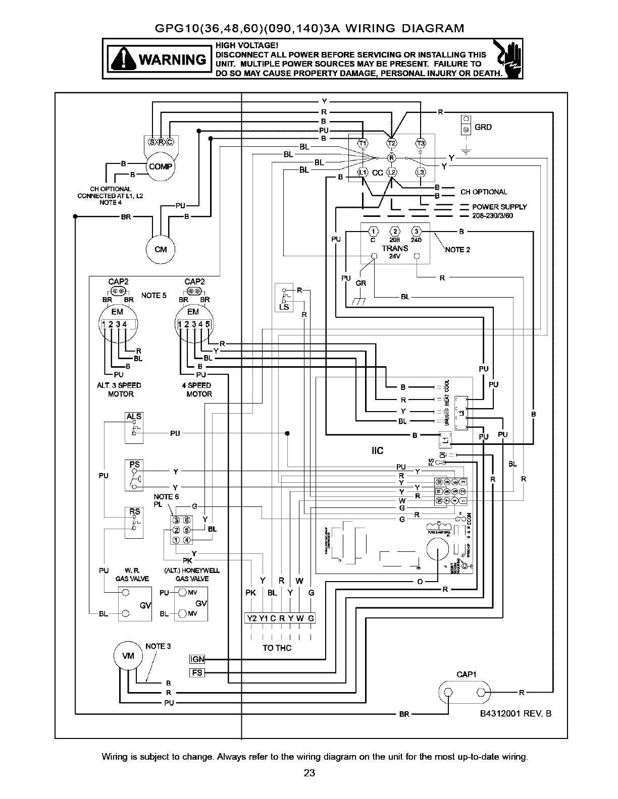
GPG10(36,48,60)(090,140)3A WIRING DIAGRAM
IEA I
WARNING DISCONNECTALLPOWERBEFORESERVICINGORINSTALLINGTHIS
UNIT. MULTIPLE POWER SOURCES MAY BE PRESENT. FAILURE TO
DO SO MAY CAUSE PROPERTY DAMAGE, PERSONAL INJURY OR DEATH.
B (
CH OPTIONAL
CONNECTED AT L1, L2
NOTE 4
BR B--
I
CAP2 CAP2
NOTF5
BR BR BR BR
BL
ALI_3 SPEED 4SPEED
MOTOR MOTOR
PU W.P. (ALT.)HONEYWELL
GASVALVE GASVALVE
B BL
¢ L
I IIIII I
NOTE 3
NN
B
R
PU
TO THC
BR--
CAP1
_IRREv. B
Wiring is subject to change. Always refer to the wiring diagram on the unitfor the most up-to-datewiring.
23
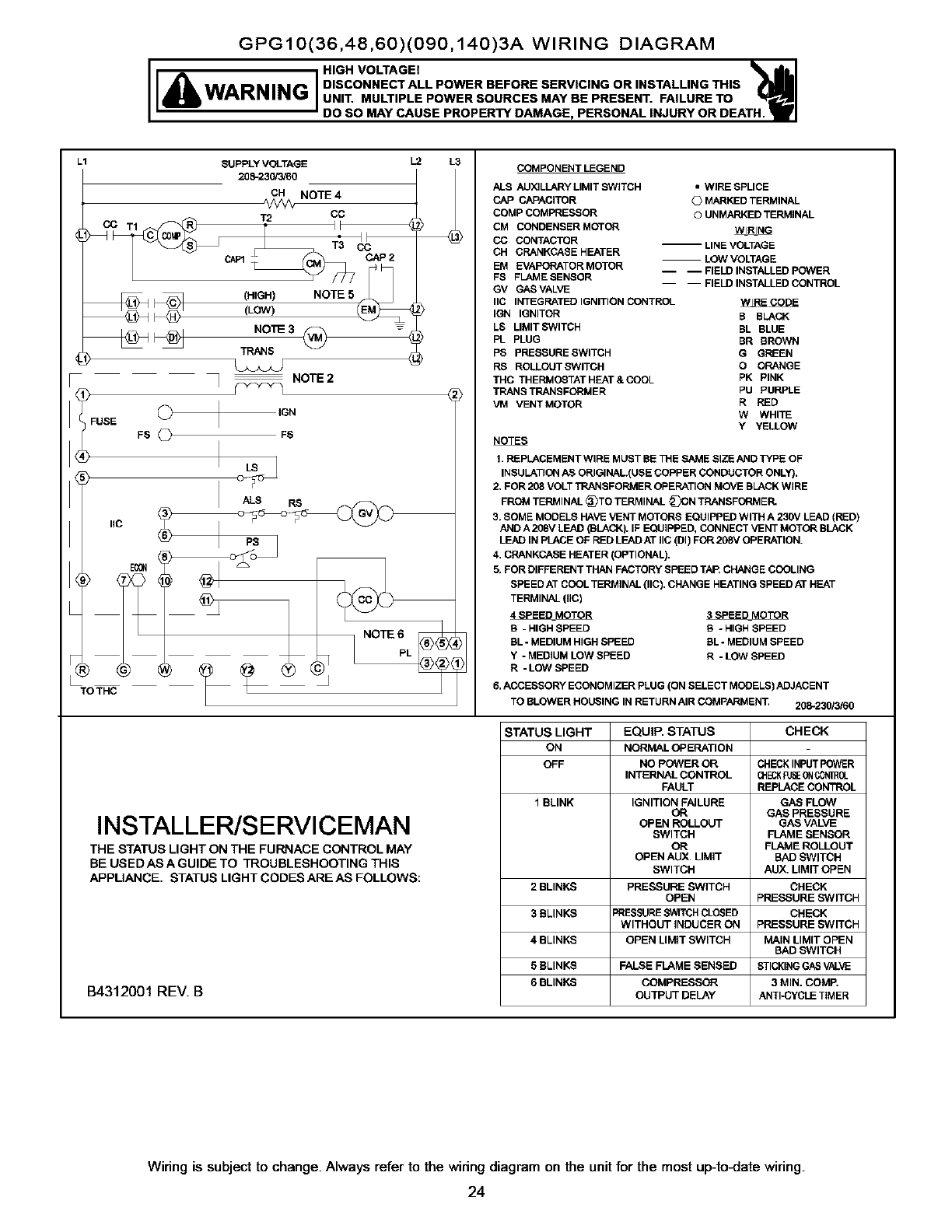
GPG10(36,48,60)(090,140)3A WIRING DIAGRAM
IEA 1
WARNING DISCONNECTALLPOWERBEFORESERVICINGORINSTALUNGTHIS
UNIT. MULTIPLE POWER SOURCES MAY BE PRESENT. FAILURE TO
DO SO MAY CAUSE PROPERTY DAMAGE, PERSONAL INJURY OR DEATH.
L1 SUPPLY VOLTAGE
208-230/3/60
CH NOTE 4
T2 CC
CC TI_ f II
@ _ (HIGH) NOTE 5_ ,
_<_ (LOW) I_
TN,_IS
NOTE 2
FUSE
L.2 L3
2)
_) IGN
FS _FS
TO THC
INSTALLER/SERVICEMAN
THE STATUS LIGHT ON THE FURNACE CONTROL MAY
BE USED AS A GUIDE TO TROUBLESHOOTING THIS
APPLIANCE, STATUS LIGHT CODES ARE AS FOLLOWS:
B4312001 REV. B
COMPONENT LEGEND
ALS AUXILLARY LIMIT SWITCH •WIRE SPLICE
CAP CAPACITOR GMARKED TERMINAL
COMP COMPRESSOR ©UNMARKED TERMINAL
CM CONDENSER MOTOR WIRING
CO CONTACTOR -- LINE VOLTAGE
CH CRANKCASE HEATER LOW VOLTAGE
EM EVAPORATOR MOTOR -- -- FIELD INSTALLED POWER
FS FLAME SENSOR
GV GAS VALVE FIELD INSTALLED CONTROL
IIC INTEGRATED IGNITION CONTROL _.E CODE
IGN IGNITOR B BLACK
LS LIMIT SWITCH BL BLUE
PL PLUG BR BROWN
PS PRESSURE SWITCH G GREEN
RS ROLLOUTSWITCH O ORANGE
THC THERMOSTATHEAT&COOL PK PINK
TRANS TRANSFORMER PU PURPLE
VM VENTMOTOR R RED
W WHITE
Y YELLOW
NOTES
1. REPLACEMENT WIRE MUST BE THE SAME SIZE AND TYPE OF
INSULATION AS ORIGINAL(USE COPPER CONDUCTOR ONLY).
2, FOR 208 VOLT TRANSFORMER OPERATION MOVE BLACK WIRE
FROM TERMINAL _TO TERMIRAL _ON TRANSFORMER.
3, SOME MODELS HAVE VENT MOTORS EQUIPPED WITH A 230V LE,AD (RED)
AND A 208V LEAD (BLACK). IF EQUIPPED, CONNECT VENT MOTOR BLACK
LEAD IN PLACE OF RED LEAD AT IIC (DI) FOR 208V OPERATION.
4. CRANKCASE HEATER (OPTIONAL).
5, FOR DIFFERENT THAN FACTORY SPEED TAP, CHANGE COOLING
SPEED AT COOL TERMINAL (IIC), CHANGE HEATING SPEED AT HE.AT
TERMINAL (IIC)
4SPEED_MOTOR 3SPEED MOTOR
S-HIGH SPEED S - HIGH SPEED
BL - MEDIUM HIGH SPEED BL - MEDIUM SPEED
Y-MEDIUM LOW SPEED R-LOW SPEED
R-LOW SPEED
6. ACCESSORY ECONOMIZER PLUG (ON SELECT MODELS) ADJACENT
TO BLOWER HOUSING IN RETURN AIR COMPARMENT 208-230/3/60
STATUS LIGHT EQUIP, STATUS CHECK
ON NORMAL OPERATION
OFF NO POWER OR CHECKINPUT POWER
INTERNAL CONTROL CHECK_E 0NC_ROL
FAULT REPLACE CON'mOL
1 BLINK IGNITION FAILURE GAS FLOW
OR GAS PRESSURE
OPEN ROLLOUT GAS VALVE
SWITCH FLAME SENSOR
OR FLAME ROLLOUT
OPEN AUX. LIMIT BAD SWITCH
SWITCH AUX, LIMIT OPEN
2 BLINKS PRESSURE SWITCH CHECK
OPEN PRESSURE SWITCH
3BLINKS _RESSURESWITCHCLOSED CHECK
WITHOUT INDUCER ON PRESSURE SWITCH
4 BLINKS OPEN LIMIT SWITCH MAIN LIMIT OPEN
BAD SWITCH
5 BLINKS FALSE FLAME SENSED STICKINGGASVALVE
6 BLINKS COMPRESSOR 3 MIN. COMP.
OUTPUT DELAY ANTI-CYCLE TIMER
Wiring is subjectto change.Always refer to the wiringdiagramon the unitfor the mostup-to.late wiring.
24
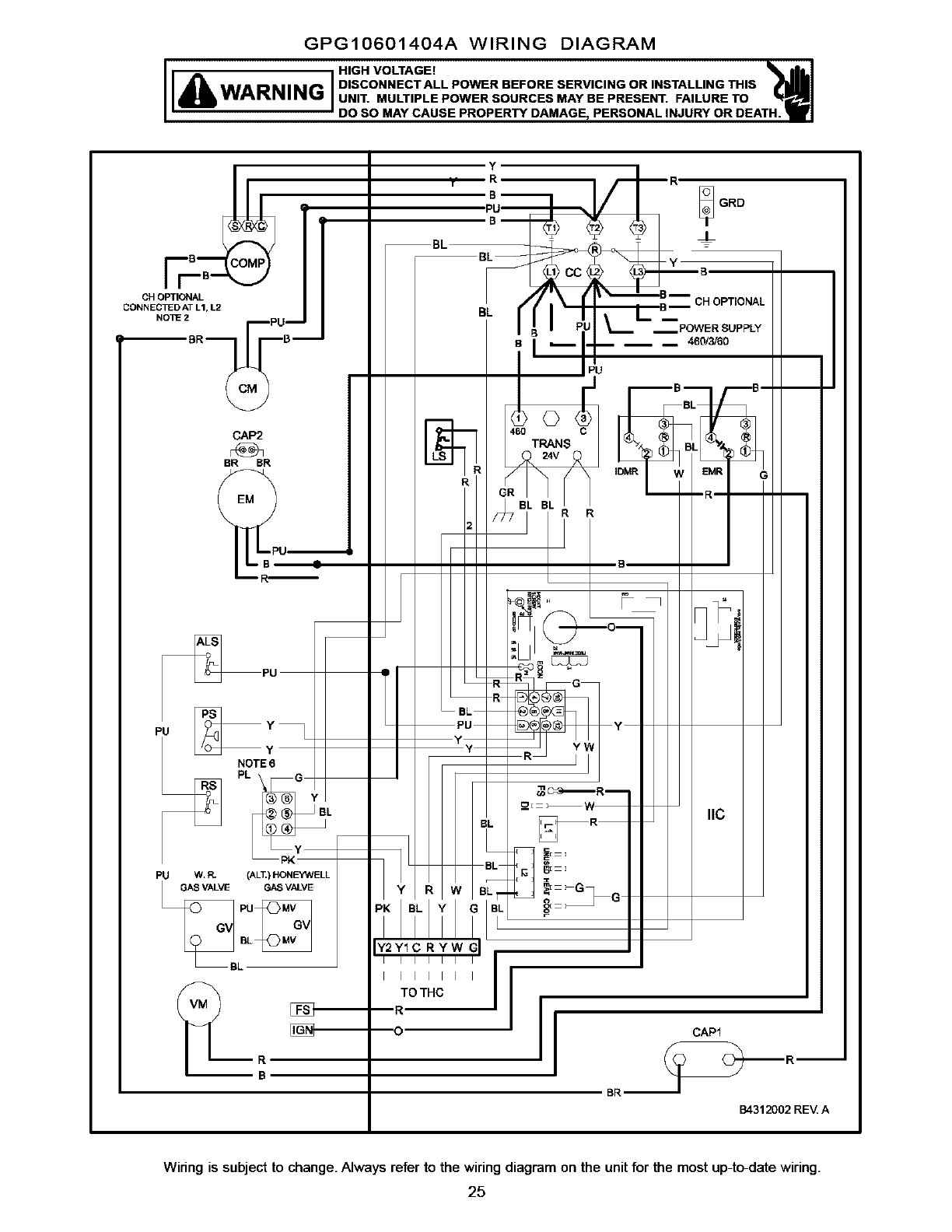
GPG10601404A WIRING DIAGRAM
HIGH VOLTAGE!
I
WARNING '1DISCONNECTALLPOWERBEFORESERVICINGORINSTALLINGTHIS
UNIT. MULTIPLE POWER SOURCES MAY BE PRESENT. FAILURE TO
I DO SO MAY CAUSE PROPERTY DAMAGE, PERSONAL INJURY OR DEATH.
B(
CHOPTIONAL
CONNECTEDATL1,L2
NOTE2BR._UB_
CAP2
BR BR
PU W, _(ALT.) HON_ELL
G_ VAL_ G_ VALVE
BL
LBL I I I I I I
TO THC
mR
[_'_ "_O
R
B
1
m
B4312002 REV A
Wiring is subjectto change.Always refer to the wiringdiagramonthe unitfor the most up-to-datewiring.
25
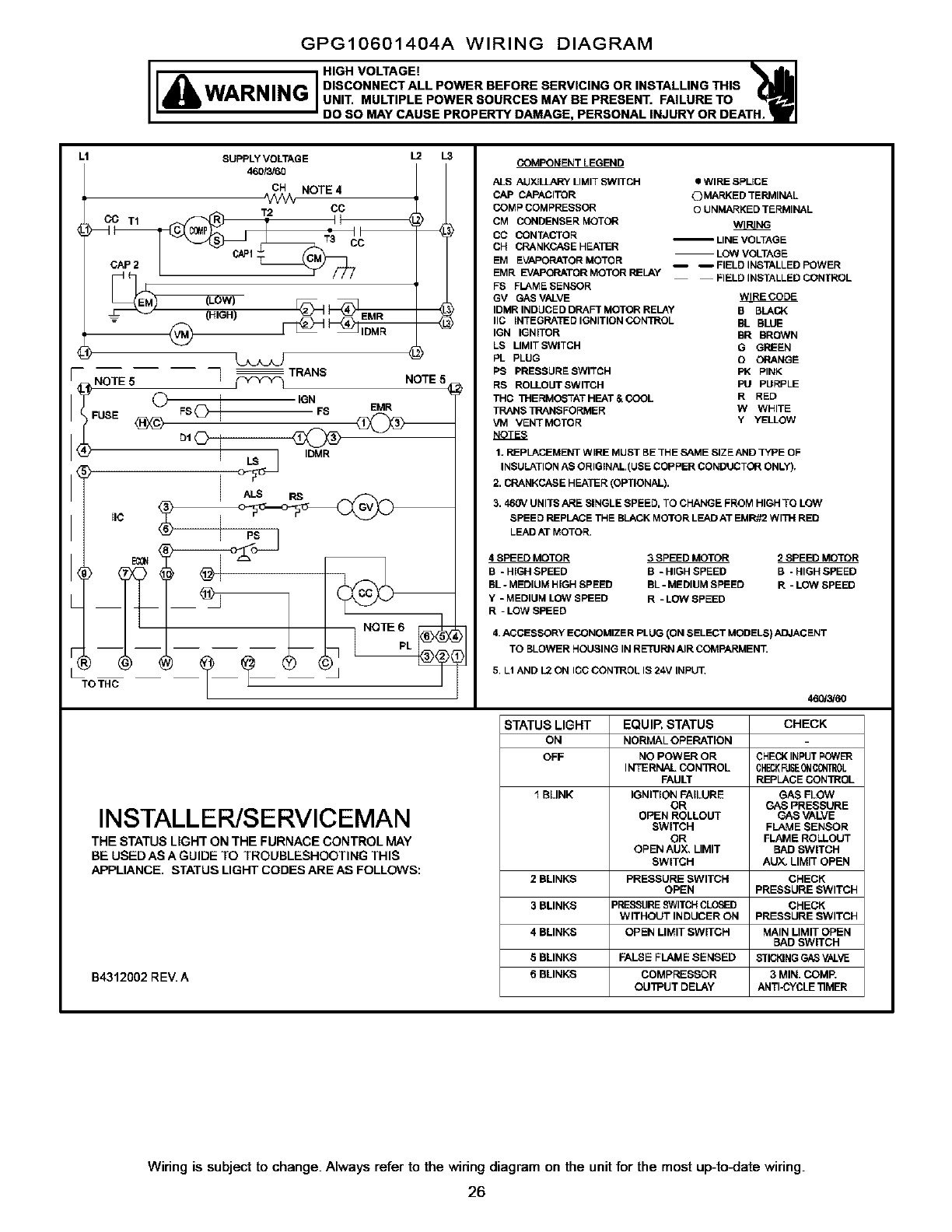
GPG10601404A WIRING DIAGRAM
HIGH VOLTAGE!
DISCONNECT ALL POWER BEFORE SERVICING OR INSTALLING THIS
UNIT. MULTIPLE POWER SOURCES MAY BE PRESENT. FAILURE TO
DO SO MAY CAUSE PROPERTY DAMAGE, PERSONAL INJURY OR DEATH.
L1 SUPPLY VOLTAGE L2 L3
460/_C_ NOTE 4 1
CAP 2 CAP1 •
_NOTE50 =.F_ I' _r::::o EaR NOTE,
NOTE 6pL
TOTHC _ _
INSTALLER/SERVICEMAN
THE STATUS LIGHT ON THE FURNACE CONTROL MAY
BE USEDAS A GUIDE TO TROUBLESHOOTING THIS
APPLIANCE. STATUS LIGHT CODES ARE AS FOLLOWS:
B4312002 RE_ A
COMPONENT LEGEND
ALS AUXJ_ LIMIT S_NITCH
CAP CAPACITOR
COMP COMPRESSOR
CM CONDENSER MOTOR
CC CONTACTOR
CH CRANKCASE HEATER
EM EVAPORATOR MOTC R
EMR EVAPORATOR MOTOR RELAY
FB FL_ME SENSOR
GV GAS VALVE
IDMR INDUCED DRAFT MOTOR RELAY
IIC INTEGRATE D IGNITION CONTROL
IGN IGNITOR
LS LIMIT SWITCH
PL PLUG
PS PRESSURE SWITCH
RS ROLLOUT SWITCH
THC 1HERMOSTAT HEAT &COOL
TRANS 1RANSFORMER
VM VENT MOTOR
NOTES
•WIRE SPLICE
OMARKED TERMINAL
OUNMARKED TERMINAL
WIRING
LOW VOLTAGE
mFIELD INSTALLED POWER
FIELD INSTALLED CONTROL
WIRE CODE
B SLACK
BL BWE
BR BROWN
GGREEN
OORANGE
PK PINK
PU PURPLE
R RED
W WHITE
Y YELLOW
1. REPLACEMENT WIRE MUST BE TH ESAME SIZE AND ]YPE OF
INSULATION AS ORIGINAL(USE COPPER CONDUCTOR ONLY),
2. CP_NKCABE HEATER (OPTIONAL).
3. 460V UNITE ARE SINGLE SPEED, TO CHANGE FROM HIGH TO LOW
SPEE DREPLACE THE BLACK MOTOR LEAD AT EMR_2 WITH RED
LEAD AT MOTOR.
4 SPEED MOTOR 3 SPEED MOTOR 2SPEED MOTOR
B-HIGH SPEED B -HIGH SPEED B- HIGH SPEED
BL -MEDIUM HIGH SPEED BL -MEDIUM SPEED R -LOW SPEED
Y-MEDIUM LOW SPEED R -LOP/SPEED
R=LOW GPEED
4. ACCESSORY ECONOMIZER PLUG (ON SELECT MODELS) ADJACENT
TO SLOWER HOUSING IN RETURN AIR COMPARMENT.
5, LI AND L2 ON ICC CON]ROL IS 24V INPUT,
46_60
STATUS LIGHT EQUIP, STATUS CHECK
ON NORMAL OPERATION
OFF NO POWER OR CHECK INPUT P_ E_R
INTERNAL CONTROL CHECKFUSEON_0L
FAULT REPLACE CONTROL
1 BLINK IGNITION FAILURE GAS FLOW
OR GAS PRESSURE
OPEN ROLLOUT GAS VALVE
SWITCH FLAME SENSOR
OR FLAME ROLLOUT
OPEN AUX, LIMIT BAD SWITCH
SWITCH AUY_ LIMIT OPEN
2 BLINKS PRESSURE SWITCH CHECK
OPEN PRESSURE SWITCH
3 BLINKS PRESSURESWITCHCLOSED CHECK
WITHOUT INDUCER ON PRESSURE SWITCH
4 BLINKS OPEN LIMIT SWITCH MAIN LIMIT OPEN
BAD SWITCH
E BLINKS FALSE FLAME SENSED STICKINGGAS VALVE
6 BLINKS COMPRESSOR 3 MIN. COMP.
OUI_UT DELAY ANTI_:YCLE 11MER
Wiring is subjectto change.Always refer to the wiringdiagramon the unitfor the mostup-to.late wiring.
26
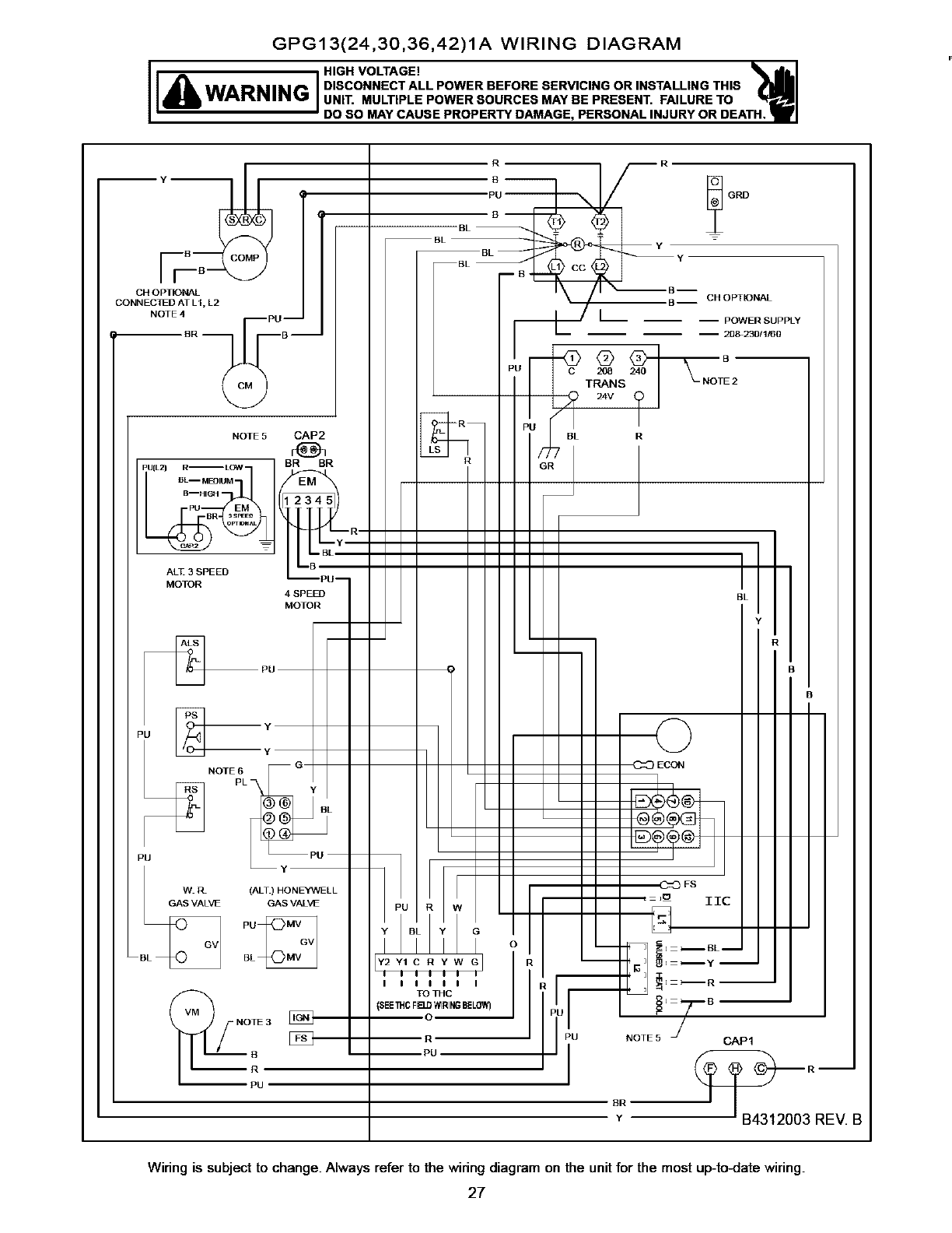
GPG13(24,30,36,42)1A WIRING DIAGRAM
IIA I
WARNING DISCONNECTALLPOWERBEFORESERVICINGORINSTALLINGTHIS
UNIT. MULTIPLE POWER SOURCES MAY BE PRESENT. FAILURE TO
DO SO MAY CAUSE PROPERTY DAMAGE, PERSONAL INJURY OR DE
CH OPTIONAL
CONN EC_D AT LI, L2
r
i
NOTE4
BR
PU
NOTE 5 CAP2
BN BR
ALT3SPEED
MOTOR 4 SPEED
NOTE6
PL
MOTOR
OTE 3
!o
Y2Y1C RYW
IIIII I
TO THC
DEETHC F_D WIRINGBELOW)
POWER SUPPLY
20_230/1/60
C 208
TRANS 2
24V
BL r
BL
B
ECON
IIC
N
'U NOTE5 CAP1
--R--
B4312003 REV. B
Wiring is subjectto change.Always refer to the wiringdiagramon the unitfor the most up-to.late wiring.
27
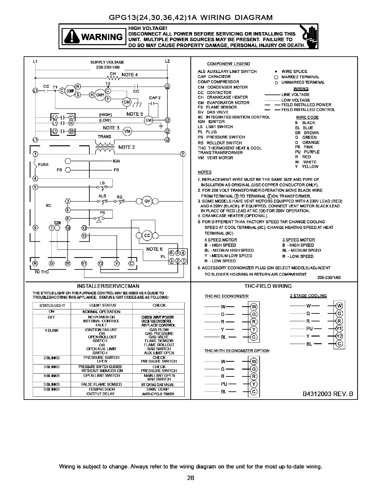
GPG13(24,30,36,42)1A WIRING DIAGRAM
HIGH VOLTAGE!
I
WARNING '1DISCONNECT ALL POWER BEFORE SERVICING OR INSTALLING THIS
UNIT. MULTIPLE POWER SOURCES MAY BE PRESENT. FAILURE TO
JDO SO MAY CAUSE PROPERTY DAMAGE, PERSONAL INJURY OR DEATH.
SUPPLY VOLTAGE
208-230/1/60
L1 L2
CH NOTE 4
1_--4_ cAP2
__ (HIGH)(LOW) NOTE 5 (EM_
i__1 1NOTE 3@ 4
TRANB 4
]NOTE
II USE O ,GN
FB OFB
ALS RS
IIC
TOTHC Z (__" _ _]J
INSTALLER/SERVICEMAN
THE STATUS UGHT ON THE FURNACE CON_OL MAY BE USES A_ AGUIDE TO
TROUSLESHOO]]NG THIS APPLIANCE STATJB LIGHT COBES ARE AS FOLLOWS:
STATUS UGHT EQUIE STATUS CHECK
ON NQRMAL OPERATION
OFF NO POWER OR SH£-_KINRJT POWER
II_TIERNAL CONTROL _E_ 'DEON _0_]R_
FAULT REPLACE CONTROL
1 SUNK IG NITIQN FAILURE GAS FLOW
OR G_.S PRESSURE
OPEN R(g[LC_rl GAS VALVE
SWITCH FLAME SENSOR
OR FLAME ROLLOUT
OPEN AUX UMIT BAD SWITCH
SWITCH AUX UMIT OPEN
2 BLINKS PRFSSURE SWITCH CHECK
OPEN PRFSSURF SWITCH
3BLINKS PRESSURESWrrBH CLOSED CFECK
Wl IHOUT INI_JCl]_ ON PRESSURE SWITCH
4BLINKS OITLN LIMIT SWITCH N_IN LIMIT OPEN
BAD SWITCH
5 BLINKS FALSE FLAME SENSED SflCNING G_8 VALVE
6BLINKS COMPRESSOR 3 MIN COMP
OLrfPUT DELAY ANTI-CYCLE TIMER
COMPONENT LEGEND
ALS AUXILLARY LIMIT SWITCH o WIRE SPLICE
CAP CAPACITOR O MARleD TERMINAL
COMP COMPRESSOR OUNMARKED llERMINAL
CM CONDENSER MOTOR WIRING
CC CO NTACTO R -- LINE VOLTAGE
CH CRANKCASE HEATER LOW VOLTAGE
EM EVAPORATOR MOTOR -- -- FIELD INSTALLED POWER
FS FLAME SENSOR -- -- FIELD INSTALLED CONTROL
GV GAB VALVE
BC INTEG RATED IGNITION CO NTROL WIRE CODE
;GN IGNITOR B BLACK
LS LIMITSWlTCH BL BLUE
PL PLUG BR BROWN
PS PRESBURESWITCH G GREEN
RB ROLLOLFrSWlTCH O ORANGE
THC THERMOSTAT HEAT & COOL PK PINK
TRANS TRANSFORMER PU PURPLE
VM VENT MOTOR R RED
W WHITE
Y YELLOW
NOTES
1. REPLACEMENT WIRE MUST BE THE SAME SIZE AND TYPE OF
INSULATION AS ORIGINAL(USE COPPER CONDUCTOR ONLY).
2. FOR 208 VOLT TRANSFORMER OPERATION MOVE BL&CK WIRE
FROM TERM INAL _) TO TERMINAL DON TRANSFORMER.
3. SOME MODELS HAVE VENT MOTORS EQUIPPED WITH A 23DV LEAD (RED)
AND A 208V (BLACK). IF EQUIPPED, CONNECT VENT MOTOR BLACK LEAD
IN PLACE OF RED LEAD AT IIC (DI) FOR 208V OPERATION.
4. CRANKCASE HEATER (OPTIONAL).
5. FOR DIFFEI_ENT THAN FACTORY SPEED TAR CHANGE COOLING
SPEED AT COOL TERMINAL (IIC). CHANGE H EA33 NG SPEED AT HEAT
TERMINAL (llC)
4SPEED MOTOR 3 SPEED MOTOR
B - HIGH SPEED B - HIGH SPEED
BL - MEDIUM HIGH SPEED BL - MEDIUM SPEED
Y - MEDIUM LOW SPEED R - LOW SPEED
R - LOW SPEED
6. ACCESSORY ECONOMIZER PLUG (ON SELECT MODELS)ADJACENT
TO BLOWER HOUSING IN RETURN AIR COM PAR M ENT. 208-230/1/60
THC-FIELD WIRING
THC-NO ECONOMIZER
G--
R--
y--
--BL --
THC-WITH ECONOMIZER OPTION
G--
R--
PU--
BL--
2 STAGECOOLING
G-- ---_)
R-- ---(_
PU -- -- "@
y-- ---@
BL -- -- -@
B4312003 REV. B
Wiring is subjectto change.Always refer to the wiringdiagramon the unitfor the most up-to4datewiring.
28
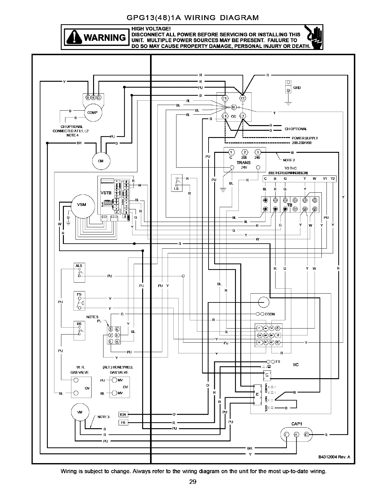
GPG13(48)1A WIRING DIAGRAM
II _HIGH VOLTAGE!
WARNING DISCONNECTALLPOWERBEFORESERVICINGORINSTALLINGTHIS
I UNIT. MULTIPLE POWER SOURCES MAY BE PRESENT. FAILURE TO
DO SO MAY CAUSE PROPERTY DAMAGE, PERSONAL INJURY OR DEATH.
OPTIONAL
CONNEC/_O AT L1, L2
NOLO4
[_PU
Y
NOI_ 5
PL
PU
W3_ (ALT) HONEYWELL
GAS VAI VE GAS VALVE
Pu
i
I
R
PU y
0
(_] OPTIONAL
pOWER SUPPLy
|............................ 2(]8_30/1/60
BR
Y
Q
C206
TRANS
24V
PU
I
2411
TOIHC
R G Y W Y1 Y2
BL RG Y
RG Y W
IIC
CAP1
B4312004 Rev. A
Wiring is subjectto change.Always refer to the wiringdiagramon the unitfor the mostup-to.ate wiring.
29
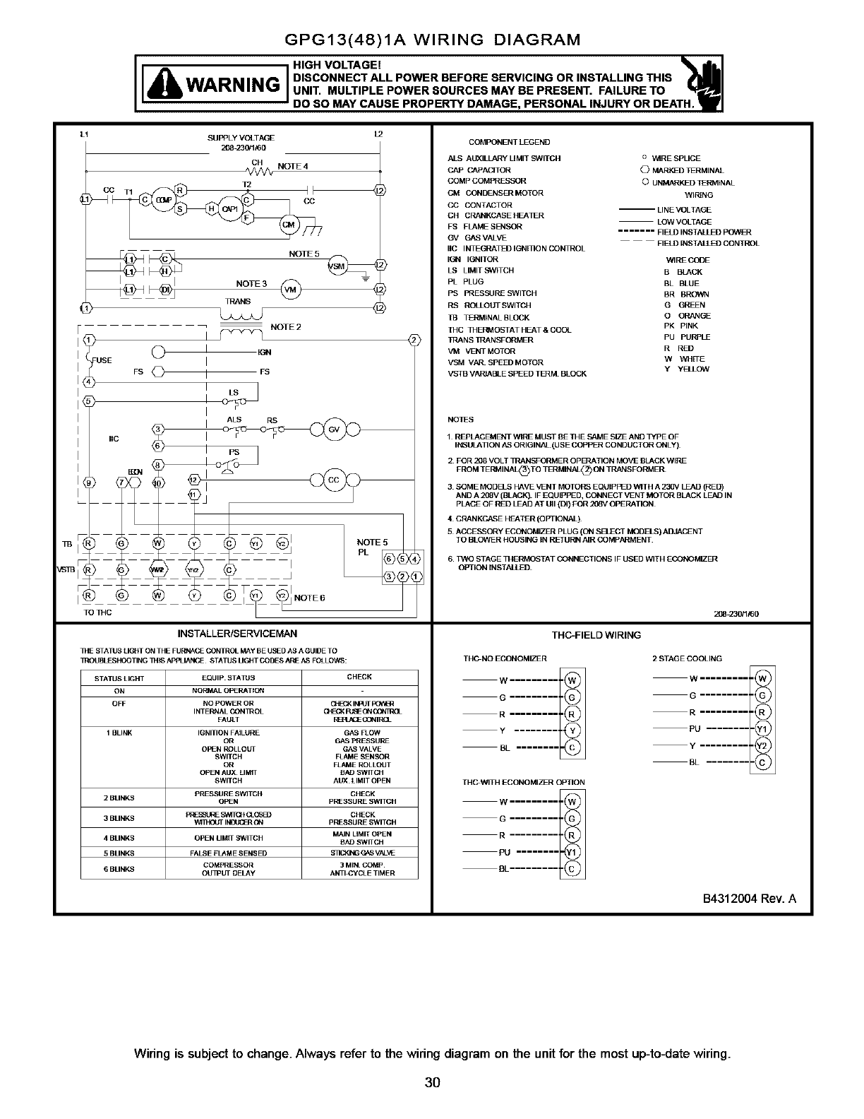
GPG13(48)1A WIRING DIAGRAM
WARNING]
HIGH VOLTAGE!
DISCONNECT ALL POWER BEFORE SERVICING OR INSTALLING THIS
UNIT. MULTIPLE POWER SOURCES MAY BE PRESENT. FAILURE TO
DO SO MAY CAUSE PROPERTY DAMAGE, PERSONAL INJURY OR DEATH.
L1 SUPPLY VOLTAGE
208 230/1/60
CH NOTE 4
NOTE 2
t
I tGN
I
I FS
I
IALS RS
i USE Q
FS O
IIC
NOTE6
TO THC
INSTALLER/SERVICEMAN
I_E STATUS LIGHT ON THE FURNACE CONTROL MAy BE USED AS A GUIDE TO
]ROL_LESHOOTING ]HIS APPLIANCE STATUS UG_IT CODES ARE AS FOLLOWS:
STATUS LIGHT EQUIP STATOS CHECK
ON NORMAL OPERATION
OFF NO POWER OR C_EGK INFUT pOV_
G_cCK RJSE ON (30N]g(1
FAULT RBPL_E GON3R_L
1 BLINK IGNITION FPJLURE GAS FLOW
OR GAS PRESSURE
OPEN ROLLOLrl GAS VALVE
SWITCH FLAME _NSOR
OR FLAME ROLLOUT
OPEN AUX UMIT BAD SWITCH
SWITCH ALrX LIMIT OPEN
pRESSURE SWITCH CHECK
2 BLINKS OPEN pRESSURE SWITCH
3 BLINKS PRESSt J_f S_IT(}I C_(3S_ CHECK
IhlBJ_ER ON pRESSURE SWITCH
MAIN LIMIT OPEN
4 BLINKS OPEN LIMIT SWITCH BAD SWITCH
5 BLINKS FALSE FLAME SENSED SlICiNG G_S VAL_IE
COMPRESSOR 3 MIN COMP
GBLINKS OU I?Lrl OELAy ANTI_yCLE TIMER
COMPONENT LEGEND
AIS AL_ILLARy LIMIT S_VlTCH o WtRESPLICE
CAP CAPACITOR O_L_D _RMINAL
COMP COMPRFSSOR O UNMARKED TERMINAL
CM CONDENSER MOTOR WIRING
CC CONTACTOR -- LINE VOLTAGE
CH CRANKCASE HEA I_R LOW VOLTAGE
FS FLAME SE]qSOR ....... FIELD INSTALLED pOWER
GV GAS VALVE FIELO INSTALLED CONTROL
IIC INTEGRATED IGNI I]O N CON]ROL
IGN IGNITOR WIRE CODE
LS LIMITSWITCH B BLACK
PL PLUG BL BLUE
PS PRESSLIRESWITCH BR BROWN
RS RC_LOUTSWlTCH G GREFN
[]} TERMINAL BLOCK O ORANGE
MC MERMO_IATHEAT&COOL PK PINK
_PANS _RANSFORMER PU pUrPLE
VM VENT MOTOR RRED
VSM VAR SPEEDMOTOR WWHrlE
y yELLOW
VSTB VARIABLE SPEED T_M BLOCK
NOTES
1 REPLACEMB_T WIRE MUST BE THE SAME SEF AND TYpE OF
INSULA lION AS ORIGINAl (USE COppER CONDUCTOR ONLy)
2 FOR 208 VOLT IRANSFORMER OpU_ATION MOVE BLACK WIRF
FROM TERMINAL_TO TERMINAL®ON TRANSFORMER
3 SOME MODRS HAVE VENT MOTORS EQUIPPED WITH A 230V LEAD (RED)
AND A 208V (BLACk') IF EQUIPPED, CONNECT VENT MOTOR BLACK LEAD IN
PLACE OF RED LEAD AT UII (DI) FOR 208V OPERATION
4 CRANKCASE HF},TER (OPTIONAl)
5A_E_ORY ECONOMIZER PLUG (ON SD_C1 MODELS) ADJACENT
TO BLOWER HOUSING IN NEI UI_I AIR CO Mp._RMENT
6TWO STAGE MERMOSTAT CONNECTIONS IF USED WITH ECONOMIZER
OPTION INSTALLED
208 230/1/60
THC-FIELD WIRING
THC-NO ECONOMIZER 2 STAGE COOLING
W ......... W ..........
......... R ..........
Po.........@
..........@
BE .........
TH_WlTH ECONOMI_R OPTION
W .........
ZZ
PU ........
BL.........
B4312004 Rev. A
Wiring is subject to change. Always refer to the wiring diagram on the unit for the most up-to.late wiring.
3O
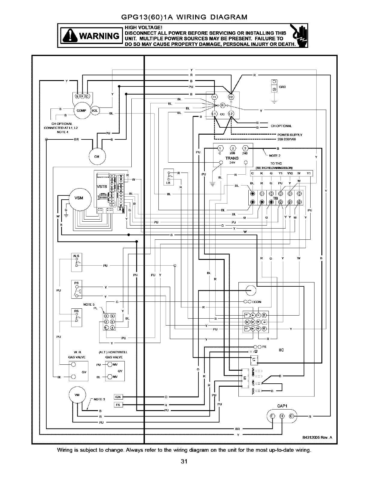
GPG13(60)1A WIRING DIAGRAM
IEA 1+v°++
WARNING DISCONNECTALLPOWERBEFORESERVICINGORINSTALUNGTHIS
UNIT. MULTIPLE POWER SOURCES MAY BE PRESENT. FAILURE TO
DO SO MAY CAUSE PROPERTY DAMAGE, PERSONAL INJURY OR DEATH.
CH OPTIONAL
CONNECTED AT L1, L2
NOTE 4
I_PU
NOIE 5
PU
/
WWA (ALT) HONEWWELL
GAS VALVE GAS VALVE
BBL
Y
A
B
B
BL --
BL
BL
mB
PU Y
B-- CH OPTIONAL
POWER SUppLY
i
i ............................ 208 2301_!60
Q
C238 240
TRANS
TOTHC
(_ IHCRE]DWRNG BtG_
BL
R G Y W
IIC
PU
1
BR
Y
CAP1
BA312005 Rev. A
Wiring is subject to change. Always refer to the wiring diagram on the unit for the most up-to.late wiring.
31
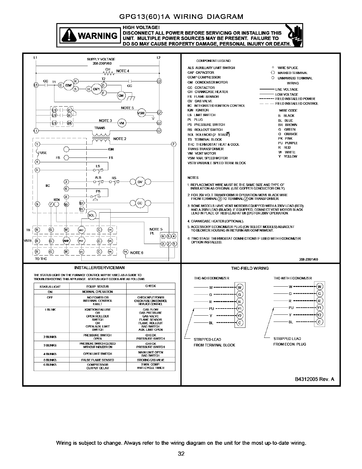
GPG13(60)1A WIRING DIAGRAM
lea 1
WARNING DISCONNECTALLPOWERBEFORESERVICINGORINSTALUNGTHIS
UNIT. MULTIPLE POWER SOURCES MAY BE PRESENT. FAILURE TO
DO SO MAY CAUSE PROPERTY DAMAGE, PERSONAL INJURY OR DEATH.
L1 SUPPLY VOLTAGE
208_30/1/60
INSTALLER/SERVICEMAN
II_E STA11JS UGIIT ON ThE _CE CC_RPOL MAy BE US_) hS AGUIQE TO
I]_0_1 FSP_3OTING ]H IS API_IALNCE STATDS LIGHT CODFS _qE AS FCU O1_:
STAIUS LIGHT EQUIp STAIUS CHECK
ON NOI_MAL OPERA11ON
OFF NO pOWEROR _INPUI POV_q
(_ECI( R_EON CGNlgOL
FAULT /_EPEhCE(3ON]REL
1 BLli_( IGNI11ON FhJLURF GAS FLOW
OR GAS PRF_URE
OPEN ROLl OUT GAS VALVE
SWITCH FLelM E SENSOR
OR FLAME ROLLOUT
OPEN AUX LIMIT BAD _WITCH
SWITCH AUX LIMIT OpD_
pReSSURE SWITCH CHECK
2 BUNKS OPEN pRESSURE S_I]TCH
_SSLIq_ SW[I CH CI (_B) CHECK
3 BUNKS _MIH_JT I_ ON pRESSURE SWITCH
4 BUNKS OPeN UMrl S_alTCH MAIN UMrl OPEN
BAD SWITCH
5 BUi_KS FALSE FU_ME SENSE{] S_ _ V_LVE
6 BU _KS _OMpRE_OR 3 Mli_ COMp
OUIP_I DELAy AN11_yCLE TIMER
COMPONENT LEGEND
AIS AUXILLARY UMIT SWITCH a WIRE SPLICE
CAP CAPACITOR _> MARling TERMINAL
COMp COMPRESSOR ©UNMARKED TERMINAL
CM CONDENSER MOTOR WIRING
CC CONTACTOR m LINE VOLTAGE
CH CRANKCASE HEATER LOW VOLTAGE
FS FLAME SE3qSOR ....... FIELD INSTALLI])POWER
Gq GAS VALVE FIELD [NSTAiIE_ CONTROL
IIC INI_GRATED IGNrllON CONqROL
IGN IGNITOR WIRF CODE
LS LIMITSWITCH B BLACK
PL PLUG BL BLUE
PS PRESSLIRESWITCH BR BROWN
RS ROLIOUTSWlTCH G GREFN
SOL SOLENOID (2 STAG_ O ORANGE
n$ TERMINAL BLOCK PK PINK
1HC MERMOSTATHEAT&COOL PU PUf_LE
_ANS lrANSFORMER R RED
VM VFJdTMOTOR W WHrlE
VSM VAR SPEEDMOTCR y yELLOW
VSTB VAP3AB_ESPEED T_M BLOCK
NOTES
1 REPLACEMENT WIRE MUST BE 1HE SAME SIZE AND TYpE OF
INSULATION h_ ORIGINAl (USE COPPER CONDUCTOR ONLy)
2 FOR 208 VOLT PRANS_ORMER OPERATION MOVE BLACK WIRE
FROM TERMINAL_TO TERMINaLS)ON TRANSFOP3_ER
3SOME MODELS HAVE VENT MOTORS EQUIppE_ WITH A 230V LEAD (RED)
AND A 208V LEAD (BLACK) IF EQUIPPED, CONNECT VD_T MOTOR BLACK
LEAD IN PLACE OF RED LEAD AT UII (D1) FOR 208V OPERATION
4 CRANKCASE HEATER (OPTIONAL)
5 AOBENSORY ECONOMIZER PLUG (ON S[ZECT MODELS) ADJACENT
TO BLOWER HOUSING IN REI UNN AIR CO MP._MENT
6 TWO STAGE MERMOSTAT CONNECTIONS IF USED WITH ECONOMIZER
OPTION INSTALLED
THC-FIELDWIRING
THGNO ECONOMIZER
W......... ,@
G .......... _G J
R.......... _R I
STRIPPED LEAD
FROM TERMINAl BLOCK
20823_1_0
THP_WEI HECONOMIZFR
W.......... @
R.......... _R _
BL ......... (_
STRIPPED LEAD
FROM ECON PLUG
B4312005 Rev. A
Wiring is subjectto change.Always refer to the wiringdiagramon the unitfor the most up-to.ate wiring.
32
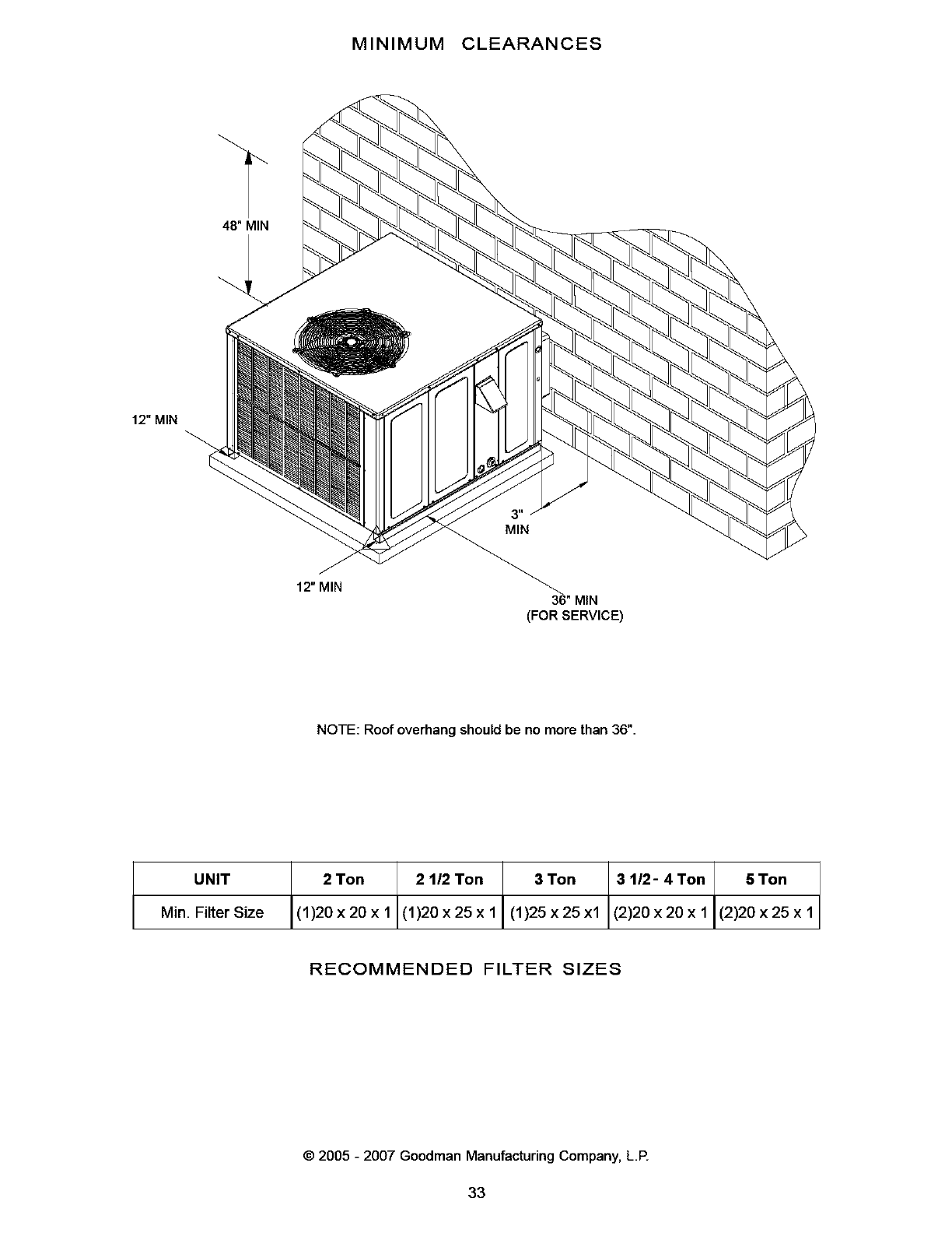
MINIMUM CLEARANCES
48" MIN
12" MIN
12" MIN 36" MIN
(FOR SERVICE)
NOTE: Roof overhang should be no more than 36".
UNIT 2 Ton 2 112 Ton 3 Ton 3 tl2- 4Ton 5 Ton
(1)20x20x1 (1)20x25xlJ(1)25x25x1 (2)20x20x1 (2)20x25x1Min. Filter Size
I
RECOMMENDED FILTER SIZES
©2005 - 2007 Goodman Manufacturing Company, L.P.
33
