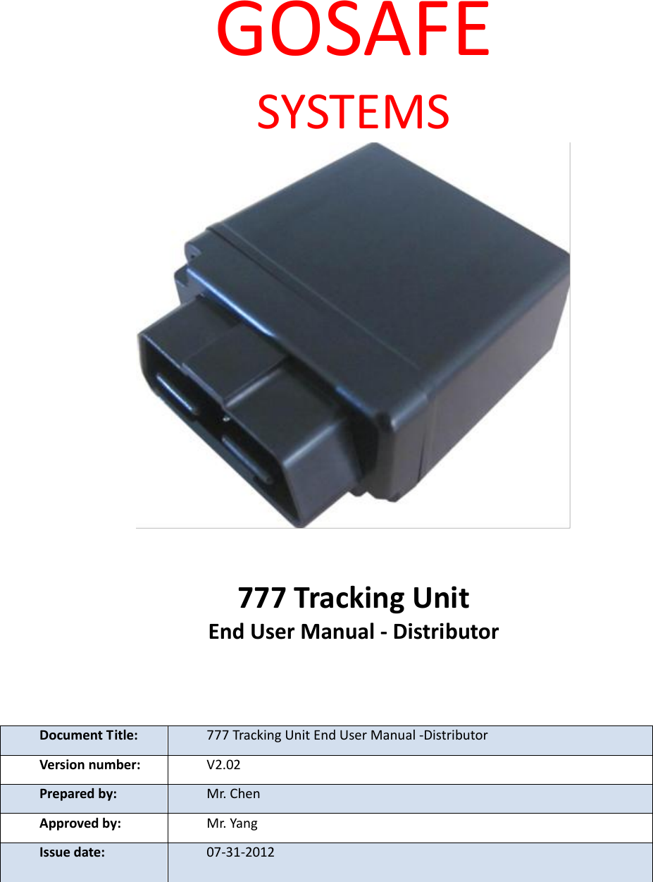
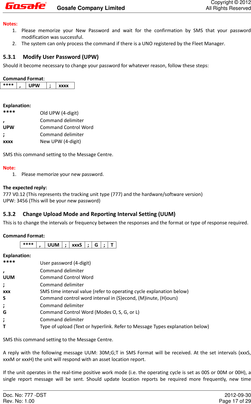
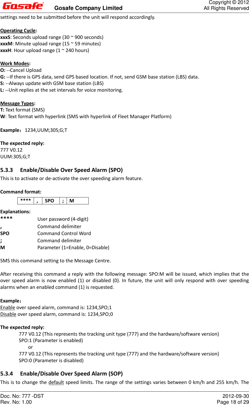
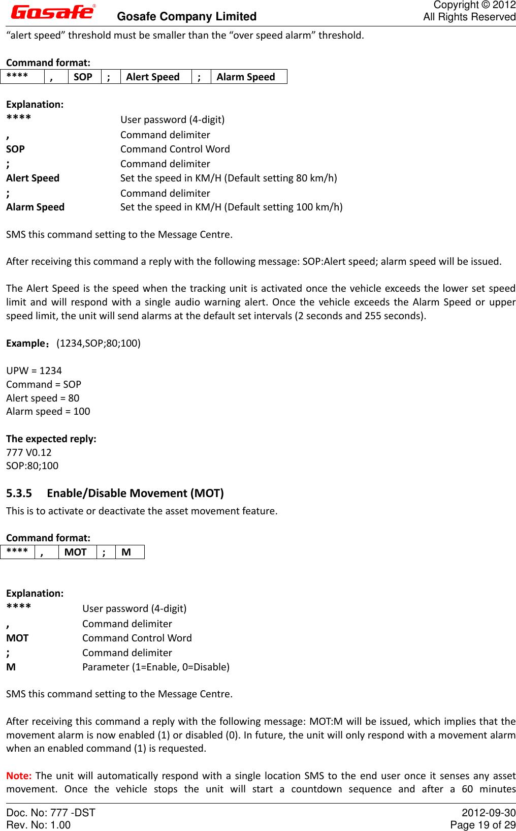
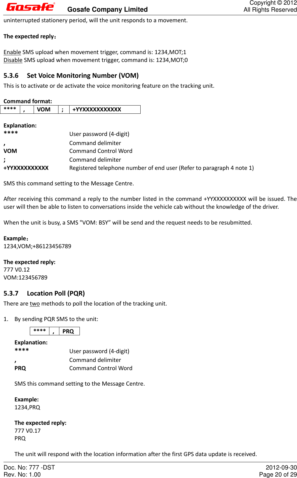
GOSAFE G-777-797 GPS Tracker User Manual Integrated Logistic Support Plan for the ATS
Gosafe Company Limited GPS Tracker Integrated Logistic Support Plan for the ATS
UserManual.wiki
>
GOSAFE
>
G 777 797 User Manual
User Manual Rev1
Navigation menu
Upload a User Manual
Namespaces
Wiki Guide
HTML
PDF
Info
Views
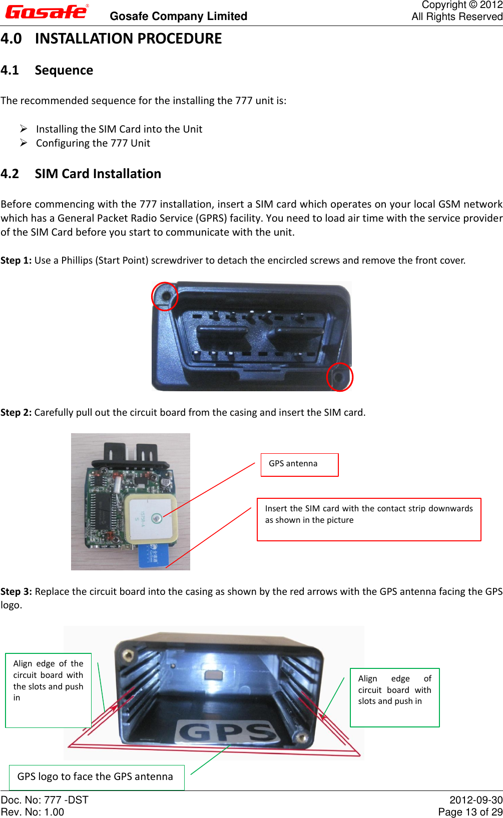
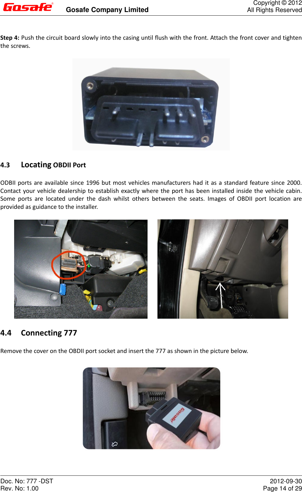
User Manual
Discussion / Help
Navigation