GROWATT NEW ENERGY TECHNOLOGY SHINE Data-Logger User Manual Shine pano
GROWATT NEW ENERGY TECHNOLOGY CO., LTD. Data-Logger Shine pano
users manual
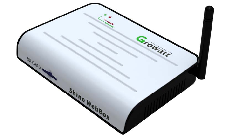
ShineWebBox
UserManual
2
Content
1Introduction...................................................................................................................................3
1.1Interface..............................................................................................................................3
1.2LEDStatusDisplay...............................................................................................................4
2ShineWebBoxInstallation..............................................................................................................5
2.1PackageList.................................................................................................................5
2.2ShineWebBoxhungvertically.....................................................................................6
2.3ShineWebBoxplacedonplane...................................................................................8
3OperationInstruction.....................................................................................................................8
3.1Connection..........................................................................................................................8
3.1.1NetworkDiagram.....................................................................................................8
3.1.2WiredCommunication.............................................................................................9
3.1.3WirelessCommunication.......................................................................................10
3.2ShineServerInstallation....................................................................................................11
3.3Login..................................................................................................................................14
3.4ServerSetting....................................................................................................................19
3.5TcpSetting.........................................................................................................................20
4.FAQ..............................................................................................................................................22
AppendixA......................................................................................................................................24
AppendixB......................................................................................................................................26
Contact............................................................................................................................................28
3
1Introduction
Shine WebBox is specially designed for solar power plant remote
monitoring. While supporting both wired and wireless communication, Shine
WebBoxcansimultaneouslymonitor, record and analyze inverter operating
parametersrealtimewithamaximumquantityof50.
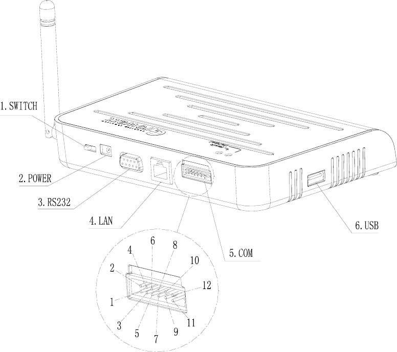
1.1Interface
4
Figure1‐1‐1
No. Name Description
1 Switch PowerSwitch,Turn
ON/OFFShineWebBox
2 Powersupplyinterface Supply power to Shine
WebBox
3 RS232interface Onlyfordebugginguse,
whendeveloping
4 LANinterface Connect Shine WebBox
withShineServerinlocal
areanetwork(LAN)
5
COM
See, of which 2.4 to RS485
lines ,Other used for active
and reactive power regulation
6 USBinterface Connect USB driver for
firmwareupdate
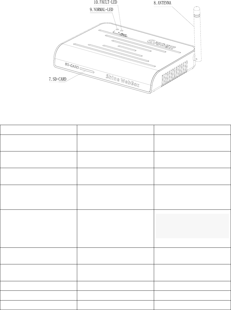
7 SD‐CARDsocket ConnectSD‐CARDfordata
storage
8 ANTENNA Receiveswirelesssignal
9 NORMAL‐LED Referto1.2
10 FAULT‐LED Referto1.2
Table1
1.2LEDStatusDisplay

5
Redlight Greenlight Meaning
● ● Initialization
○ · Searchinginverters
○ · Standby
○ ● Normaloperation
● ○ Planthasreporteda faultor
noSDcardinShineWebBox
Table2
● LEDON
○ LEDOFF
· LEDblinksslowly
· LEDblinksfast
2ShineWebBoxInstallation
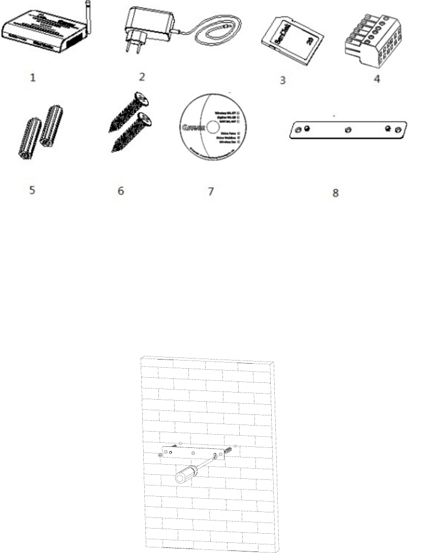
2.1PackageList
OpenShineWebBoxpackage,youwillseethefollowingitems.
Position DesignationQuantity
1 ShineWebBox1
2 5Vpoweradapter1
3 2GSDcard1
4 RS485terminal1
5 Plasticcolumn2
6 M3.5*20screws2
7 Usermanual1
8 Bracket1
Table3
6
Figure2‐1‐1
2.2ShineWebBoxhungvertically
Operationstepsasfollowing
(1)Installthebrackettotheverticalplane.
Figure2‐2‐1
(2)InstallShineWebBoxtothebracket.

7
Figure2‐2‐2
(3) After finishing installing, the Shine WebBox will be hung like the following
figure.
Figure2‐2‐3
(4)Connect RS485 cable which is connected to inverters(Refer to 3.1.1) or
connectwirelessmodulestoinverters(Referto3.1.2).
(5)Connectnetworkcable.
(6)InsertSDcardbeforeturningonShineWebBox(ifnot,SDcardwillnotbe
read).
(7)Connectpoweradapter.
(8)Turnonpowerswitch.
8
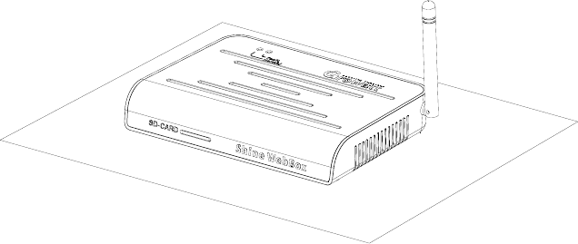
2.3ShineWebBoxplacedonplane
Operationstepsasfollowing
(1)PutShineWebBoxonplane,asfollowingfigure.
Figure2‐3‐1
(2)Connect RS485 cable which is connected to inverters(Refer to 3.1.1) or
connectwirelessmodulestoinverters(Referto3.1.2).
(3)Connectnetworkcable.
(4)InsertSDcardbeforeturningonShineWebBox(ifnot,SDcardwillnotbe
read).
(5)Connectpoweradapter.
(6)Turnonpowerswitch.
3OperationInstruction
3.1Connection
ShineWebBoxsupportsbothwiredandwirelesscommunication.
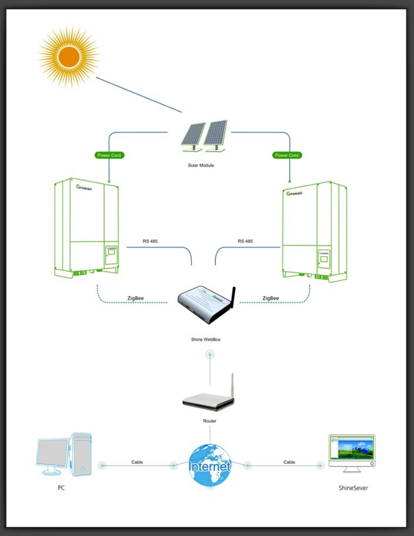
3.1.1NetworkDiagram
ThefollowingfigureisNetworkDiagram,itshowshowtoconnectinverter,ShineWebBox,router
andPCtogether(Foreachinverter,onewayneedtobeselected,RS485connectionorZigBee,
andtheycannotexistatthesametime.)
9
Figure3‐1‐5
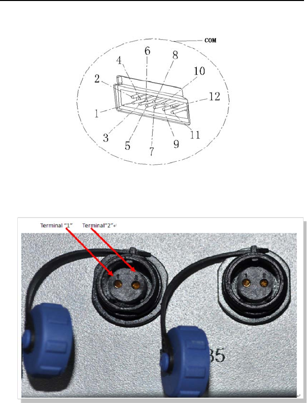
3.1.2WiredCommunication
ShineWebBoxcanmonitor32invertersbyRS485simultaneously.
Pleaseconnectthe ShineWebBoxand inverterbyRS485cableas following
figures.
10
ShineWebBox Inverter
2 Terminal2
4 Terminal1
Figure311
Figure312
Communicationaddresssetting
Set each inverter communication address to be fixed address in sequence,
rangingfrom1to32.PleaserefertoAppendixA(communicationaddresssetting).
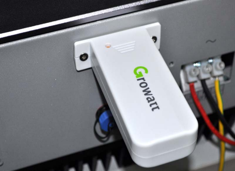
3.1.3WirelessCommunication
Connect one ZigBee transmitter to each inverter through RS232 interface,
andoneShineWebBoxcanmonitor30inverterssimultaneously.(Pleasereferto
wirelessadapterusermanualtoseetheinternalsettingofwirelessadapter)
11
Figure3‐1‐4
3.2ShineServerInstallation
Procedure
1.ContactGrowattforsoftware“ShineServer”.
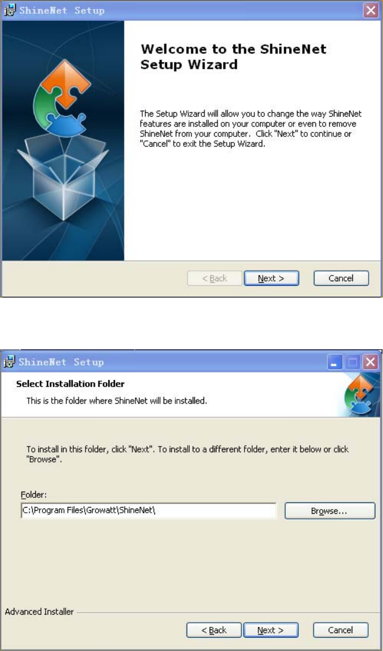
2. Double click the “ .exe“ file, then the following interface will appear as
figure3‐2‐1.
12
Figure3‐2‐1
3.Click next,thenshownasfollowingfigure3‐2‐2.
Figure3‐2‐2
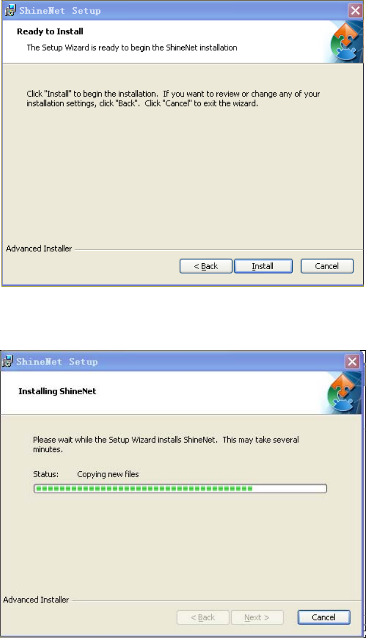
4.Clicknext,thenshownasfollowingfigure3‐2‐3.
13
Figure3‐2‐3
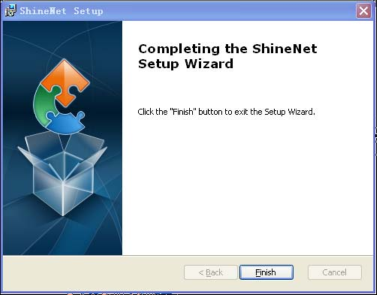
5.Clickinstall,thenshownasfollowingfigure3‐2‐4.
Figure3‐2‐4
14
6.Clickfinish,andinstallationfinishedasfigure3‐2‐5.
Figure3‐2‐5
3.3Login
1.ConnectShineWebBoxandtheserverwithShineServerinthesamelocal
areanetwork(LAN).
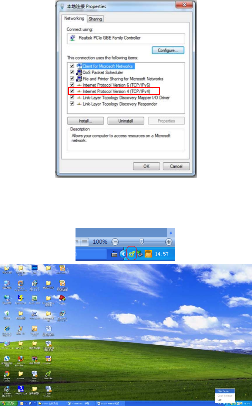
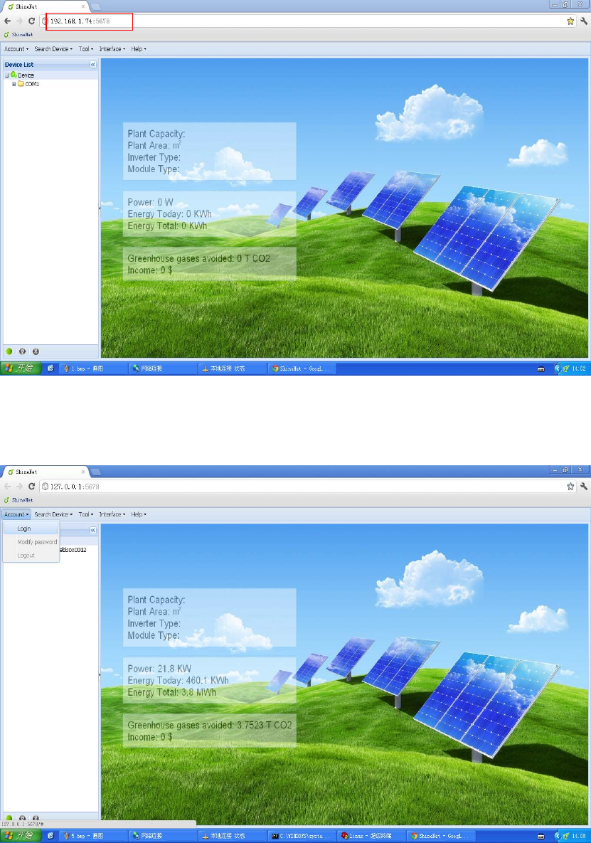
2.SetIPaddressoftheserverto192.168.1.74,asfigure3‐3‐1.
15
Figure3‐3‐1
3.RunShineServerasadministrator.ShineServericonwillappearon
systemtray.
Figure3‐3‐2

16
4.Rightclicktheicon,andselect“startserver”.
Figure3‐3‐3
5.Rightclicktheiconagainandselect“openinterface”;orinput
http://192.168.1.74:5678inthebrowser.
Note:PleaseuseChromebrowserforbetterperformance.
17
Figure3‐3‐4
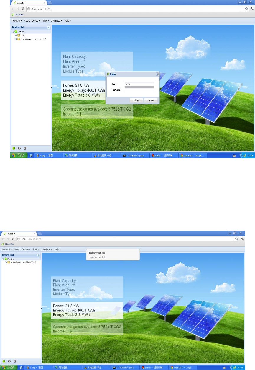
6.Click“Account”menuandselect“Login”.
Figure3‐3‐5
18
Figure3‐3‐6
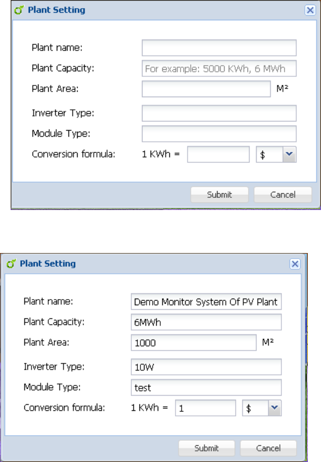
7.InputPassword(InitialPasswordis123456).
Note:Passwordcanbemodifiedafterloginsuccessfullybyclicking“Account”
andselecting“Modifypassword”.
Figure3‐3‐7
19
3.4ServerSetting
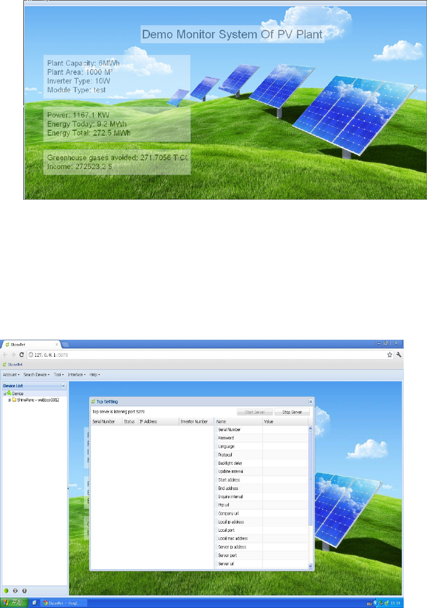
1. After login successfully, single click “Interface” then “Plant Setting”, a
followingpop‐upinterfacewillappearasfigure3‐4‐1.
Figure3‐4‐1
2.Entertheinfoyouneedinorder,taketheexampleoffigure3‐4‐2.
Figure3‐4‐2
3.Singleclick“Submit”,themaininterfacewilldisplayasfigure3‐4‐3.
20
Figure3‐4‐3
3.5TcpSetting
1.Singleclick“SearchDevice”then“Tcpsetting”,afollowingpop‐upinterface
willappearasfigure3‐5‐1.
Figure3‐5‐1
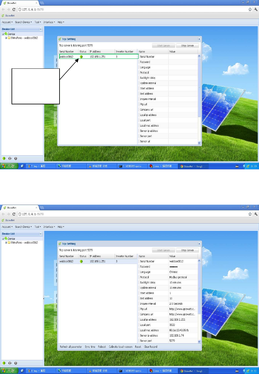
2.Singleclick“StartServer”,thenclickthelistontheleftsideinTcpSettingas
figure3‐5‐2.
21
Figure3‐5‐2
3.Singleclick ShineServertoconnectShineWebBox,thenyouwillsee
parameterinfoofcorresponding ShineWebBoxasfigure3‐5‐3.
Figure3‐5‐3
ShineServer
connected
ShineWebBox

22
4.FAQ
1.RS485&ZigBeecan’tsetupcommunication
Possiblecause
(1)TheCOMaddresssetininverterisnotfixedaddress.
(2)TheaddressrangeinsystemsettingofShineWebBoxisnotright.
(3)RS485cableisconnectedinawrongway.
(4)ZigBeemodulesaren’tinthesamenetworkID.
Solution
(1)SetCOMaddresstofixedaddress.
(2)ShineWebBoxinitialaddressrangemustincludeaddressesofallinverters.
(3)ConnectRS485cableinarightway.
(4)SetZigBeemodulesinthesamenetworkID.
2.ShineServerpagecan’tbeopened
Possiblecause
(1)“StartServer”atsystemtraydoesn’tstart.
(2)TheIPaddressorportyouvisitiswrong.
Solution
(1) Start“startServer”.
(2)Enter the right IP address and port(the default IP address is
192.168.1.74,port is 5678,so you need to enter
http://192.168.1.74:5678intobrowser).
3.ShineServercan’treceivedata
Possiblecause
(1)Localareanetwork(LAN)connectionof ShineWebBoxisnotgood.
(2)TheIPaddressoftheserverisnotmatchedwiththeIPaddressofShine
WebBox.
(3)“StartServer”in“Tcpsetting”ofShineServerisn’topened.
Solution
(1)Makethelocalareanetwork(LAN)betweenShineWebBoxand
ShineServerconnectwell.
(2)SetShineWebBoxaddresstoShineServerhostaddress.
(3)Click“StartServer”in“Tcpsetting”of ShineServer,thendovisit.
4.ShineWebBoxupgrading
(1)Shine WebBox adopts U disk to upgrade through USB interface, when
insert the U disk to USB interface, Shine WebBox will automatically
checkifthereisupgradepackageinit.
(2)Ifanupgradepackageisdetected,itwillupgradeautomatically.
(3)After upgrading successfully, the buzzer will ring twice, ShineWebBox
23
willrestartautomatically.PleaseremembertotakeouttheUdisk,ifnot,
ShineWebBoxwillupgraderepeatedly.
5.Modifyportnumber
Find ShineServer installation path (the default is C:\Program
Files\Growatt\ShineServer),openShineServerfolder,thenconfigfolder(openas
notepad),thedefaultis“server.port=5678”,theport“5678”canbemodifiedtothe
portyouwant.

24
AppendixA
Communication address setting
1. Growatt single phase inverter
Applies to Growatt1500TL, Growatt2000TL, Growatt3000TL, Growatt4400TL,
Growatt5000TL, Sungold1500TL, Sungold2000TL, Sungold3000TL, Sungold5000TL,
Growatt3600MTL, Growatt4200MTL, Growatt5000MTL
Growatt1500TL-US, Growatt2000TL-US, Growatt3000TL-US, Growatt4400TL-US,
Growatt5000TL-US, Growatt3600MTL-US, Growatt4200MTL-US, Growatt5000MTL-US.
1. Singleknockontheinverterpaneluntilitshows:COMAddress.Pleasereferto
thebelowpicture.
(GrowattinverterCOMAddresswassettobeMoveasdefault)
2. DoubleknockontheinverterpanelandtheCOMAddresswillbechangedto
be fixedCOM Address (such as 01, 02 ……). The COM Address will be saved
aftertheLCDturnsdark.
IfyouwanttosettheCOMAddresstobeMOVEagain,doubleknock on the
inverterpanelwhentheLCDdisplayshowstheCOMAddress.
Note:MaximumCOMAddressis:255.Address126isforbroadcasting;don’tsettheCOM
Addresstobe126.
2. Growatt three phase inverter
Growatt10000UE, Growatt12000UE, Growatt18000UE, Growatt20000UE
Growatt10000-US, Growatt12000-US, Growatt18000-US, Growatt20000-US
25
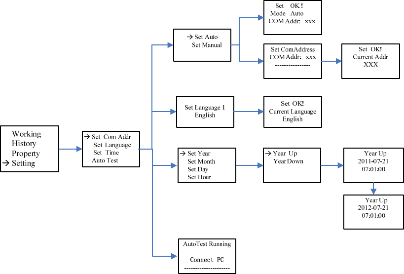
Please refer to the below graph:
Info:
Tripleknockcangetbacktothepreviouslevelmenu,doubleknockcanenterinto
thenextlevelmenu,andsingleknockcanmovethepointer.
z SetCOMAddresstobeMOVE(orauto)
Setting‐>SetCOMaddr‐>SetCOMAuto,thendoubleknockonthepanelandLCD
screenwilldisplay“SetOK,ModeAuto,COMaddr:xxx”.
z SetCOMaddresstobefixed
Setting‐>SetCOMaddr‐>SetCOMManual,thendoubleknockonthepaneland
enter the COM address setting mode. Single knock on the panel can change the
valueofCOMAddressanddoubleknockwillsavechanges,thenLCDscreenwill
display“SetAddrOK!CurrentAddrXXX”.
Note:MaximumCOMAddressis:255.Address126isforbroadcasting;don’tsettheCOM
Addresstobe126.
26
AppendixB
Shine WebBox Factory Warranty
For Shine WebBox, you receive a Growatt factory warranty valid for 5 years from the date
of purchase, and no more than 5 year and a half year from the date of delivery from
Growatt New Energy Co. Ltd.
This warranty coversrepairorreplacementpartscostsincurredduringtheagreed
period
Excluded from warranty are damages due to:
• Breaking the product seal (opening the casing)
• Transport damage
• Incorrect installation or commissioning
• Failure to observe the user manual, the installation guide, and the maintenance
regulations
• Unauthorized Modifications, changes, or attempted repairs
• Incorrect use or inappropriate operation
• Failure to observe the applicable safety regulations
• Force majeure (e.g., lightning, overvoltage, storm, fire)
Further‐reachingoradditionalclaimsduetodirectorindirectdamage,especially
claimsforcompensationfordamagesduetolossofprofitsorduetocostsarising
fromdisassemblyandmounting,areexcludedifnolegallymandatoryliability
applies.
Warranty condition
If a device becomes defective during the agreed Growatt factory warranty period and provided
that it will not be impossible or unreasonable, the device will be, as selected by Growatt,
• repaired by Growatt, or
• repaired on-site, or
• exchanged for a replacement device of equivalent value according to model and age.
In the latter case, the remainder of the warranty entitlement will be transferred to the
replacement device. In this case, you do not receive a new certificate since your entitlement is
documented at Growatt.
Fordeterminationofwarrantyeligibility,youmayneedtopresentacopyofthe
purchasereceipt,oracopyoftheExtensionWarrantyCard,andtheserialnumberof
theunit.Otherwise,Growattisentitledtorefusetoprovidewarrantyservices.

27
Extension warranty
Growattprovides5yearsextensionwarrantyforShineWebBox.
Forwarrantyextensiondetailsorwarrantyextensionpleasecontact
service@ginverter.com,customersneedtofillinawarrantyextensioncardandsend
toGrowattbyemailorfax,wewillstampcompanysealtovaliditandthensendback
tocustomers.
28
Contact
IfyouhaveanyinquiryortechnicalproblemsconcerningShineWebBox,contactyourinstalleror
Growatt.
GrowattNewEnergyCo.,Ltd
XichengIndustrialZone,Bao'anDistrict,Shenzhen,51800,China.
Tel :+86(0)75527471942
Fax:+86(0)75527491460
Email:service@ginverter.com
Website:www.ginverter.com
29
FCCStatement
Thisdevicecomplieswithpart15oftheUSFCCRulesandRegulations.Operationissubjecttothe
followingtwoconditions:(1)Thisdevicemaynotcauseharmfulinterference,and(2)Thisdevice
mustacceptanyinterferencereceived,includinginterferencethatmaycauseundesired
operation.
ThisequipmenthasbeentestedandfoundtocomplywiththelimitsforaClassBdigitaldevice,
pursuanttoPart15oftheUSFCCRules.Theselimitsaredesignedtoprovidereasonable
protectionagainstharmfulinterferenceinaresidentialinstallation.Thisequipmentgenerates,
uses,andcanradiateradio‐frequencyenergyand,ifnotinstalledandusedinaccordancewith
theseinstructions,maycauseharmfulinterferencetoradiocommunications.However,thereis
noguaranteethatinterferencewillnotoccurinaparticularinstallation.Ifthisequipmentdoes
causeharmfulinterferencetoradioortelevisionreception,whichcanbedeterminedbyturning
theequipmentonandoff,theuserisencouragedtocorrecttheinterferencebyoneormoreof
thefollowingmeasures:
•Reorientorrelocatethereceivingantenna;
•Increasetheseparationbetweentheaffectedequipmentandtheunit;
•Connecttheaffectedequipmenttoapoweroutletonadifferentcircuitfromthatwhichthe
receiverisconnectedto;
•Consultthedealerand/orexperiencedradio/TVtechnicianforhelp.
FCCRFRadiationExposureStatement
ThisequipmentcomplieswithFCCRFradiationexposurelimitssetforthforanuncontrolled
environment.Thisequipmentshouldbeinstalledandoperatedwithaminimumdistanceof20
centimetersbetweentheradiatorandyourbody.
Note:ThemanufacturerisnotresponsibleforanyradioorTVinterferencecausedby
unauthorizedmodificationstothisequipment.Suchmodificationscouldvoidtheuser’sauthority
tooperatetheequipment.