GS Instech GRS-1923R-SPR RF Repeater User Manual ATT E
GS Instruments Co., Ltd. RF Repeater ATT E
User manual

FCC ID : U88-GRS-1923R-SPR
HCT CO., LTD.
SAN 136-1, AMI-RI, BUBAL-EUP, ICHEON-SI, KYOUNGKI-DO, 467-701, KOREA
TEL:+82 31 639 8517 FAX:+82 31 639 8525 www.hct.co.kr
Report No. : HCTR1007FR27 1/1
ATTACHMENT E.
- USER MANUAL -

Sprint User Manual
3G Indoor Repeater
1
/
23
3G Indoor Repeater
GRS-1923R-SPR
User Manual
May, 2010
Version 0.1

Sprint User Manual
3G Indoor Repeater
2
/
23
- INDEX -
1. SUMMARY................................................................................... 3
2. SYSTEM CONFIGURATION ......................................................... 4
2.1 GRS-1923R-SPR Service Organization.......................................................4
2.2 System Design and Operation....................................................................5
3. SPECIFICATIONS ..................................................................... 11
3.1 System Specifications(Applicable to both Uplink & Downlink)................11
3.2 Electrical and Environmental Specifications............................................12
3.3 Functions .................................................................................................12
4. SET UP...................................................................................... 15
4.1 System Set up..........................................................................................15
4.2 Troubleshooting.......................................................................................19

Sprint User Manual
3G Indoor Repeater
3
/
23
1. SUMMARY
GRS-1923R-SPR is an Digital RF repeater, which improves PCS network.
GRS-1923R-SPR receives RF signal from BTS and transmits it to the blanked and shadowed area,
thus providing and improving voice and image data services. GRS-1923R-SPR’s goal is to
support BTS’s functions proportionately.
GRS-1923R-SPR communicates with BTS wirelessly, thus saving additional costs for its
maintenance.
GRS-1923R-SPR consists of RF/IF part module, Digital Filter module, and I/O & Control module
divisions, which are supplied with Alarm LED, thus providing quick and easy maintenance and
troubleshooting of the repeater.
This manual describes in general structure of GRS-1923R-SPR, its application, maintenance and
troubleshooting, installation and operation etc.
Abbreviation
PCS : Personal Communication System
RF: Radio Frequency
BTS: Base Transceiver Station
IF: Intermediate Frequency
I/O : Input/Output
Sprint User Manual
3G Indoor Repeater
4
/
23
2. System Configuration
2.1 GRS-1923R-SPR Service Organization
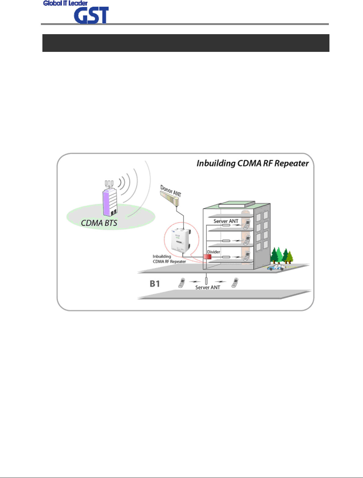
GRS-1923R-SPR decreases blanked and shadowed areas and extends cell coverage by re-trans
mitting signal. The signal is received from BTS via Antenna directly, thus excluding additional ex
penses for signal transmission (like cabling). Service organization of CDMA In-building RF repeat
er is shown at the picture below. Donor Antenna is directed to BTS, and being divided at Servic
e Antennas are installed in the building and parking place. Pass Loss should be taken into consi
deration while dividing and cabling.
<Pic.1> US PCS 1900 Service Organization
Sprint User Manual
3G Indoor Repeater
5
/
23
2.2 System Design and Operation
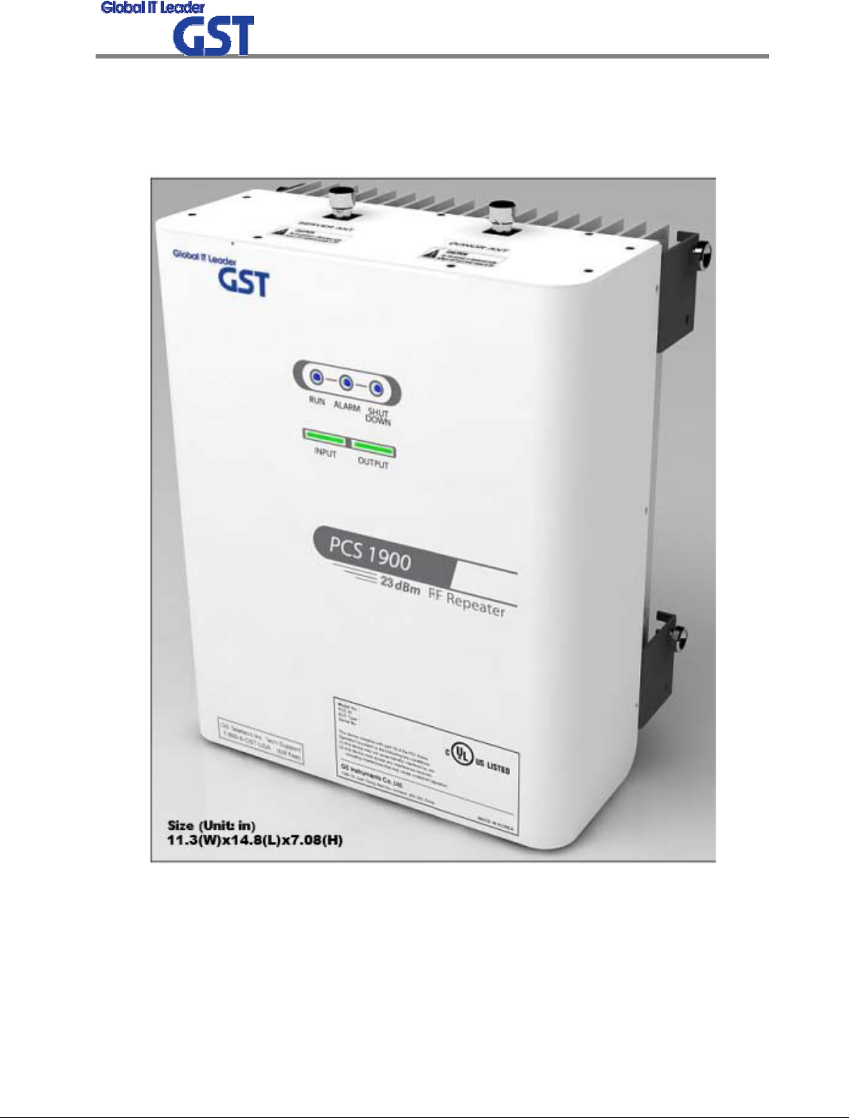
2.2.1 System Design
<Pic.2> GRS-1923R-SPR Repeater
Sprint User Manual
3G Indoor Repeater
6
/
23
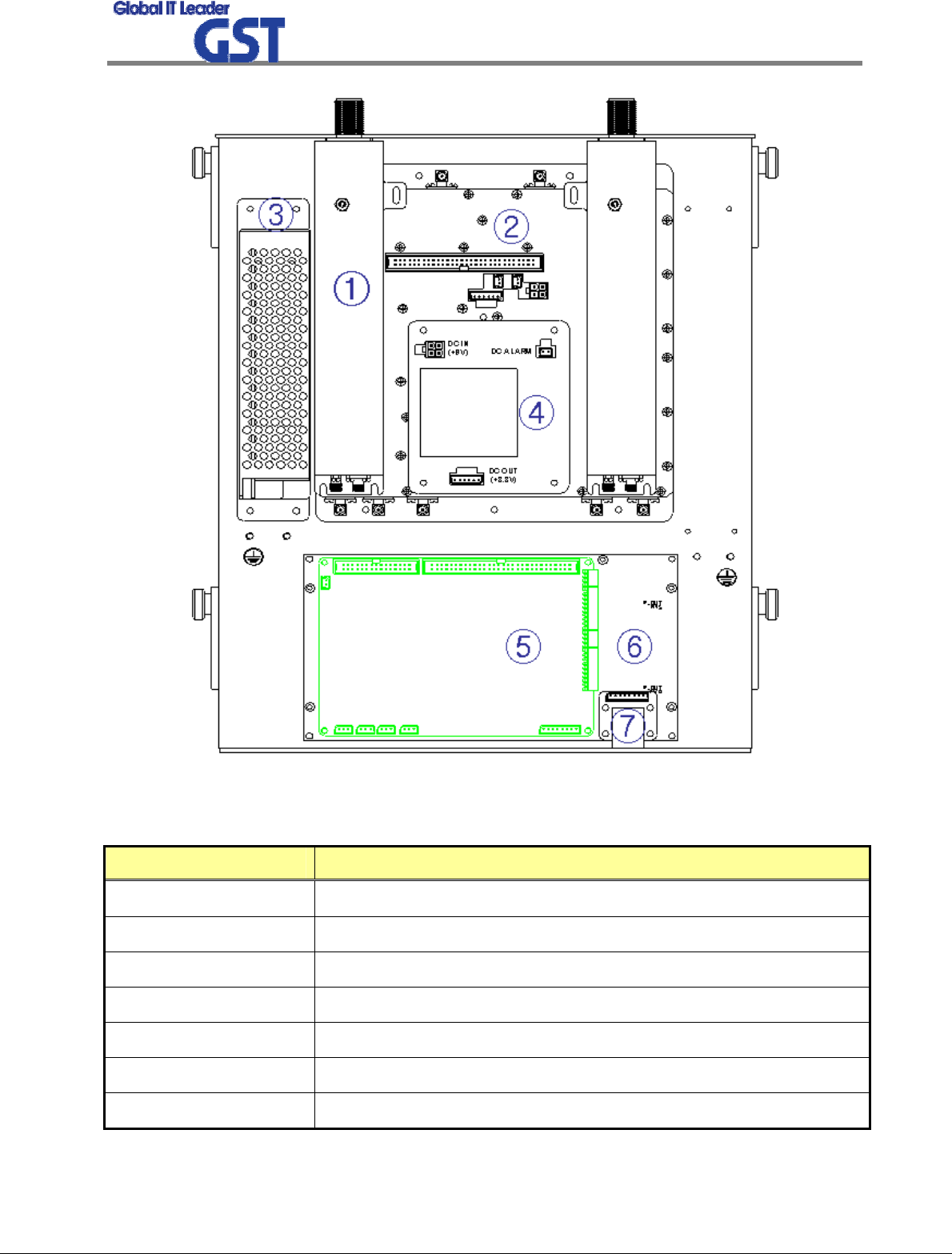
<Pic.3> Internal Design
NO DESCRIPTION
① CAVITY FILTER - (Frequency Filtering)
② CONVERTER MODULE - (Frequency Conversion)
③ PSU MODULE(RS-100-9) - (Converter, LED, NMS Power Supply)
④ I/O Board - (Input/Output Board)
⑤ NMS BOARD - (System Control Board)
⑥ DIGITAL FILTER - (Digital Filtering)
⑦ ETHERNET BOARD - (Web UI Board)
Sprint User Manual
3G Indoor Repeater
7
/
23
①②
③
④⑤⑥
①②
③
④⑤⑥
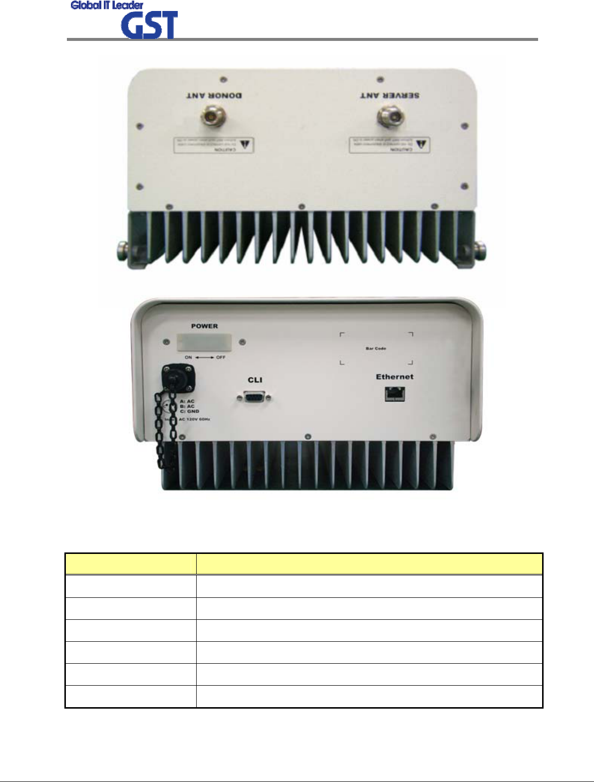
<Pic.4> Outside Port Design
NO DESCRIPTION
① DONOR ANT PORT
② SERVER ANT PORT
③ POWER SWITCH PORT
④ AC POWER PORT
⑤ CLI MONITOR PORT
⑥ ETHERNET PORT
Sprint User Manual
3G Indoor Repeater
8
/
23
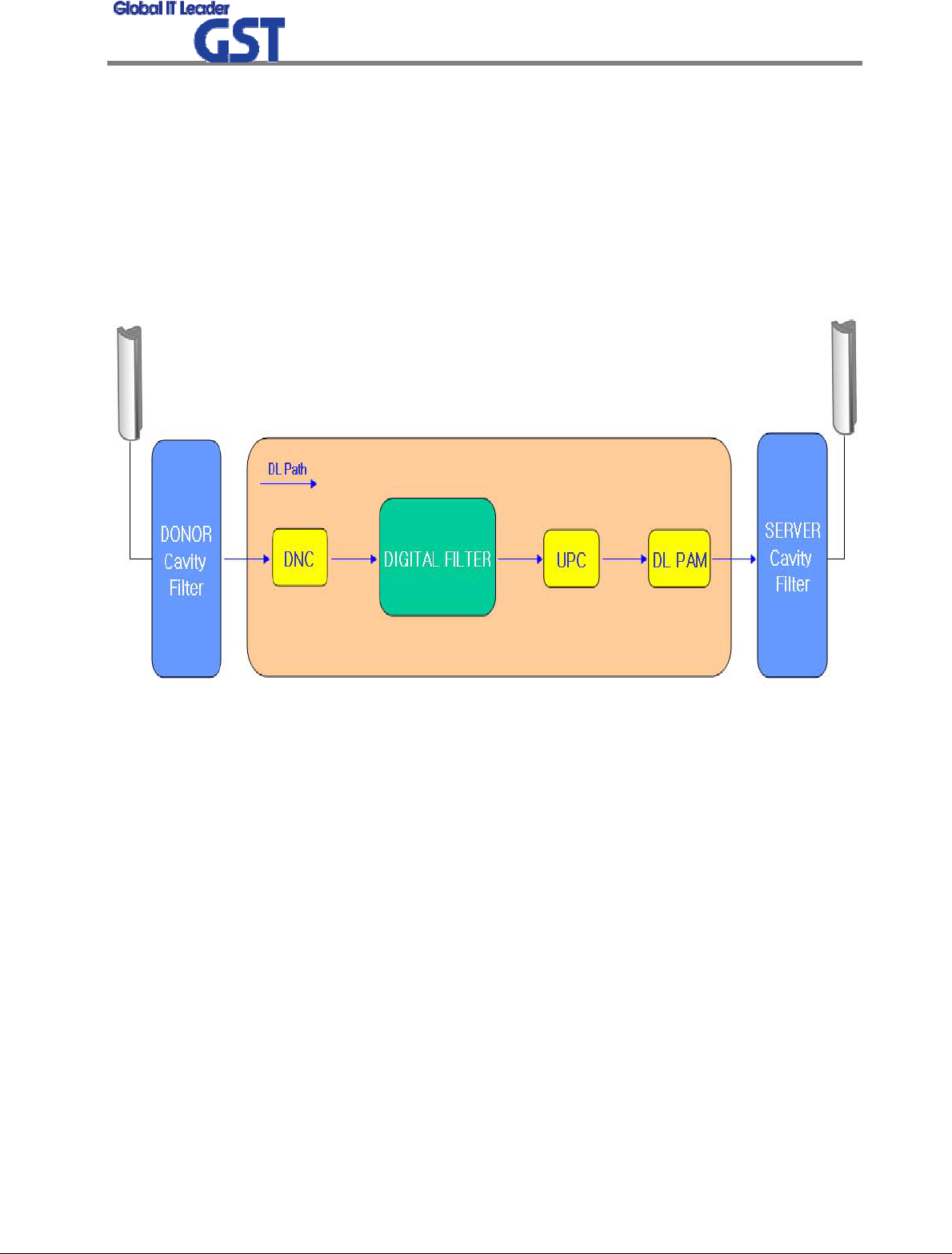
2.2.2 Downlink Path
Downlink and Uplink Gain Budgets have similar structure.
In case of Downlink Path, RF signal is received from Donor Antenna, and through FWD
division, then the signal is transferred to IF division, where desirable Band is selected by Digital
Filter. Selected Band is transferred to RF division again, and through FWD PAM, after that the
signal is transmitted to User through Server Antenna.
Two attenuators use for AGC compensation. AGC attenuation range is 40dB.
<Pic.5> Downlink Block Diagram
Sprint User Manual
3G Indoor Repeater
9
/
23
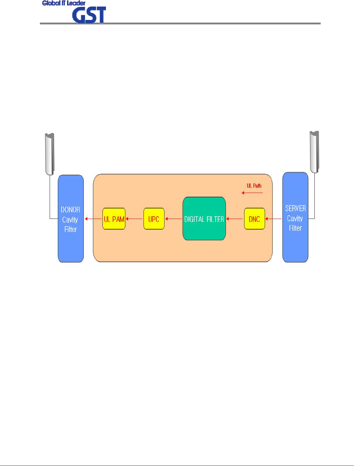
2.2.3 Uplink Path
Uplink Path is similar in structure to Downlink Path.
In case of Uplink Path, RF signal is received from Server Antenna, and through RVS division,
then the signal is transferred to IF division, where desirable Band is selected by Digital Filter.
Selected Band is transferred to RF division again, and through RVS PAM, after that the signal is
transmitted to BTS through Donor Antenna.
Two attenuators use for ALC compensation. ALC attenuation range is 40dB.
<Pic.6> Uplink Block Diagram
Sprint User Manual
3G Indoor Repeater
10
/
23
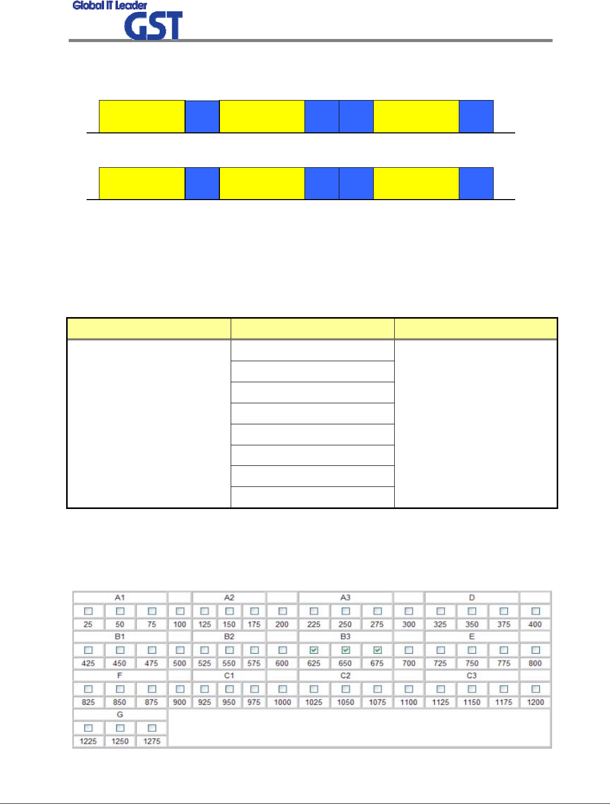
2.2.4 US PCS Frequency Selection
1930
AB CDEF G
1945 1950 1965 1970 1975 1990 1995
< Forward Band Structure >
f (MHz)
1930
AB CDEF G
1945 1950 1965 1970 1975 1990 1995
< Forward Band Structure >
f (MHz)
1850
AB CDEF G
1865 1870 1885 1890 1895 1910 1915 f (MHz)
< Reverse Band Structure >
1850
AB CDEF G
1865 1870 1885 1890 1895 1910 1915 f (MHz)
< Reverse Band Structure >
<Pic.7> 1900MHz PCS Band Structure
GRS-1923R-SPR has 5MHz, 10MHz, 15MHz, 20MHz Paths in IF division, so any of these bandwid
ths can be chosen for providing service.
ITEM BANDWIDTH NOTE
5MHz
10MHz
15MHz
20MHz
5MHz + 5MHz
5MHz + 5MHz + 5MHz
10MHz + 5MHz
Band Select
15MHz + 5MHz
Any of these bandwidths from
A to G can be chosen
Also, by adding Channel Select Function, it enables users to select bands sophisticatedly. Each b
and has 1.25MHz Bandwidth and if users select all the 15 bands, GRS-1923R-SPR can serve 18.
75MHz bandwidth to users.
Sprint User Manual
3G Indoor Repeater
11
/
23
3. SPECIFICATIONS
3.1 System Specifications(Applicable to both Uplink & Downlink)
ITEM SPECIFICATION REMARK
Transmit Power 23dBm ± 2.0dBm
Downlink 1930MHz ~ 1995MHz
Frequency
Range Uplink 1850MHz ~ 1915MHz
Gain Range 42dB ~ 82dB DL/UL both
Roll Off ≥ 50dBc @ F(edge)±1MHz
VSWR 1.5 : 1
Delay 8us
@
Fc±885kHz
≥ 45dBc marker to marker 29dB
In Band
Spurious
Emission @
Fc±1.98MHz
≥ -52dBc marker to marker 36dB
OUT Band Spurious
Emission < -13dBm
Flatness 3dB
5MHz
5+5MHz or 10MHz
5+5+5MHz or 10+5MHz or 15MHz
Band Select
15+5MHz or 20MHz
Non-contiguous Band
(Maximum 3-band)
Adding Channel Select
Function
Noise Figure 5dB @ Max Gain
12dB @ Min Gain
ALC Range 40dB, 1dB step
Frequency Stability ±0.05ppm
Waveform Quality Factor > 0.912
Output Power Variation
over Temperature ±2.0dB
Sprint User Manual
3G Indoor Repeater
12
/
23
3.2 Electrical and Environmental Specifications
ITEM SPECIFICATION REMARK
Power & Consumption 100 ~ 240 VAC,60Hz
Connector Type N-type female
Size 289X385X180
Weight max 40 lbs
Reliability, MTBF 100,000 hours
Enclosure NEMA4
Operating Temperature -10℃ ~ +50℃
Rel. Humidity 0% ~ 90%
Industry Standards TIA-97, TIA-98, IS-98D,
IS-2000
Regulatory Approvals FCC, Part24 CDN-IC
Safety Approvals UL1950 or Equiv
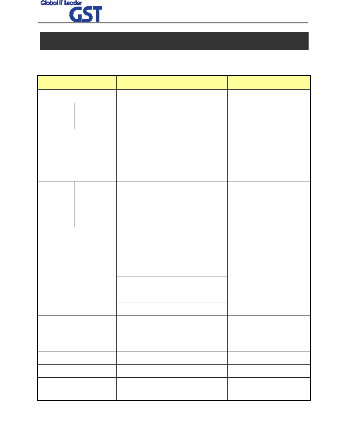
3.3 Functions
ITEM FUNCTIONS
Gain Control • Adjustable DL and UL Gain range 42~82dB
• Display default Gain and current Gain function
AGC
(Auto Gain Control)
• It always operates in Downlink AGC ON status
• To maintain same Downlink output power despite flexible input signal
strength
• To add or subtract Attenuation level referring to AGC Power Limit level.
• Used with the Automatic Setup (Auto Gain Setting)
ALC
(Auto Level Control)
• To limit output power as far as default range
• Used for DAS configuration and when oscillation/isolation is a concern
• Automatic Gain decrement when output power of repeater is higher
than default level
• Automatic Gain recovery when output power of repeater is reduced
Sprint User Manual
3G Indoor Repeater
13
/
23
• Shutdown when output power is higher than default level in Minimum
Gain
• Automatic Recovery Algorithm conversion after Shutdown status
AGS
(Auto Gain Setting)
• Operate when User control (Only system initialize)
• Decrease attenuator value for 3dB from minimum gain
• In case of attenuator value is from 0dB to 3dB when AGS ended
- AGC on (DL)
- Gain balance on
- PAM on
- Shut down on
• In case of attenuator value is over 3dB when AGS ended
- AGC off (ALC on)
- Gain balance off
- PAM on
- Shutdown on
Gain Balance
• Downlink ATT is applied to Uplink during AGC state
• Setting and maintenance of output level
• Additional attenuation to ALC Level
Band Select • To select either 5MHz/10MHz/15MHz/20MHz
Power Monitoring
Function • Monitoring repeater’s output level
DL Input control • Monitoring Donor ANT input power of DL
Automatic Recovery • When repeater is shutdown, it periodically recovers output power of
repeater then monitors alarming
Security • Support HTTPS for Web Browser security
• User authentication through User ID and Password
Tem p era ture
Monitoring
• Monitoring temperature of repeater
• Maximum and minimum set up is possible
• Shutdown in over temperature
• Automatic recovery after temperature becomes normal (Hysteresis 10
degree)
Sprint User Manual
3G Indoor Repeater
14
/
23
VSWR Monitoring • Monitoring VSWR of Donor ANT Port (Every one and half minute)
• Reporting VSWR Alarm and Shutdown when the rate is 3.5:1
IP address report via
E-mail
• When in PPP reconnection, E-mail which includes HTML to connect to
newly assigned IP Address, reports to operator.
DHCP Client • Automatic IP assignment
DHCP Server • Server function for automatic IP assignment
Web GUI • Remote and local user browser support through Web Browser
SNMP Agent • NMS report via SNMPv2 Trap
LED Display
• LED displays power and operation status on front side of repeater
system
• Input and Output signal levels are verified by LED bars
Sprint User Manual
3G Indoor Repeater
15
/
23
4. SET UP
4.1 System Set up
4.1.1 Constitution (Based on 1 set)
PARAMETER ITEM QUANTITY
Major Accessory US PCS 23dBm case 1 EA
Additional Components
Main power input cable
Fixable screw
Mountable brackets
1 EA
1 SET
1 EA
User Manual Manual 1 EA
4.1.2 Notice
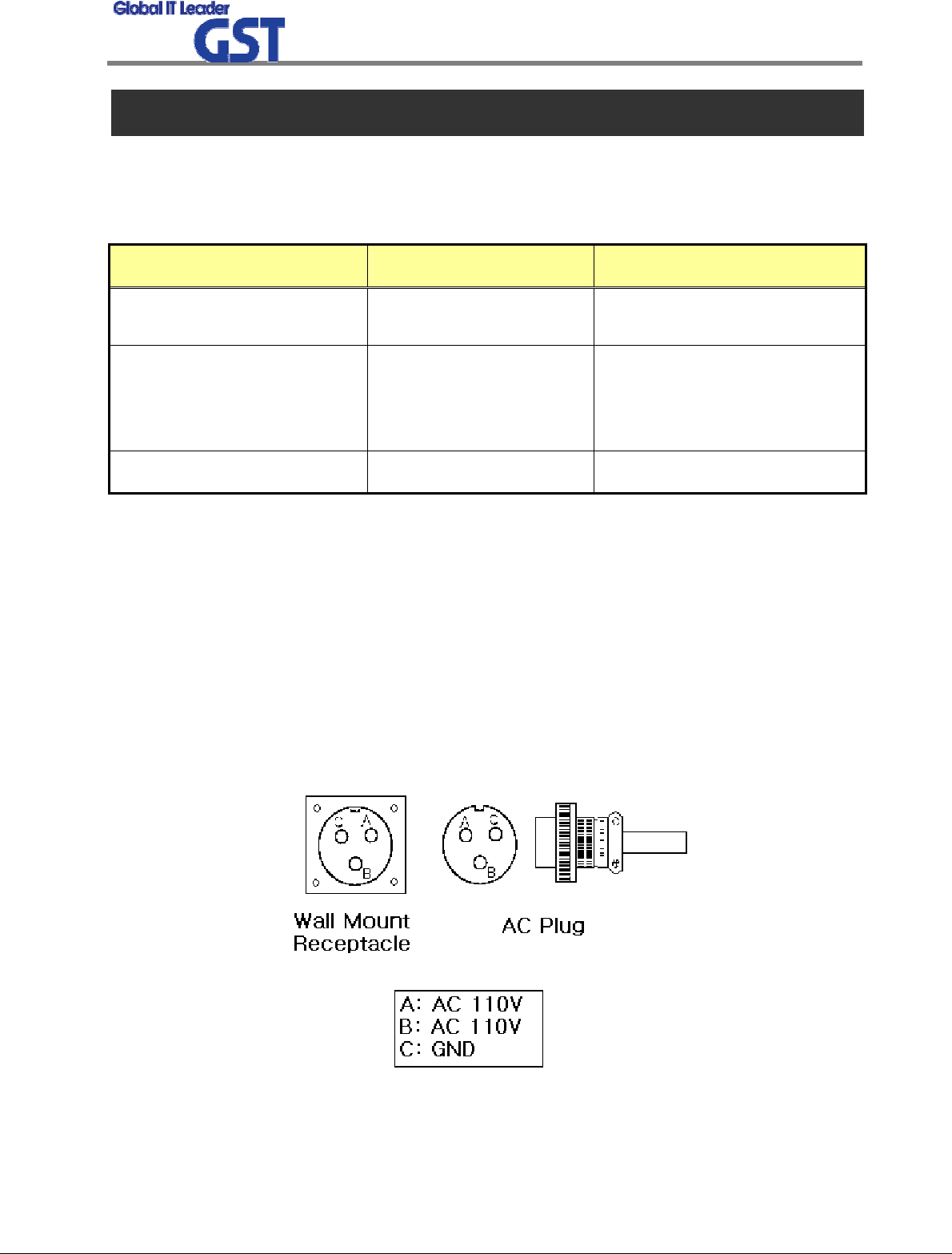
1) System Power check: Major electricity is AC110V, therefore please input electricity after
power verification.
2) Input condition optimization: DL input condition is -59 ~ -19dBm. User should verify
input condition of Donor ANT.
3) Isolation check between DONOR/SERVER ANT: Isolation condition of this equipment is
89dBc (Gain+7dB). User should check its condition before installation.
<Pic.8> MS 3100 A 10SL-3 (Wall Mount Receptacle) & MS3010 A 10SL-3(Plug)
Sprint User Manual
3G Indoor Repeater
16
/
23
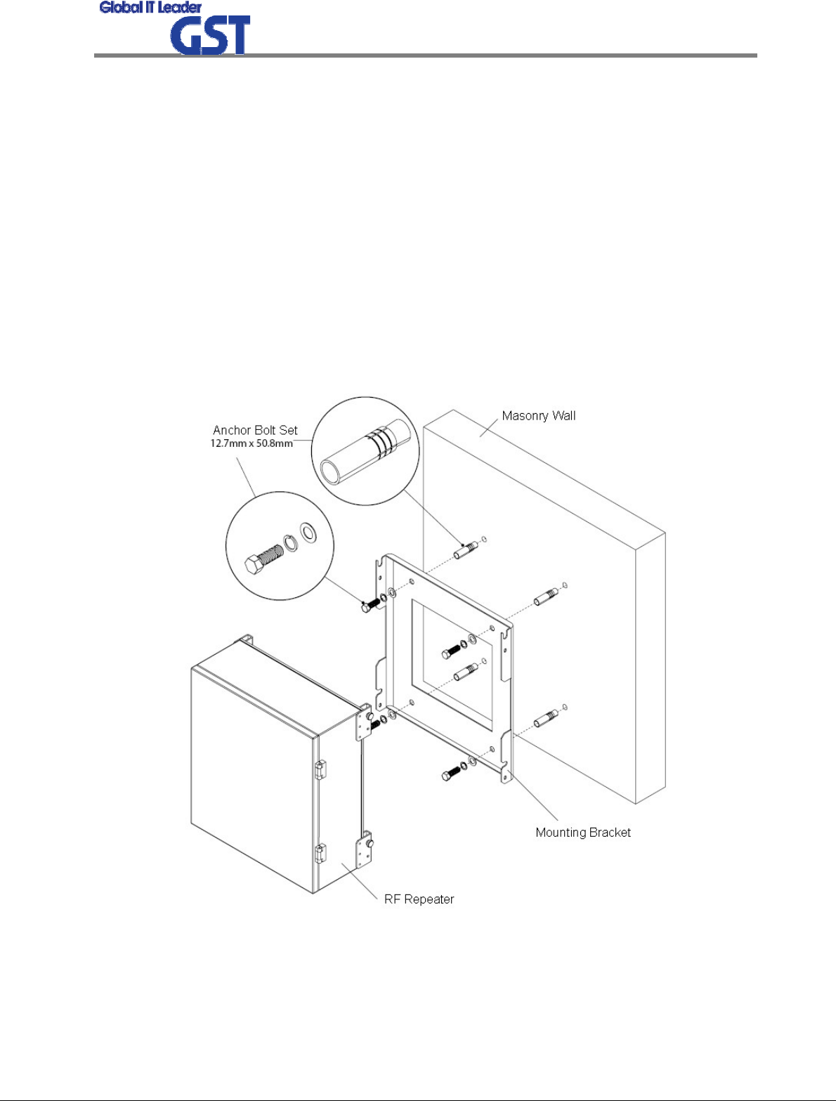
4.1.3 System Set up
1) This equipment is basically wall mountable installation.
2) Once aforementioned process is done, open for service get ready.
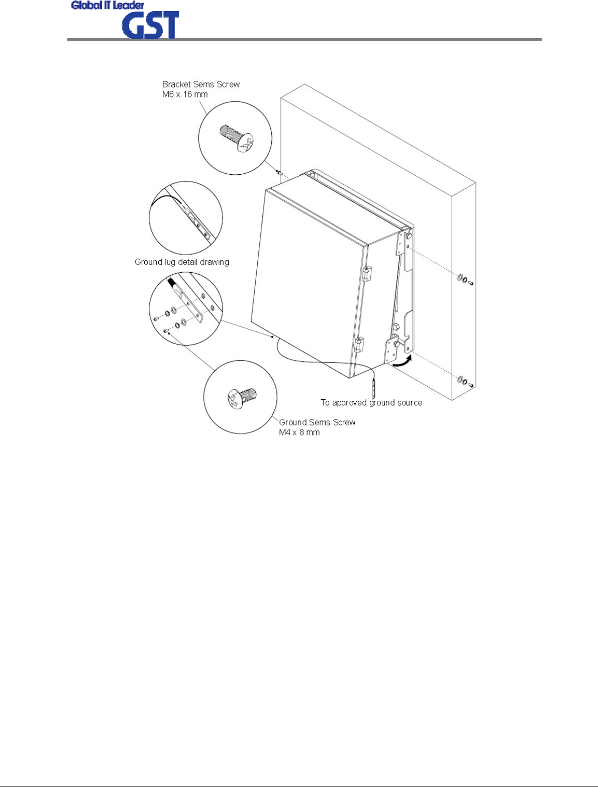
3) For grounding, there is a grounding terminal in main power supply side and the grounding
terminal on a site and unit should be connected same.
4) System installation work is basically performed more than two people and should be careful
for unexpected accident.
5) The socket-outlet shall be installed near the equipment and shall be easily accessible.
6) Round terminals located on the side of a 0.75 mm2 (18 AWG) or more wires Using
permanently connected to earth.
<Pic.9> Case Mounts - Step 1
Sprint User Manual
3G Indoor Repeater
17
/
23
<Pic.10> Case Mounts - Step 2
4.1.4 Open for Service
1) Check points before open
a. Verification of system installation status
- Electricity, In/out antenna, coaxial cable connection, equipment mounts status.
b. Verification of system accessories
- User should check whole necessary accessories.
c. Check receipt signal level
- User should check whether receipt environmental condition is in accordance with system
specification, so that system operation will be optimized.
2) Check points after open
a. Check by external LED
Sprint User Manual
3G Indoor Repeater
18
/
23
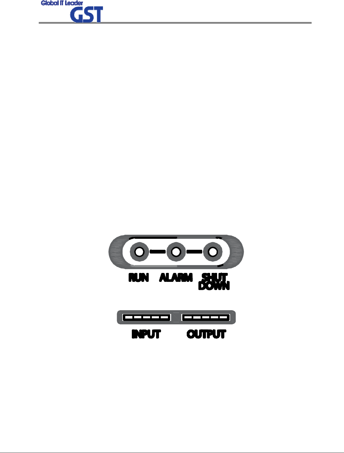
① RUN: Green light ON (Off: Green light off)
② ALARM: Green light in normal status, Red light in alarming
③ SHUT DOWN: Green light in normal status, Red light in Shutdown status
④ Number of LED bar on front side of repeater will show input power signal level
Less than -86dBm: LED 1 bar
-85dBm ~ -70dBm: LED 2 bar
-69dBm ~ -54dBm: LED 3 bar
-53dBm ~ -41dBm: LED 4 bar
More than -40dBm: LED 5 bar
⑤ Number of LED bar on front side of repeater will show output power signal level
Less than +5dBm: LED 1 bar
+6dBm ~ +10dBm: LED 2 bar
+11dBm ~ +15dBm: LED 3 bar
+16dBm ~ +20dBm: LED 4 bar
More than +21dBm: LED 5 bar
<Pic.11> Front LED
b. Verification of operation status
- User should verify following status with Output monitoring terminal, which is provided by
Spectrum Analyzer
- Output power generation status, system spurious emission characteristics.

Sprint User Manual
3G Indoor Repeater
19
/
23
c. Verification of signal quality and strength in service area
- User should verify signal strength and quality of in-service coverage area by using cell
phone or other measuring device.
d. Verification of upper-level NMS operation status
4.2 Troubleshooting
In case of abnormal operation, technician should diagnose abnormality via remote access or
directly connecting to repeater using Ethernet cable. If technician is required to conduct repairs
due to major alarm, repeater should first be powered off, and then technician should prepare
the proper measurement equipment before trying to fix the problem. In most cases of major
repairs, GST will simply replace the unit and conduct repairs at the appropriate facility.
4.2.1 Necessary Testing and Measuring Equipment
1) RF Power Meter: 10Watt Max, 50ohm
2) Signal Generator: 3GHz
3) Spectrum Analyzer: 3GHz
4) Multi-Meter
4.2.2 Notice
1) Troubleshooting should be performed by a trained technician.
2) Parts that seem to be not used should not be disassembled.
3) While troubleshooting, technician should use attenuator to check RF Signal output.
4.2.3 Simple Troubleshooting Method
1) Verify LED Status, both on external LED’s as well as internal module LED’s
- Normal operation: Green light on. Alarming: Red LED on.
2) Technician should check external and internal connectors to ensure that all connections are
tightly secure. These connectors should be cleaned regularly.
3) If technician thinks there is a serious problem, call after sales team for over-the-phone
technical support. 1-866-9-GST-USA (1-866-947-8872)
Sprint User Manual
3G Indoor Repeater
20
/
23
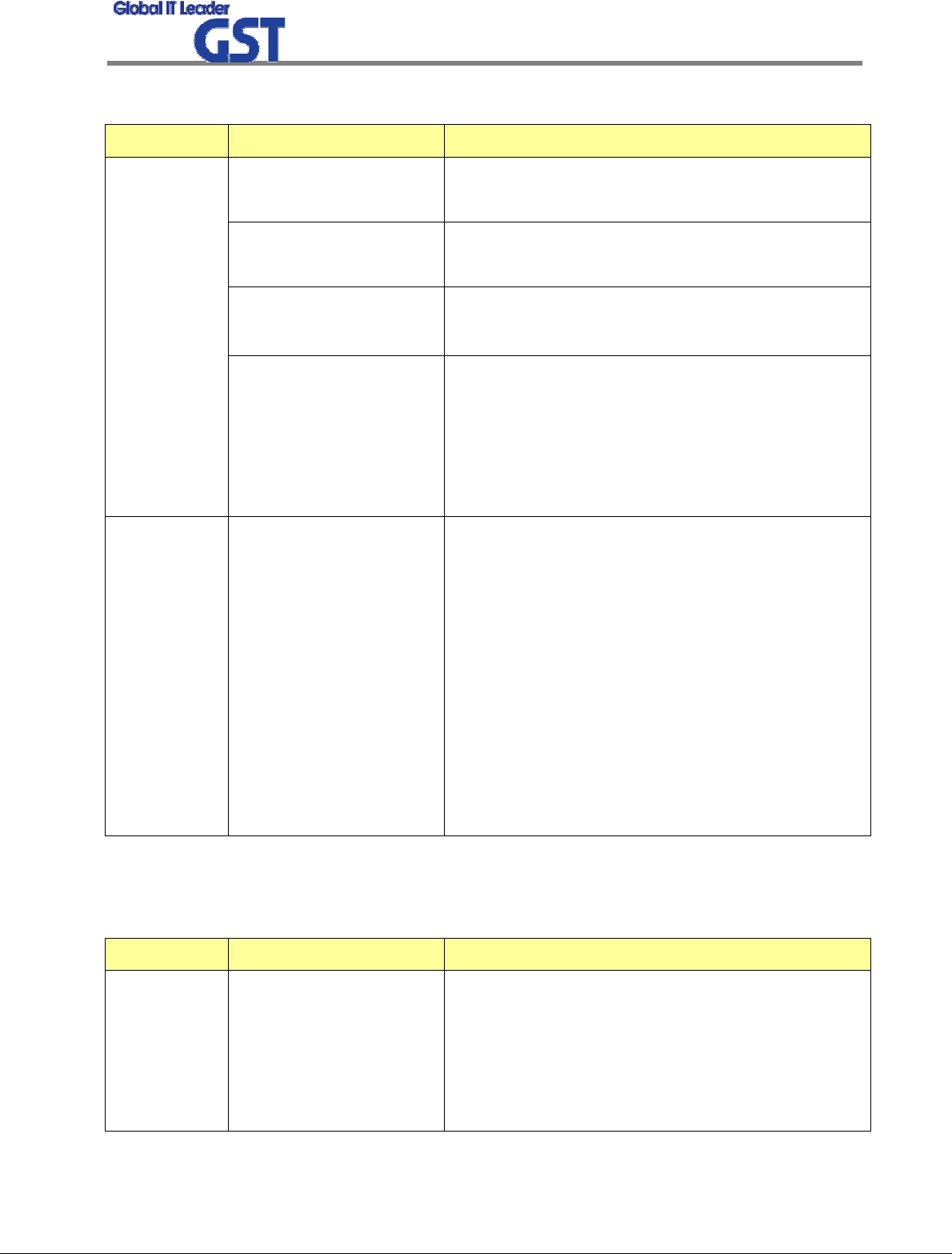
4.2.4 Troubleshooting Guide
Item Check Point Troubleshooting
System input power
range
-Downlink: -59dBm ~ -19dBm
-Uplink: -59dBm ~ -19dBm
System gain -Downlink: 42dB ~ 82dB
-Uplink: 42dB ~ 82dB
Output power at server
port
-Downlink: 23dBm ± 2dB
-Uplink: 23dBm ± 2dB
Check before
system
operation
Check points before open
for service
-Please check quantity of all accessories with
specification before you set up
-Fit cable length in accordance with field condition
-Set up 1900MHz CDMA Donor antenna to secure
Isolation. (More than 89dBc)
Check after
system
operation
Check points after open
for service
Check following status;
-Verify that the antennas are securely mounted
and pointed in the correct directions
-Connection status between antennas and RF cable
-Verify that the Repeater is securely mounted
-Proper AC power status
-Grounding status of electrical circuit
-Coaxial cable (RF) construction status
-Connectors and combiners connection status
-Cable connection status against leakage of water
4.2.5 Troubleshooting Guide Related to RF
Symptom Check Point Troubleshooting
When
repeater
does not
work
properly
Check electricity cord
connection status -Re-plug in Adapter cord

Sprint User Manual
3G Indoor Repeater
21
/
23
DL VSWR alarm
Please Check following status;
-Make sure Server Antenna Port is disconnected
-Please reset Adapter upon completing Alarm
troubleshooting
DL over-output alarm
-Make sure output power is operating normally
-Please Reset Adapter upon completing Alarm
troubleshooting
UL over-output alarm
-Please make sure output level is operating normally
-Please reset Adapter upon completing Alarm
troubleshooting
Temperature alarm
Check following status;
-Setting level of maximum temperature limit
-Temperature offset is normal or not
-Circumstances of temperature
-Please Reset Adapter upon completing Alarm
troubleshooting
When in
alarming
RF off
-Verify that the HPA’s are On
-Please reset Adapter upon completing Alarm
troubleshooting
Technician should verify
category of alarm at the
front side of repeater
-When Red light on the Shutdown LED, technician
should troubleshoot the alarm via Notebook
computer
-Technician should
connect antenna with
output port of repeater
-Please make sure all
connectors are fastened
-Reconnect the connector
-Change it if the connector is defective
Check the input level -Increase output power or check input change of
BTS side
When output
power is no
longer
problem
Check gain of the unit -If the Gain is different from normal level, please
contact A/S team

Sprint User Manual
3G Indoor Repeater
22
/
23
Cable connector loose
-It is possible for connectors to get too tight and
damage the equipment or throughput
-Please contact installer or service provider upon
verification
Check input signal
strength in the service
area
-Increase output power level of repeater by
adjusting attenuation level
If input signal strength is
not a problem, please
check delay of calling
time
-Increase output level of Uplink signal, then set to
optimal level
In case of
dropped call
or bad signal
after set up
Check RSSI signal
strength
-Contact network management team or service
provider
Check connection
fastened between
antenna and cable
(Signal wavelength
should be flat and stable
if technicians shake
CABLE. If not, it is
connection problem)
-If connection is not proper, reconnect cable and
connector and then check the output power again
Input level change or
module overheating
-Check input level from BTS side.
-Check performance of each module (Diagnosed by
A/S team)
In case
output Signal
wavelength is
not shown
flat or looks
like
oscillation
Please check VSWR of
the cable is normal -Change to normal Cable
Sprint User Manual
3G Indoor Repeater
23
/
23
4.2.6 Troubleshooting Guide Related to NMS
Symptom Check Points Troubleshooting
Communication problem
-In case of Ethernet, verify IP addressing, DHCP
function, and that cookies are deleted
-Verify that a crossover Ethernet cable is being used
CLI connection, cable
status check
-Make sure 1:1 connection
-Follow instructions in the installation guide for this
connection procedure
Link Fail
CLI connection Check by
USB to serial cable
-Please verify port number of PC communication
-Please check cable connection status

MPE Information
ⓒ SAMSUNG Electronics Co., Ltd.
Warning: Exposure to Radio Frequency Radiation The radiated output power
of this device is far below the FCC radio frequency exposure limits.
Nevertheless, the device should be used in such a manner that the potential
for human contact during normal operation is minimized. In order to avoid
the possibility of exceeding the FCC radio frequency exposure limits, human
proximity to the antenna should not be less than 20cm during normal
operation. The gain of the antenna is 2 dBi. The antenna(s) used for this
transmitter must not be co-located or operating in conjunction with any other
antenna or transmitter.