GS Instech GRS-1930R-SPR RF Repeater User Manual ATT J Operational Description
GS Instruments Co., Ltd. RF Repeater ATT J Operational Description
UserManual.wiki
>
GS Instech
>
GRS-1930R-SPR User Manual
>
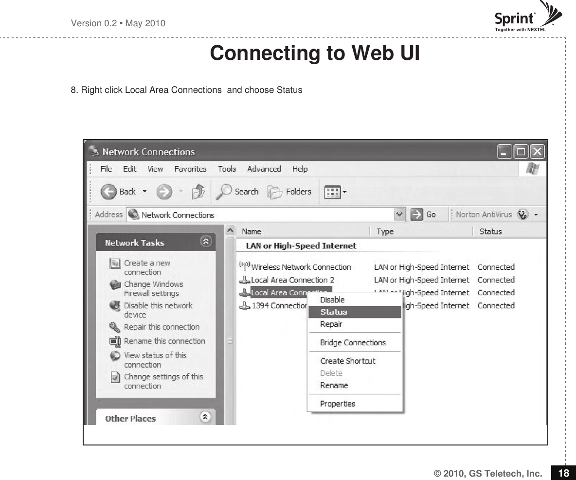
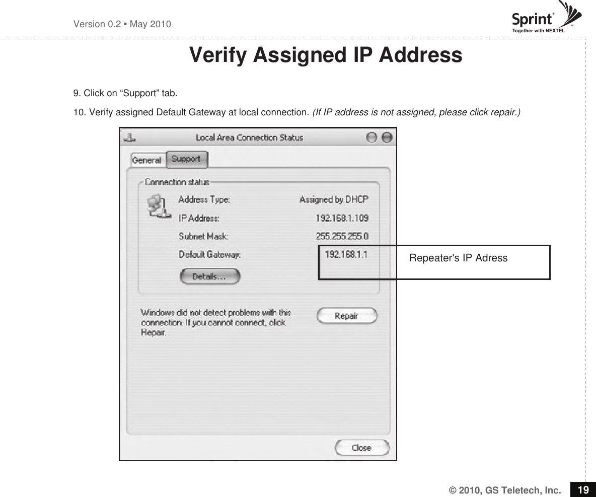
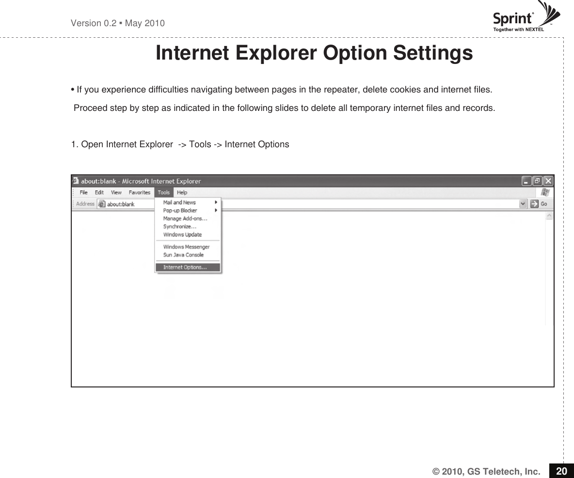
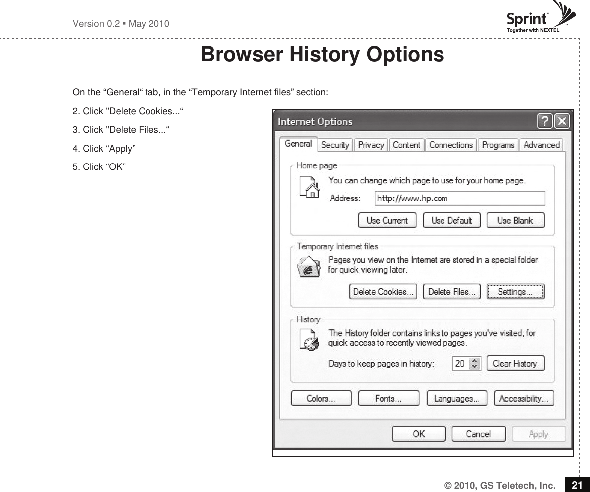
user manual 1 of 2
Contents
1.
User Manual 2 of 2
2.
user manual 1 of 2
user manual 1 of 2
Navigation menu
Upload a User Manual
Namespaces
Wiki Guide
HTML
PDF
Info
Views
User Manual
Discussion / Help
Navigation