GS Instech GRS-1930R-SPR RF Repeater User Manual ATT J Operational Description
GS Instruments Co., Ltd. RF Repeater ATT J Operational Description
Contents
- 1. User Manual 2 of 2
- 2. user manual 1 of 2
user manual 1 of 2

FCC ID : U88-GRS-1930R-SPR
HCT CO., LTD.
SAN 136-1, AMI-RI, BUBAL-EUP, ICHEON-SI, KYOUNGKI-DO, 467-701, KOREA
TEL:+82 31 639 8517 FAX:+82 31 639 8525 www.hct.co.kr
Report No. : HCTR1007FR30 1/1
ATTACHMENT E.
- USER MANUAL -
G RS -19 30 R- SP R
Repeater
I N S TA L L AT I O N G U I D E
Ve r. 0. 2
© 2010, GS Teletech, Inc. 2
Version 0.2 May 2010
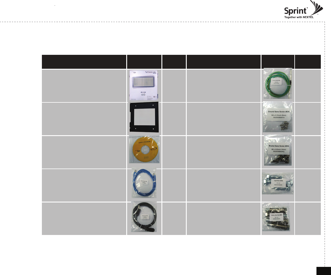
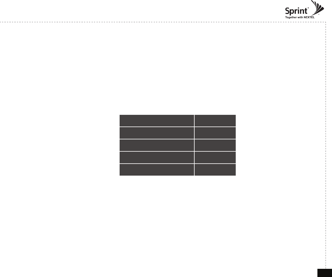
Contents of Box
Contents Picture Quantity Contents Picture Quantity
Repeater 1EA Ground Cable
6.6ft (2m) 1EA
Mounting Bracket 1EA Ground Sems Screw
M4 x 8mm 4EA
CD which Contains
User Manual Ver 1.0
and Installation Guide Ver 1.0
1EA Bracket Sems Screw
M6 x 16mm 4EA
Ethernet Cable
6.6ft (2m) 1EA Lag Screw
1/4" x 3/2" 4EA
Power Cord
10ft (3m) 1EA Anchor Bolt Set
1/4" x 3/2" 4EA
© 2010, GS Teletech, Inc. 3
Version 0.2 May 2010
The images for the User Interface in this publication may vary from the repeater’s depending on its
S/W Version.
Copyright
© 2010, GS Teletech, Inc.
All Rights Reserved
Printed in Republic of Korea
Revision History
Date Version Changes
05/2010 Draft
Certication
UL/FCC: This equipment complies with UL and FCC
© 2010, GS Teletech, Inc. 4
Version 0.2 May 2010
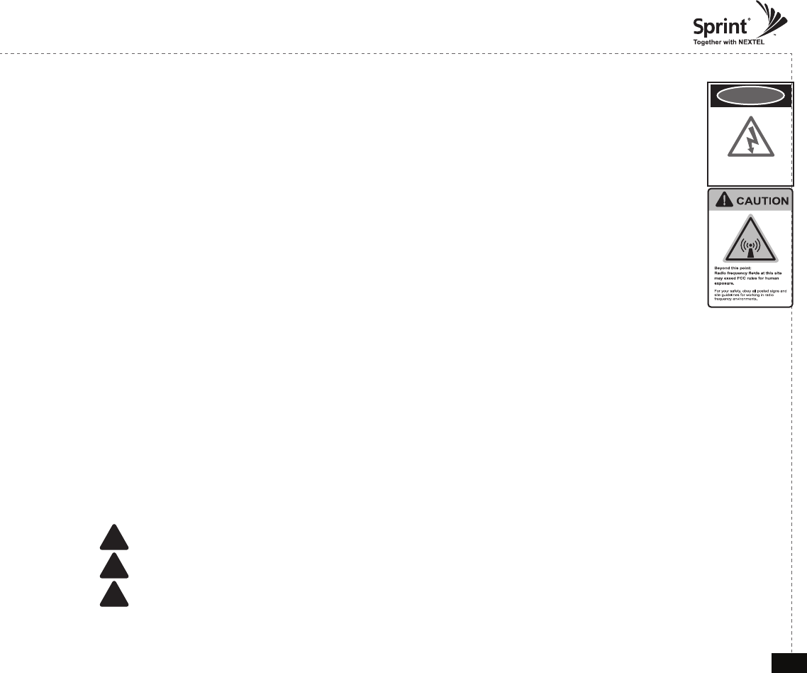
Warnings and Hazards
WARNING! ELECTRIC SHOCK
Opening the BDA (bi-directional amplier) could result in electric shock and may cause severe injury.
WARNING! EXPOSURE TO RF
Working with the repeater while in operation, may expose the technician to RF electromagnetic elds
that exceed FCC rules for human exposure. Visit the FCC website at http://www.fcc.gov/oet/rfsafety
to learn more about the effects of exposure to RF electromagnetic elds.
WARNING! DAMAGE TO EQUIPMENT
Operating the BDA with antennas in very close proximity facing each other could lead to severe damage to the repeater.
RF EXPOSURE & ANTENNA PLACEMENT
Actual separation distance is determined upon gain of antenna used.
Please maintain a minimum safe distance of at least 8inch while operating near the donor and the server antennas. Also,
the donor antenna needs to be mounted outdoors on a permanent structure.
WARRANTY
Opening or tampering the BDA will void all warranties.
!CAUTION: REPEATER SHOULD BE INSTALLED AS CLOSE AS POSSIBLE TO POWER SOURCE.
!CAUTION: THIS REPEATER IS FOR INDOOR USE ONLY AND SHOULD BE LOCATED INSIDE OF BUILDING.
!CAUTION: RISK OF EXPLOSION IF BATTERY ON CONTROLLER BOARD IS REPLACED WITH AN INCORRECT TYPE.
DANGER
electrical hazard
© 2010, GS Teletech, Inc. 5
Version 0.2 May 2010
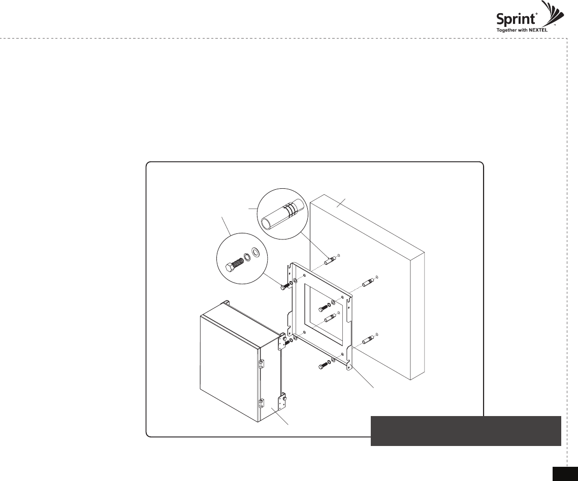
Anchor Bolt Set
1/2" x 2"
RF Repeater
Masonry Wall
Mounting Bracket
Mounting Repeater
Masonry Wall
1. Using a pencil, mark the location of each of the mounting bracket's four mounting holes on the wall.
2. Drill holes in the wall at the locations marked in step 1.
3. Set the anchors in the wall using a hammer.
4. Locate the four mounting bolts and place a lock washer and at washer on each bolt.
5. Place the mounting bracket over the four holes with anchors, making sure that the washers are on the
repeater side of the mounting bracket. Tighten bolts until secure.
<Figure 1> Mounting the Repeater
on a Masonry Wall
© 2010, GS Teletech, Inc. 6
Version 0.2 May 2010
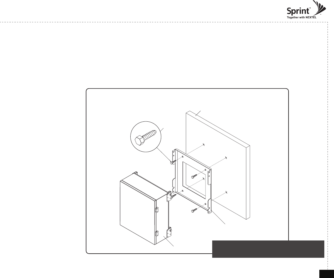
Lag Screw
1/2" x 2"
RF Repeater
Wood-Framed Wall
Mounting Bracket
Mounting Repeater
Wood-Framed Wall
1. It is recommended to rst attach a sheet of plywood to the wall. The sheet of plywood should be anchored to the studs
in the wall.
2. Using a pencil, mark the location for each of the mounting bracket's four mounting holes on the plywood.
3. Place the mounting bracket over the four lag screws heads.
4. Thread a lag screw at the positions marked in step 1.
<Figure 2> Mounting the Repeater
on a Wood-Framed Wall
© 2010, GS Teletech, Inc. 7
Version 0.2 May 2010
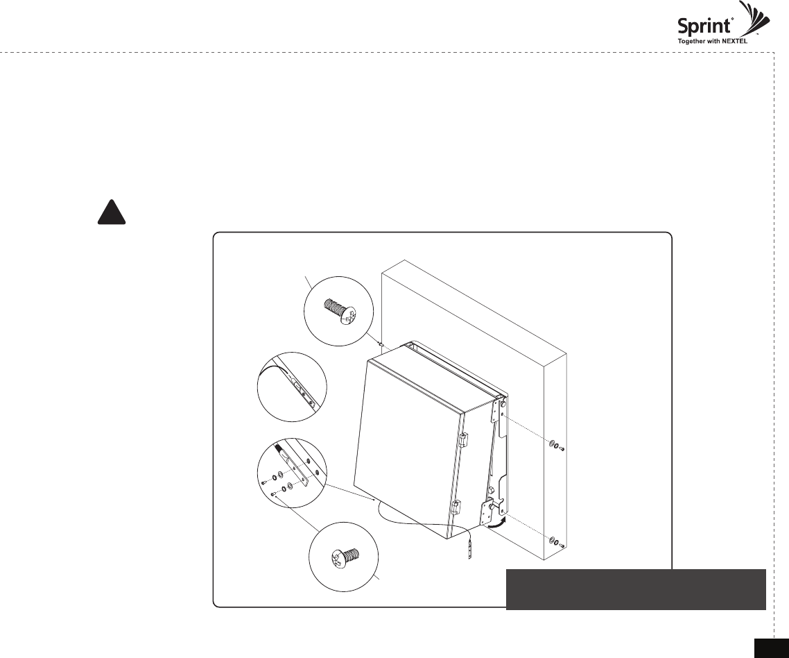
Bracket Sems Screw
M6 x 16 mm
Ground Sems Screw
M4 x 8 mm
Ground lug detail drawing
To approved ground source
Hanging and Grounding
1. Hang the Repeater from the mounting bracket.
2. Locate the four Bracket Sems Screws with installed washers. Tighten bolts until secure.
3. Locate the ground lug on the underside(or side) of the repeater.
4. Crimp the ground cable to the ground lug.
5. Route the free end of the ground cable to an approved(per local code or practice) ground source.
CAUTION
Ground cable must be properly grounded to provide both EMI and voltage surge protection for the repeater.
!
<Figure 3> Hanging and Grounding
the Repeater
© 2010, GS Teletech, Inc. 8
Version 0.2 May 2010
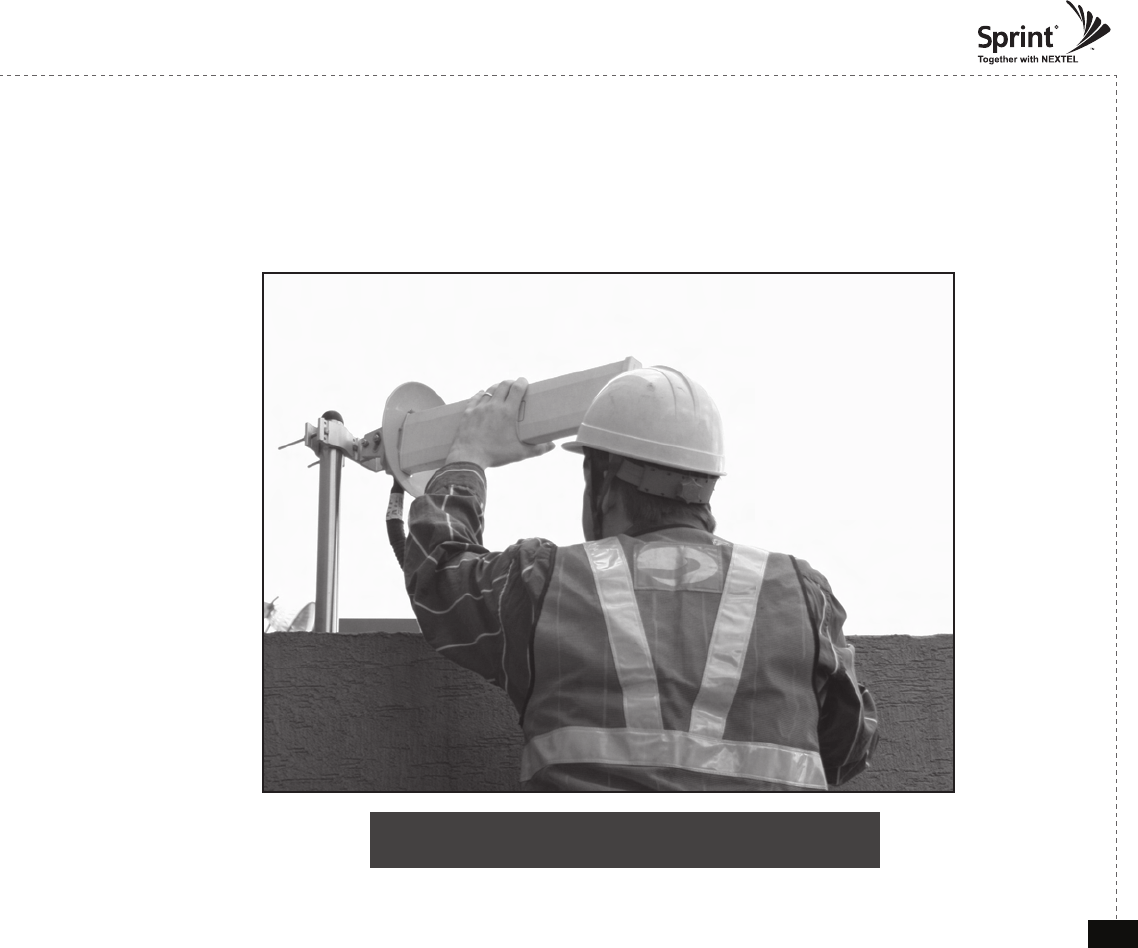
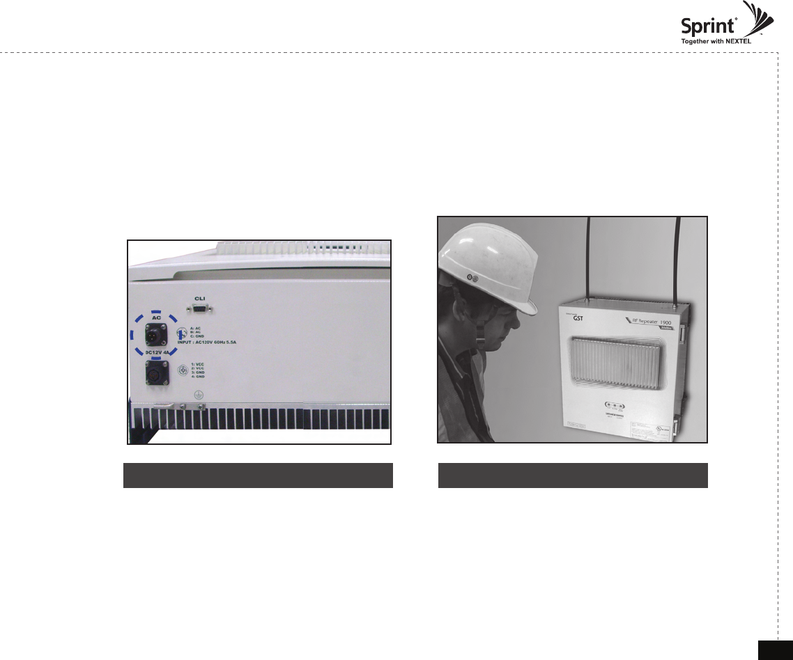
Position Antenna
• Customer specications should be followed for positioning the antennas properly.
<Figure 4> An installer is directing Donor Antenna to
nearby BTS to receive strong input signal.
© 2010, GS Teletech, Inc. 9
Version 0.2 May 2010
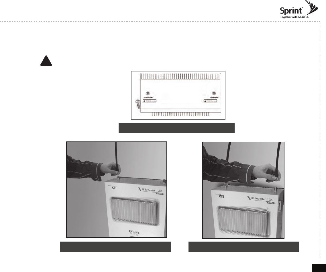
Cable Connections
• Connect Donor and Server Antennas
! CAUTION
Do not connect or disconnect cable from ANT port when power is ON
<Figure 5> ANT Ports
<Figure 7> Server ANT Port Connection <Figure 8> Donor ANT Port Connection
© 2010, GS Teletech, Inc. 10
Version 0.2 May 2010
Connecting Power Cable and LED Light Veri cation
• Connect Power Cable
<Figure 9> AC Power Port Connection <Figure 10> Verifi cation of LED Lights
© 2010, GS Teletech, Inc. 11
Version 0.2 May 2010
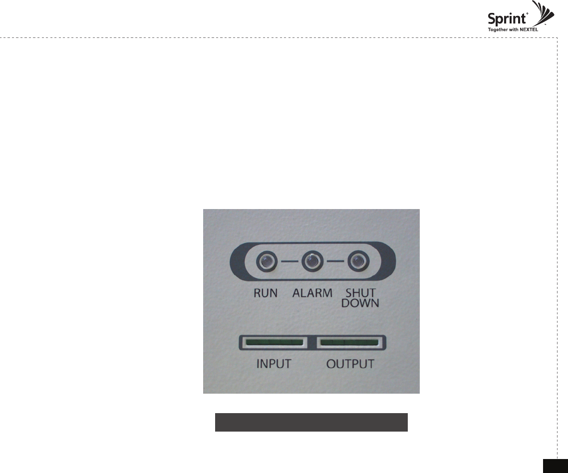
LED Indicators
• The LED’s on the repeater will light up and should change to green.
RUN LED : Green light ON
ALARM LED : Green light is normal status, Red light is alarm status
SHUT DOWN LED : Green light is normal status, Red light is shutdown status
<Figure 11> Front LED Display
© 2010, GS Teletech, Inc. 12
Version 0.2 May 2010
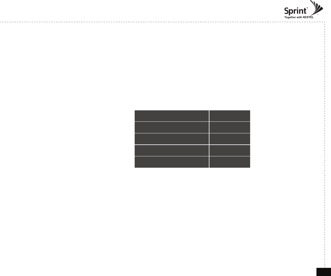
Input Power Signal
• Please note the number of LED bars for input indicates signal strength level.
• The tables below indicate the input signal levels.
CDMA 30dBm
Less than ~ -86dBm LED 1bar
-85dBm ~ -70dBm LED 2 bars
-69dBm ~ -54dBm LED 3 bars
-53dBm ~ -41dBm LED 4 bars
More than –40dBm LED 5 bars
© 2010, GS Teletech, Inc. 13
Version 0.2 May 2010
Output Power Signal
• Please note the number of LED bars for input indicates signal strength level.
• The tables below indicate the output signal levels.
CDMA 30dBm
Less than +9dBm LED 1bar
+10dBm ~ +14dBm LED 2 bars
+15dBm ~ +19dBm LED 3 bars
+20dBm ~ +24dBm LED 4 bars
More than +25dBm LED 5 bars
© 2010, GS Teletech, Inc. 14
Version 0.2 May 2010
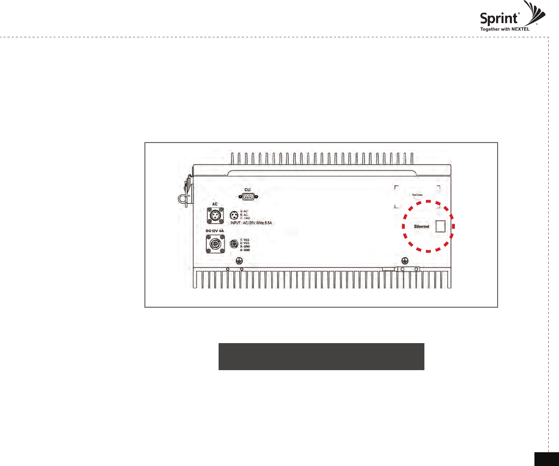
Web UI
• Before connecting to repeater, disable wireless networking functions and remove wireless broadband card.
• Connect Ethernet Crossover cable from repeater to laptop.
<Figure 12> CDMA 30 Ethernet Port Display
© 2010, GS Teletech, Inc. 15
Version 0.2 May 2010
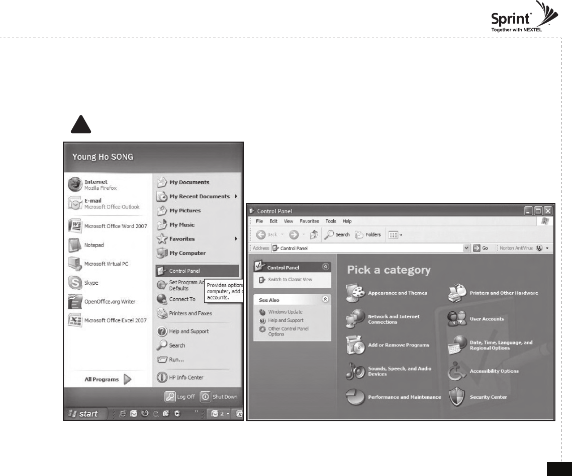
Connecting to Web UI
1. Start-> Control Panel-> Network and Internet Connections
! CAUTION
Disable wireless connections and remove wireless broadband card.
© 2010, GS Teletech, Inc. 16
Version 0.2 May 2010
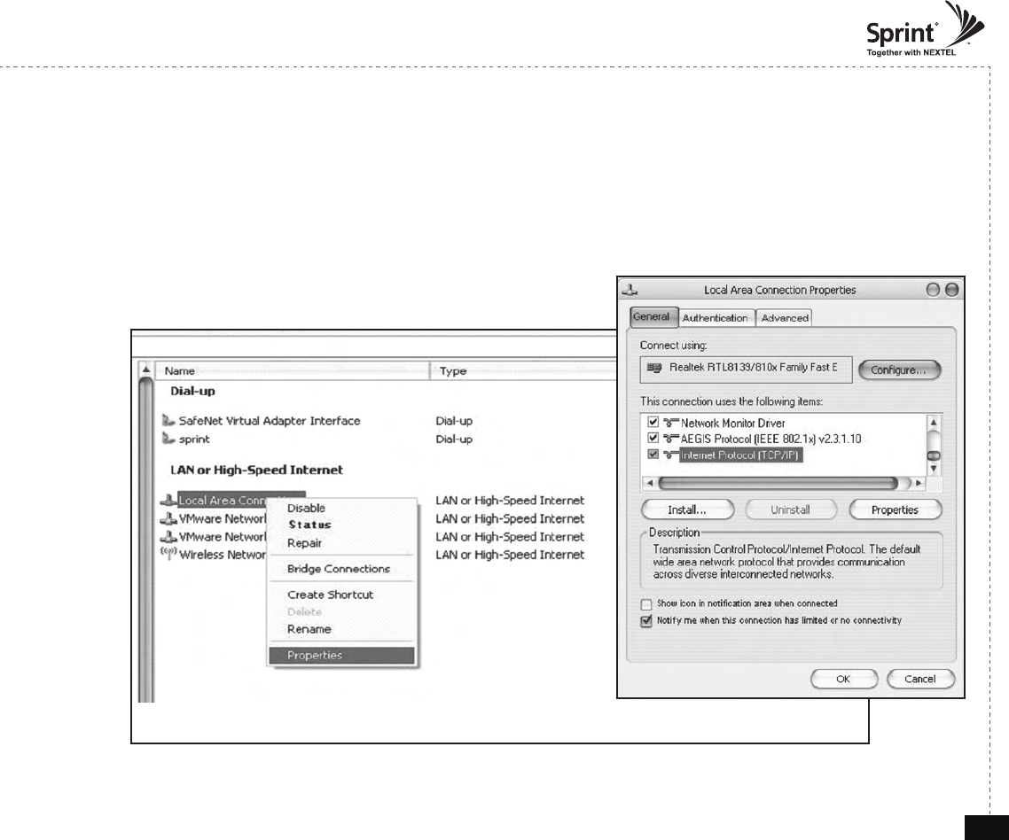
Connecting to Web UI
2. Right click Local Area Connections and choose Properties
- If your laptop is displaying multiple LAN’s, verify which one is used for repeater connection.
3. Click Internet Protocol (TCP/IP) on General Tab and click Properties
© 2010, GS Teletech, Inc. 17
Version 0.2 May 2010
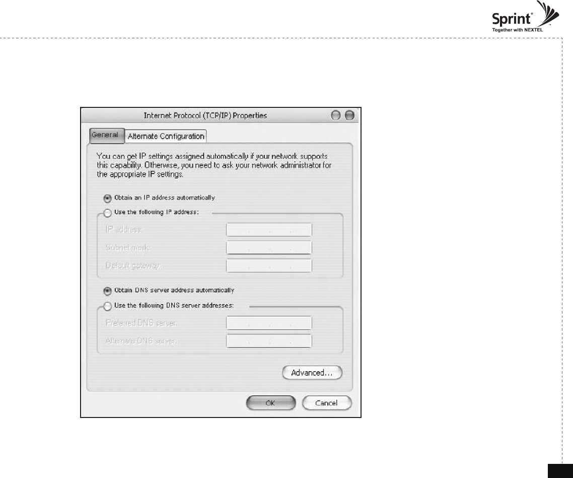
On General Tab
4. Choose “Obtain IP address automatically”
5. Choose “Obtain DNS server address
automatically”
6 . Click “OK” to close Properties
7. Click “OK” to close Properties
© 2010, GS Teletech, Inc. 18
Version 0.2 May 2010
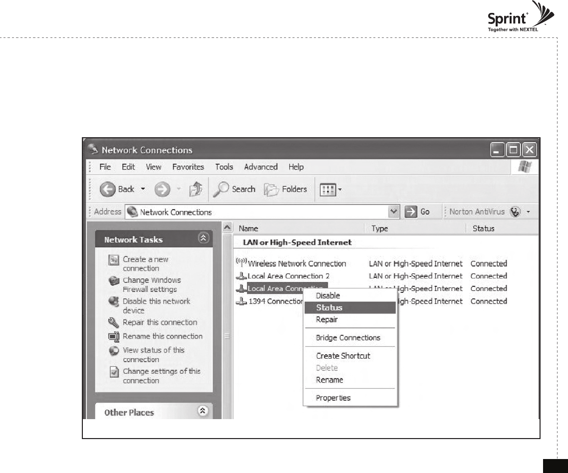
Connecting to Web UI
8. Right click Local Area Connections and choose Status
© 2010, GS Teletech, Inc. 19
Version 0.2 May 2010
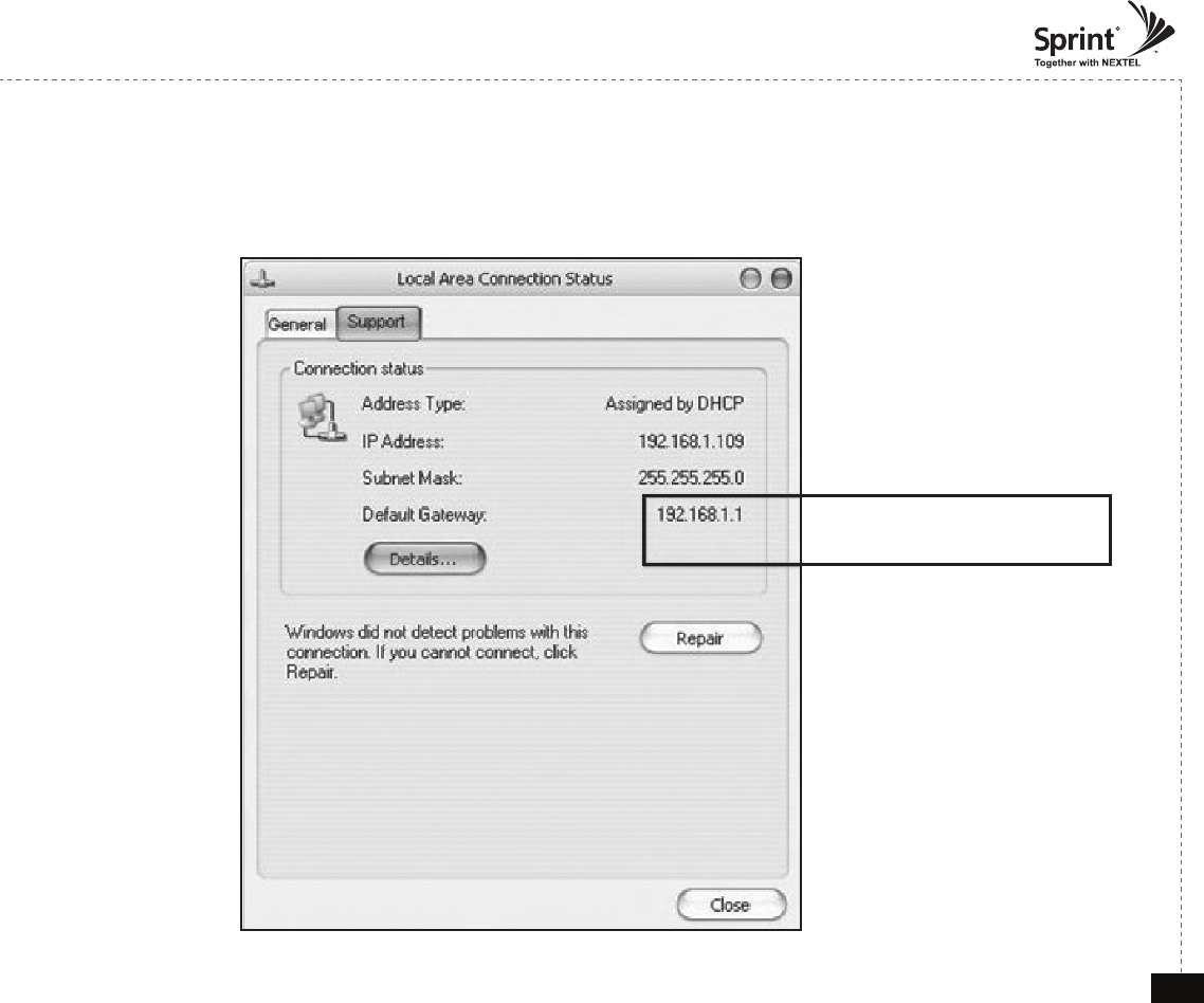
Verify Assigned IP Address
9. Click on “Support” tab.
10. Verify assigned Default Gateway at local connection. (If IP address is not assigned, please click repair.)
Repeater's IP Adress
© 2010, GS Teletech, Inc. 20
Version 0.2 May 2010
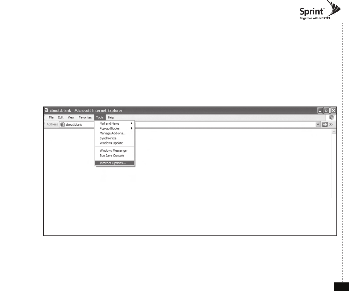
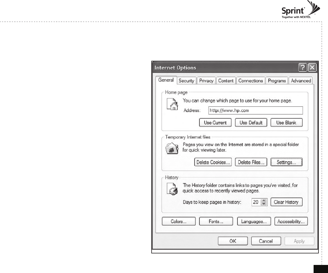
Internet Explorer Option Settings
• If you experience difculties navigating between pages in the repeater, delete cookies and internet les.
Proceed step by step as indicated in the following slides to delete all temporary internet les and records.
1. Open Internet Explorer -> Tools -> Internet Options
© 2010, GS Teletech, Inc. 21
Version 0.2 May 2010
Browser History Options
On the “General“ tab, in the “Temporary Internet les” section:
2. Click "Delete Cookies...“
3. Click "Delete Files...“
4. Click “Apply”
5. Click “OK”
© 2010, GS Teletech, Inc. 22
Version 0.2 May 2010
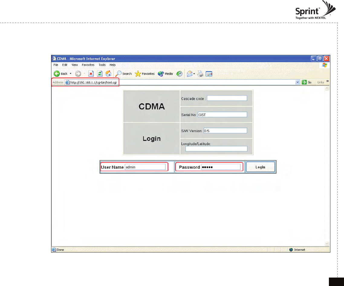
Login Screen
Enter Default Gateway’s IP address into address bar as previously described,
you will be redirected to Login. Default User Name is ‘admin’, and default
Password is ‘admin’. You may need to change password as described in the
User Management section. Cascade code and Longitude/Latitude will initially
be blank, you can input Cascade code and Longitude/Latitude as described in
‘Communications Con guration Menu’ page.
© 2010, GS Teletech, Inc. 23
Version 0.2 May 2010
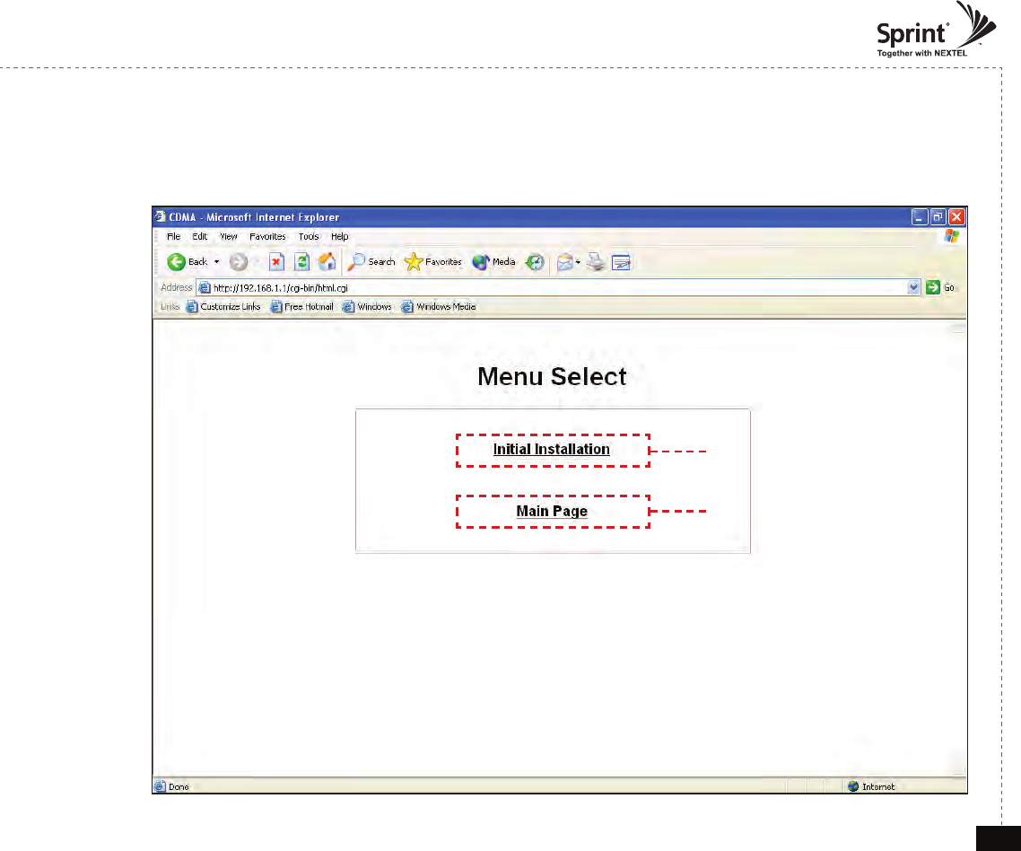
Menu Select
• After you log in, you can see menu Select page.
Setup Wizard Page Link
List Page Link
© 2010, GS Teletech, Inc. 24
Version 0.2 May 2010
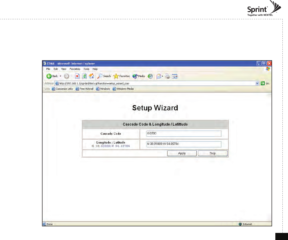
Setup Wizard
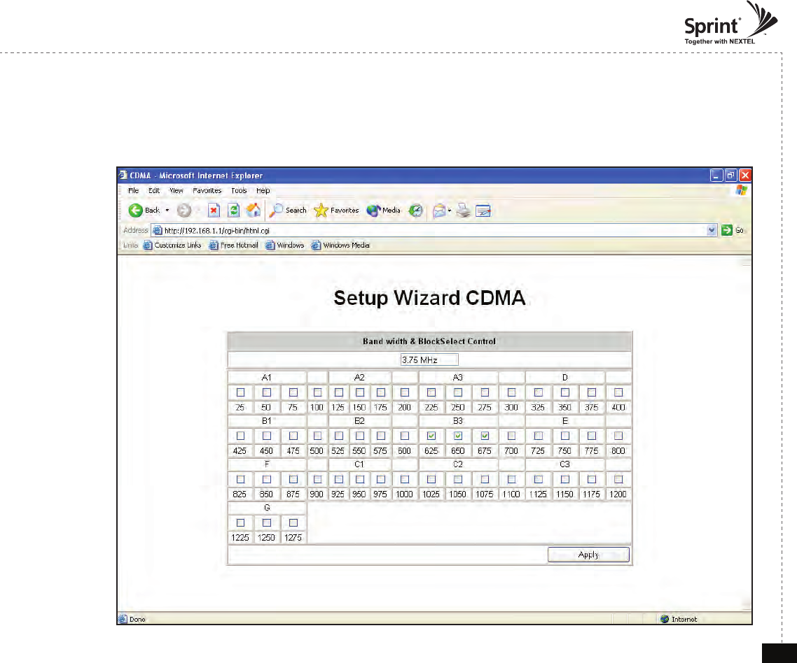
© 2010, GS Teletech, Inc. 25
Version 0.2 May 2010
Setup Wizard
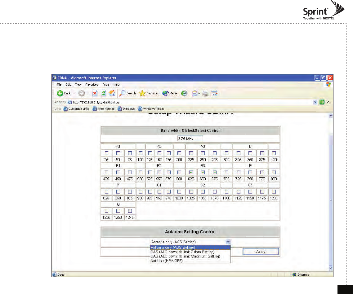
© 2010, GS Teletech, Inc. 26
Version 0.2 May 2010
Setup Wizard
© 2010, GS Teletech, Inc. 27
Version 0.2 May 2010
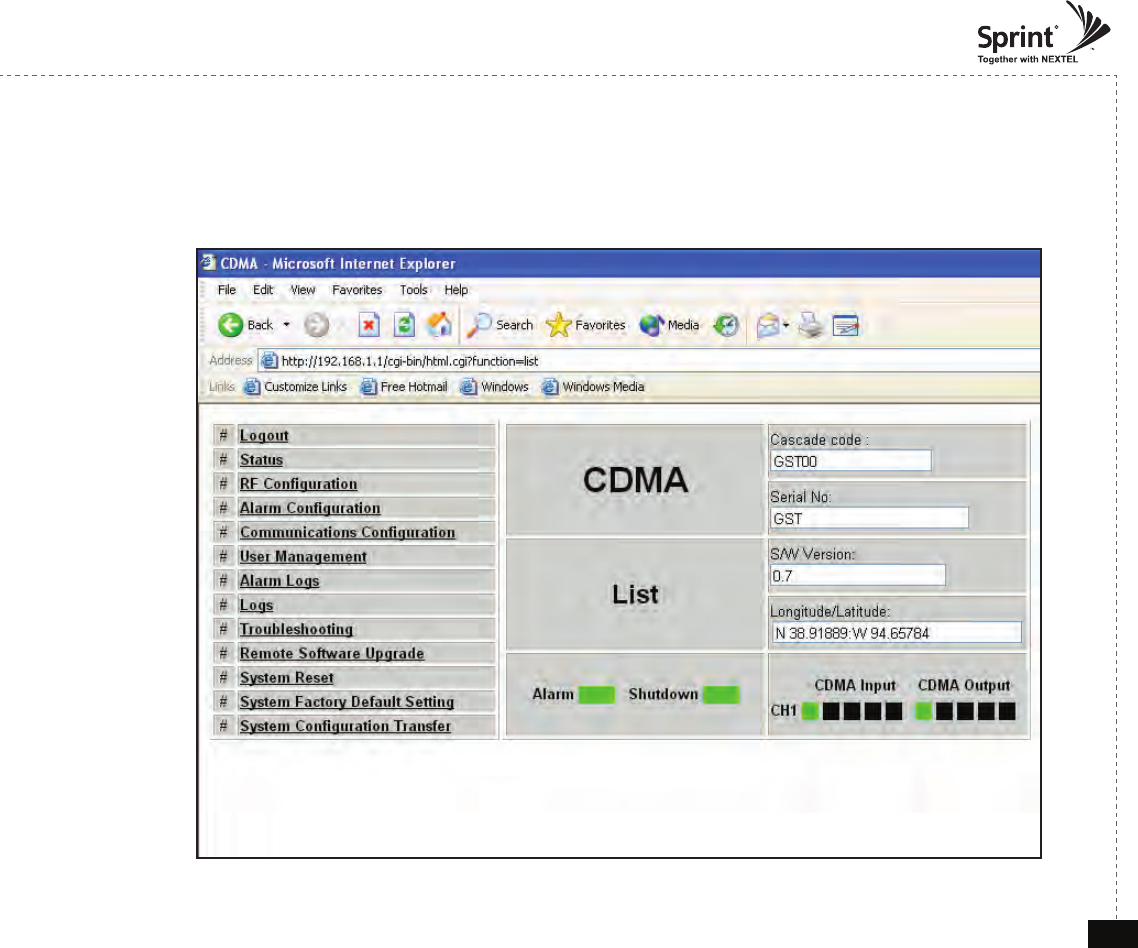
List Menu
• After you log in, you can see menu pages on the left and information about the repeater on the right.
© 2010, GS Teletech, Inc. 28
Version 0.2 May 2010
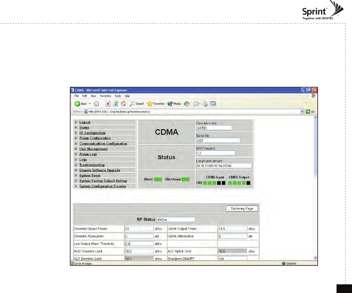
Status Menu
• Default D/L and U/L are set at minimum Gain.
• The default values in various fields will differ with different models of CDMA Repeaters.
• In order to view other pages, you can click the desired link on the top left side of the page.
© 2010, GS Teletech, Inc. 29
Version 0.2 May 2010
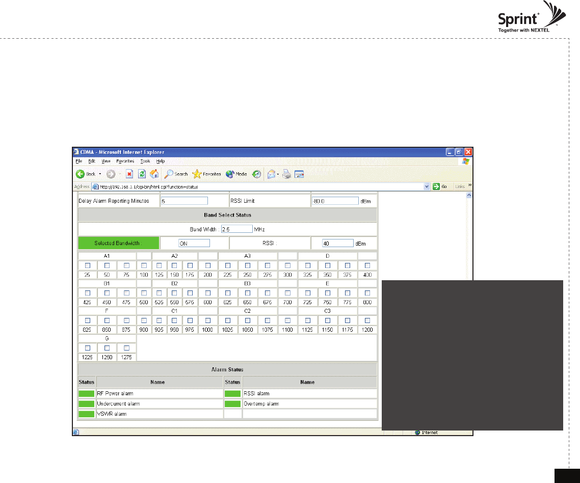
Band Select Status
• In case that screen resolution is 1024 x 768, you may need to use scroll bars to view all.
• This is where installer will verify status of the selected bandwidth and channels.
• In order to change alarm settings, click on Alarm Conguration link.
Under normal operating conditions the
Alarm Status color in the Status page is
green.
After an Alarm condition is triggered, the
Alarm Status color in Status page will be
yellow.
After an Alarm condition lasts for the
“Delay Alarm Reporting Minutes” set in
RF Conguration page, the Alarm will be
reported and the Alarm Status color in the
Status page will be red.
© 2010, GS Teletech, Inc. 30
Version 0.2 May 2010
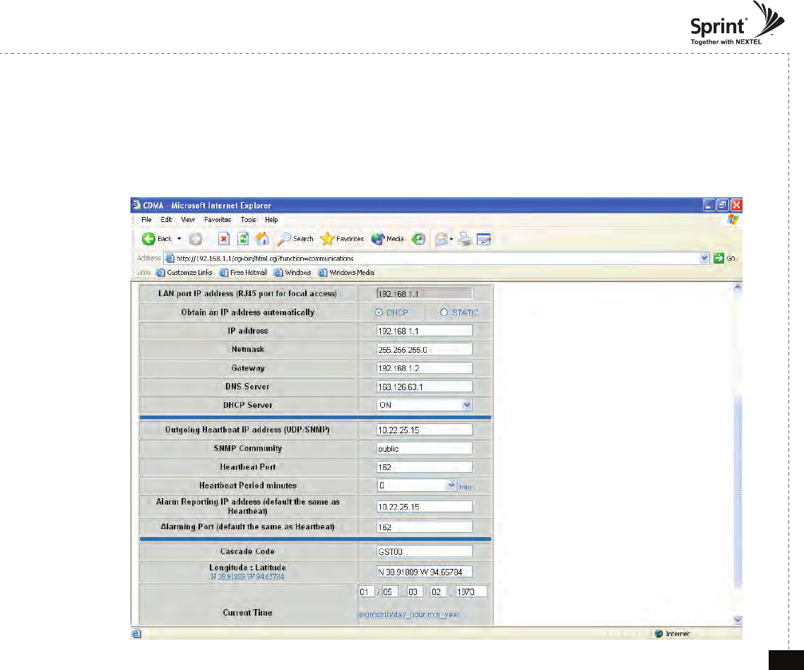
Communications Conguration Menu
• Click on the Communications Conguration link.
• On this page you can change various values related to IP network.
Because Web UI is based on IP network, incorrect conguration may make it impossible to connect to Web UI.
In that case, you can troubleshoot as described in the Command Line Interface (CLI) section.
© 2010, GS Teletech, Inc. 31
Version 0.2 May 2010
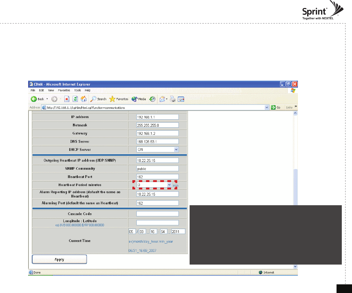
Communications Conguration Menu
• In case that screen resolution is 1024 x 768, you may need to use scroll bars to view all.
The installer can input Cascade Code, change current time & date, and input Longitude and Latitude information.
Changes will not take effect until you click “Apply” button.
When heartbeat period minutes is not “0”
-> User should input Cascade Code, Longitude, and
Latitude information of the site to turn HPA on
When heartbeat period minutes is “0”
-> User does not have to input Cascade Code, Longitude,
and Latitude information of the site to turn HPA on. (HPA is
automatically ON)
Caution : Please,
follow the example
© 2010, GS Teletech, Inc. 32
Version 0.2 May 2010
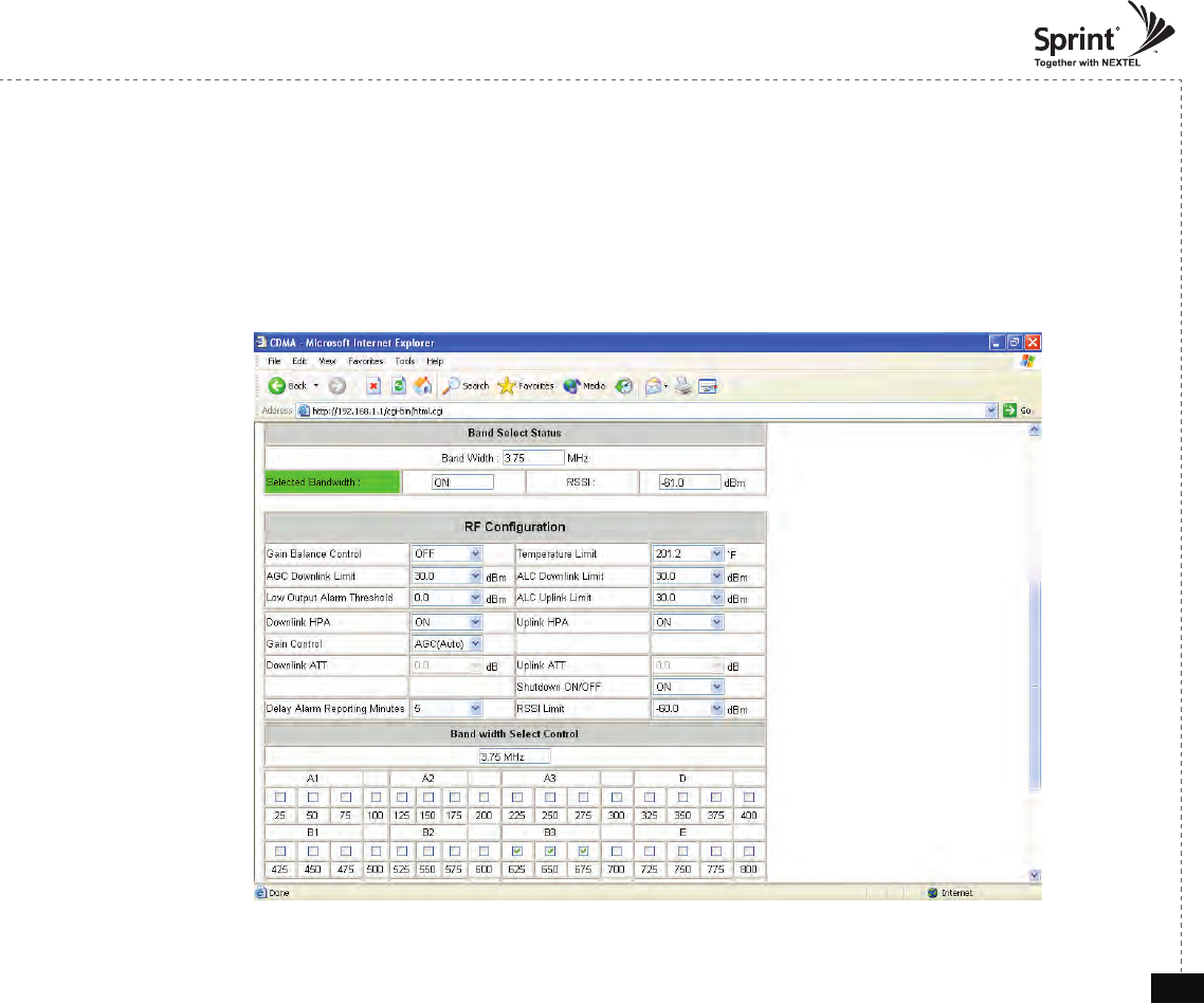
RF Conguration Menu
• Click the RF Configuration link.
• You can change various RF values of the equipment on this page.
• In case that screen resolution is 1024 x 768, you may need to use scroll bars to view all.
• Changes will not take effect until you click “Apply” button.
• This menu is where installer will choose preferences for specific implementation.
• The default values in various fields will differ with different models of CDMA Repeaters.