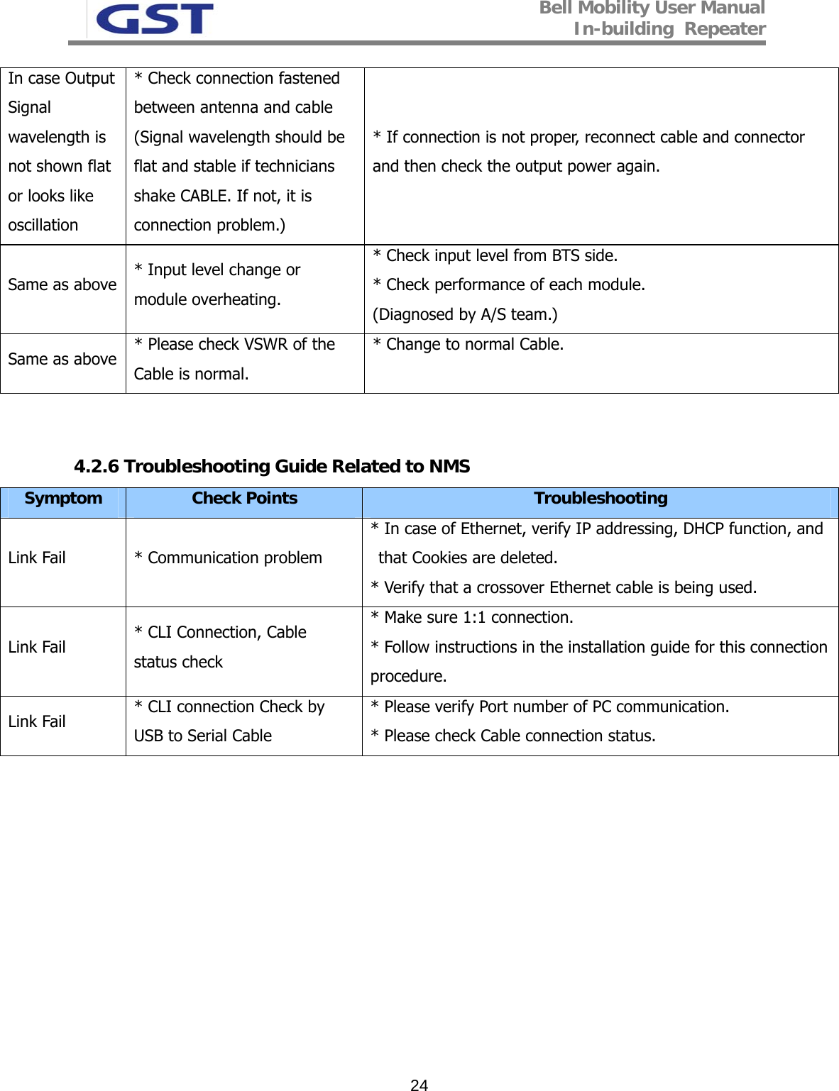
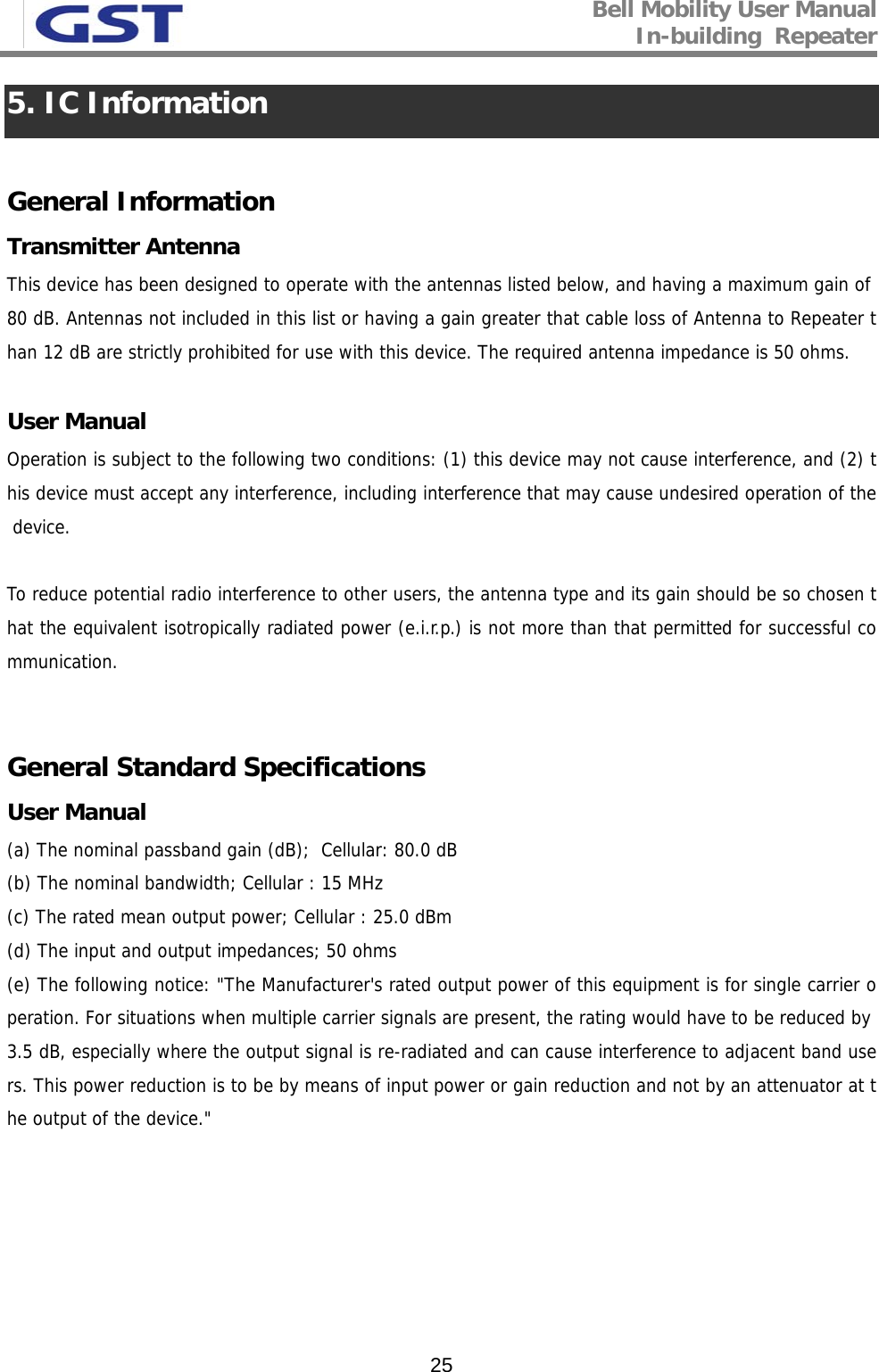
GS Instech GRS-825DM-BC Repeater User Manual

GS Instruments Co., Ltd. Repeater Users Manual

Users Manual

 FCC ID : U88-GRS-825DM-BC                                                                                                                          HCT CO., LTD. SAN 136-1, AMI-RI, BUBAL-EUP, ICHEON-SI, KYOUNGKI-DO, 467-701, KOREA TEL:+82 31 639 8517    FAX:+82 31 639 8525    www.hct.co.kr Report No. :  HCT-RF09-0416                                                    1/1    ATTACHMENT E.   - User Manual -
                                GRS-825DM-BC RF Repeater User Manual January, 2009Version 1.0
Bell Mobility User Manual In-building  Repeater   2- INDEX - 1. SUMMARY .................................................................................................................3 2. SYSTEM CONFIGURATION.....................................................................................5 2.1 In-buildingRepeater Service Network Configuration..........................................................5 2.2 System Design and Operation.............................................................................................6 2.2.1 System Design ..............................................................................................................................................6 2.2.2 Downlink/ Uplink Path .................................................................................................................................8 2.2.3 Frequency Selection.....................................................................................................................................9 3. SPECIFICATIONS...................................................................................................10 3.1 System Capacity ................................................................................................................10 3.2 System Specifications........................................................................................................11 3.3 Electrical and Environmental Specifications .....................................................................12 3.4 Functions...........................................................................................................................13 4. SETUP ......................................................................................................................15 5. IC INFORMATION..................................................................................................25
Bell Mobility User Manual In-building  Repeater   31. Summary  GRS-825DM-BC is a In-building repeater, which has been designed to improve signals in blanket/shadow areas inside of buildings to transmit Bell Mobility’s signals at nd 800MHz frequencies. Characteristics  800MHz Band: 80dB Gain with 25dBm maximum composite output power. Bandwidth: - Downlink 880MHz~894MHz, Uplink 835MHz~849MHz (14MHz Band) - See page 11 for more details.
Bell Mobility User Manual In-building  Repeater   4Characteristics  GST’s In-buildingrepeater is basically a combination of 800MHz 25dBm repeaters.  Functional modules are classified as below: - Cavity Filters to combine the Duplex input/output signals for:  800MHz.  - LNA (Low Noise Amplifier)  Gain Block to transmit output signal to PAM (Power Amplifier Module) -  Cavity Filter -  Converter Modules  - PAM Module to amplify output power linearly in accordance with optimal repeater output power.  - Power Supply Unit  - Controller to monitor each module in repeater.   Abbreviation  PAM:  POWER AMPLIFIER MODULE LNA:  LOW NOISE AMPLIFIER AGC: AUTO GAIN CONTROL ALC: AUTO LIMIT CONTROL        Caution:  Risk of explosion if battery on the controller board is replaced by an incorrect type.                                      - Statement indicating that the socket-outlet shall be installed near the equipment and shall be easily accessible.  - This equipment is indoor use and all thecommunication wirings are limited to inside of the building.
Bell Mobility User Manual In-building  Repeater   52. System Configuration 2.1 In-building Repeater Service Network Configuration  <Pic.1> In-building Repeater Service Organization
Bell Mobility User Manual In-building  Repeater   62.2 System Design and Operation 2.2.1 System Design    <Pic.2> In-building Repeater Internal Design
Bell Mobility User Manual In-building  Repeater   7    <Pic.3>> In-building Repeater Port Design
Bell Mobility User Manual In-building  Repeater   82.2.2 Downlink/ Uplink Path In-building RF Repeater simutaneously operates at 800MHz frequencies and has one Donor ANT Port for aiming at each BTS, and one Server Port for the In-building coverage. Therefore the Cavity Filters applied to the Front End of Donor ANT Port and Server ANT Port consists of DPX, has DPX which multiplexes all Tx/Rx into one path.   <Pic.4> In-buildingIn-building Repeater Block Diagram
Bell Mobility User Manual In-building  Repeater   92.2.3 800MHz Frequency Selection  Lower B (5MHz) Upper B (5MHz) B’Blank880 885 890 891.5 894MHzLower B (5MHz) Upper B (5MHz) B’Blank880 885 890 891.5 894MHz 800MHz Downlink Frequency Table  Lower B (5MHz) Upper B (5MHz) B’Blank835 840 845 846.6 849MHzLower B (5MHz) Upper B (5MHz) B’Blank835 840 845 846.6 849MHz 800MHz Uplink Frequency Table  <Pic.6 > 800MHz Band Structure  800MHz Band Select Table B (10MHz) Configuration  Lower B (5MHz)  Upper B (5MHz)  B’ (2.5MHz)1  O O 2   O 3  O  4  O   5   O  6  O  O 7   O O
Bell Mobility User Manual In-building  Repeater   103. SPECIFICATIONS  3.1 System Capacity Item  Specification  Remark DOWNLINK  880MHz ~ 894MHz  14MHz Frequency UPLINK  835MHz ~ 849MHz  14MHz Donor   Tx / Rx  DPX Port  Server Tx / Rx  DPX Capacity OMNI   Bandwidth 14MHz   Output Power (ANT Port) +25dBm / 316mW Total
Bell Mobility User Manual In-building  Repeater   113.2 System Specifications Parameter  Specification  Remark B+B’  DL: 880~894MHz UL: 835~849MHz B  DL: 880 ~ 890MHz UL: 835 ~ 845MHz B’  DL: 891.5 ~ 894MHz UL: 846.5 ~ 849MHz Band Select Lower B or Upper B DL: 880 ~ 885MHz UL: 835 ~ 840MHz Or DL: 885 ~ 890MHz UL: 840 ~ 845MHz 1dB BW Range  50dB ~ 80dB   Adjust Step  ±1.0dB   Gain Adjust Accuracy  ±0.5dB   Propagation Delay  800MHz  < 6.0us   F0±750kHz  < -45dBc  ∆marker: 29dB Spurious Emission   F0±1.98MHz  < -50dBc  ∆marker: 39dB Out Band Spurious Emission  < -13dBm  RBW: 30MHz Flatness  < ±1.25dB   Return Loss / VSWR  > 14dB /< 1.5 : 1   Uplink Noise Figure < 5dB @ Max gain < 8dB @ Min gain   ±1.5MHz  > 40dBc Roll off ±3MHz > 50dBc Test frequency measured from band edge Characteristic Impedance  50Ω
Bell Mobility User Manual In-building  Repeater   123.3 Electrical and Environmental Specifications Item  Specification  Remark RF Connector  N-Type Female  Donor & Server ANT Port AC Power Connector  DC MS3102A-10SL (3Pin) SCK-16-2P (2Pin) MIL-C-5015 Type Circular Type AC Supply  AC 120V 60Hz 3.0A   Out Dimension  450(L)*410(W)*199(H)  cm Net Weight  17.6  kgs Module AL6063S-T5   Material  Cabinet AL5052P   Operation Temperature  5  ~ +45℃℃ Convection cooling Humidity  5% ~ 95%  Non-condensing Dust Resistance  TELCORDIA GR63-CORE   Vibration Resistance  1G, 10~150Hz 0.1 Octaves/min   Environmental specifications  NEMA1    MTBF 100,000 hours
Bell Mobility User Manual In-building  Repeater   133.4 Functions Parameter  Specification Gain Control  • Adjustable DL and UL Gain range 50~80dB (800MHz)  • Display default Gain and current Gain function AGS Auto Gain Setting • AGS (Auto Gain Setting) Use for convenient Set-up  AGC Auto Gain Control • It always operates in Downlink AGC ON status • To maintain same Downlink output power despite flexible input signal strength.  • To add or subtract Attenuation level referring to AGC Power Limit level. • Used with the Automatic Setup  (Auto Gain Setting) ALC Auto Limit Control • To limit output power as far as default range  • Used for DAS configuration and when oscillation/isolation is a concern • Automatic Gain decrement when output power of repeater is higher than default level • Automatic Gain recovery when output power of repeater is reduced.  • Shutdown when output power is higher than default level in Minimum Gain • Automatic Recovery Algorithm conversion after Shutdown status Band Select  • B+B’ Band (14MHz)
Bell Mobility User Manual In-building  Repeater   14  Power Monitoring Function • Monitoring repeater’s output level Oscillation Check • Isolation Check in initial set up or Reset  • Monitoring Oscillation comparing to minimum/maximum Noise Floor level • When Oscillation occurred, repeater attempts to stabilize Isolation through Gain control function.  • Shutdown repeater when Oscillation still occurs in Minimum Gain • Automatic Recovery Algorithm conversion after Shutdown status Spurious Emission Alarm • Noise Floor Observation in case of ±2.25MHz down at the center • In case of Noise level > –13dBm, Spurious Emission is stabilized automatically • In case of Oscillation Spurious Emission Alarming in Minimum Gain, repeater will be shutdown • Automatically Switch to Recovery Algorithm at Shutdown  DL Input control   • Monitoring Donor ANT input power of DL Automatic Recovery • When repeater is shutdown, it periodically recovers output power of repeater then monitors alarming Security  • Support HTTPS for Web Browser security • User authentication through User ID and Password Temperature Control  • Monitoring temperature of repeater • Maximum and minimum set up is possible.  Shutdown in over temperature • Automatic recovery after temperature becomes normal. (Hysteresis 10degree) VSWR Monitoring • Monitoring VSWR of Donor ANT Port (Every 90 seconds) • Reporting VSWR Alarm  and Shutdown when the rate is  3:1 • Automatic Recovery Algorithm conversion after Shutdown status IP address report via E-mail • When in PPP reconnection, E-mail which includes HTML to connect to newly assigned IP Address, reports to operator.  DHCP Client   • Automatic IP assignment DHCP Server   • Server function for automatic IP assignment Web GUI   • Remote and local user browser support through Web Browser SNMP Agent   • NMS report via SNMPv2 Trap LED Display  • LED displays power and operation status on front side of repeater system.  • Input and Output signal levels are verified by LED bars.
Bell Mobility User Manual In-building  Repeater   154. SETUP 4.1. Equipment Needed for In-buildingRepeater Setup  Parameter  Item  Quantity  Remark Major Component  Repeater GRS-DUO24M-BC  1 EA  Provided by GST Additional  Components Mounting Bracket CD which contains User Manual V.1.0 and Installation Guide V.1.0 Ethernet Cable 6.6ft (2m) Ground Cable 6.6ft (2m) Ground Sems Screw M4 x 8mm Bracket Sems Screw M6 x 16mm Lag Screw 12.7mm x 50.8mm Anchor Bolt Set  12.7mm x 50.8mm1 EA 1 EA  1 EA 1 EA 4 EA 4 EA 4 EA 4 EA Provided by GST Antenna  Donor ANT Server ANT 1 EA 1 EA  Not Included RF Cable  Antenna connection Cable  TBD  Not Included Testing and Measuring Equipment  Spectrum Analyzer  1 EA  Not Included  4.1.1 Checkpoints before turning on the Repeater 1) System Power Check: AC electrical power to the repeater should be 110V, input electricity only after power verification.  2)  Input RF Signal Range: Optimal input RSSI into the repeater is -55dBm ~ -25dBm for      800MHz. User should verify input condition of Donor ANT.  If the input RSSI exceeds -20dBm, then external attenuators should be used. 3) Isolation check between DONOR/SERVER ANT: Isolation condition of this equipment is 87dBc (Gain+7dB) for 800MHz. User should check its condition before installation.
Bell Mobility User Manual In-building  Repeater   164.1.3 System Setup 1) This equipment is basically wall mountable. 2) Installer will have to connect the power supply (after verifying the input power) and RF cable to the Repeater and then it will be ready to use. 3) For grounding, there is a grounding terminal in main power supply which will be plugged into power   outlet.  There is also a separate grounding terminal on the repeater which should be connected to the  on-site grounding terminal to ensure proper grounding. 4) Mounting of repeater should be done by at least two technicians to ensure a safe and proper installation.
Bell Mobility User Manual In-building  Repeater   174.1.4   Open for Service 1) Check points before open:    a. Verification of system installation status: - Electricity, In/Out antennas, cable connection, and equipment mount status.   b. Verification of system accessories:  - User should check all necessary accessories.   c. Check receipt signal level - Installer should check whether environmental conditions are in accordance with system specification to ensure that system operation will be optimized. 2) Check points after open:  a. Check external LED 1) RUN: Green light ON   (Off: all lights off) 2) ALARM: Green light in normal status, Red light in alarming 3) SHUT DOWN: Green light in normal status, Red light in Shutdown status    800MHz 25dBm: Number of LED bars on front side of repeater will show input signal level.  Less than ~ -85dBm: LED 1bar -84dBm~-67dBm: LED 2 bars -66dBm~-49dBm: LED 3 bars -48dBm~-31dBm: LED 4 bars More than -30dBm: LED 5 bars  Number of LED bars on front side of repeater will show output power signal level.    Less than +5dBm: LED 1 Bar   +6dBm ~ +10dBm: LED 2 Bar   +11dBm ~ +15dBm: LED 3 Bar   +16dBm ~ +20dBm: LED 4 Bar   More than +21dBm: LED 5 Bar
Bell Mobility User Manual In-building  Repeater   18  <Pic.9> GRS-825DM-BC In-Building Repeater Front LED   b. Verification of operation status User should verify following status with Output monitoring terminal, which is provided by  Spectrum Analyzer: - Output power generation status, system spurious emission characteristics.   c. Verification of signal quality and strength in service area User should verify signal strength and quality of in-service coverage area by using cell phone or other measuring device.  d. Verification of upper-level NMS operation status  4.2 Troubleshooting  In case of abnormal operation, technician should diagnose abnormality via remote access or directly connecting to repeater using Ethernet cable.  If technician is required to conduct repairs due to major alarm, repeater should first be powered off, and then technician should prepare the proper measurement equipment before trying to fix the problem.  In most cases of major repairs, GST will simply replace the unit and conduct repairs at the appropriate facility.  4.2.1 Necessary Testing and Measuring Equipment
Bell Mobility User Manual In-building  Repeater   19a. RF Power Meter: 10Watt Max, 50ohm b. Signal Generator: 3GHz c. Spectrum Analyzer: 3GHz d. Multi-Meter  4.2.2 Notice a. Troubleshooting should be performed by a trained technician. b. Parts that seem to be not used should not be disassembled.  c. While troubleshooting, technician should use attenuator to check RF Signal output.  4.2.3 Simple Troubleshooting Method a.  Verify LED Status, both on external LED’s as well as internal module LED’s -  Normal operation: Green light On.  Alarming: Red LED on  b.  Technician should check external and internal connectors to ensure that all connections are  tightly secure.  These connectors should be cleaned regularly.  c. If technician thinks there is a serious problem, call after sales team for over-the-phone technical support.  1-866-9-GST-USA    (1-866-947-8872)
Bell Mobility User Manual In-building  Repeater   204.2.4 Troubleshooting Guide Item  Check Point  Trouble shooting Note before system operation * System Input power range  Input Level Downlink (800MHz)  -55dBm/Total ~ -25dBm/Total Uplink (800MHz)  -55dBm/Total ~ -25dBm/Total  Note before system operation * System Gain  Gain Downlink (800MHz)  50 ~ 80dB Uplink (800MHz)  50 ~ 80dB  Note before system operation * Output power at Server port  Output power Downlink (800MHz)  25dBm/Total Uplink (800MHz)  25dBm/Total  Check in Advance * Check points before open for    service * Please check quantity of all accessories with specification before you set up. * Fit cable length in accordance with field condition. * Set up 800MHz Donor antenna to secure Isolation (More than 87dBc) Check after open  * Check points after open for service * Check following status  - Verify that the antennas are securely mounted and pointed in the correct directions - Connection status between antennas and RF cable - Verify that the Repeater is securely mounted - Proper AC power status  - Grounding status of electrical circuit - Coaxial cable (RF) construction status  - Connectors and combiners connection status - Cable connection status against leakage of water
Bell Mobility User Manual In-building  Repeater   214.2.5 Troubleshooting Guide Related to RF Symptom  Check Point  Troubleshooting When repeater does not work properly * Check Electricity Cord connection status   * Re-plug in AC power cord When repeater does not work properly * Checking electricity input to AC power outlet.  * Please verify AC power input by using DVM (Digital Voltage Meter) When in  alarming  * DL over-input alarm * Please Check following status   - Proper maximum output power limit level - BTS input level (Spectrum Level) - Input RSSI value on Status Page  - Downlink Attenuation level * Please reset AC power upon completing Alarm                        troubleshooting When in  alarming  * DL over-output alarm * Make sure output power is operating normally.  * Reset AC power upon completing Alarm              troubleshooting. When in  alarming  * UL over-output alarm * Please make sure output level is operating normally * Please reset AC power upon completing Alarm               troubleshooting When in  alarming  * VSWR alarm * Check following status - Antenna port connection - Verify that cable from I/O filter is secure. * Disconnect all antenna cables from the repeater, terminate all antenna ports with 50Ohm terms and then reboot the repeater.  If the VSWR alarm still occurs then equipment should be replaced.  If the alarm goes away, then the VSWR issue is somewhere in the cabling or connectors.  * Reset AC power upon completing Alarm             troubleshooting When in  alarming  * IF Module alarm  * Verify IF Module LED is On.  * When LED is Off, module should be defective.
Bell Mobility User Manual In-building  Repeater   22When in  alarming  * DL, UL PAM alarm  * Reset AC power upon completing Alarm              troubleshooting When in  alarming  * DC matter/Current alarm * Verify DC power by using DVM (Digital Voltage Meter) * Reset AC power upon completing Alarm              troubleshooting. When in  alarming  * UL Oscillation * Check Isolation between Donor and Server.  * Reset AC power upon completing Alarm              troubleshooting When in  alarming  * DL / UL LNA alarm * Check connection status of LNA. * Reset AC power upon completing Alarm              troubleshooting   When in  alarming  * Temperature alarm * Check following status: - Setting level of maximum temperature limit  - Temperature offset is normal or not.  - Circumstances of temperature.  * Reset AC power upon completing Alarm              troubleshooting When in  alarming  * DL low-input alarm  * Reset AC power upon completing Alarm              troubleshooting  When in  alarming  * DL low-output alarm * Check following status - Output power level is normal or not.   - Whether minimum output limit level is normal.  - Compare RSSI to maximum gain. * Reset AC power upon completing Alarm              troubleshooting When in  alarming * RF OFF * Verify that the HPA’s are On. * Reset AC power upon completing Alarm              troubleshooting When output power is  no longer problem  * Technician should verify category of alarm at the front side of repeater.  * When Red light on the Shutdown LED, technician should troubleshoot the alarm via Notebook computer.
Bell Mobility User Manual In-building  Repeater   23When output power is  no longer problem  * Technician should connect antenna with output port of repeater.  * Please make sure all connectors are fastened  * Reconnect the connector. * Change it if the connector is defective.  When output power is  no longer problem  * Check the input level   * Increase output power or check input change of BTS side.  When output power is  no longer problem  * Check Gain of the unit  * If the Gain is different from normal level, please contact A/S team. When output power is  no longer problem  * Cable connector loose.   * It is possible for connectors to get too tight and damage the equipment or throughput. * Please contact installer or service provider upon verification.  In case of dropped call or bad  signal after  set up  * Check input signal strength in the service area   * Increase output power level of repeater by adjusting         attenuation level. In case of drop call or bad  signal after  set up  * If input signal strength is not a problem, please check delay of calling time.   * Increase output level of Uplink signal, then set to optimal level. In case of dropped call or bad  signal after  setup  * Check RSSI signal strength  * Contact network management team or service provider
Bell Mobility User Manual In-building  Repeater   24In case Output Signal wavelength is  not shown flat  or looks like  oscillation * Check connection fastened between antenna and cable  (Signal wavelength should be flat and stable if technicians shake CABLE. If not, it is connection problem.)   * If connection is not proper, reconnect cable and connector and then check the output power again. Same as above  * Input level change or    module overheating.  * Check input level from BTS side. * Check performance of each module. (Diagnosed by A/S team.) Same as above  * Please check VSWR of the Cable is normal.  * Change to normal Cable.    4.2.6 Troubleshooting Guide Related to NMS Symptom  Check Points  Troubleshooting Link Fail   * Communication problem * In case of Ethernet, verify IP addressing, DHCP function, and that Cookies are deleted. * Verify that a crossover Ethernet cable is being used. Link Fail   * CLI Connection, Cable       status check  * Make sure 1:1 connection. * Follow instructions in the installation guide for this connection procedure. Link Fail   * CLI connection Check by USB to Serial Cable  * Please verify Port number of PC communication. * Please check Cable connection status.
Bell Mobility User Manual In-building  Repeater   255. IC Information  General Information Transmitter Antenna This device has been designed to operate with the antennas listed below, and having a maximum gain of 80 dB. Antennas not included in this list or having a gain greater that cable loss of Antenna to Repeater than 12 dB are strictly prohibited for use with this device. The required antenna impedance is 50 ohms.  User Manual Operation is subject to the following two conditions: (1) this device may not cause interference, and (2) this device must accept any interference, including interference that may cause undesired operation of the device.  To reduce potential radio interference to other users, the antenna type and its gain should be so chosen that the equivalent isotropically radiated power (e.i.r.p.) is not more than that permitted for successful communication.   General Standard Specifications User Manual (a) The nominal passband gain (dB);  Cellular: 80.0 dB (b) The nominal bandwidth; Cellular : 15 MHz (c) The rated mean output power; Cellular : 25.0 dBm (d) The input and output impedances; 50 ohms (e) The following notice: "The Manufacturer's rated output power of this equipment is for single carrier operation. For situations when multiple carrier signals are present, the rating would have to be reduced by 3.5 dB, especially where the output signal is re-radiated and can cause interference to adjacent band users. This power reduction is to be by means of input power or gain reduction and not by an attenuator at the output of the device."

Navigation menu