GS Instech GSTICELITE1943 LTE/CDMA ICS RF Repeater User Manual GST IC ELITE 1943 V1 3 Rev 1
GS Instech Co., Ltd. LTE/CDMA ICS RF Repeater GST IC ELITE 1943 V1 3 Rev 1
UserManual.wiki
>
GS Instech
>
GSTICELITE1943 User Manual
GST-IC-ELITE-1943_User Manual_V1.3_Rev.1
Navigation menu
Upload a User Manual
Namespaces
Wiki Guide
HTML
PDF
Info
Views
User Manual
Discussion / Help
Navigation
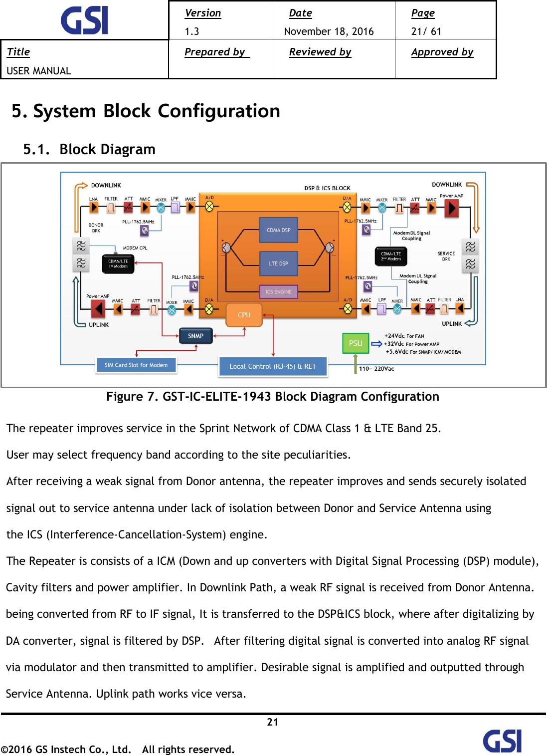
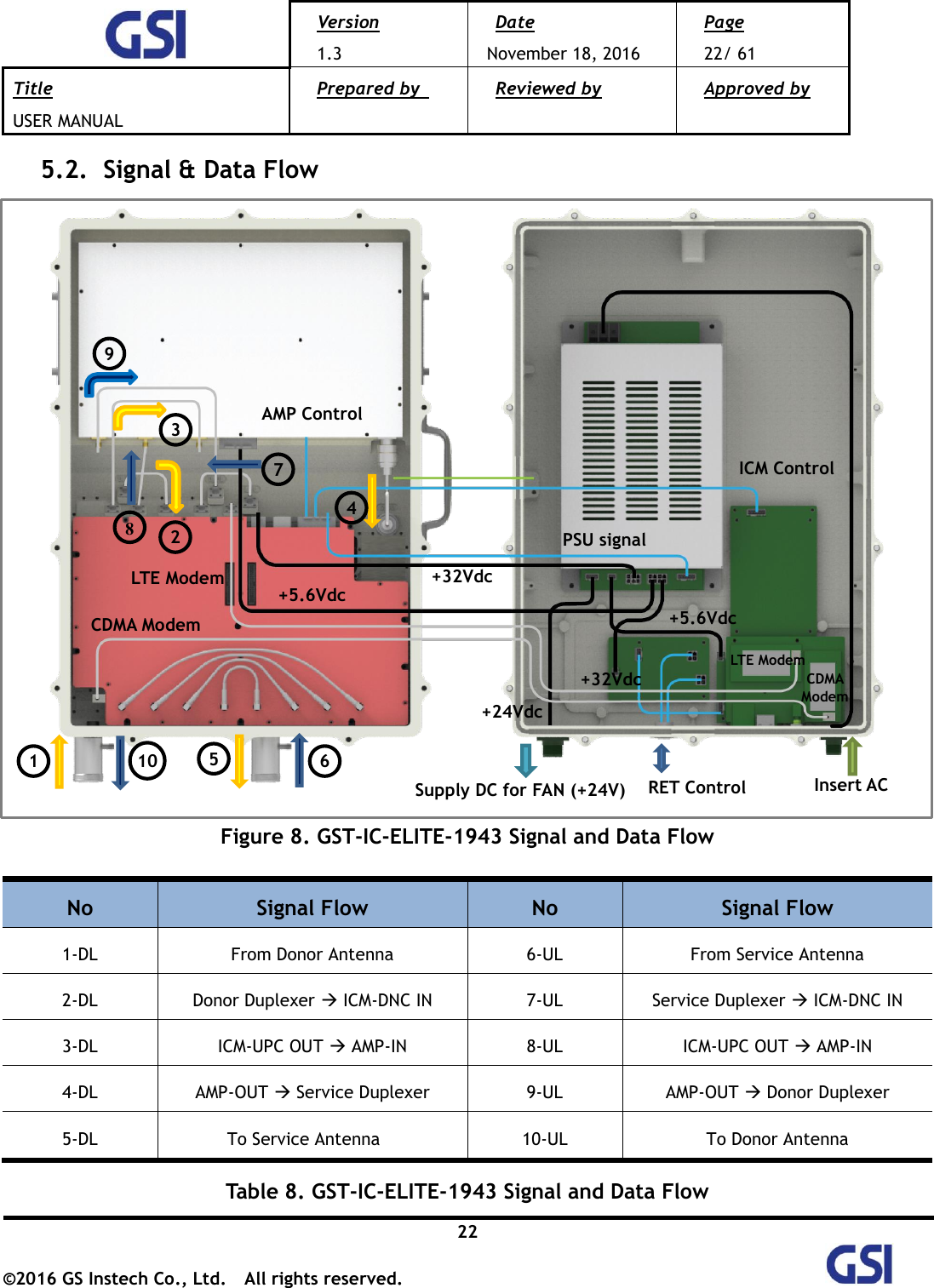
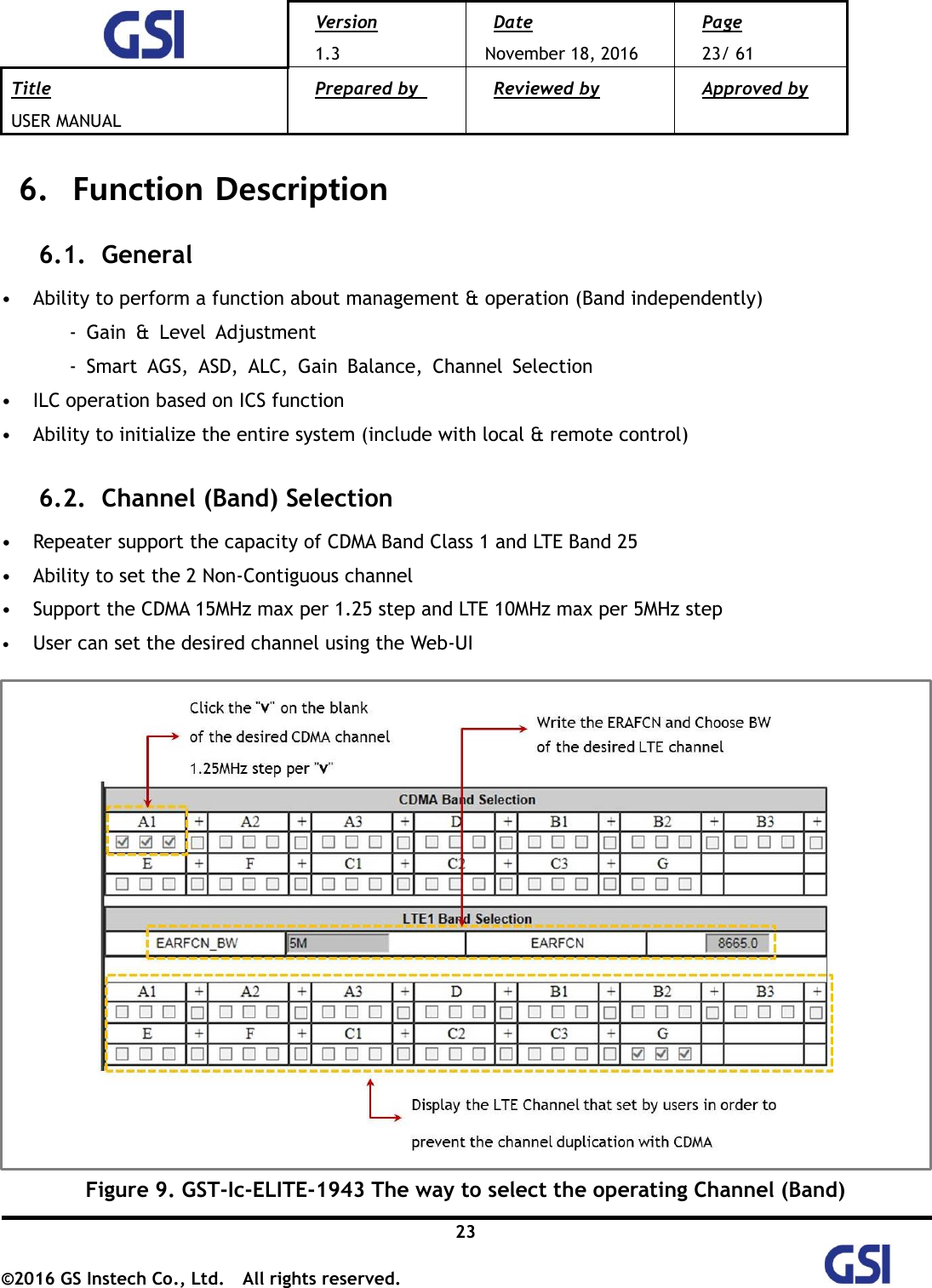
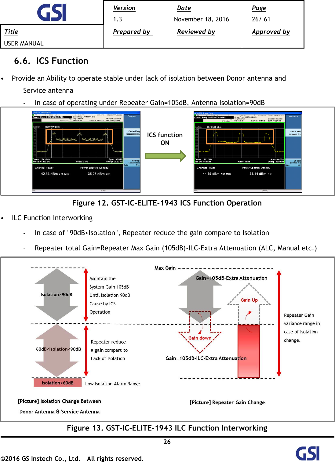
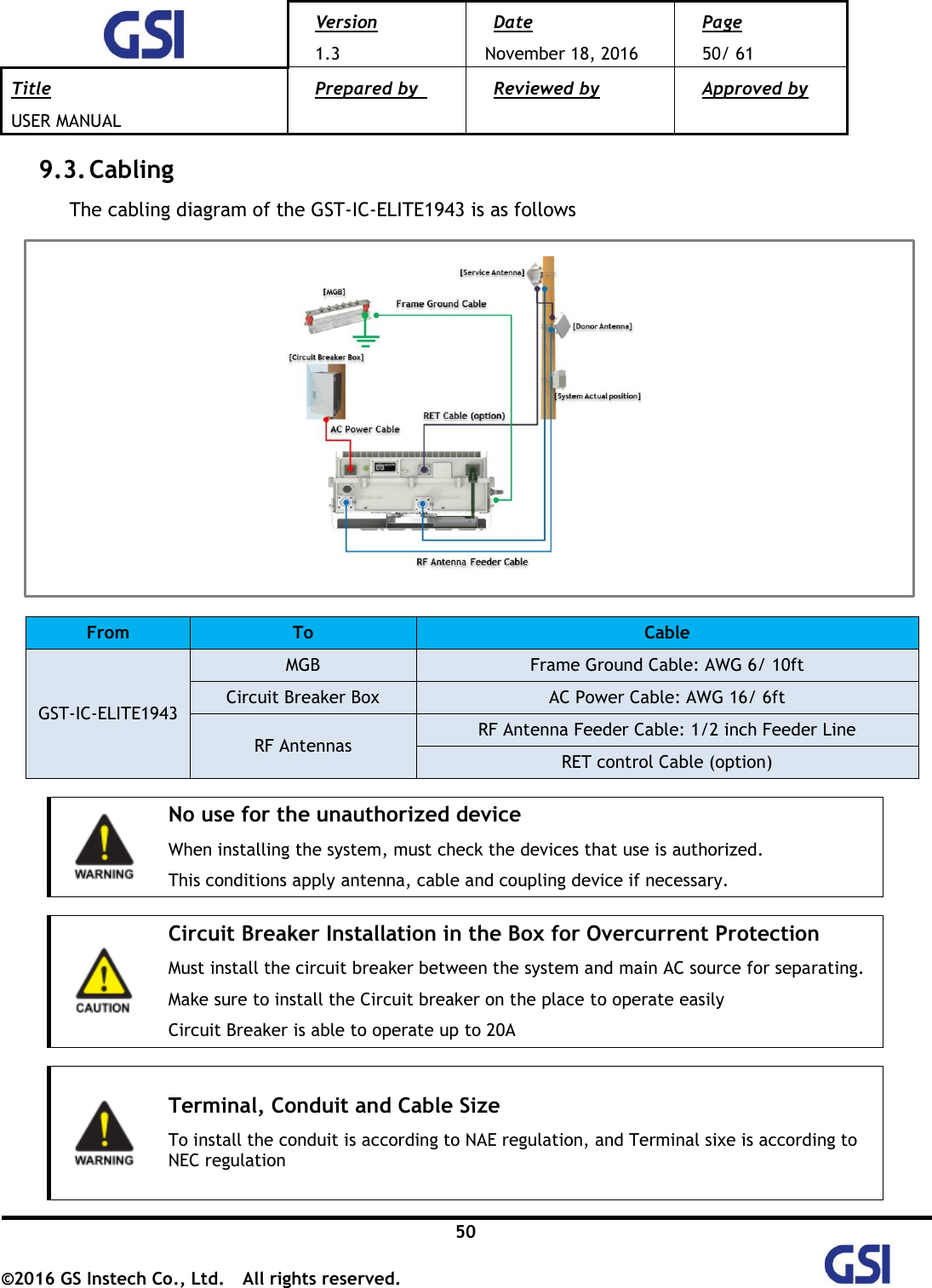
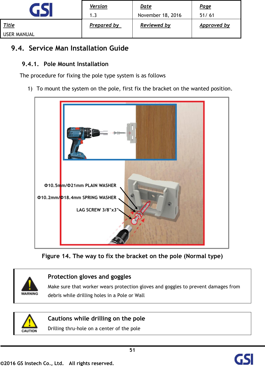
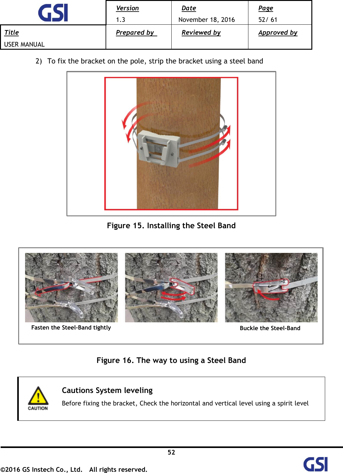
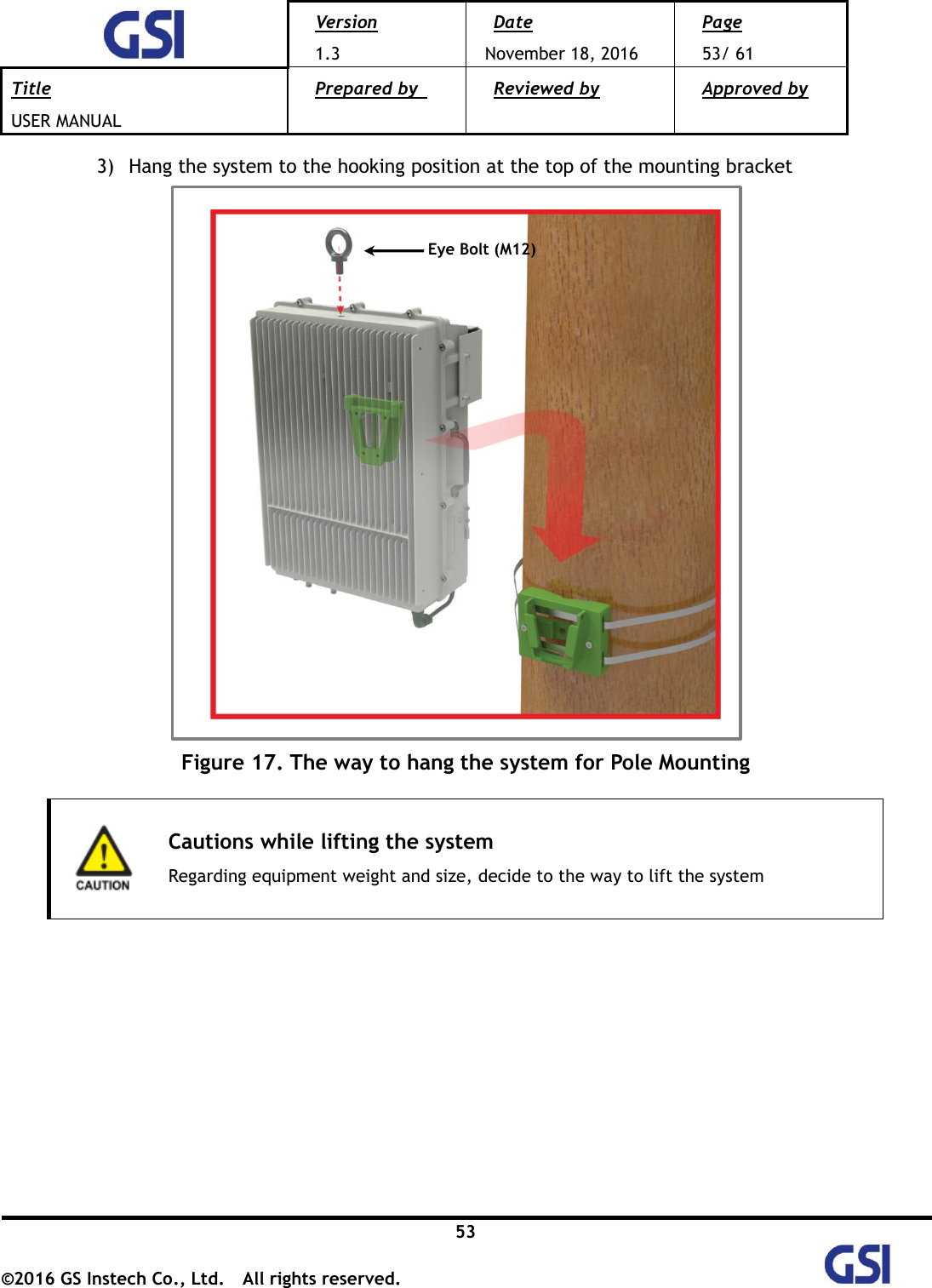
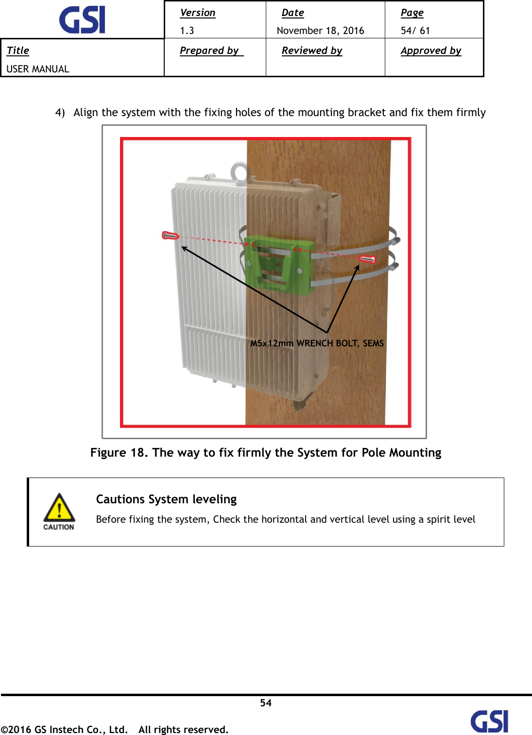
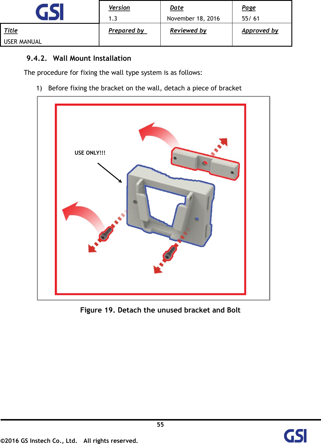
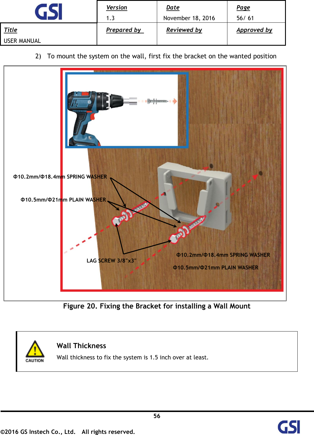
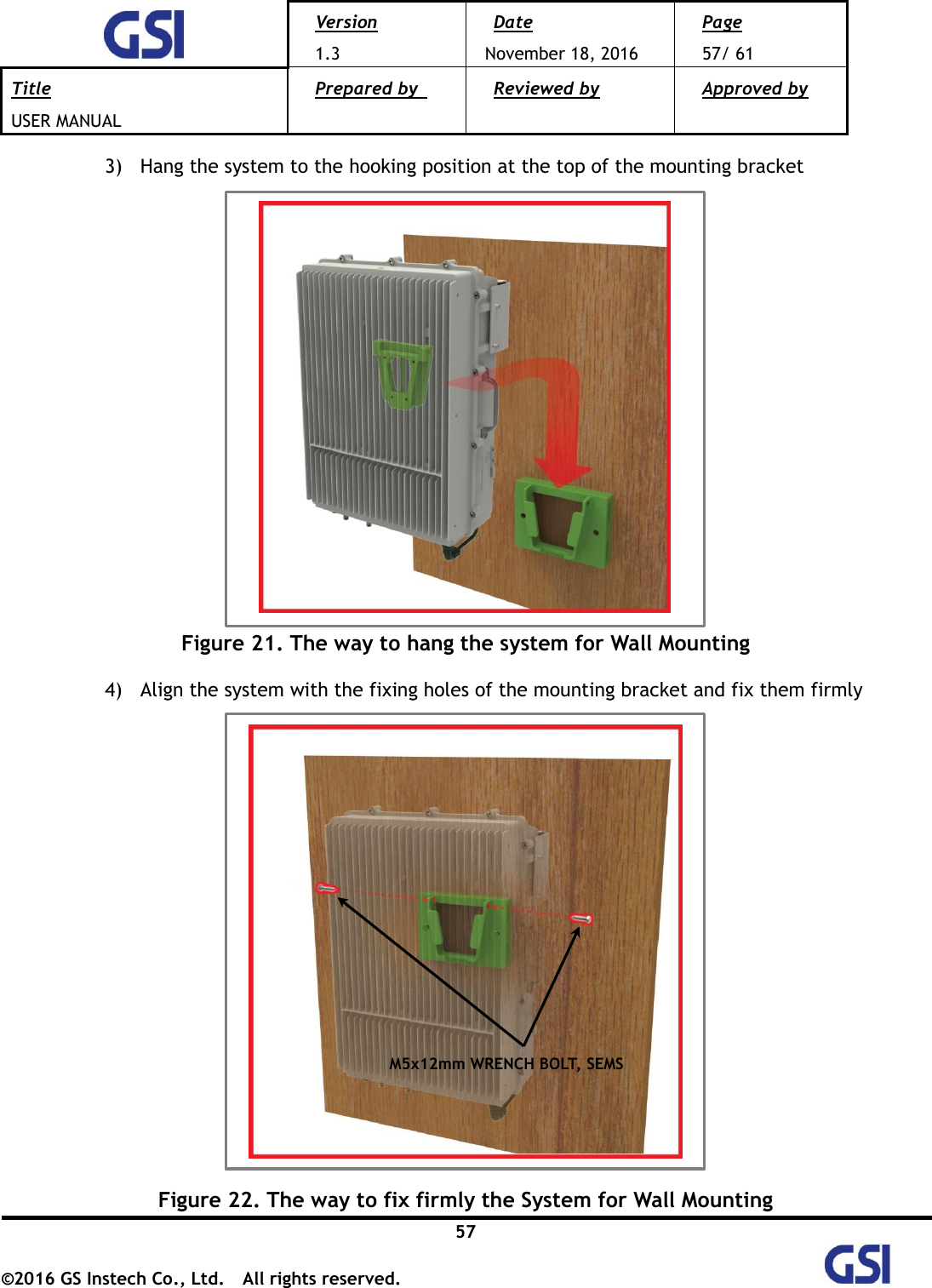
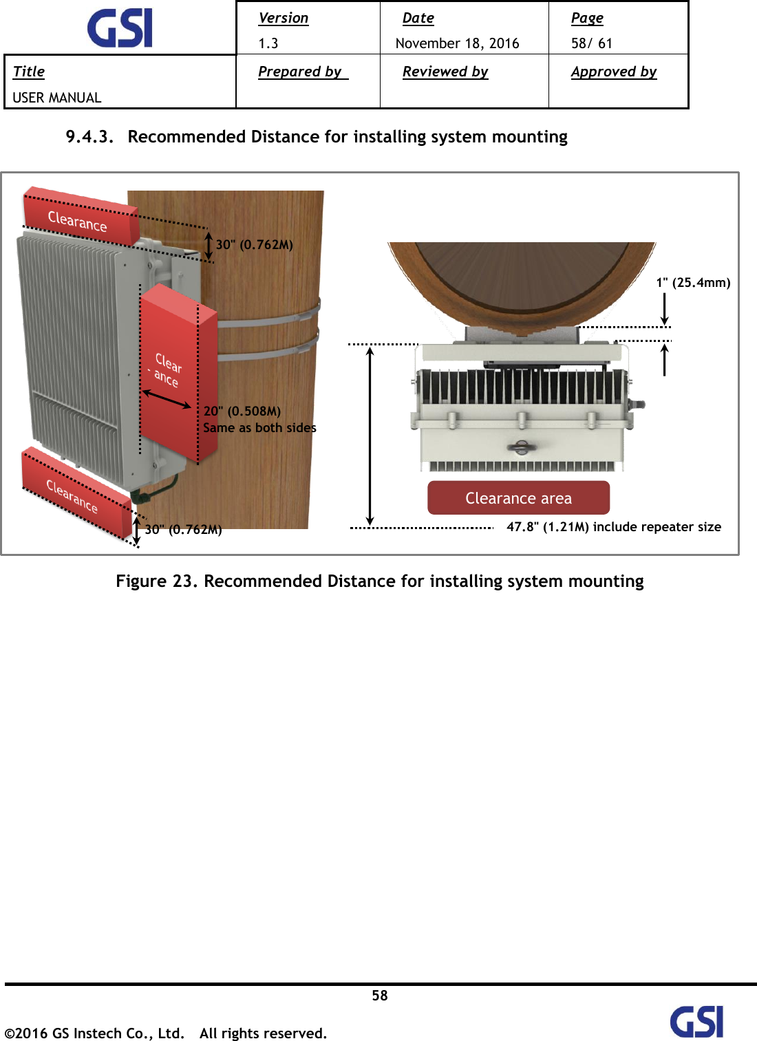
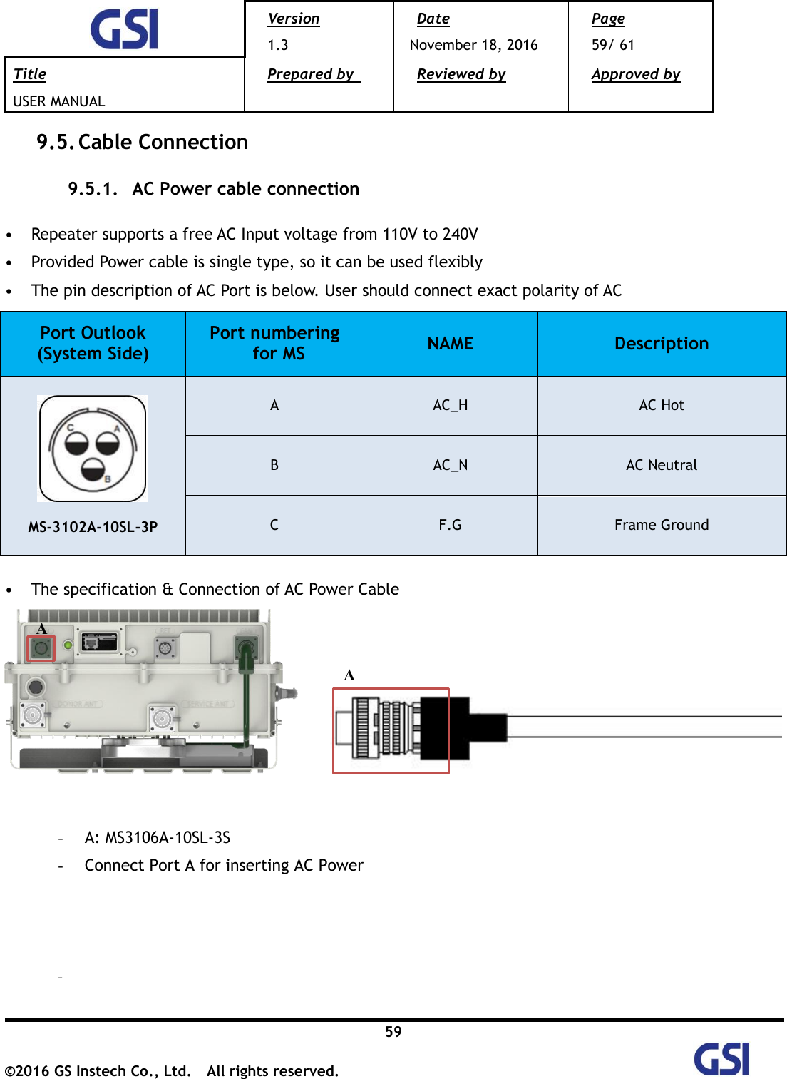
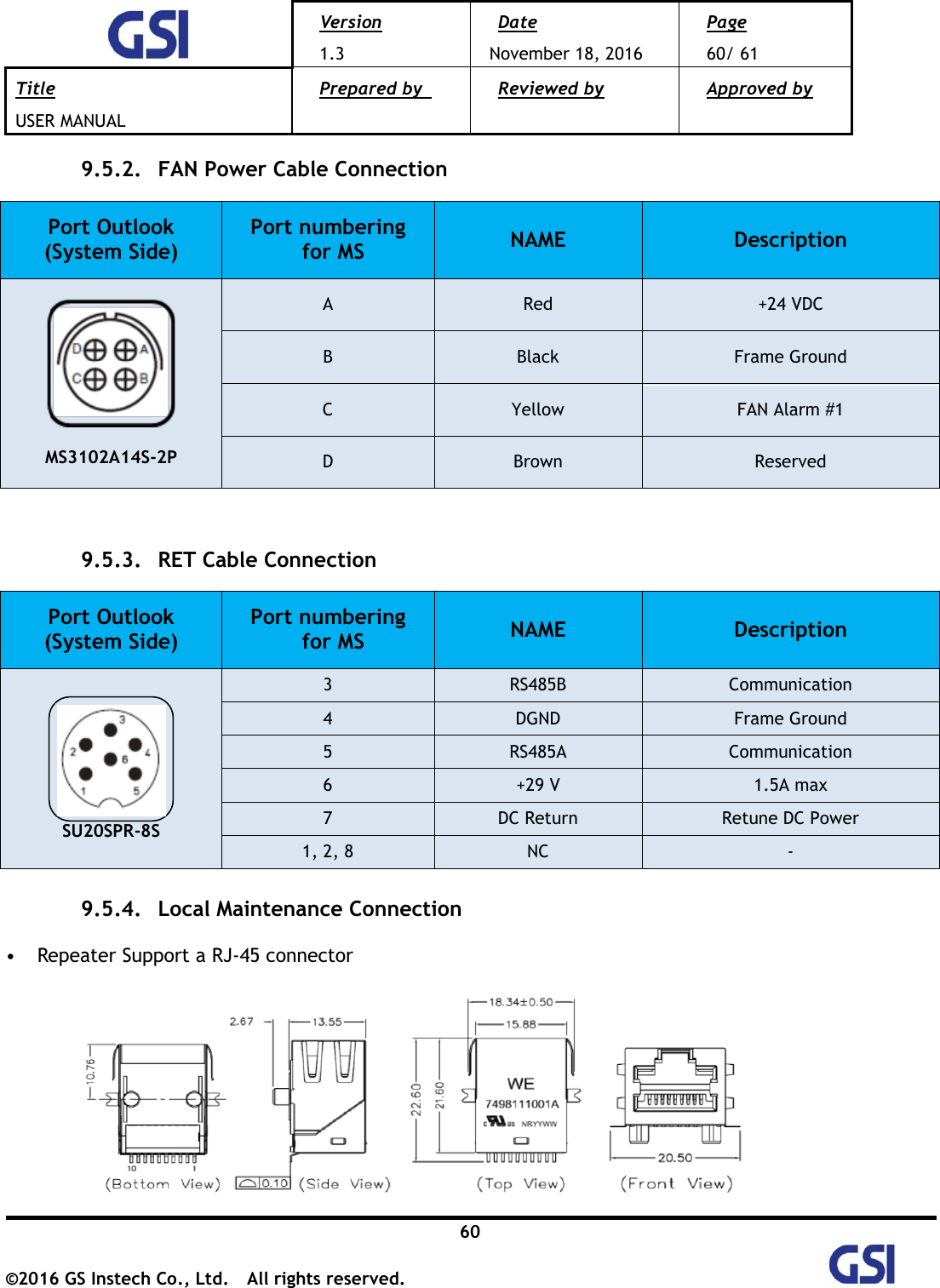
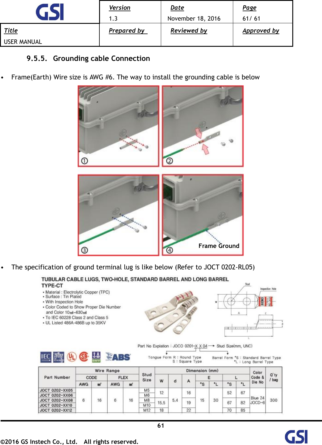
![Version 1.3 Date November 18, 2016 Page 2/ 61 Title USER MANUAL Prepared by Reviewed by Approved by 2 ©2016 GS Instech Co., Ltd. All rights reserved. [CHANGE RECORD] DATE NAMES DESCRIPTIONS VERSION REMARK September 5, 2016 H.J.CHOI Original Draft 1.0 September 23th, 2016 H.J.CHOI Add a Modem redundant Configuration 1.1 November 11, 2016 H.J.CHOI Change a Model Number 1.2 Edit contents November 18, 2016 H.J.CHOI Edit according to FCC/ UL Regulation 1.3](https://usermanual.wiki/GS-Instech/GSTICELITE1943/User-Guide-3205849-Page-2.png)
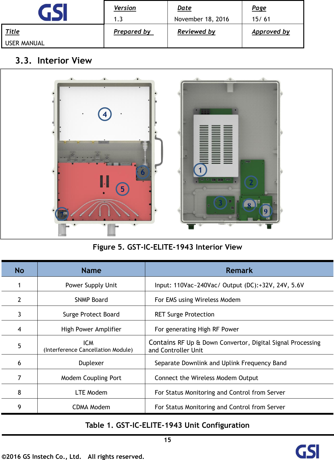
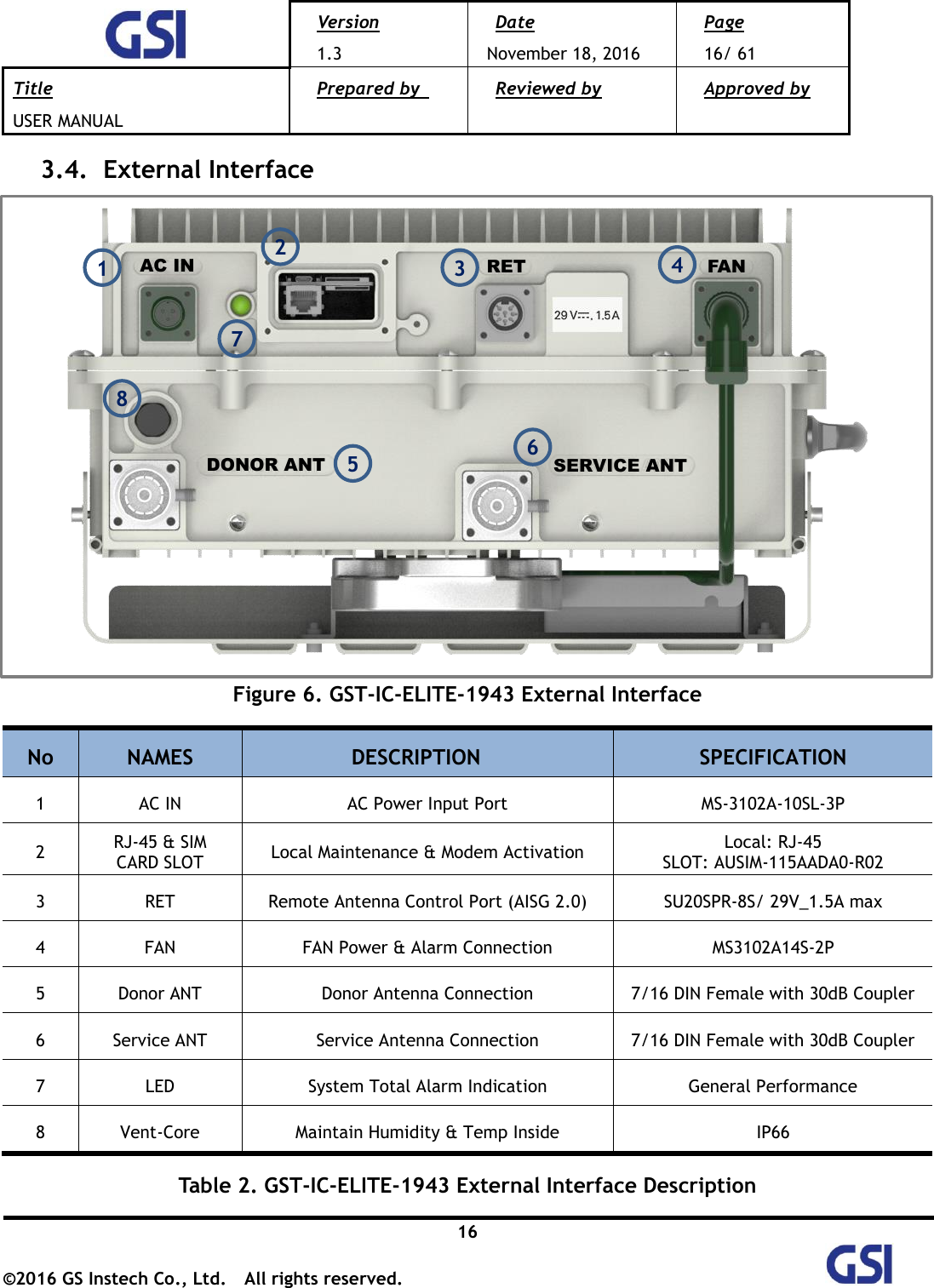
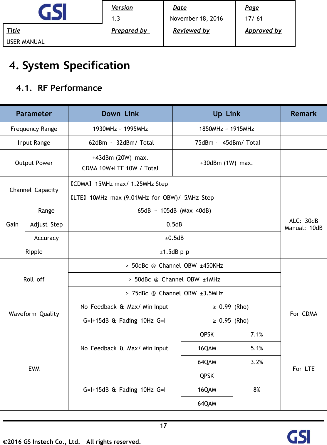
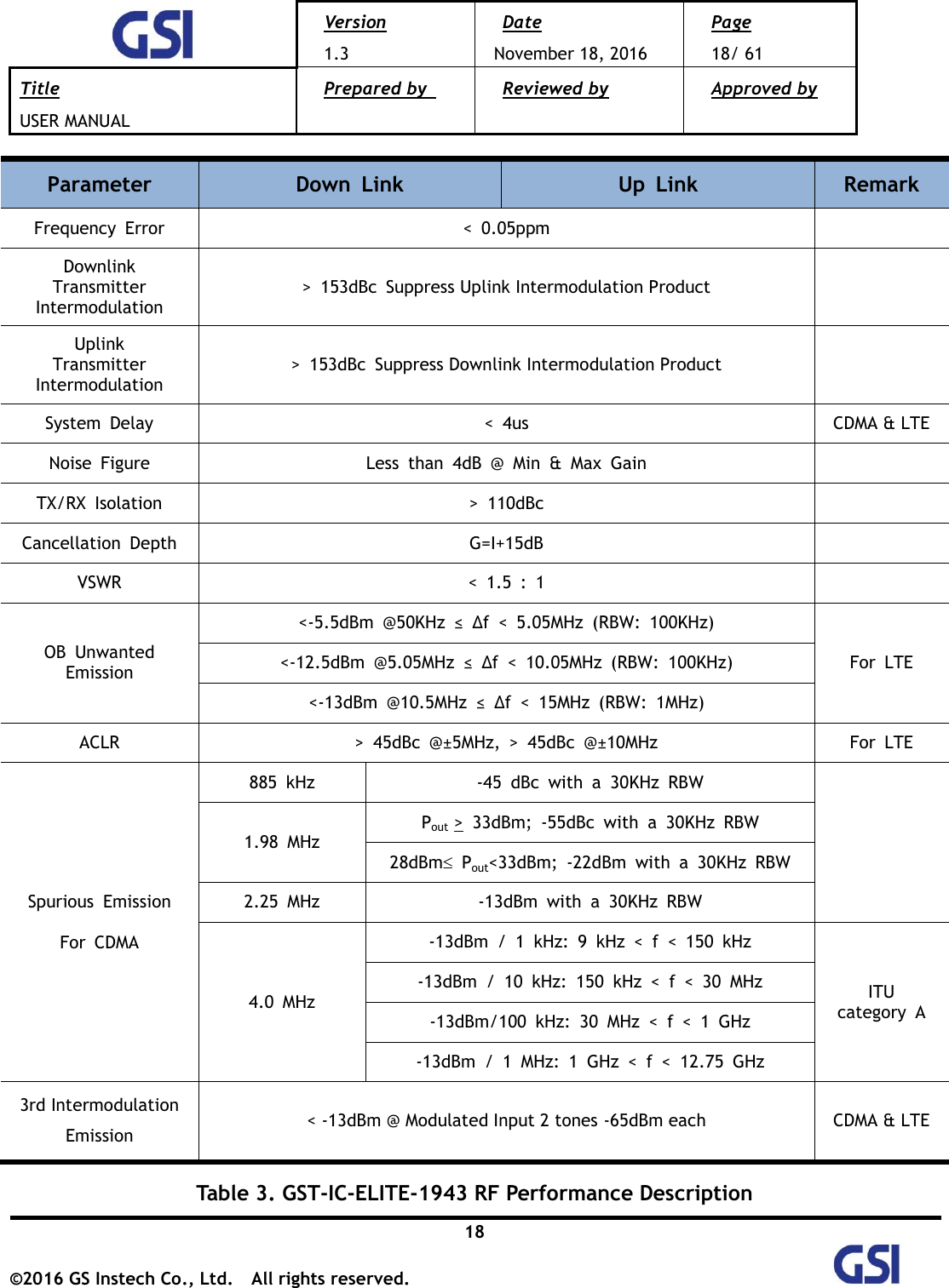
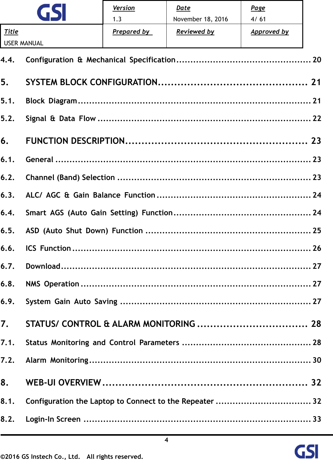
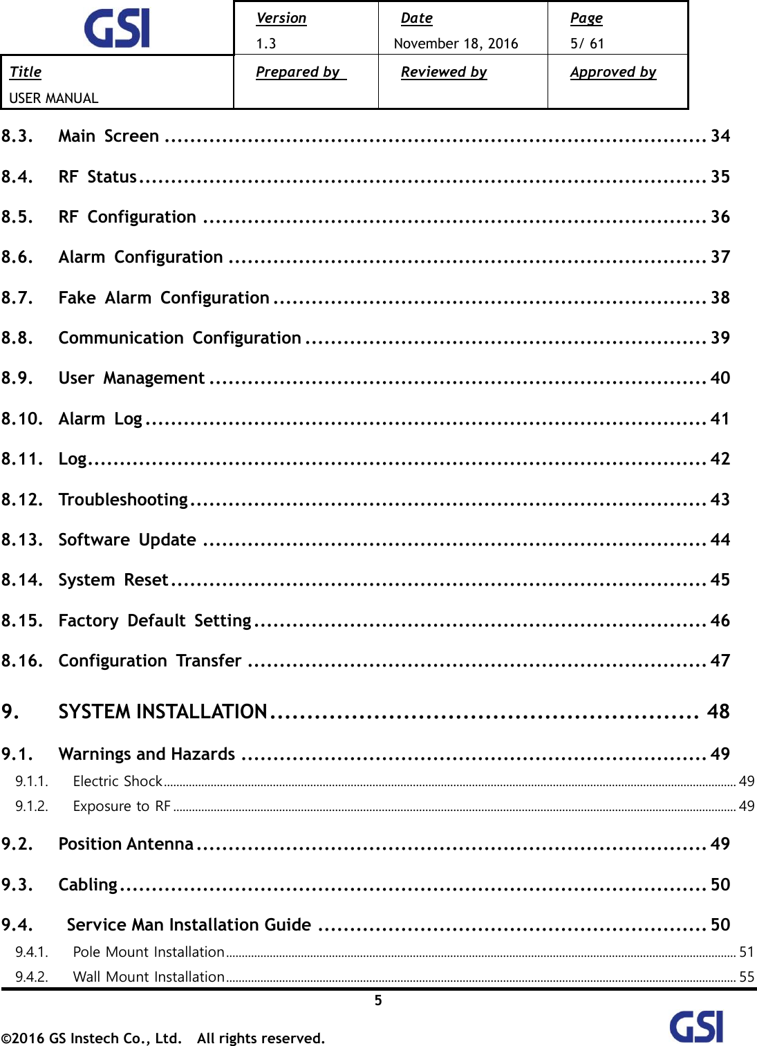
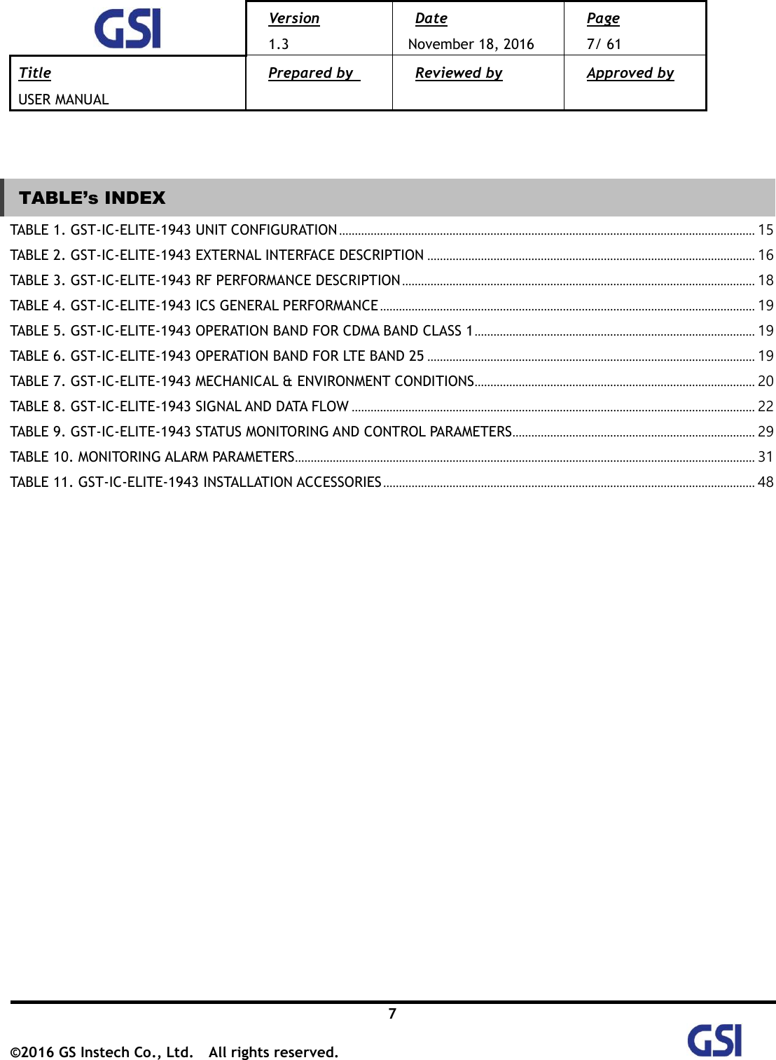
![Version 1.3 Date November 18, 2016 Page 3/ 61 Title USER MANUAL Prepared by Reviewed by Approved by 3 ©2016 GS Instech Co., Ltd. All rights reserved. [TABLE OF CONTENTS] CHAPTER’s INDEX 1. GENERAL ............................................................................ 8 1.1. Purpose ............................................................................................ 8 1.2. Copyright .......................................................................................... 8 1.3. FCC Warning Statements ....................................................................... 9 2. INTRODUCTION ................................................................... 11 2.1. System Overview ............................................................................... 11 2.2. Main Features ................................................................................... 12 3. SYSTEM DESIGN .................................................................. 13 3.1. Perspective View ............................................................................... 13 3.2. Exterior View ................................................................................... 14 3.3. Interior View .................................................................................... 15 3.4. External Interface .............................................................................. 16 4. SYSTEM SPECIFICATION ......................................................... 17 4.1. RF Performance ................................................................................ 17 4.2. ICS General Performance ..................................................................... 19 4.3. Frequency Information ....................................................................... 19 4.3.1. CDMA Band CLASS 1 ........................................................................................................................................................................ 19 4.3.2. LTE Band 25 ........................................................................................................................................................................................... 19](https://usermanual.wiki/GS-Instech/GSTICELITE1943/User-Guide-3205849-Page-3.png)
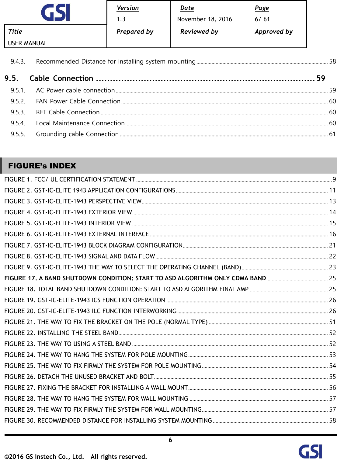
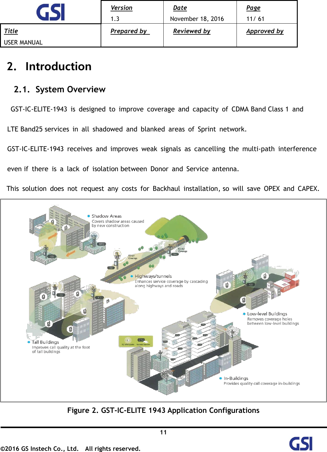
![Version 1.3 Date November 18, 2016 Page 14/ 61 Title USER MANUAL Prepared by Reviewed by Approved by 14 ©2016 GS Instech Co., Ltd. All rights reserved. 3.2. Exterior View Figure 4. GST-IC-ELITE-1943 Exterior View 7.8"(200mm) 13.2"(335mm) 19" (480mm) [Front View] [Bottom View] [Left View] [Right View] [Top View] [Rear View]](https://usermanual.wiki/GS-Instech/GSTICELITE1943/User-Guide-3205849-Page-14.png)