GS Instech GSTICELITE1943 LTE/CDMA ICS RF Repeater User Manual GST IC ELITE 1943 V1 3 Rev 1
GS Instech Co., Ltd. LTE/CDMA ICS RF Repeater GST IC ELITE 1943 V1 3 Rev 1
GST-IC-ELITE-1943_User Manual_V1.3_Rev.1

Version
1.3
Date
November 18, 2016
Page
1/ 61
Title
USER MANUAL
Prepared by
Reviewed by
Approved by
1
©2016 GS Instech Co., Ltd. All rights reserved.
GST-IC-ELITE-1943
USER MANUAL
November 18, 2016
GS Instech Co., Ltd.
Version
1.3
Date
November 18, 2016
Page
2/ 61
Title
USER MANUAL
Prepared by
Reviewed by
Approved by
2
©2016 GS Instech Co., Ltd. All rights reserved.
[CHANGE RECORD]
DATE
NAMES
DESCRIPTIONS
VERSION
REMARK
September 5, 2016
H.J.CHOI
Original Draft
1.0
September 23th, 2016
H.J.CHOI
Add a Modem redundant Configuration
1.1
November 11, 2016
H.J.CHOI
Change a Model Number
1.2
Edit contents
November 18, 2016
H.J.CHOI
Edit according to FCC/ UL Regulation
1.3

Version
1.3
Date
November 18, 2016
Page
3/ 61
Title
USER MANUAL
Prepared by
Reviewed by
Approved by
3
©2016 GS Instech Co., Ltd. All rights reserved.
[TABLE OF CONTENTS]
CHAPTER’s INDEX
1. GENERAL ............................................................................ 8
1.1. Purpose ............................................................................................ 8
1.2. Copyright .......................................................................................... 8
1.3. FCC Warning Statements ....................................................................... 9
2. INTRODUCTION ................................................................... 11
2.1. System Overview ............................................................................... 11
2.2. Main Features ................................................................................... 12
3. SYSTEM DESIGN .................................................................. 13
3.1. Perspective View ............................................................................... 13
3.2. Exterior View ................................................................................... 14
3.3. Interior View .................................................................................... 15
3.4. External Interface .............................................................................. 16
4. SYSTEM SPECIFICATION ......................................................... 17
4.1. RF Performance ................................................................................ 17
4.2. ICS General Performance ..................................................................... 19
4.3. Frequency Information ....................................................................... 19
4.3.1. CDMA Band CLASS 1 ........................................................................................................................................................................ 19
4.3.2. LTE Band 25 ........................................................................................................................................................................................... 19
Version
1.3
Date
November 18, 2016
Page
4/ 61
Title
USER MANUAL
Prepared by
Reviewed by
Approved by
4
©2016 GS Instech Co., Ltd. All rights reserved.
4.4. Configuration & Mechanical Specification ................................................ 20
5. SYSTEM BLOCK CONFIGURATION .............................................. 21
5.1. Block Diagram ................................................................................... 21
5.2. Signal & Data Flow ............................................................................ 22
6. FUNCTION DESCRIPTION ........................................................ 23
6.1. General ........................................................................................... 23
6.2. Channel (Band) Selection ..................................................................... 23
6.3. ALC/ AGC & Gain Balance Function ....................................................... 24
6.4. Smart AGS (Auto Gain Setting) Function ................................................. 24
6.5. ASD (Auto Shut Down) Function ........................................................... 25
6.6. ICS Function ..................................................................................... 26
6.7. Download ......................................................................................... 27
6.8. NMS Operation .................................................................................. 27
6.9. System Gain Auto Saving .................................................................... 27
7. STATUS/ CONTROL & ALARM MONITORING .................................. 28
7.1. Status Monitoring and Control Parameters .............................................. 28
7.2. Alarm Monitoring ............................................................................... 30
8. WEB-UI OVERVIEW ............................................................... 32
8.1. Configuration the Laptop to Connect to the Repeater .................................. 32
8.2. Login-In Screen ................................................................................. 33

Version
1.3
Date
November 18, 2016
Page
5/ 61
Title
USER MANUAL
Prepared by
Reviewed by
Approved by
5
©2016 GS Instech Co., Ltd. All rights reserved.
8.3. Main Screen ..................................................................................... 34
8.4. RF Status ......................................................................................... 35
8.5. RF Configuration ............................................................................... 36
8.6. Alarm Configuration ........................................................................... 37
8.7. Fake Alarm Configuration .................................................................... 38
8.8. Communication Configuration ............................................................... 39
8.9. User Management .............................................................................. 40
8.10. Alarm Log ........................................................................................ 41
8.11. Log ................................................................................................. 42
8.12. Troubleshooting ................................................................................. 43
8.13. Software Update ............................................................................... 44
8.14. System Reset .................................................................................... 45
8.15. Factory Default Setting ....................................................................... 46
8.16. Configuration Transfer ........................................................................ 47
9. SYSTEM INSTALLATION .......................................................... 48
9.1. Warnings and Hazards ......................................................................... 49
9.1.1. Electric Shock ........................................................................................................................................................................................ 49
9.1.2. Exposure to RF ..................................................................................................................................................................................... 49
9.2. Position Antenna ................................................................................ 49
9.3. Cabling ............................................................................................ 50
9.4. Service Man Installation Guide ............................................................. 50
9.4.1. Pole Mount Installation .................................................................................................................................................................... 51
9.4.2. Wall Mount Installation .................................................................................................................................................................... 55
Version
1.3
Date
November 18, 2016
Page
6/ 61
Title
USER MANUAL
Prepared by
Reviewed by
Approved by
6
©2016 GS Instech Co., Ltd. All rights reserved.
9.4.3. Recommended Distance for installing system mounting ................................................................................................ 58
9.5. Cable Connection .............................................................................. 59
9.5.1. AC Power cable connection ........................................................................................................................................................... 59
9.5.2. FAN Power Cable Connection ....................................................................................................................................................... 60
9.5.3. RET Cable Connection ...................................................................................................................................................................... 60
9.5.4. Local Maintenance Connection .................................................................................................................................................... 60
9.5.5. Grounding cable Connection ........................................................................................................................................................ 61
FIGURE’s INDEX
FIGURE 1. FCC/ UL CERTIFICATION STATEMENT ............................................................................................................................................... 9
FIGURE 2. GST-IC-ELITE 1943 APPLICATION CONFIGURATIONS ............................................................................................................... 11
FIGURE 3. GST-IC-ELITE-1943 PERSPECTIVE VIEW ........................................................................................................................................ 13
FIGURE 4. GST-IC-ELITE-1943 EXTERIOR VIEW............................................................................................................................................... 14
FIGURE 5. GST-IC-ELITE-1943 INTERIOR VIEW ............................................................................................................................................... 15
FIGURE 6. GST-IC-ELITE-1943 EXTERNAL INTERFACE .................................................................................................................................. 16
FIGURE 7. GST-IC-ELITE-1943 BLOCK DIAGRAM CONFIGURATION .......................................................................................................... 21
FIGURE 8. GST-IC-ELITE-1943 SIGNAL AND DATA FLOW .............................................................................................................................. 22
FIGURE 9. GST-IC-ELITE-1943 THE WAY TO SELECT THE OPERATING CHANNEL (BAND) ............................................................... 23
FIGURE 17. A BAND SHUTDOWN CONDITION: START TO ASD ALGORITHM ONLY CDMA BAND ............................................. 25
FIGURE 18. TOTAL BAND SHUTDOWN CONDITION: START TO ASD ALGORITHM FINAL AMP ......................................................... 25
FIGURE 19. GST-IC-ELITE-1943 ICS FUNCTION OPERATION ...................................................................................................................... 26
FIGURE 20. GST-IC-ELITE-1943 ILC FUNCTION INTERWORKING .............................................................................................................. 26
FIGURE 21. THE WAY TO FIX THE BRACKET ON THE POLE (NORMAL TYPE) ....................................................................................... 51
FIGURE 22. INSTALLING THE STEEL BAND ......................................................................................................................................................... 52
FIGURE 23. THE WAY TO USING A STEEL BAND ............................................................................................................................................... 52
FIGURE 24. THE WAY TO HANG THE SYSTEM FOR POLE MOUNTING ...................................................................................................... 53
FIGURE 25. THE WAY TO FIX FIRMLY THE SYSTEM FOR POLE MOUNTING ............................................................................................ 54
FIGURE 26. DETACH THE UNUSED BRACKET AND BOLT ............................................................................................................................... 55
FIGURE 27. FIXING THE BRACKET FOR INSTALLING A WALL MOUNT ...................................................................................................... 56
FIGURE 28. THE WAY TO HANG THE SYSTEM FOR WALL MOUNTING ..................................................................................................... 57
FIGURE 29. THE WAY TO FIX FIRMLY THE SYSTEM FOR WALL MOUNTING ............................................................................................ 57
FIGURE 30. RECOMMENDED DISTANCE FOR INSTALLING SYSTEM MOUNTING .................................................................................... 58
Version
1.3
Date
November 18, 2016
Page
7/ 61
Title
USER MANUAL
Prepared by
Reviewed by
Approved by
7
©2016 GS Instech Co., Ltd. All rights reserved.
TABLE’s INDEX
TABLE 1. GST-IC-ELITE-1943 UNIT CONFIGURATION .................................................................................................................................... 15
TABLE 2. GST-IC-ELITE-1943 EXTERNAL INTERFACE DESCRIPTION ........................................................................................................ 16
TABLE 3. GST-IC-ELITE-1943 RF PERFORMANCE DESCRIPTION ................................................................................................................ 18
TABLE 4. GST-IC-ELITE-1943 ICS GENERAL PERFORMANCE ....................................................................................................................... 19
TABLE 5. GST-IC-ELITE-1943 OPERATION BAND FOR CDMA BAND CLASS 1 ......................................................................................... 19
TABLE 6. GST-IC-ELITE-1943 OPERATION BAND FOR LTE BAND 25 ........................................................................................................ 19
TABLE 7. GST-IC-ELITE-1943 MECHANICAL & ENVIRONMENT CONDITIONS ......................................................................................... 20
TABLE 8. GST-IC-ELITE-1943 SIGNAL AND DATA FLOW ................................................................................................................................ 22
TABLE 9. GST-IC-ELITE-1943 STATUS MONITORING AND CONTROL PARAMETERS ............................................................................. 29
TABLE 10. MONITORING ALARM PARAMETERS.................................................................................................................................................. 31
TABLE 11. GST-IC-ELITE-1943 INSTALLATION ACCESSORIES ...................................................................................................................... 48

Version
1.3
Date
November 18, 2016
Page
8/ 61
Title
USER MANUAL
Prepared by
Reviewed by
Approved by
8
©2016 GS Instech Co., Ltd. All rights reserved.
1. General
1.1. Purpose
This document introduces features, specifications, structures and operation guideline for
the GST-IC-ELITE-1943 CDMA & LTE Repeater
1.2. Copyright
All text and image in this document are subject to the copyright of GS Instech Co., Ltd.
This document may not be reproduced, distributed, or modified without the written permission of
GS Instech Co., Ltd.
Version
1.3
Date
November 18, 2016
Page
9/ 61
Title
USER MANUAL
Prepared by
Reviewed by
Approved by
9
©2016 GS Instech Co., Ltd. All rights reserved.
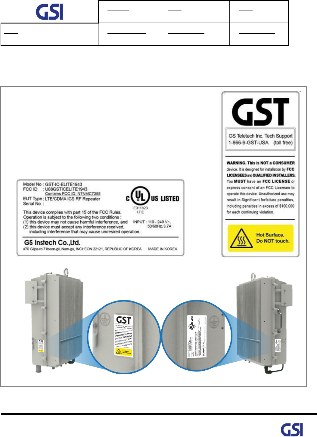
1.3. FCC Warning Statements
FCC Warning Statement for system is follows. Must attach the label under manufacturing.
Figure 1. FCC/ UL Certification Statement

Version
1.3
Date
November 18, 2016
Page
10/ 61
Title
USER MANUAL
Prepared by
Reviewed by
Approved by
10
©2016 GS Instech Co., Ltd. All rights reserved.
FCC Part 15.105 statement (Class A)
This equipment has been tested and found to comply with the limits for a Class A digital device, pursuant
to part 15 of the FCC Rules. These limits are designed to provide reasonable protection against harmful
interference when the equipment is operated in a commercial environment. This equipment generates,
uses, and can radiate radio frequency energy and, if not installed and used in accordance with the
instruction manual, may cause harmful interference to radio communications. Operation of this
equipment in a residential area is likely to cause harmful interference in which case the user will be
required to correct the interference at his own expense.
FCC Part 15.21 statement
Any changes or modifications not expressly approved by the party responsible for compliance
could void the user's authority to operate this equipment.
Home/ personal use are prohibited
Use of unauthorized antennas, cables, and/or coupling devices not conforming with
ERP/EIRP and/or indoor‐only restrictions is prohibited

Version
1.3
Date
November 18, 2016
Page
11/ 61
Title
USER MANUAL
Prepared by
Reviewed by
Approved by
11
©2016 GS Instech Co., Ltd. All rights reserved.
2. Introduction
2.1. System Overview
GST-IC-ELITE-1943 is designed to improve coverage and capacity of CDMA Band Class 1 and
LTE Band25 services in all shadowed and blanked areas of Sprint network.
GST-IC-ELITE-1943 receives and improves weak signals as cancelling the multi-path interference
even if there is a lack of isolation between Donor and Service antenna.
This solution does not request any costs for Backhaul installation, so will save OPEX and CAPEX.
Figure 2. GST-IC-ELITE 1943 Application Configurations

Version
1.3
Date
November 18, 2016
Page
12/ 61
Title
USER MANUAL
Prepared by
Reviewed by
Approved by
12
©2016 GS Instech Co., Ltd. All rights reserved.
2.2. Main Features
• Maintain the Quality of Demodulation performance on the Overlay-Cell Region using Delay-Reduction
Technology ( Less than 4us for CDMA & LTE)
• Provide the SNMP Solution
• Ensure the Uplink-Sensitivity and Suppress Rising-UL noise floor under high out-power at Downlink
using PIMD-Reduction Technology ( Less than 153dBc)
• Excellent RF Specifications
- High Gain: more than 105dB
- Low Noise figure under all system gain condition: Less than 4dB
- Grate Performance of Interference Cancellation: G=I+15dB
- High Rejection: More than -50dBc at Band Edge ± 450 KHz
• Adaptable functions for Operation
- RS (Pilot) Aware, Smart ALC & ASD, Attenuator for each Band
- Total Bandwidth of 25MHz Configurable in 1.25MHz Step for CDMA up to 15MHz and
5MHz Step for LTE up to 10MHz
• Complies with NEMA 4 (equal to IP66) for Outdoor application
• Apply for Cascade 6 chain installation
• FCC Part 24, Part 15B class A
• UL 60950-1, 60950-22 certificated

Version
1.3
Date
November 18, 2016
Page
13/ 61
Title
USER MANUAL
Prepared by
Reviewed by
Approved by
13
©2016 GS Instech Co., Ltd. All rights reserved.
3. System Design
3.1. Perspective View
Figure 3. GST-IC-ELITE-1943 Perspective View
Locking Bolt
FAN Connector
FAN
Installation Bracket
Handle for carrying
FAN Cable

Version
1.3
Date
November 18, 2016
Page
14/ 61
Title
USER MANUAL
Prepared by
Reviewed by
Approved by
14
©2016 GS Instech Co., Ltd. All rights reserved.
3.2. Exterior View
Figure 4. GST-IC-ELITE-1943 Exterior View
7.8"(200mm)
13.2"(335mm)
19" (480mm)
[Front View]
[Bottom View]
[Left View]
[Right View]
[Top View]
[Rear View]
Version
1.3
Date
November 18, 2016
Page
15/ 61
Title
USER MANUAL
Prepared by
Reviewed by
Approved by
15
©2016 GS Instech Co., Ltd. All rights reserved.
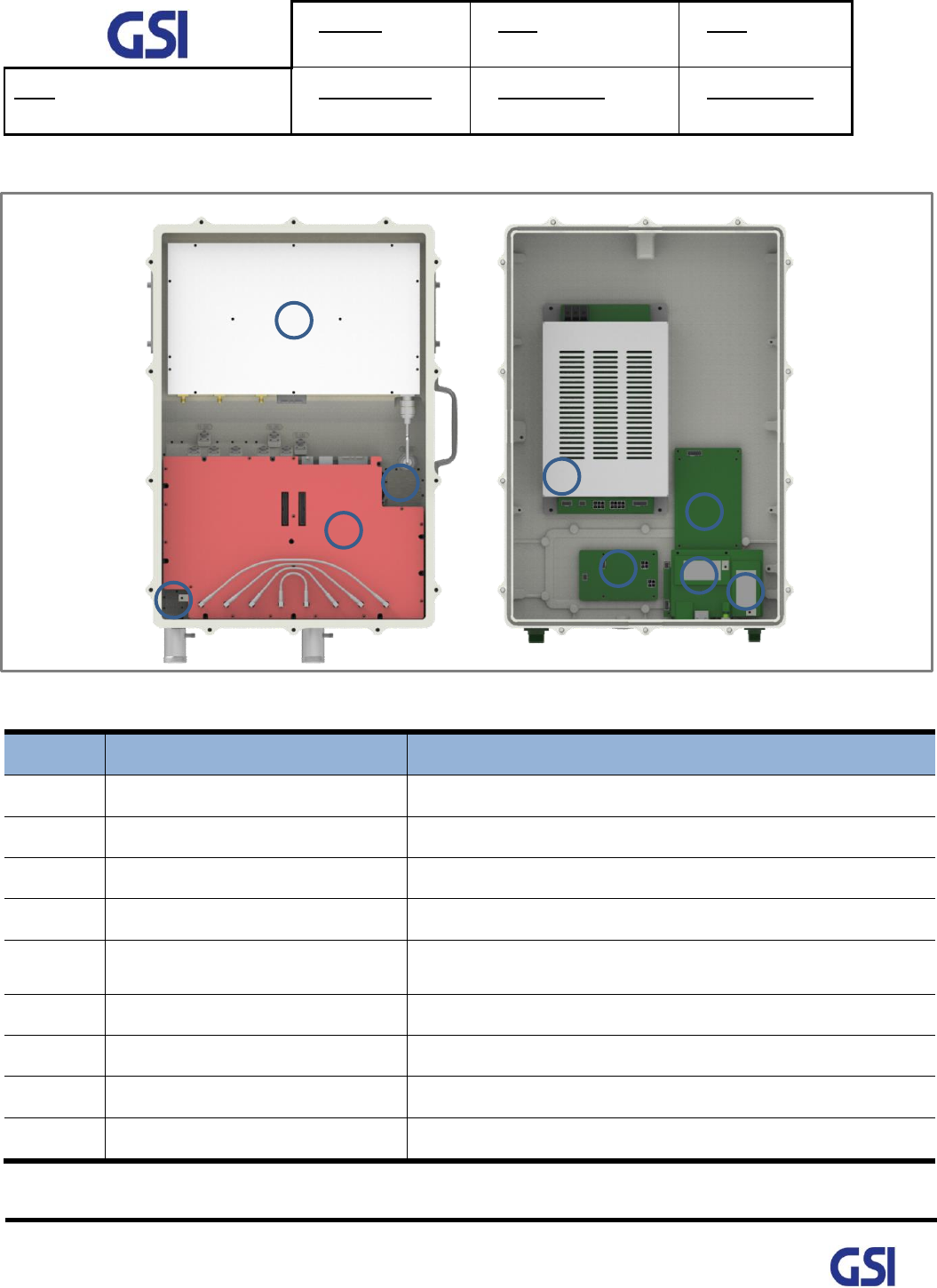
3.3. Interior View
Figure 5. GST-IC-ELITE-1943 Interior View
No
Name
Remark
1
Power Supply Unit
Input: 110Vac~240Vac/ Output (DC):+32V, 24V, 5.6V
2
SNMP Board
For EMS using Wireless Modem
3
Surge Protect Board
RET Surge Protection
4
High Power Amplifier
For generating High RF Power
5
ICM
(Interference Cancellation Module)
Contains RF Up & Down Convertor, Digital Signal Processing
and Controller Unit
6
Duplexer
Separate Downlink and Uplink Frequency Band
7
Modem Coupling Port
Connect the Wireless Modem Output
8
LTE Modem
For Status Monitoring and Control from Server
9
CDMA Modem
For Status Monitoring and Control from Server
Table 1. GST-IC-ELITE-1943 Unit Configuration
1
2
3
4
5
6
7
8
9

Version
1.3
Date
November 18, 2016
Page
16/ 61
Title
USER MANUAL
Prepared by
Reviewed by
Approved by
16
©2016 GS Instech Co., Ltd. All rights reserved.
3.4. External Interface
Figure 6. GST-IC-ELITE-1943 External Interface
No
NAMES
DESCRIPTION
SPECIFICATION
1
AC IN
AC Power Input Port
MS-3102A-10SL-3P
2
RJ-45 & SIM
CARD SLOT
Local Maintenance & Modem Activation
Local: RJ-45
SLOT: AUSIM-115AADA0-R02
3
RET
Remote Antenna Control Port (AISG 2.0)
SU20SPR-8S/ 29V_1.5A max
4
FAN
FAN Power & Alarm Connection
MS3102A14S-2P
5
Donor ANT
Donor Antenna Connection
7/16 DIN Female with 30dB Coupler
6
Service ANT
Service Antenna Connection
7/16 DIN Female with 30dB Coupler
7
LED
System Total Alarm Indication
General Performance
8
Vent-Core
Maintain Humidity & Temp Inside
IP66
Table 2. GST-IC-ELITE-1943 External Interface Description
1
2
3
4
5
AC IN
RET
FAN
DONOR ANT
SERVICE ANT
7
6
8

Version
1.3
Date
November 18, 2016
Page
17/ 61
Title
USER MANUAL
Prepared by
Reviewed by
Approved by
17
©2016 GS Instech Co., Ltd. All rights reserved.
4. System Specification
4.1. RF Performance
Parameter
Down Link
Up Link
Remark
Frequency Range
1930MHz ~ 1995MHz
1850MHz ~ 1915MHz
Input Range
-62dBm ~ -32dBm/ Total
-75dBm ~ -45dBm/ Total
Output Power
+43dBm (20W) max.
CDMA 10W+LTE 10W / Total
+30dBm (1W) max.
Channel Capacity
【CDMA】 15MHz max/ 1.25MHz Step
【LTE】 10MHz max (9.01MHz for OBW)/ 5MHz Step
Gain
Range
65dB ~ 105dB (Max 40dB)
ALC: 30dB
Manual: 10dB
Adjust Step
0.5dB
Accuracy
±0.5dB
Ripple
±1.5dB p-p
Roll off
> 50dBc @ Channel OBW ±450KHz
> 50dBc @ Channel OBW ±1MHz
> 75dBc @ Channel OBW ±3.5MHz
Waveform Quality
No Feedback & Max/ Min Input
≥ 0.99 (Rho)
For CDMA
G=I+15dB & Fading 10Hz G=I
≥ 0.95 (Rho)
EVM
No Feedback & Max/ Min Input
QPSK
7.1%
For LTE
16QAM
5.1%
64QAM
3.2%
G=I+15dB & Fading 10Hz G=I
QPSK
8%
16QAM
64QAM

Version
1.3
Date
November 18, 2016
Page
18/ 61
Title
USER MANUAL
Prepared by
Reviewed by
Approved by
18
©2016 GS Instech Co., Ltd. All rights reserved.
Parameter
Down Link
Up Link
Remark
Frequency Error
< 0.05ppm
Downlink
Transmitter
Intermodulation
> 153dBc Suppress Uplink Intermodulation Product
Uplink
Transmitter
Intermodulation
> 153dBc Suppress Downlink Intermodulation Product
System Delay
< 4us
CDMA & LTE
Noise Figure
Less than 4dB @ Min & Max Gain
TX/RX Isolation
> 110dBc
Cancellation Depth
G=I+15dB
VSWR
< 1.5 : 1
OB Unwanted
Emission
<-5.5dBm @50KHz ≤ ∆f < 5.05MHz (RBW: 100KHz)
For LTE
<-12.5dBm @5.05MHz ≤ ∆f < 10.05MHz (RBW: 100KHz)
<-13dBm @10.5MHz ≤ ∆f < 15MHz (RBW: 1MHz)
ACLR
> 45dBc @±5MHz, > 45dBc @±10MHz
For LTE
Spurious Emission
For CDMA
885 kHz
-45 dBc with a 30KHz RBW
1.98 MHz
Pout > 33dBm; -55dBc with a 30KHz RBW
28dBm Pout<33dBm; -22dBm with a 30KHz RBW
2.25 MHz
-13dBm with a 30KHz RBW
4.0 MHz
-13dBm / 1 kHz: 9 kHz < f < 150 kHz
ITU
category A
-13dBm / 10 kHz: 150 kHz < f < 30 MHz
-13dBm/100 kHz: 30 MHz < f < 1 GHz
-13dBm / 1 MHz: 1 GHz < f < 12.75 GHz
3rd Intermodulation
Emission
< -13dBm @ Modulated Input 2 tones -65dBm each
CDMA & LTE
Table 3. GST-IC-ELITE-1943 RF Performance Description
Version
1.3
Date
November 18, 2016
Page
19/ 61
Title
USER MANUAL
Prepared by
Reviewed by
Approved by
19
©2016 GS Instech Co., Ltd. All rights reserved.
4.2. ICS General Performance
No.
Parameter
Condition
Specification
1
Gain Re-Tracking Time after reset
Target Gain ±1dB
< 10 Sec
2
Isolation Sensing Range
-10dB < Gain < 10dB
-20dB < Gain < 20dB
Accuracy ±1
Accuracy ±3
3
G = I + 15dB
Static
General Operating
4
G = I
10Hz
Fast Fading
Table 4. GST-IC-ELITE-1943 ICS General Performance
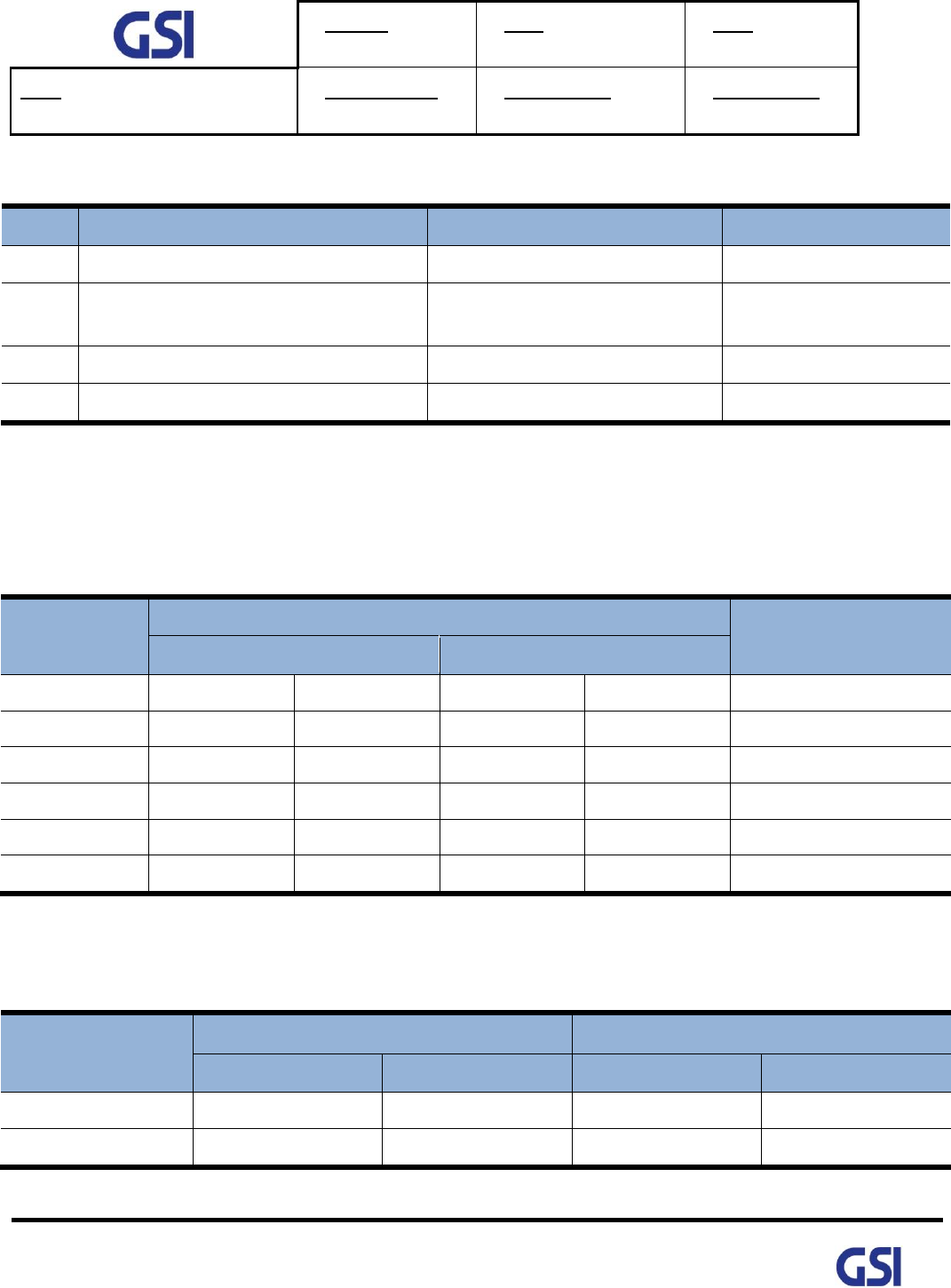
4.3. Frequency Information
4.3.1. CDMA Band CLASS 1
Block
Transmit frequency band (MHz)
Bandwidth
UL / DL
Uplink
Downlink
A
1850
1865
1930
1945
15
D
1865
1870
1945
1950
5
B
1870
1885
1950
1965
15
E
1885
1890
1965
1970
5
F
1890
1895
1970
1975
5
C
1895
1910
1975
1990
15
Table 5. GST-IC-ELITE-1943 Operation Band for CDMA Band Class 1
4.3.2. LTE Band 25
BW
ERAFCN (Count 1 step)
Center Frequency (100KHz step)
Start
Stop
Start(MHz)
Stop(MHz)
5MHz
8065
8665
1932.5
1992.5
10MHz
8090
8640
1935
1990
Table 6. GST-IC-ELITE-1943 Operation Band for LTE Band 25
Version
1.3
Date
November 18, 2016
Page
20/ 61
Title
USER MANUAL
Prepared by
Reviewed by
Approved by
20
©2016 GS Instech Co., Ltd. All rights reserved.
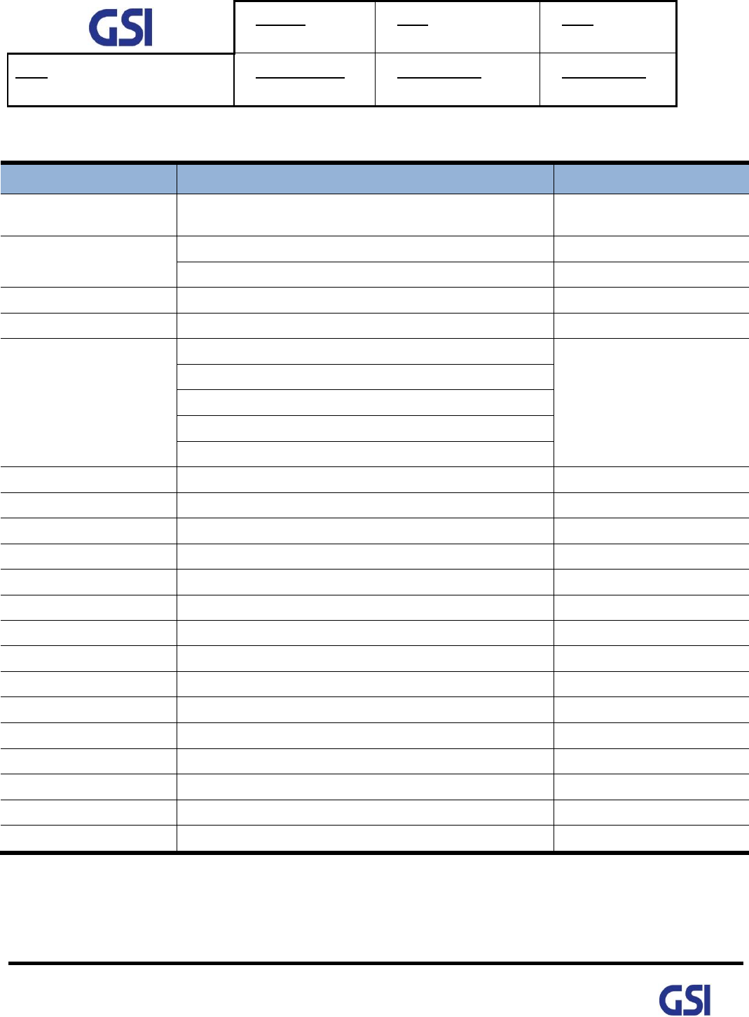
4.4. Configuration & Mechanical Specification
Parameter
Specification
Remark
Donor/ Service
Antenna Filter
One Output port-duplex type for LTE & CDMA
Donor Duplexer include
Modem ANT port
Power Supply
AC Input Voltage: 110~240V (50/60Hz)
3.7A max
DC Output Voltage: 32V/ 24V/ 5.6V
Operation Temperature
-40°C~+55°C (100%RH)
Storage Temperature
-40°C~+85°C (5~95%RH)
Connectors
Antenna: 7/16 DIN Female
On Bottom side
Ethernet: RJ-45
AC: MS-3102A10SL-3P
FAN: MS-3102A14S-2P
RET: SU20SPR
Size
19" x 13.2" x 7.8"(480mm x 335mm x 200mm)
Without Bracket
Weigh
Less than 25kg (55.1lb)
Without Bracket
Power Consumption
Less than 350W
MTBF
100,000 hours or higher
Internal Modem
LTE Modem primary
Back up with CDMA Modem
RET
Provide a physical Connection & 29V/1.5Amax
AISG 2.0 Standard
Dust Resistance
Telcordia GR63-CORE
Vibration Resistance
1G, 10~150Hz, 0.1 Octaves/min
Grounding
nonferrous metal and anchoring point on bottom side
For RF and power cabling
Environmental Spec.
NEMA4
IP 66
Sustained winds.
150mph
Altitude
AMSL 10,000ft
Mount Application
Metal or Wooden Poles
8"-20" outside diameter
Pollution degree
PD2
Overvoltage Category
OVC II
Table 7. GST-IC-ELITE-1943 Mechanical & Environment conditions

Version
1.3
Date
November 18, 2016
Page
21/ 61
Title
USER MANUAL
Prepared by
Reviewed by
Approved by
21
©2016 GS Instech Co., Ltd. All rights reserved.
5. System Block Configuration
5.1. Block Diagram
Figure 7. GST-IC-ELITE-1943 Block Diagram Configuration
The repeater improves service in the Sprint Network of CDMA Class 1 & LTE Band 25.
User may select frequency band according to the site peculiarities.
After receiving a weak signal from Donor antenna, the repeater improves and sends securely isolated
signal out to service antenna under lack of isolation between Donor and Service Antenna using
the ICS (Interference-Cancellation-System) engine.
The Repeater is consists of a ICM (Down and up converters with Digital Signal Processing (DSP) module),
Cavity filters and power amplifier. In Downlink Path, a weak RF signal is received from Donor Antenna.
being converted from RF to IF signal, It is transferred to the DSP&ICS block, where after digitalizing by
DA converter, signal is filtered by DSP. After filtering digital signal is converted into analog RF signal
via modulator and then transmitted to amplifier. Desirable signal is amplified and outputted through
Service Antenna. Uplink path works vice versa.
Version
1.3
Date
November 18, 2016
Page
22/ 61
Title
USER MANUAL
Prepared by
Reviewed by
Approved by
22
©2016 GS Instech Co., Ltd. All rights reserved.
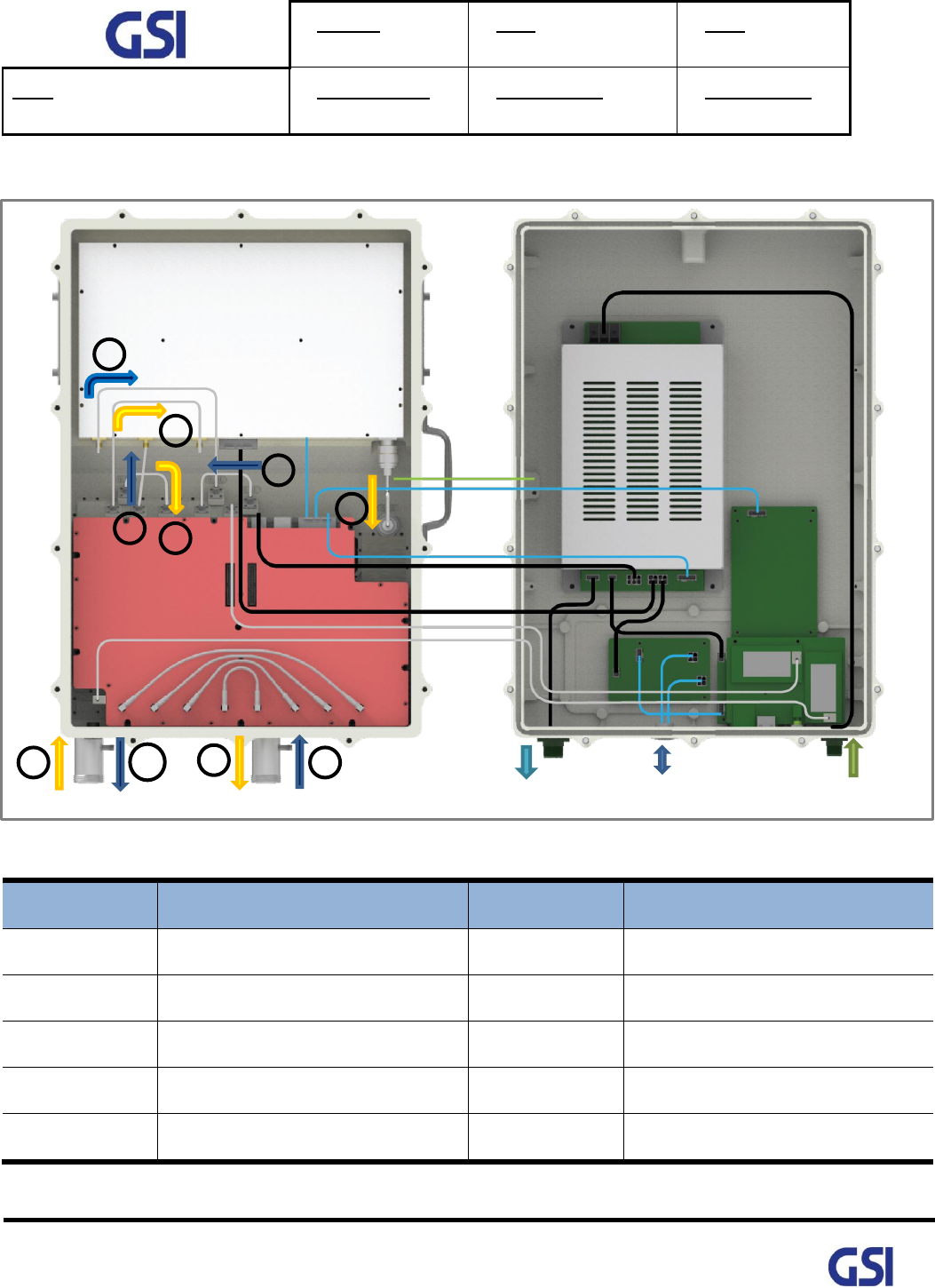
5.2. Signal & Data Flow
Figure 8. GST-IC-ELITE-1943 Signal and Data Flow
Table 8. GST-IC-ELITE-1943 Signal and Data Flow
No
Signal Flow
No
Signal Flow
1-DL
From Donor Antenna
6-UL
From Service Antenna
2-DL
Donor Duplexer ICM-DNC IN
7-UL
Service Duplexer ICM-DNC IN
3-DL
ICM-UPC OUT AMP-IN
8-UL
ICM-UPC OUT AMP-IN
4-DL
AMP-OUT Service Duplexer
9-UL
AMP-OUT Donor Duplexer
5-DL
To Service Antenna
10-UL
To Donor Antenna
1
2
3
4
5
6
7
8
9
10
Insert AC
Supply DC for FAN (+24V)
+24Vdc
ICM Control
+5.6Vdc
AMP Control
RET Control
+32Vdc
PSU signal
+5.6Vdc
+32Vdc
CDMA Modem
LTE Modem
LTE Modem
CDMA
Modem
Version
1.3
Date
November 18, 2016
Page
23/ 61
Title
USER MANUAL
Prepared by
Reviewed by
Approved by
23
©2016 GS Instech Co., Ltd. All rights reserved.
6. Function Description
6.1. General
• Ability to perform a function about management & operation (Band independently)
- Gain & Level Adjustment
- Smart AGS, ASD, ALC, Gain Balance, Channel Selection
• ILC operation based on ICS function
• Ability to initialize the entire system (include with local & remote control)
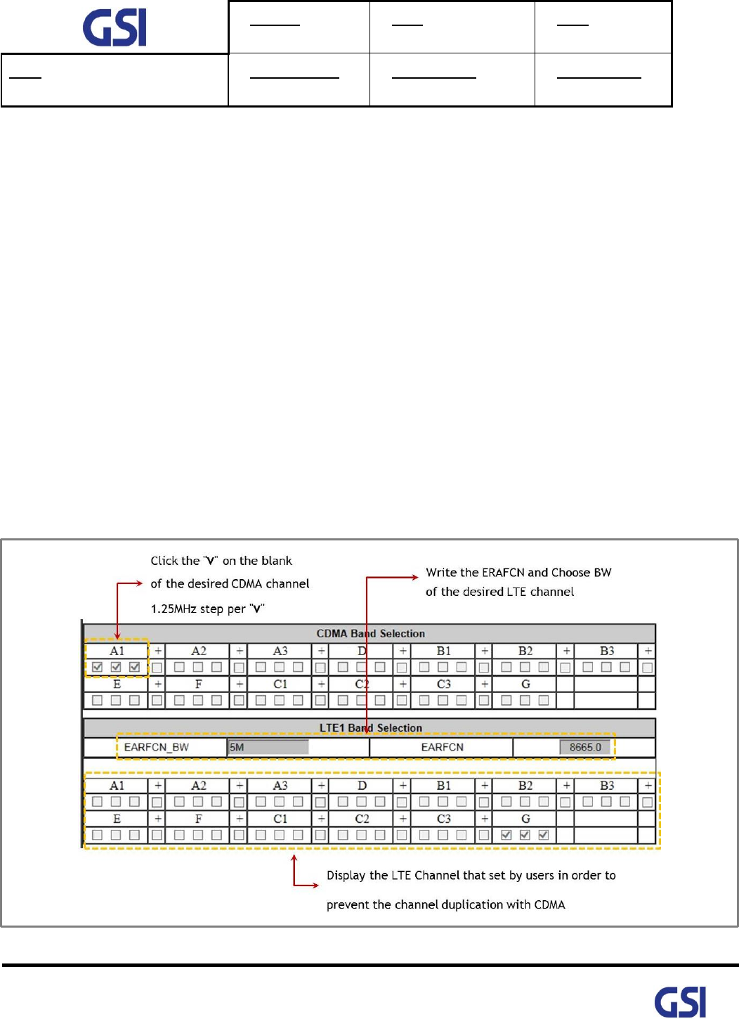
6.2. Channel (Band) Selection
• Repeater support the capacity of CDMA Band Class 1 and LTE Band 25
• Ability to set the 2 Non-Contiguous channel
• Support the CDMA 15MHz max per 1.25 step and LTE 10MHz max per 5MHz step
• User can set the desired channel using the Web-UI
Figure 9. GST-Ic-ELITE-1943 The way to select the operating Channel (Band)

Version
1.3
Date
November 18, 2016
Page
24/ 61
Title
USER MANUAL
Prepared by
Reviewed by
Approved by
24
©2016 GS Instech Co., Ltd. All rights reserved.
6.3. ALC/ AGC & Gain Balance Function
ALC means a function which controls gain automatically in order to protect H/W in case of
excessive out power more than user-defined threshold value upon Input RSSI change,
and to keep signal quality. AGC means UL Gain Balancing function based on DL Gain.
6.4. Smart AGS (Auto Gain Setting) Function
• Transmit the stable CDMA Pilot Power and LTE RS Power to use Smart ALC and CDMA/ LTE
Dual Modem
• Operate the BTS Coverage reliably
• Set the repeater gain correctly based on Path loss between BTS and Repeater, minimize the
increment of BTS Noise Floor
• If AGS function is close, system operate only Smart ALC function (able to control thru Web-UI)
Version
1.3
Date
November 18, 2016
Page
25/ 61
Title
USER MANUAL
Prepared by
Reviewed by
Approved by
25
©2016 GS Instech Co., Ltd. All rights reserved.
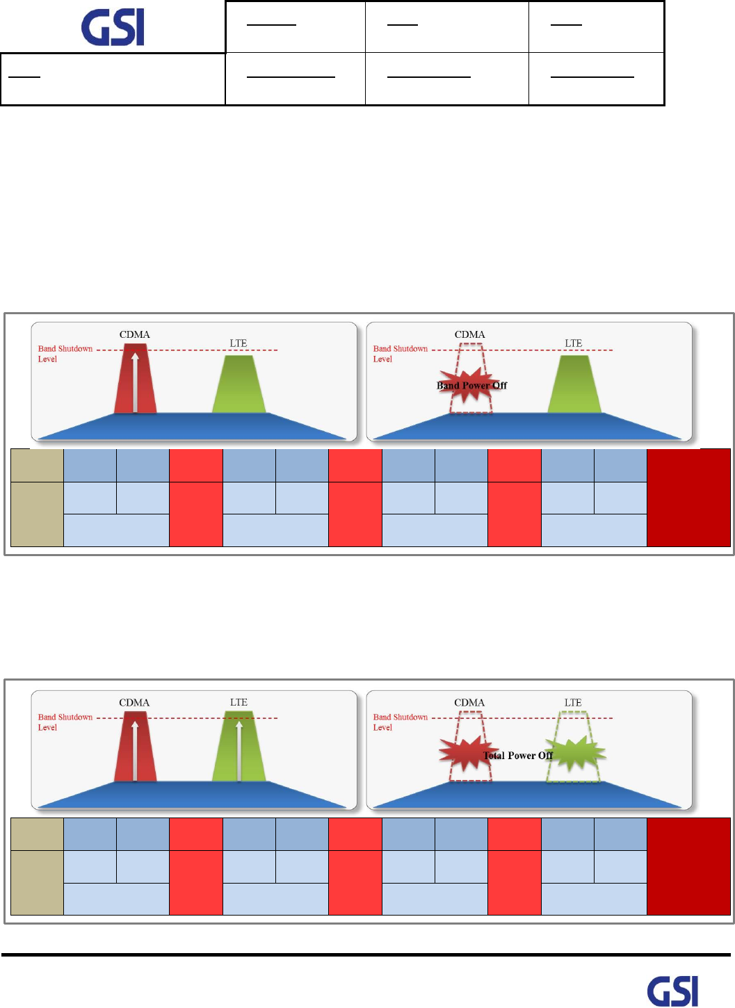
6.5. ASD (Auto Shut Down) Function
• Cut off the Output power automatically to prevent a damage if system output power too high
• Able to function On/Off thru Web-UI
• Operate band independently
• In Case of Only One-Band Algorithm
- Based on Band Output power
- Cut Off the Band Output power thru Digital Filter closing
Delay
Alarm
Check
Shut
Down
Alarm
Check
Shut
Down
Alarm
Check
Shut
Down
Alarm
Check
Permanent
Shut Down
5Min
3sec
1sec
20sec
10sec
1sec
20sec
10sec
1sec
10Min
10sec
1sec
4sec
11sec
11sec
11sec
Figure 10. A band Shutdown Condition: Start to ASD Algorithm only CDMA Band
• In Case of Total-Band Algorithm
- Based on Total Output Power
- Cut off the Total Output Power thru Final AMP Off
Delay
Alarm
Check
Shut
Down
Alarm
Check
Shut
Down
Alarm
Check
Shut
Down
Alarm
Check
Permanent
Shut Down
5Min
3sec
1sec
20sec
10sec
1sec
20sec
10sec
1sec
30Min
10sec
1sec
4sec
11sec
11sec
11sec
Figure 11. Total band Shutdown Condition: Start to ASD Algorithm Final AMP
Version
1.3
Date
November 18, 2016
Page
26/ 61
Title
USER MANUAL
Prepared by
Reviewed by
Approved by
26
©2016 GS Instech Co., Ltd. All rights reserved.
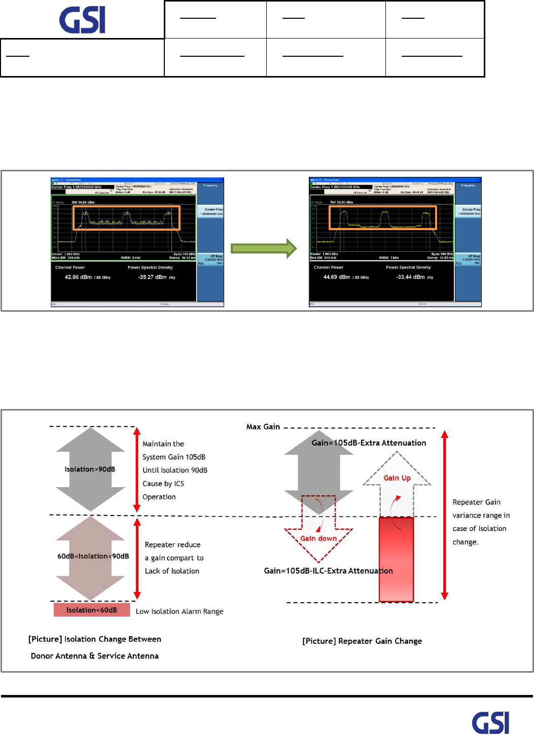
6.6. ICS Function
• Provide an Ability to operate stable under lack of isolation between Donor antenna and
Service antenna
- In case of operating under Repeater Gain=105dB, Antenna Isolation=90dB
Figure 12. GST-IC-ELITE-1943 ICS Function Operation
• ILC Function Interworking
- In case of "90dB<Isolation", Repeater reduce the gain compare to Isolation
- Repeater total Gain=Repeater Max Gain (105dB)-ILC-Extra Attenuation (ALC, Manual etc.)
Figure 13. GST-IC-ELITE-1943 ILC Function Interworking
ICS function
ON

Version
1.3
Date
November 18, 2016
Page
27/ 61
Title
USER MANUAL
Prepared by
Reviewed by
Approved by
27
©2016 GS Instech Co., Ltd. All rights reserved.
6.7. Download
• To changed and updated features of system operation and monitoring program
- Upgrade software or install a patch with minimal loss of service
(Less than 2mins except for FPGA Program)
- To handle a full software load and to receive/ error-check at the same time
- If the load is rendered unsatisfactory after the upload, it will automatically revert
to the old software load
6.8. NMS Operation
• Fault diagnostics and maintenance features can be available both through the Sprint proprietary
Network
• Management System (NMS) and locally at the Outdoor Repeater via Local Craft Terminal (LCT)
• All functions that can be performed at the local craft port (physical device) are available thru the
remote interface
• All configuration screens at the local craft port physical device location appear identically at the
remote location
6.9. System Gain Auto Saving
• Save the System Gain according to period for preparing the Power-Off or Reset
• In case of the Repeater is turned off or Reset, Support to re-optimize the system using saved
gain as soon as possible

Version
1.3
Date
November 18, 2016
Page
28/ 61
Title
USER MANUAL
Prepared by
Reviewed by
Approved by
28
©2016 GS Instech Co., Ltd. All rights reserved.
7. Status/ Control & Alarm Monitoring
7.1. Status Monitoring and Control Parameters
• In case of control parameter, present status but also setting value display on Web-UI.
Parameter
Status
Control
Description
Downlink
RSSI
○
A separate display according to CDMA<E
Output
○
A separate display according to CDMA<E
System Gain
○
A separate display according to CDMA<E
ALC
○
Set the ALC function On/Off
ALC Low Limit
○
Set the ALC Low Limit Value
Path On/Off
○
Decide to cut off CDMA & LTE
Attenuation
○
In order to adjust system gain,
set the attenuation value
Isolation (Unit: dB)
○
Display the isolation value between
Donor antenna and Service antenna
Band Selection
○
Select the band that user want to operate
Final AMP
○
Set the High Power final AMP On/Off
ASD
○
Set the Auto Shutdown function On/Off
Uplink
RSSI
○
A separate display according to CDMA<E
Output
○
A separate display according to CDMA<E
System Gain
○
A separate display according to CDMA<E
ALC
○
Set the ALC function On/Off
ALC Low Limit
○
Set the ALC Low Limit Value
Path On/Off
○
Decide to cut off CDMA<E
Attenuation
○
In order to adjust system gain,
set the attenuation value
Uplink
Isolation (Unit: dB)
○
Display the isolation value between
Donor antenna and Service antenna
Gain Balance
○
Select the band that user want to operate
& Set the Offset Value
Final AMP
○
Set the High Power final AMP On/Off
Version
1.3
Date
November 18, 2016
Page
29/ 61
Title
USER MANUAL
Prepared by
Reviewed by
Approved by
29
©2016 GS Instech Co., Ltd. All rights reserved.
Parameter
Status
Control
Description
ASD
○
Set the Auto Shutdown function On/Off
Common
ICM Version
○
Display a ICM Software Version
DL/UL FPGA Version
○
Display a DL/UL FPGA Software Version
Final AMP Version
○
Display a Final AMP Software Version
Site ID
○
Write the location Info. that install a repeater
System Serial Number
○
Write a System Serial Number
ICM Serial Number
○
Display a ICM Serial Number
Final AMP Serial Number
○
Display a Final AMP Serial Number
SNMP Serial Number
○
Write SNMP Serial Number
System Temperature
○
○
Display a present temperature inside a repeater
Set the temperature high limit value
Alarm Delay
○
Set the delay time that transmit from
repeater to Server
Smart AGS
○
Set the Smart AGS function On/ Off
ICS function
○
Set the ICS function On/Off
FAN Operation
○
Operating On/Off and Select Auto/ Manual
RET Power
○
On/ Off +24Vdc for Operating RET
Signal Information
○
Display RSRP, RSRQ, SINR, Ec/Io, Ec,
LTE PCI, CDMA PN
Table 9. GST-IC-ELITE-1943 Status Monitoring and Control Parameters
Version
1.3
Date
November 18, 2016
Page
30/ 61
Title
USER MANUAL
Prepared by
Reviewed by
Approved by
30
©2016 GS Instech Co., Ltd. All rights reserved.
7.2. Alarm Monitoring
• All of alarms in Repeater are able to check thru Local maintenance Port & Remote Site
• Provide to Alarm Mask function in order to ignoring unnecessary alarm
Parameter
Alarm conditions
Recovery
Downlink
DL Over RSSI
Input power exceed a setting value (Band independently)
< Hysteresis 2dB
DL PLL Fail
Detect the Alarm from PLL
Alarm Clearing
DL Low RSSI
Band RSSI < Input Low limit value
Opposite Condition
DL Over Output
Output power exceed a setting value (Band independently)
< Hysteresis 1dB
DL Low Output
RSSI + Gain value - DL ATT – Output ≥ Low Output Gap
< Low Output Gap-1
DL Low Isolation
Isolation < 60dB
Opposite Condition
DL VSWR
Return loss < 5dB
Return loss > 7dB
Total Shutdown
Refer to the Shutdown
After finishing fully Shutdown , report the alarm to server
And then display Outside LED to RED
DL & UL Shutdown work independently & simultaneously
CDMA
Band Shutdown
LTE Band Shutdown
Uplink
UL Over RSSI
Input power Exceed a setting value (Band independently)
< Hysteresis 2dB
UL PLL Fail
Detect the Alarm from PLL
Alarm Clearing
UL Over Output
Output power exceed a setting value (Band independently)
< Hysteresis 1dB
UL Low Output
RSSI + Gain value - UL ATT – Output≥ Low Output Gap
< Low Output Gap-1
UL Low Isolation
Isolation < 60dB
Opposite Condition
UL VSWR
Return loss < 5dB
Return loss > 7dB
Total Shutdown
Refer to the Shutdown
After finishing fully Shutdown , report the alarm to server
And then display Outside LED to RED
DL & UL Shutdown work independently & simultaneously
CDMA
Band Shutdown
LTE Band Shutdown
Version
1.3
Date
November 18, 2016
Page
31/ 61
Title
USER MANUAL
Prepared by
Reviewed by
Approved by
31
©2016 GS Instech Co., Ltd. All rights reserved.
Parameter
Alarm conditions
Recovery
Common
Under Current_DC
Output voltage below 90%
DC Recovery
ICM RESET
Hold the Alarm during 60s after system Reset
Normal operation
after 60s
ICM HW Fail
ICM FPGA Fail (Judging from MCU, Except for RESET)
DL/ UL Output Shutdown
Alarm & Power
Recovery
AMP Link Fail
Communication Fail between ICM& Final AMP
Communication
AMP H/W Fail
Alarm from the Final AMP when AMP H/W fail
Fail Condition
Clearing
Link Fail
Communication Fail between ICM& SNMP
Communication
Over Temperature
System: REAL Temp>Setting Value
Refer to Final Amp Temperature
: Alarm: 85℃~90℃/ Shutdown: > 90℃
System: Opposite
Final Amp: < 80℃
FAN Alarm
Alarm from FAN
Opposite Condition
RET Link Fail
Communication Fail between SNMP & RET
Communication
Donor Antenna RET
Receive the alarm Info. From Donor Antenna
Clearing Alarm
Service Antenna RET
Receive the alarm Info. From Service Antenna
Clearing Alarm
Total Alarm Display
Only System Outside
Table 10. Monitoring Alarm Parameters
Version
1.3
Date
November 18, 2016
Page
32/ 61
Title
USER MANUAL
Prepared by
Reviewed by
Approved by
32
©2016 GS Instech Co., Ltd. All rights reserved.
8. Web-UI Overview
• Provide all functions that can be performed at the local craft port will be available thru the remote
interface
• Support the GUI pages that will be addressable via the LTE/ CDMA wireless modem
• Support Remote access that will enable troubleshooting down to a specific location
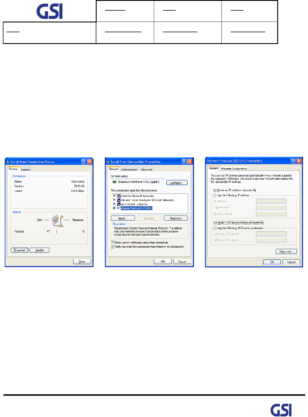
8.1. Configuration the Laptop to Connect to the Repeater
• Connect an Ethernet crossover cable from the LAN port of the repeater’s bottom side to your laptop
1. Go to Local Connection
2. Click on "Properties"
3. Highlight "Internet Protocol"
4. Click on "Properties"
5. Choose "Obtain DNS Server
address automatically"
6. Clink OK
Version
1.3
Date
November 18, 2016
Page
33/ 61
Title
USER MANUAL
Prepared by
Reviewed by
Approved by
33
©2016 GS Instech Co., Ltd. All rights reserved.
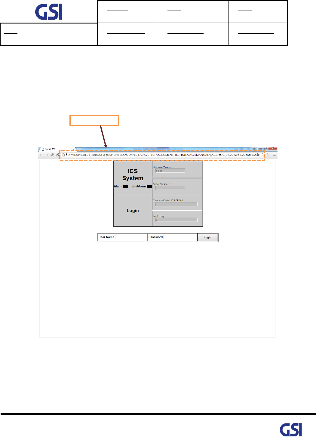
8.2. Login-In Screen
• Web-UI Screen for Log-In
• After Logging, User can be able to operate Web-UI
• Register & Delete a User name/ Password: Refer to 9.8 User Management
• Display Total Alarm & Shutdown Status
• Enter the IP Address "192.168.1.1" into your browser address bar and you will be redirected to the
Login page
Version
1.3
Date
November 18, 2016
Page
34/ 61
Title
USER MANUAL
Prepared by
Reviewed by
Approved by
34
©2016 GS Instech Co., Ltd. All rights reserved.
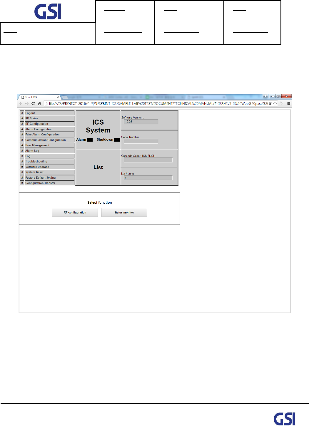
8.3. Main Screen
• Web-UI Screen for Main Menu
• Able to select function RF Configuration & Status monitoring
Version
1.3
Date
November 18, 2016
Page
35/ 61
Title
USER MANUAL
Prepared by
Reviewed by
Approved by
35
©2016 GS Instech Co., Ltd. All rights reserved.
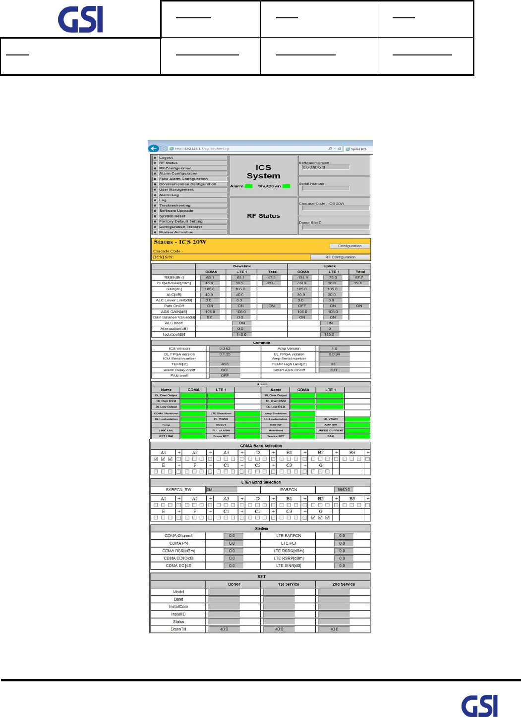
8.4. RF Status
• Web-UI Screen for display Repeater’s RF Status

Version
1.3
Date
November 18, 2016
Page
36/ 61
Title
USER MANUAL
Prepared by
Reviewed by
Approved by
36
©2016 GS Instech Co., Ltd. All rights reserved.
8.5. RF Configuration
• Web-UI Screen in order to change the RF values
• User may change the various RF values of the repeater on this page
• Changes will not take effect until you click "Apply" button
• This menu is where the installer will choose references for specific implementation
Version
1.3
Date
November 18, 2016
Page
37/ 61
Title
USER MANUAL
Prepared by
Reviewed by
Approved by
37
©2016 GS Instech Co., Ltd. All rights reserved.
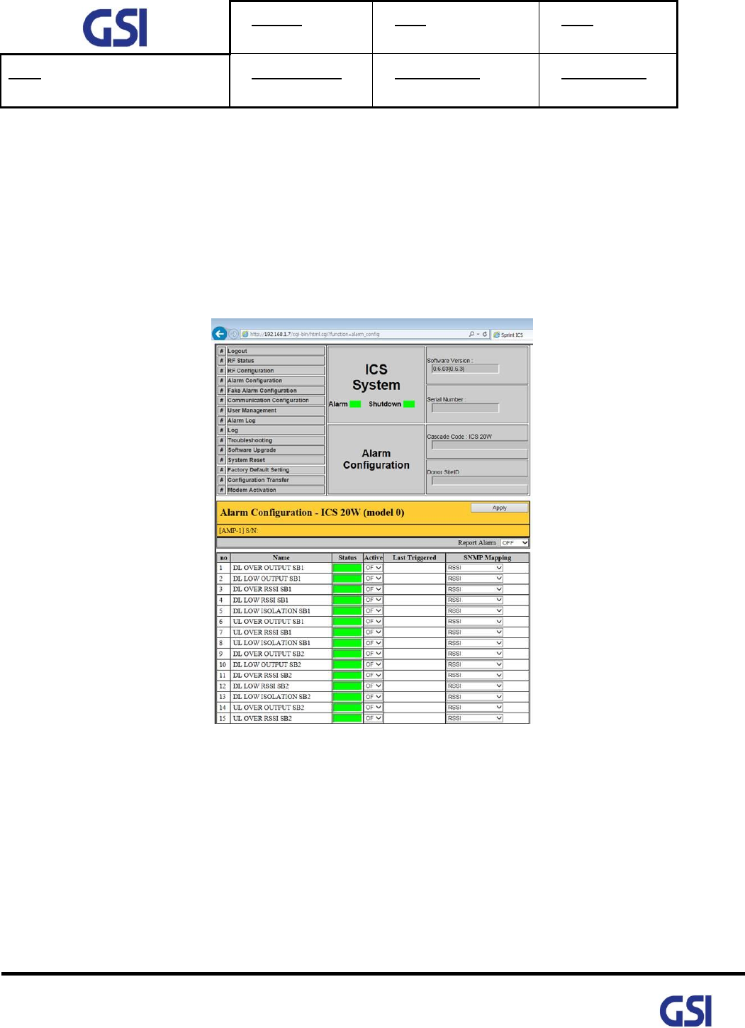
8.6. Alarm Configuration
• Web-UI Screen for Alarm Configurations
• Define a TRAP alarm thru SNMP Mapping
• Decide to activate an each alarm
• When "Report Alarm" is OFF, all alarms are disabled. When "Report Alarm" is ON, alarms can be
Enable/ disabled individually
Version
1.3
Date
November 18, 2016
Page
38/ 61
Title
USER MANUAL
Prepared by
Reviewed by
Approved by
38
©2016 GS Instech Co., Ltd. All rights reserved.
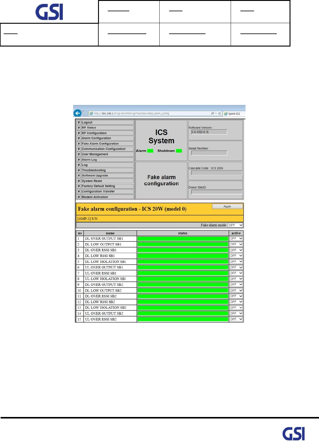
8.7. Fake Alarm Configuration
• Web-UI Screen for Fake Alarm Configurations
• In order to test about transmitting alarm to Sprint Server, Fake alarm occur in SNMP Board

Version
1.3
Date
November 18, 2016
Page
39/ 61
Title
USER MANUAL
Prepared by
Reviewed by
Approved by
39
©2016 GS Instech Co., Ltd. All rights reserved.
8.8. Communication Configuration
• Web-UI Screen for Communication Configurations
• Set the information in order to connect to Sprint Server
• On this page you can change the various values related to IP network. Because the Web-UI is based
on the IP network, incorrect configuration may make it impossible to connect to the Web-UI.
• In that case, Contact GSI Technical Support for further instructions

Version
1.3
Date
November 18, 2016
Page
40/ 61
Title
USER MANUAL
Prepared by
Reviewed by
Approved by
40
©2016 GS Instech Co., Ltd. All rights reserved.
8.9. User Management
• Web-UI Screen for Management about user information
• On this page you can create and delete users, change passwords, and assign authorities to individual
users
• Read Authority will only allow the user to view information on the menu pages, but cannot make
any changes
• Read/ Write Authority means the user can view and change various values
• Super User is very similar to and Administrator account

Version
1.3
Date
November 18, 2016
Page
41/ 61
Title
USER MANUAL
Prepared by
Reviewed by
Approved by
41
©2016 GS Instech Co., Ltd. All rights reserved.
8.10. Alarm Log
• Web-UI Screen for finding Alarm log
• You can see the history of reported and reset Alarms. When an alarm is reported,
the name and time of the alarm is displayed along with its current status
• Red means the alarm is reported, Green means the alarm has returned to normal status
• An alarm will only be reported if the alarm condition lasts longer that the set value in the
"Delay Alarm Reporting Minutes" field, found on the RF configuration page
Version
1.3
Date
November 18, 2016
Page
42/ 61
Title
USER MANUAL
Prepared by
Reviewed by
Approved by
42
©2016 GS Instech Co., Ltd. All rights reserved.
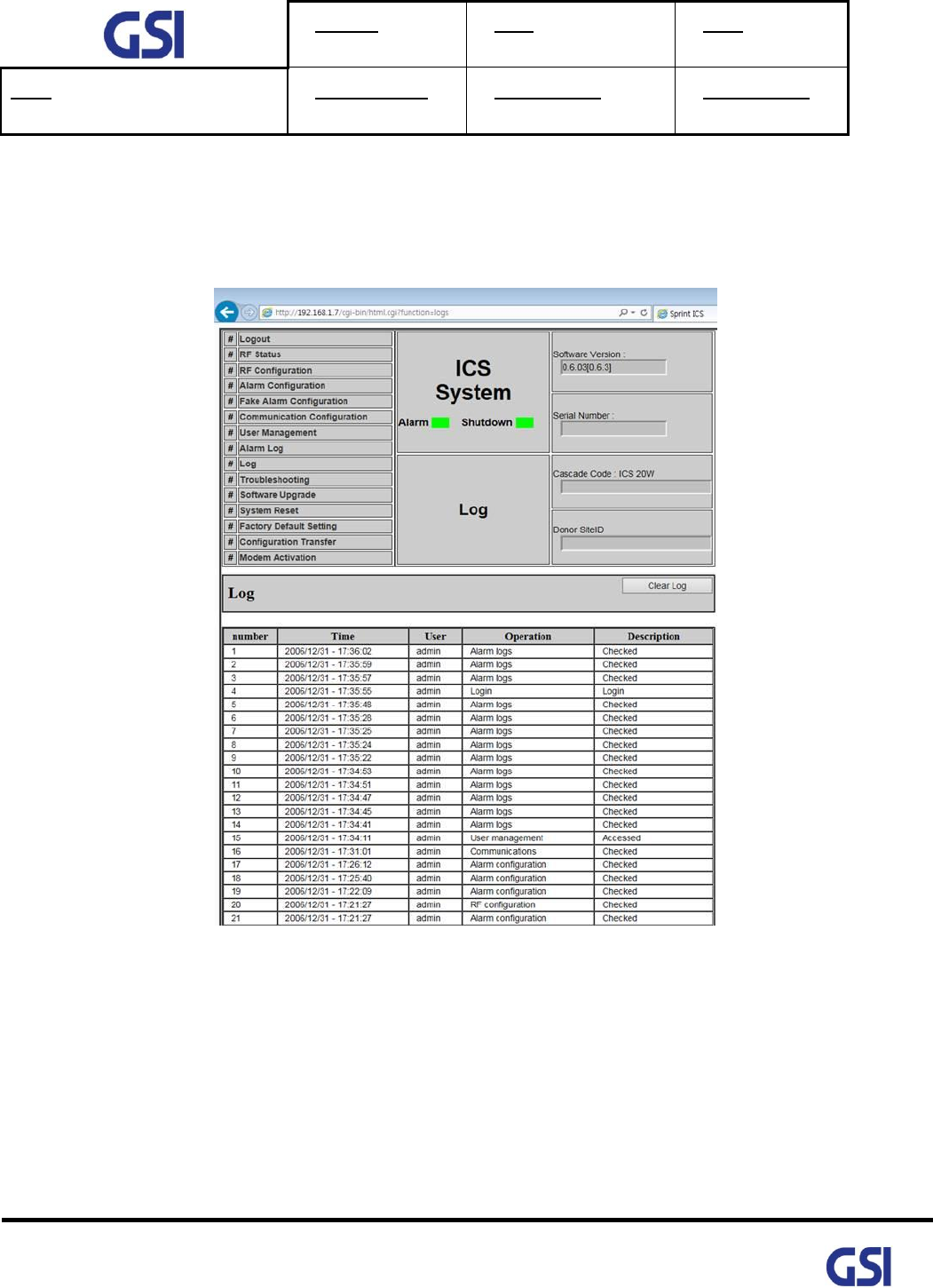
8.11. Log
• Web-UI Screen for reading a List of operation history
• Logs will maintain a history of up to 30 cycles

Version
1.3
Date
November 18, 2016
Page
43/ 61
Title
USER MANUAL
Prepared by
Reviewed by
Approved by
43
©2016 GS Instech Co., Ltd. All rights reserved.
8.12. Troubleshooting
• Web-UI Screen for informing a contact information in case of occurring Field Troubleshooting

Version
1.3
Date
November 18, 2016
Page
44/ 61
Title
USER MANUAL
Prepared by
Reviewed by
Approved by
44
©2016 GS Instech Co., Ltd. All rights reserved.
8.13. Software Update
• Web-UI Screen for downloading a software
• Procedure
1. Go to "Remote Software Upgrade" link
2. Click Browse button to select the upgrade file from the laptop
3. Choose the file to upgrade. Provided by manufacturer. After you choose the file,
You should click "upload" to send the file from your laptop to the Repeater
4. Once the file name and file size are displayed, click "Upgrade" to start the upgrade installation
5. Provided file will have the following format: smc_vxxxx_xxxxxxxx.tar.gz
Version
1.3
Date
November 18, 2016
Page
45/ 61
Title
USER MANUAL
Prepared by
Reviewed by
Approved by
45
©2016 GS Instech Co., Ltd. All rights reserved.
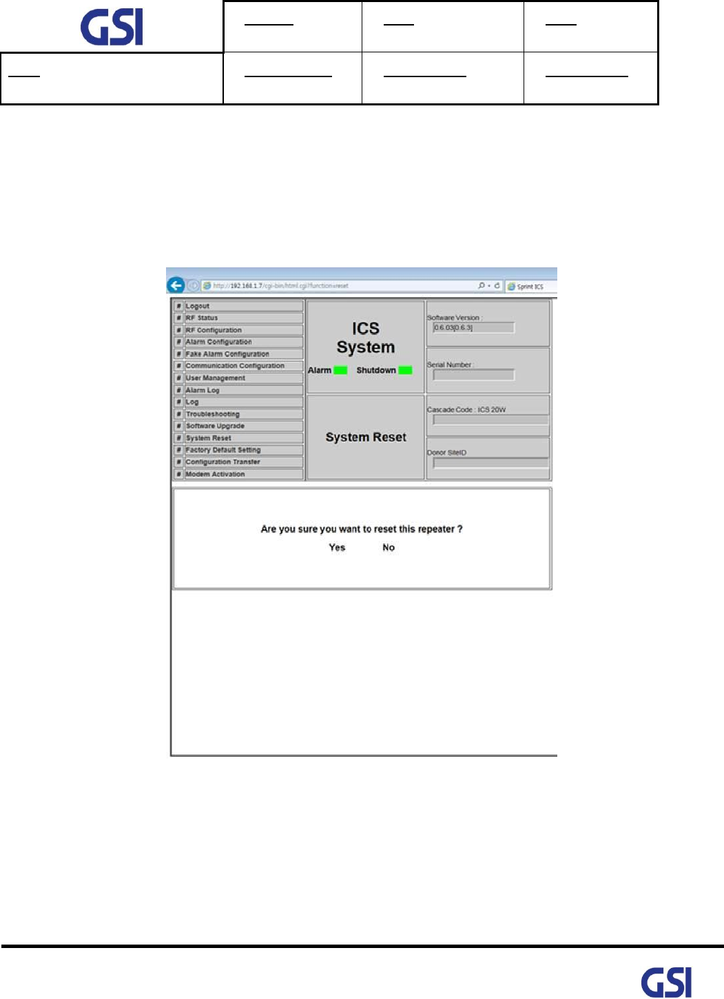
8.14. System Reset
• Web-UI Screen for resetting the system
• Click on the desired reset action
• Clink "Yes" to reset the repeater via a soft-boot. This will not change any of the current settings
Version
1.3
Date
November 18, 2016
Page
46/ 61
Title
USER MANUAL
Prepared by
Reviewed by
Approved by
46
©2016 GS Instech Co., Ltd. All rights reserved.
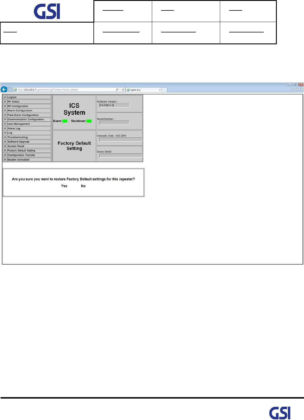
8.15. Factory Default Setting
• Web-UI Screen for Default Setting before operating
Version
1.3
Date
November 18, 2016
Page
47/ 61
Title
USER MANUAL
Prepared by
Reviewed by
Approved by
47
©2016 GS Instech Co., Ltd. All rights reserved.
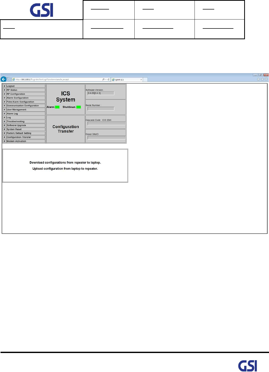
8.16. Configuration Transfer
• Web-UI Screen for mutual information transfer between Repeater and Local Craft
Version
1.3
Date
November 18, 2016
Page
48/ 61
Title
USER MANUAL
Prepared by
Reviewed by
Approved by
48
©2016 GS Instech Co., Ltd. All rights reserved.
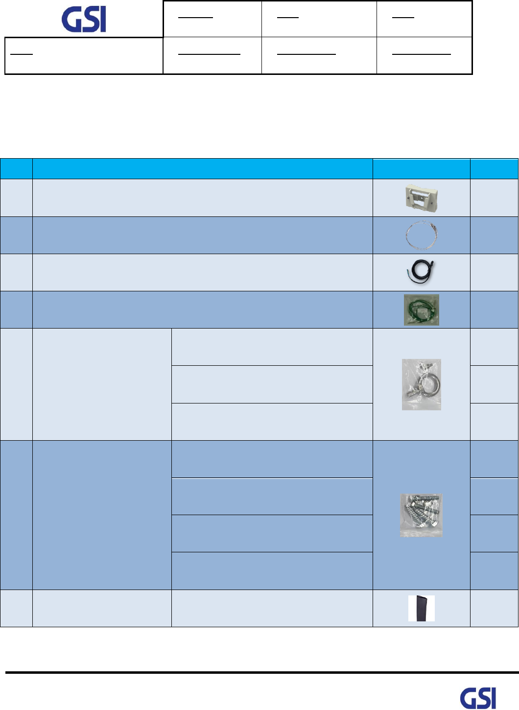
9. System Installation
• This chapter describes how to install the repeater and Cabling method
• The needed accessories and tools are list up as below
#
Contents
Picture
Q’ty
1
Mounting Bracket
1EA
2
Steel band
1EA
3
AC Power Cable SJT 3/16 AWG, 6ft
1EA
4
Frame Ground Cable with Tubular Cable Lug, 6ft
1EA
5
Installation purchase set
EYE BOLT(M12)
1EA
M5x12mm WRENCH BOLT, SEMS
2EA
PH(+) M4x8mm ,SEMS
4EA
6
Mounting Screw set
LAG SCREW 3/8”x3”
2EA
HEX HEAD 3/8”x2”, SCM440
2EA
Φ10.5mm/Φ21mm PLAIN WASHER
2EA
Φ10.2mm/Φ18.4mm SPRING WASHER
2EA
7
Tubing Tube Sleeve Black
Φ30mm/L:150mm Adhesive Polyolefin
3:1 Heat Shrink
1EA
Table 11. GST-Ic-ELITE-1943 Installation Accessories

Version
1.3
Date
November 18, 2016
Page
49/ 61
Title
USER MANUAL
Prepared by
Reviewed by
Approved by
49
©2016 GS Instech Co., Ltd. All rights reserved.
9.1. Warnings and Hazards
9.1.1. Electric Shock
• Opening the Repeater could result in electrical shock and may cause severe
injury
• Operating the Repeater with antennas in very close proximity facing each other
could lead to severe damage to the repeater
9.1.2. Exposure to RF
Working with the repeater while in operation, may expose the technician to
RF electromagnetic fields that exceed FCC Rules for human expose.
Visit the FCC Website at http://www.fcc.gov/oet/rfsafety to learn more about
The effects of exposure to RF electromagnetic fields
9.2. Position Antenna
• After installing antennas, Installer should ensure line of Site
• Actual separation distance is determined upon gain of antenna used
So, maintain a minimum safe distance that achieved isolation 60dB
at least while operating near the donor and service antenna
• Antennas needs to be mounted outdoors on a permanent structure
• Antenna’s general specification is below
PART
Donor
Service
Frequency
1850-1995
1850-1995
Gain
20dBi
20dBi
VSWR
< 1.5
< 1.5
Polarization
Vertical
Vertical
FRB
> 40
> 25
Size (Inch)
27.6 x 27.6 x 5.4
78.7 x 11.8 x 6.2
Donor
Antenna
Service
Antenna
Version
1.3
Date
November 18, 2016
Page
50/ 61
Title
USER MANUAL
Prepared by
Reviewed by
Approved by
50
©2016 GS Instech Co., Ltd. All rights reserved.
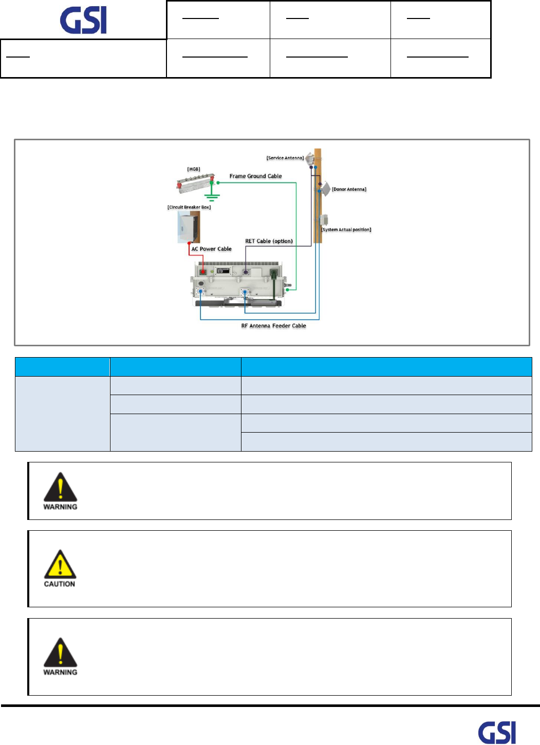
9.3. Cabling
The cabling diagram of the GST-IC-ELITE1943 is as follows
From
To
Cable
GST-IC-ELITE1943
MGB
Frame Ground Cable: AWG 6/ 10ft
Circuit Breaker Box
AC Power Cable: AWG 16/ 6ft
RF Antennas
RF Antenna Feeder Cable: 1/2 inch Feeder Line
RET control Cable (option)
No use for the unauthorized device
When installing the system, must check the devices that use is authorized.
This conditions apply antenna, cable and coupling device if necessary.
Circuit Breaker Installation in the Box for Overcurrent Protection
Must install the circuit breaker between the system and main AC source for separating.
Make sure to install the Circuit breaker on the place to operate easily
Circuit Breaker is able to operate up to 20A
Terminal, Conduit and Cable Size
To install the conduit is according to NAE regulation, and Terminal sixe is according to
NEC regulation
Version
1.3
Date
November 18, 2016
Page
51/ 61
Title
USER MANUAL
Prepared by
Reviewed by
Approved by
51
©2016 GS Instech Co., Ltd. All rights reserved.
9.4. Service Man Installation Guide
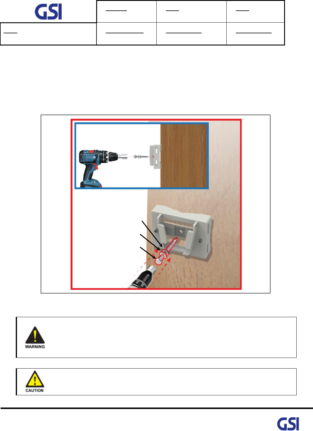
9.4.1. Pole Mount Installation
The procedure for fixing the pole type system is as follows
1) To mount the system on the pole, first fix the bracket on the wanted position.
Figure 14. The way to fix the bracket on the pole (Normal type)
Protection gloves and goggles
Make sure that worker wears protection gloves and goggles to prevent damages from
debris while drilling holes in a Pole or Wall
Cautions while drilling on the pole
Drilling thru-hole on a center of the pole
Repeater
LAG SCREW 3/8"x3"
Φ10.5mm/Φ21mm PLAIN WASHER
Φ10.2mm/Φ18.4mm SPRING WASHER

Version
1.3
Date
November 18, 2016
Page
52/ 61
Title
USER MANUAL
Prepared by
Reviewed by
Approved by
52
©2016 GS Instech Co., Ltd. All rights reserved.
2) To fix the bracket on the pole, strip the bracket using a steel band
Figure 15. Installing the Steel Band
Figure 16. The way to using a Steel Band
Cautions System leveling
Before fixing the bracket, Check the horizontal and vertical level using a spirit level
Fasten the Steel-Band tightly
Buckle the Steel-Band
Version
1.3
Date
November 18, 2016
Page
53/ 61
Title
USER MANUAL
Prepared by
Reviewed by
Approved by
53
©2016 GS Instech Co., Ltd. All rights reserved.
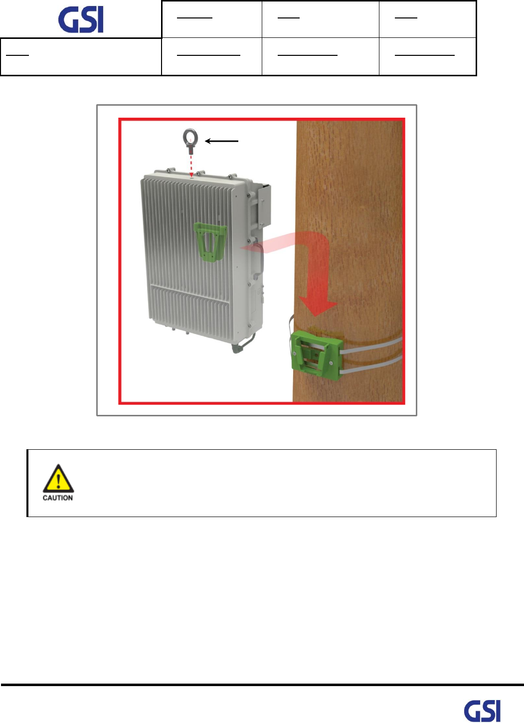
3) Hang the system to the hooking position at the top of the mounting bracket
Figure 17. The way to hang the system for Pole Mounting
Cautions while lifting the system
Regarding equipment weight and size, decide to the way to lift the system
Eye Bolt (M12)
Version
1.3
Date
November 18, 2016
Page
54/ 61
Title
USER MANUAL
Prepared by
Reviewed by
Approved by
54
©2016 GS Instech Co., Ltd. All rights reserved.
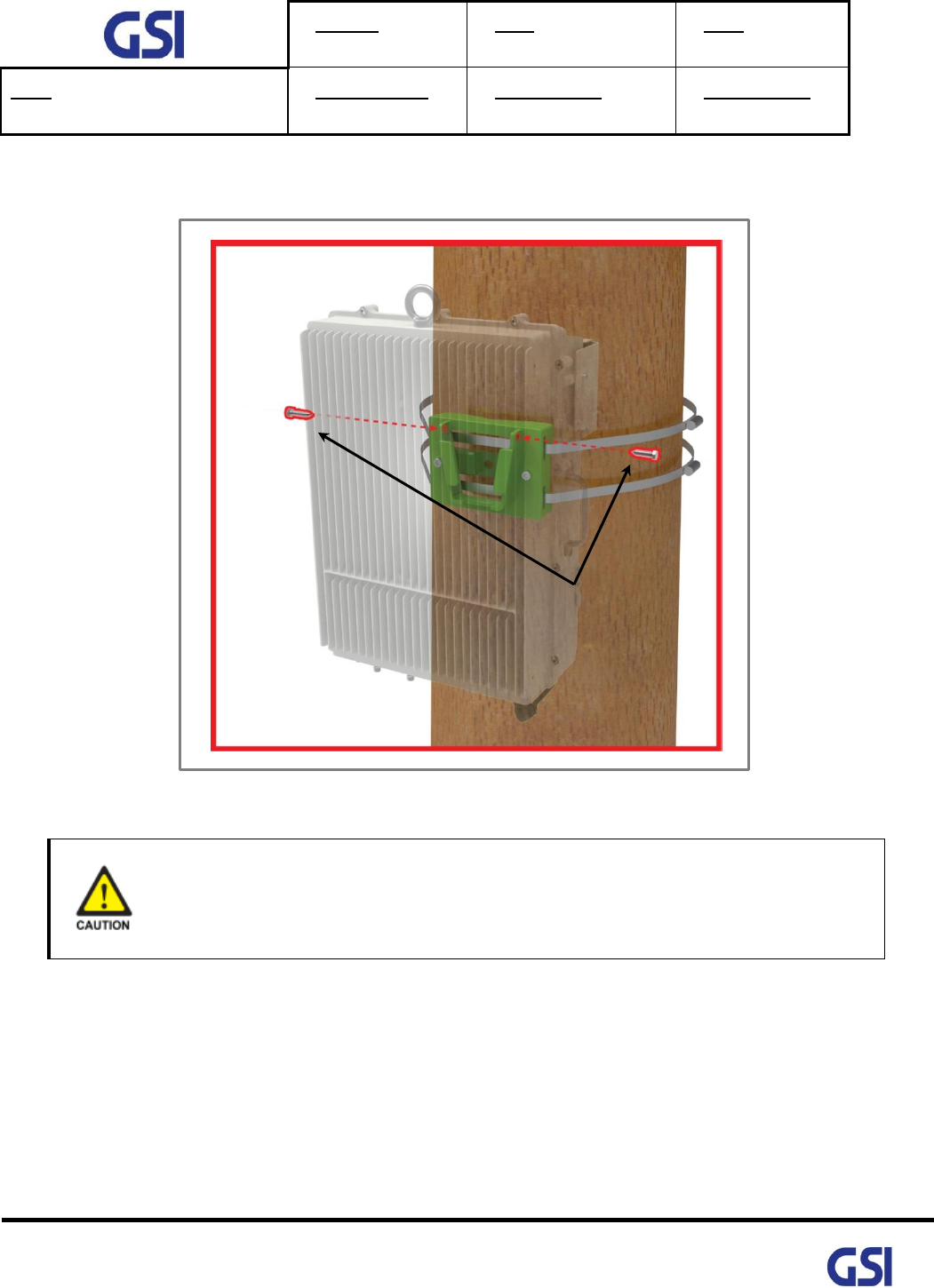
4) Align the system with the fixing holes of the mounting bracket and fix them firmly
Figure 18. The way to fix firmly the System for Pole Mounting
Cautions System leveling
Before fixing the system, Check the horizontal and vertical level using a spirit level
M5x12mm WRENCH BOLT, SEMS
Version
1.3
Date
November 18, 2016
Page
55/ 61
Title
USER MANUAL
Prepared by
Reviewed by
Approved by
55
©2016 GS Instech Co., Ltd. All rights reserved.
9.4.2. Wall Mount Installation
The procedure for fixing the wall type system is as follows:
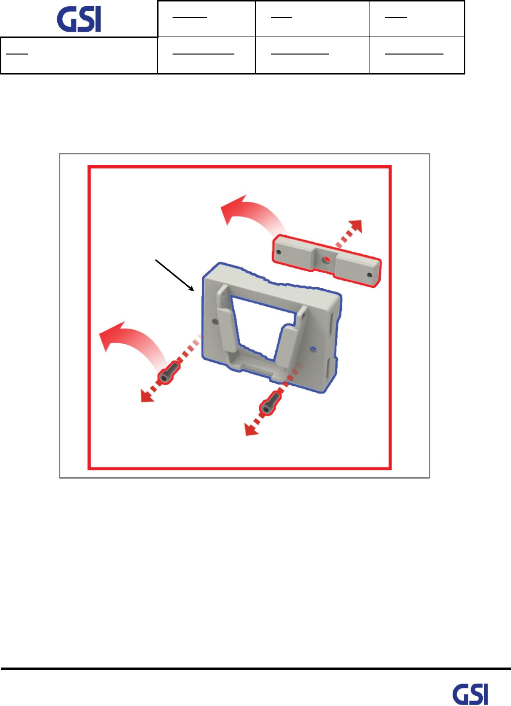
1) Before fixing the bracket on the wall, detach a piece of bracket
Figure 19. Detach the unused bracket and Bolt
USE ONLY!!!
Version
1.3
Date
November 18, 2016
Page
56/ 61
Title
USER MANUAL
Prepared by
Reviewed by
Approved by
56
©2016 GS Instech Co., Ltd. All rights reserved.
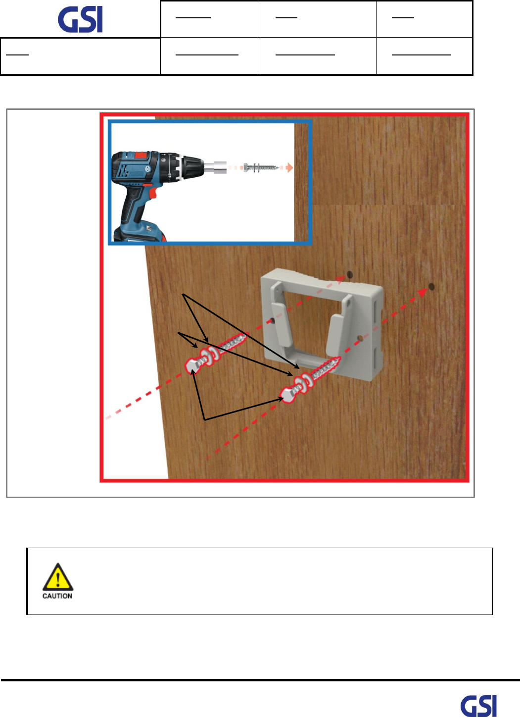
2) To mount the system on the wall, first fix the bracket on the wanted position
Figure 20. Fixing the Bracket for installing a Wall Mount
Wall Thickness
Wall thickness to fix the system is 1.5 inch over at least.
Φ10.5mm/Φ21mm PLAIN WASHER
Φ10.2mm/Φ18.4mm SPRING WASHER
LAG SCREW 3/8"x3"
Φ10.5mm/Φ21mm PLAIN WASHER
Φ10.2mm/Φ18.4mm SPRING WASHER

Version
1.3
Date
November 18, 2016
Page
57/ 61
Title
USER MANUAL
Prepared by
Reviewed by
Approved by
57
©2016 GS Instech Co., Ltd. All rights reserved.
3) Hang the system to the hooking position at the top of the mounting bracket
Figure 21. The way to hang the system for Wall Mounting
4) Align the system with the fixing holes of the mounting bracket and fix them firmly
Figure 22. The way to fix firmly the System for Wall Mounting
M5x12mm WRENCH BOLT, SEMS
Version
1.3
Date
November 18, 2016
Page
58/ 61
Title
USER MANUAL
Prepared by
Reviewed by
Approved by
58
©2016 GS Instech Co., Ltd. All rights reserved.
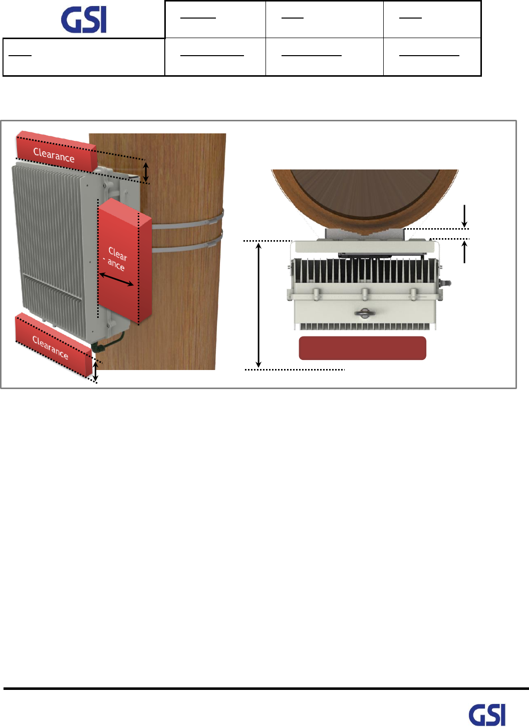
9.4.3. Recommended Distance for installing system mounting
Figure 23. Recommended Distance for installing system mounting
1" (25.4mm)
47.8" (1.21M) include repeater size
Clearance area
30" (0.762M)
30" (0.762M)
20" (0.508M)
Same as both sides

Version
1.3
Date
November 18, 2016
Page
59/ 61
Title
USER MANUAL
Prepared by
Reviewed by
Approved by
59
©2016 GS Instech Co., Ltd. All rights reserved.
9.5. Cable Connection
9.5.1. AC Power cable connection
• Repeater supports a free AC Input voltage from 110V to 240V
• Provided Power cable is single type, so it can be used flexibly
• The pin description of AC Port is below. User should connect exact polarity of AC
Port Outlook
(System Side)
Port numbering
for MS
NAME
Description
MS-3102A-10SL-3P
A
AC_H
AC Hot
B
AC_N
AC Neutral
C
F.G
Frame Ground
• The specification & Connection of AC Power Cable
- A: MS3106A-10SL-3S
- Connect Port A for inserting AC Power
-
A
A

Version
1.3
Date
November 18, 2016
Page
60/ 61
Title
USER MANUAL
Prepared by
Reviewed by
Approved by
60
©2016 GS Instech Co., Ltd. All rights reserved.
9.5.2. FAN Power Cable Connection
Port Outlook
(System Side)
Port numbering
for MS
NAME
Description
MS3102A14S-2P
A
Red
+24 VDC
B
Black
Frame Ground
C
Yellow
FAN Alarm #1
D
Brown
Reserved
9.5.3. RET Cable Connection
Port Outlook
(System Side)
Port numbering
for MS
NAME
Description
SU20SPR-8S
3
RS485B
Communication
4
DGND
Frame Ground
5
RS485A
Communication
6
+29 V
1.5A max
7
DC Return
Retune DC Power
1, 2, 8
NC
-
9.5.4. Local Maintenance Connection
• Repeater Support a RJ-45 connector
Version
1.3
Date
November 18, 2016
Page
61/ 61
Title
USER MANUAL
Prepared by
Reviewed by
Approved by
61
©2016 GS Instech Co., Ltd. All rights reserved.
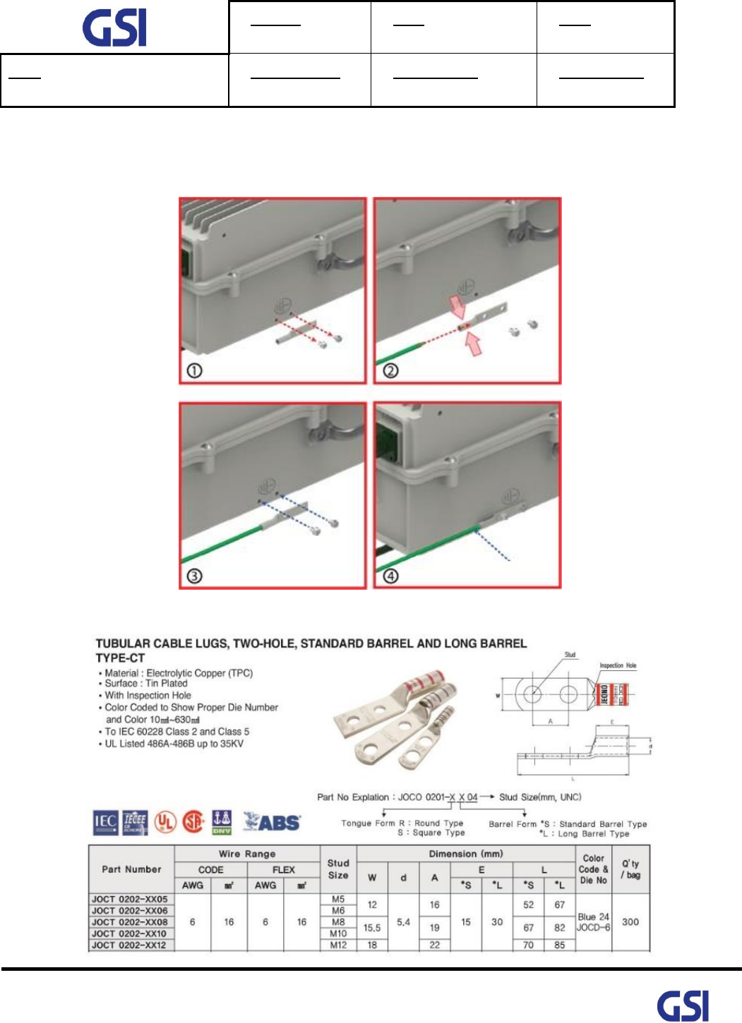
9.5.5. Grounding cable Connection
• Frame(Earth) Wire size is AWG #6. The way to install the grounding cable is below
• The specification of ground terminal lug is like below (Refer to JOCT 0202-RL05)
Frame Ground