GS Instech MCPA-2002S-SP Multi-Carrier Power Amplifier User Manual 1
GS Instruments Co., Ltd. Multi-Carrier Power Amplifier 1
UserManual.wiki
>
GS Instech
>
MCPA 2002S SP User Manual
User Manual
Navigation menu
Upload a User Manual
Namespaces
Wiki Guide
HTML
PDF
Info
Views
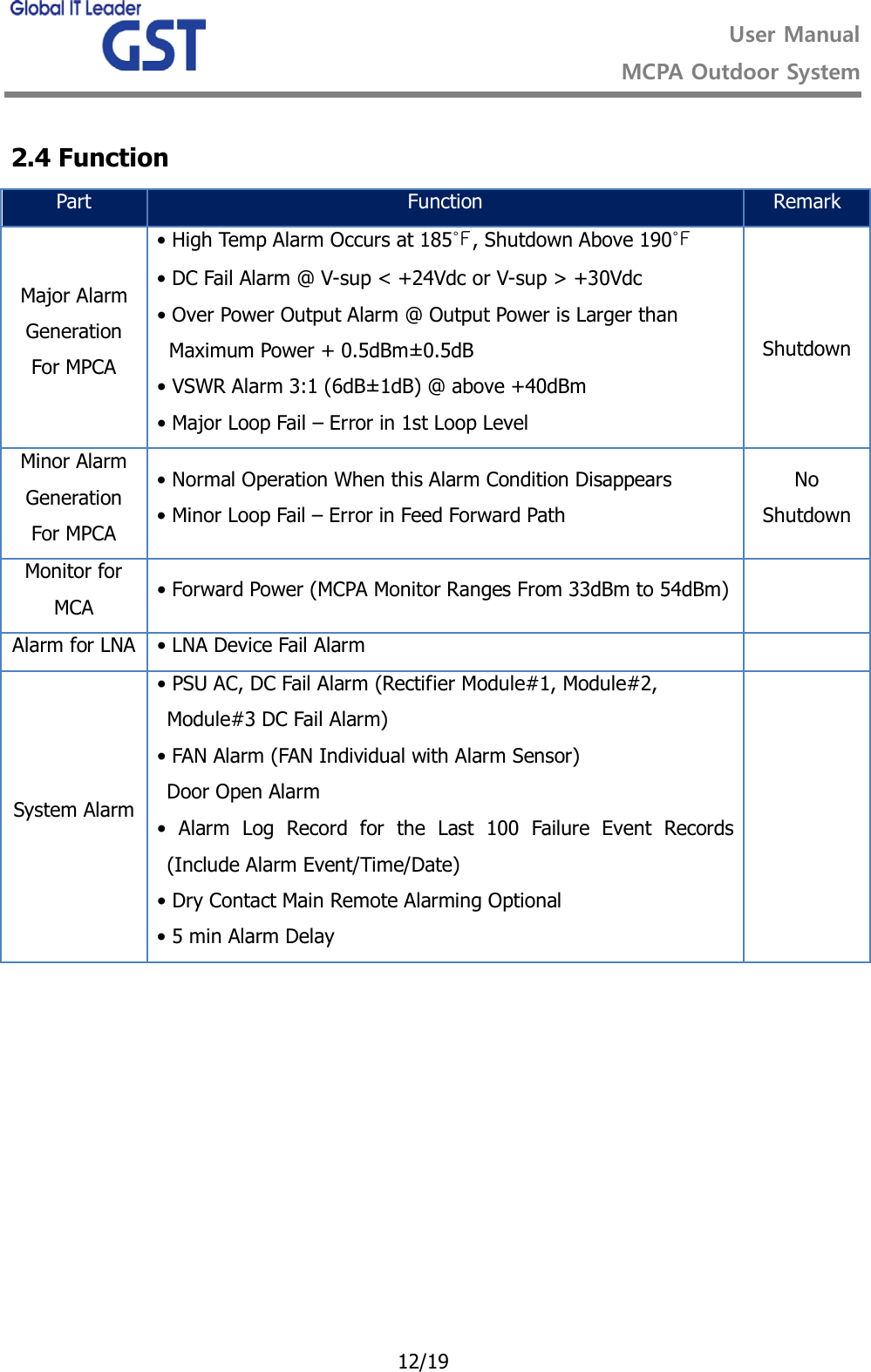
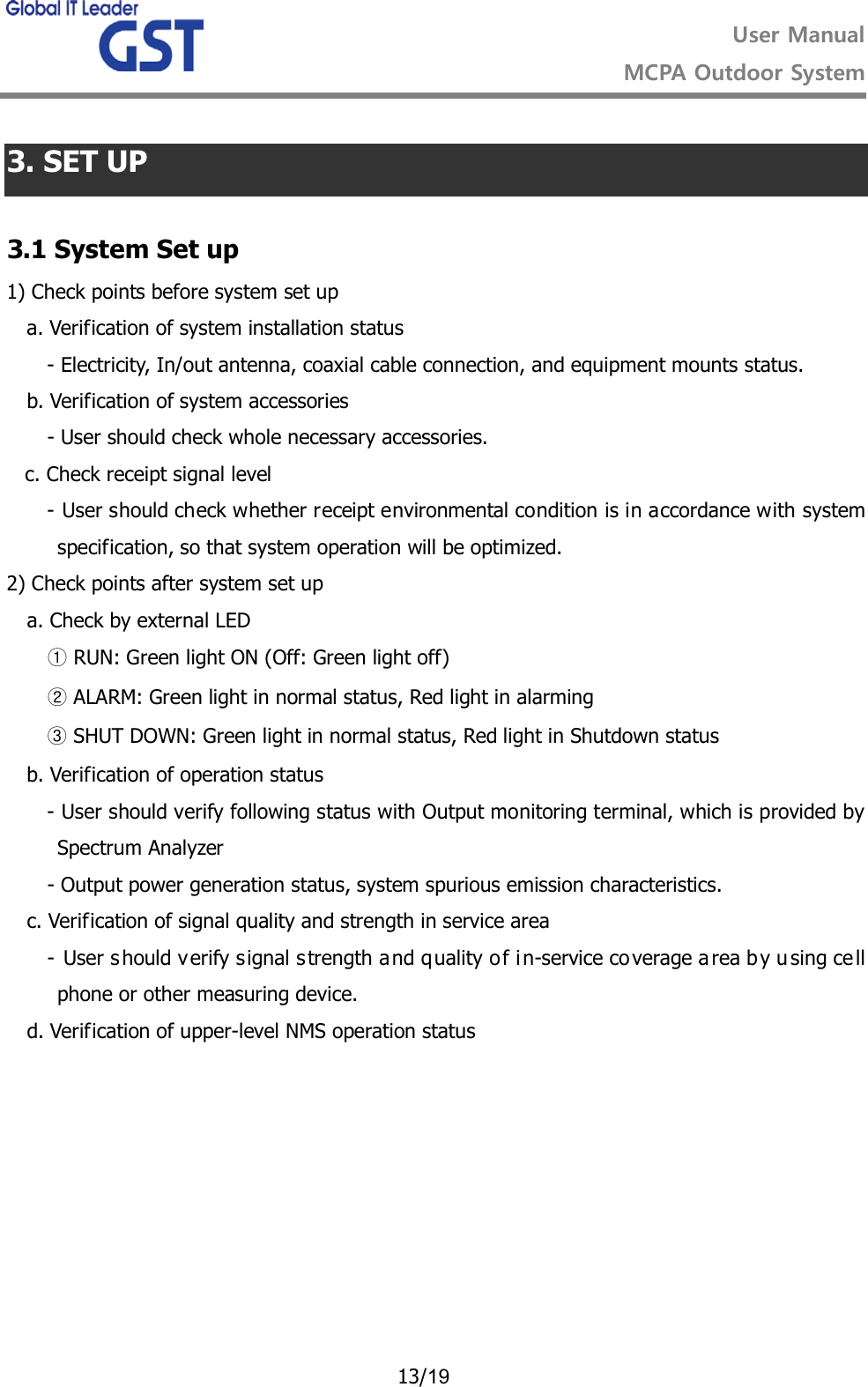
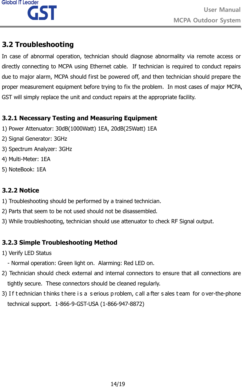
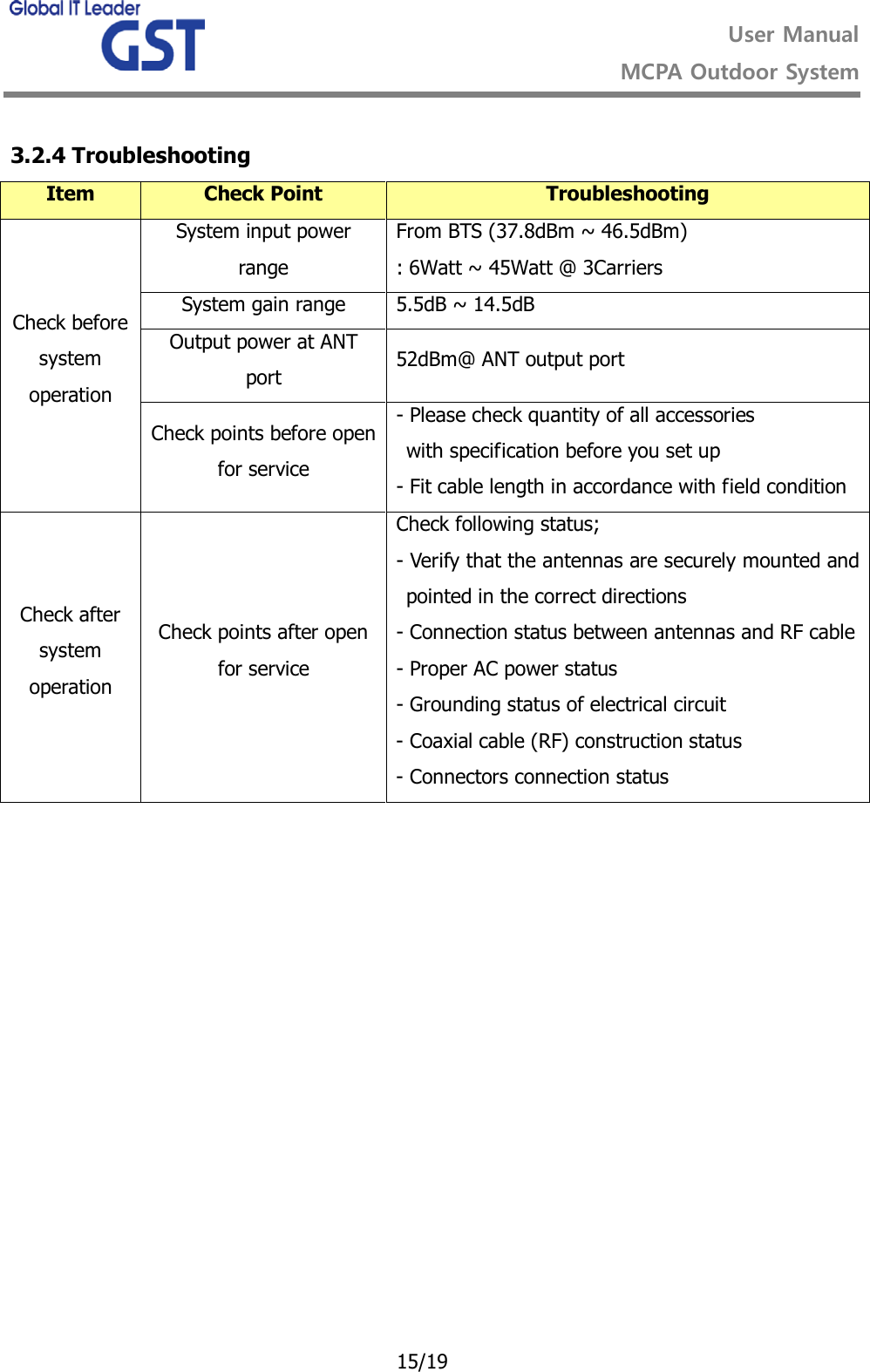
User Manual
Discussion / Help
Navigation
![User Manual MCPA Outdoor System 6/19 2.2 System Design and Operation 2.2.1 System Design [Figure1 Outdoor System]](https://usermanual.wiki/GS-Instech/MCPA-2002S-SP/User-Guide-1776064-Page-6.png)
![User Manual MCPA Outdoor System 7/19 [Figure2 Cabinet Front, Rear] [Figure3 System Dimensions]](https://usermanual.wiki/GS-Instech/MCPA-2002S-SP/User-Guide-1776064-Page-7.png)
![User Manual MCPA Outdoor System 8/19 [Figure4 PSU]](https://usermanual.wiki/GS-Instech/MCPA-2002S-SP/User-Guide-1776064-Page-8.png)
![User Manual MCPA Outdoor System 9/19 [Figure5 MCA] [Figure6 MCU]](https://usermanual.wiki/GS-Instech/MCPA-2002S-SP/User-Guide-1776064-Page-9.png)
![User Manual MCPA Outdoor System 10/19 [Figure7 FEU] [Figure8 RF Switch] [Figure9 Bias-T]](https://usermanual.wiki/GS-Instech/MCPA-2002S-SP/User-Guide-1776064-Page-10.png)
![User Manual MCPA Outdoor System 11/19 2.3 Cabinet Flow of Air [Figure12 Flow of Air]](https://usermanual.wiki/GS-Instech/MCPA-2002S-SP/User-Guide-1776064-Page-11.png)