GS Instech MCPA-2002S-SP Multi-Carrier Power Amplifier User Manual 1
GS Instruments Co., Ltd. Multi-Carrier Power Amplifier 1
User Manual

User Manual
MCPA Outdoor System
1/24
MCPA Outdoor System
User Manual
May, 2012
Version 1.0


User Manual
MCPA Outdoor System
3/19
U.S.A.
U.S.FEDERAL COMMUNICATIONS COMMISSION RADIO FREQUENCY INTERFERENCE
STATEMENT INFORMATION TO THE USER
Caution: Any changes or mo difications to this device not explicitly a pproved b y m anufacturer
could void your authority to operate this equipment.
NOTE: This equipment has been tested and founded to comply with the limits for a Class A
digital device pursuant to Part 15 of the FCC Rules. These limits are designed to provide
reasonable protection against harmful interference in a residential installation.
This equipment g enerates, uses, a nd can r adiate radio f requency energy and, if n ot installed
and u sed i n a ccordance w ith the i nstructions, ma y c ause h armful i nterference t o r adio
communications. Operation of this equipment in a residential area is likely to cause harmful
interference i n w hich ca se t he u ser w ill b e r equired t o c orrect t he i nterference a t h is o wn
expense.

User Manual
MCPA Outdoor System
4/19
1. SUMMARY
1.1 Overview
MCPA System was designed to improve communication coverage/service quality and customer
satisfaction for mobile handset users in coverage areas such as metropolis, urban areas, high
dense area and BTS Cell are target candidates for installation. MCPA (Multi-Carrier Power
Amplifier) B ooster system provides high performance network u pgrade s olution r anging from
highly capital-intensive options
1.2 Characteristic
Compensate Loss of Feeder Line between BTS and Antenna.
Expand US-PCS BTS Coverage/ Service Coverage.
Continuous Service with no Trouble is available by Bypass. (RF Switch)
Be able to amplify output power of up to 200W due to enable to regulate Gain of 5.5
~14.5dB on the case of TX Signal though low Output power of existing BTS.
Enable to Remote Control through communication of SMS using by existing PCS Network,
monitor and manage easily for a notebook through Ethernet communication.
Abbreviation
MCPA : Multi-Carrier Power Amplifier
BTS: Base Transceiver Station
MCA: Multi-Carrier Amplifier
FEU: Front End Unit
MCU: Micro Controller Unit
PSU: Power Supply unit

User Manual
MCPA Outdoor System
5/19
2. System Configuration
2.1 System Description
2.1.1 Linear Technology
RF Circuit Composition is Simple
Feed Forward of Matched Broad-band Quality
Feed Forward Linear Technology Increases Efficiency and Reduces Heat
2.1.2 Modular System
If One Sector MCA Module Fails, the Other Sectors Will not be affected Modules
Moved In and Out for Easy Replacement, Optimizes Size
2.1.3 Passive Intermodulation
Poor Contact Junctions
Components Made with or Plated with Materials that Exhibit Some Level of Hysteresis
Low Passive IMD System
2.1.4 Safety Design
Individual FAN Temperature Sensor
Automatic Bypass Function
2.1.5 User Friendly
Web UI Interface, Easy Check and Control
System/Status: Displays current firmware and user controllable configurations.
Status/Alarm: Displays the status of all the individual alarm parameters.
System/Configuration: Displays and allows modification to system configurations.
System/Download - Firmware related interface.
Dry Contact Alarm - interface to existing base station alarm reporting circuits.

User Manual
MCPA Outdoor System
6/19
2.2 System Design and Operation
2.2.1 System Design
[Figure1 Outdoor System]
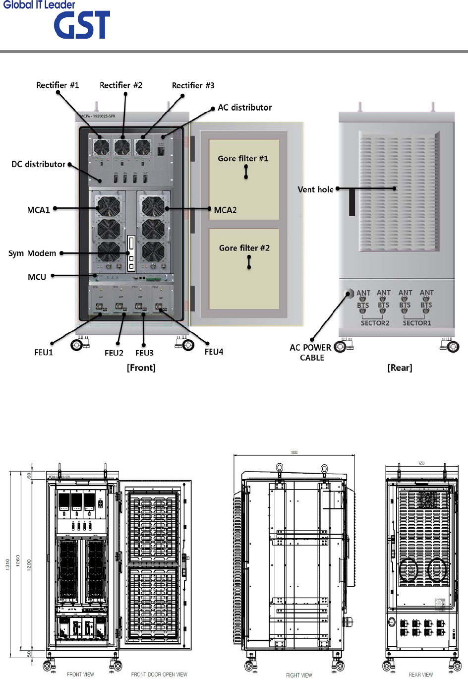
User Manual
MCPA Outdoor System
7/19
[Figure2 Cabinet Front, Rear]
[Figure3 System Dimensions]
User Manual
MCPA Outdoor System
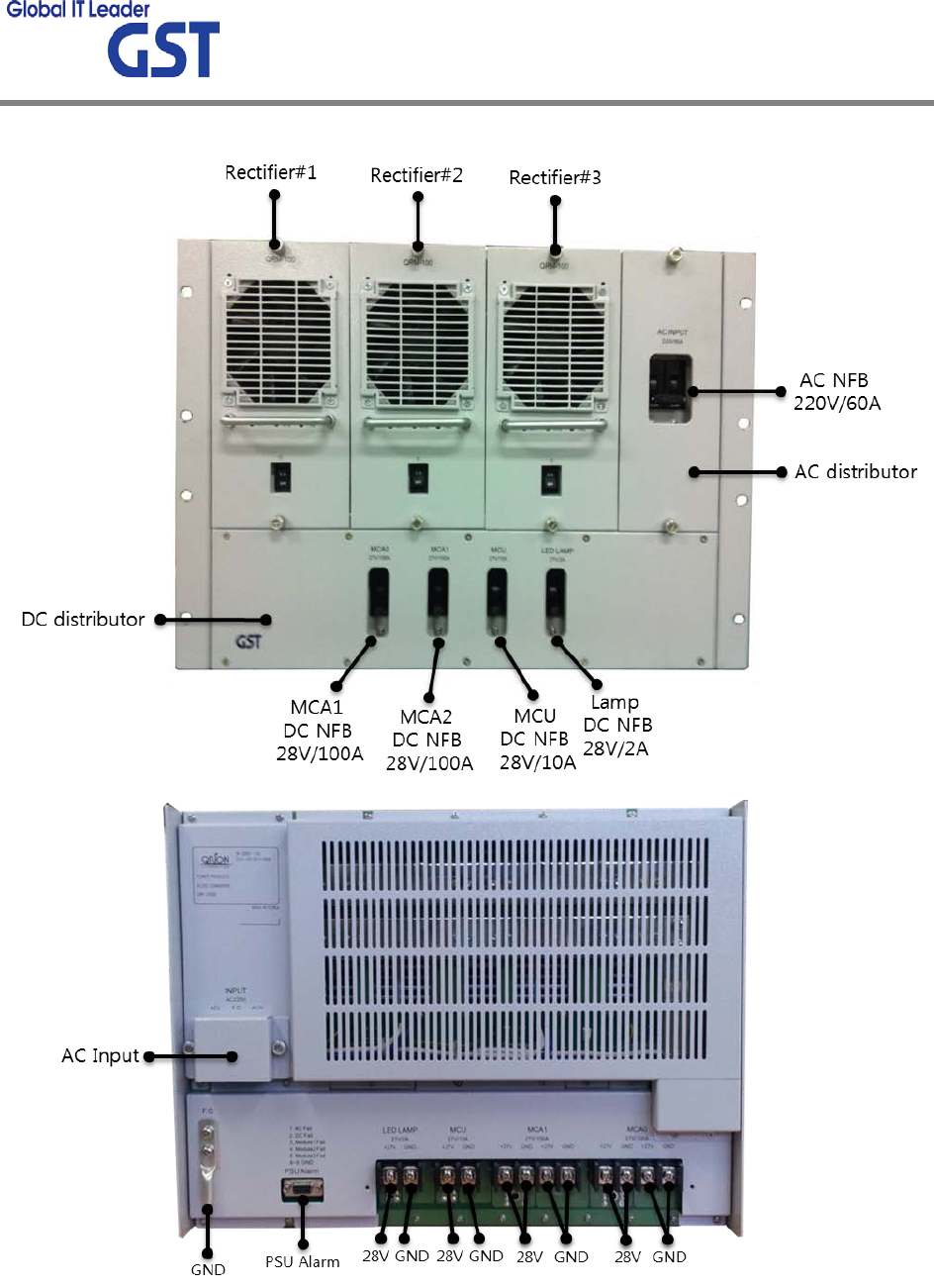
8/19
[Figure4 PSU]
User Manual
MCPA Outdoor System
9/19
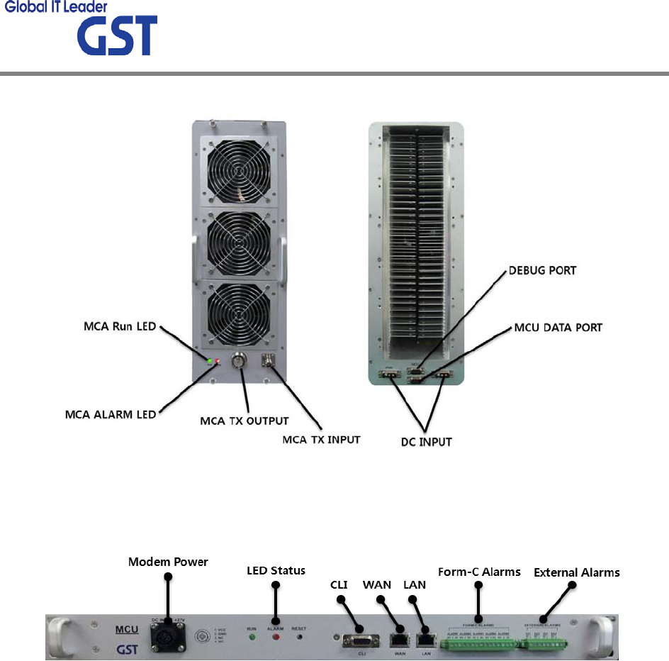
[Figure5 MCA]
[Figure6 MCU]
User Manual
MCPA Outdoor System
10/19
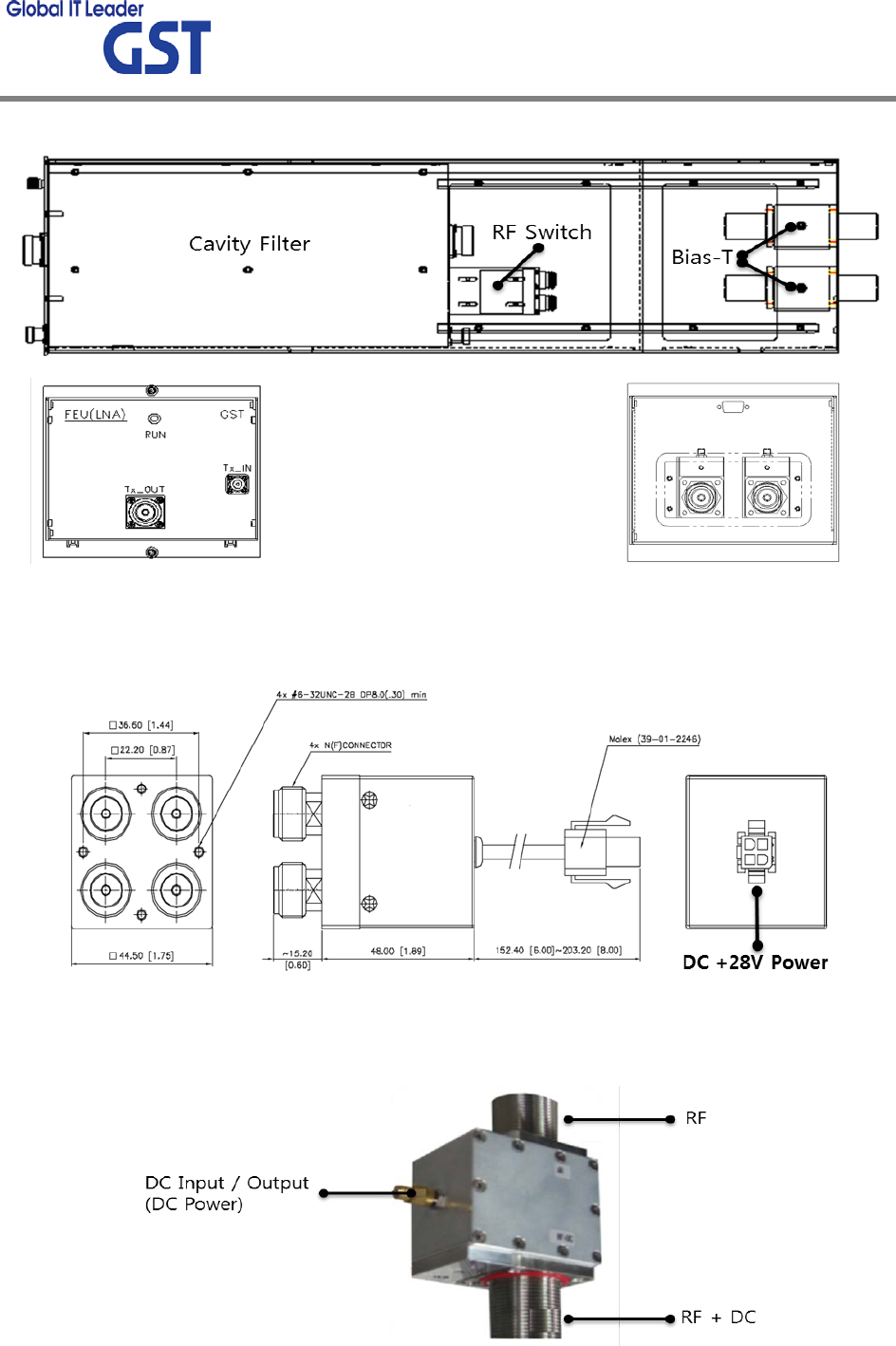
[Figure7 FEU]
[Figure8 RF Switch]
[Figure9 Bias-T]
User Manual
MCPA Outdoor System
11/19
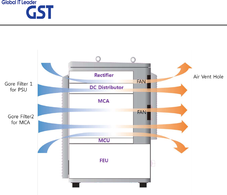
2.3 Cabinet Flow of Air
[Figure12 Flow of Air]

User Manual
MCPA Outdoor System
12/19
.4 Function
Part
Function
Remark
Major Alarm
Generation
For MPCA
• High Temp Alarm Occurs at 185℉, Shutdown Above 190℉
• DC Fail Alarm @ V-sup < +24Vdc or V-sup > +30Vdc
• Over Power Output Alarm @ Output Power is Larger than
Maximum Power + 0.5dBm±0.5dB
• VSWR Alarm 3:1 (6dB±1dB) @ above +40dBm
• Major Loop Fail – Error in 1st Loop Level
Shutdown
Minor Alarm
Generation
For MPCA
• Normal Operation When this Alarm Condition Disappears
• Minor Loop Fail – Error in Feed Forward Path
No
Shutdown
Monitor for
MCA • Forward Power (MCPA Monitor Ranges From 33dBm to 54dBm)
Alarm for LNA
• LNA Device Fail Alarm
System Alarm
• PSU AC, DC Fail Alarm (Rectifier Module#1, Module#2,
Module#3 DC Fail Alarm)
• FAN Alarm (FAN Individual with Alarm Sensor)
Door Open Alarm
• Alarm Log Record for the Last 100 Failure Event Records
(Include Alarm Event/Time/Date)
• Dry Contact Main Remote Alarming Optional
• 5 min Alarm Delay

User Manual
MCPA Outdoor System
13/19
. SET UP
.1 System Set up
1) Check points before system set up
a. Verification of system installation status
- Electricity, In/out antenna, coaxial cable connection, and equipment mounts status.
b. Verification of system accessories
- User should check whole necessary accessories.
c. Check receipt signal level
- User should check whether receipt environmental condition is in accordance with system
specification, so that system operation will be optimized.
2) Check points after system set up
a. Check by external LED
① RUN: Green light ON (Off: Green light off)
② ALARM: Green light in normal status, Red light in alarming
③ SHUT DOWN: Green light in normal status, Red light in Shutdown status
b. Verification of operation status
- User should verify following status with Output monitoring terminal, which is provided by
Spectrum Analyzer
- Output power generation status, system spurious emission characteristics.
c. Verification of signal quality and strength in service area
- User should v erify signal strength and quality of i n-service co verage a rea b y u sing ce ll
phone or other measuring device.
d. Verification of upper-level NMS operation status

User Manual
MCPA Outdoor System
14/19
.2 Troubleshooting
In case of abnormal operation, technician should diagnose abnormality via remote access or
directly connecting to MCPA using Ethernet cable. If technician is required to conduct repairs
due to major alarm, MCPA should first be powered off, and then technician should prepare the
proper measurement equipment before trying to fix the problem. In most cases of major MCPA,
GST will simply replace the unit and conduct repairs at the appropriate facility.
.2.1 Necessary Testing and Measuring Equipment
1) Power Attenuator: 30dB(1000Watt) 1EA, 20dB(25Watt) 1EA
2) Signal Generator: 3GHz
3) Spectrum Analyzer: 3GHz
4) Multi-Meter: 1EA
5) NoteBook: 1EA
.2.2 Notice
1) Troubleshooting should be performed by a trained technician.
2) Parts that seem to be not used should not be disassembled.
3) While troubleshooting, technician should use attenuator to check RF Signal output.
.2.3 Simple Troubleshooting Method
1) Verify LED Status
- Normal operation: Green light on. Alarming: Red LED on.
2) Technician should check external and internal connectors to ensure that all connections are
tightly secure. These connectors should be cleaned regularly.
3) I f t echnician t hinks t here i s a s erious p roblem, c all a fter s ales t eam for o ver-the-phone
technical support. 1-866-9-GST-USA (1-866-947-8872)
User Manual
MCPA Outdoor System
15/19
.2.4 Troubleshooting
Item
Check Point
Troubleshooting
Check before
system
operation
System input power
range
From BTS (37.8dBm ~ 46.5dBm)
: 6Watt ~ 45Watt @ 3Carriers
System gain range
5.5dB ~ 14.5dB
Output power at ANT
port 52dBm@ ANT output port
Check points before open
for service
- Please check quantity of all accessories
with specification before you set up
- Fit cable length in accordance with field condition
Check after
system
operation
Check points after open
for service
Check following status;
-
Verify that the antennas are securely mounted and
pointed in the correct directions
- Connection status between antennas and RF cable
- Proper AC power status
- Grounding status of electrical circuit
- Coaxial cable (RF) construction status
- Connectors connection status

User Manual
MCPA Outdoor System
16/19
.2.5 Troubleshooting Guide Related to LED
Status of each individual module can be determined by the status of the LED (MCU, Rectifier,
MCA and FEU). All LEDs should illuminate a green; any other indication requires access to the
Status / Alarm page. Some common alarms a nd there remedies a re detailed i n the following
sections.
Rectifier Module Red LED or Individual Faults
Any rectifier module fault is remedied by replacing a known good module with the suspected
unit. Reference the Rectifier Module section in Installation Guide for the procedure on Rectifier
Module replacement.
Rectifier Voltage Fault
Measure the AC input and/or DC Output (all 3 fused outputs) and validate that the voltage is
within the specified range detailed.
MCA and FEU Fault
Disable the MCPA to force the sector into bypass, using external measuring equipment validate
the RF passing through the MCPA System. Disable the MCA first then reseat the MCA and FEU
modules, enable the MCPA. When equipment fails to o perate, replace the MCA and FEU with
another module.
MCU Fault
If the communication to the system cannot be established the MCU is not operating. Measure
the +28.5Vdc on the MCU. When MCU fails to operate, replace the MCU.

User Manual
MCPA Outdoor System
17/19
.2.6 Troubleshooting Guide Related to RF
Symptom
Check Point
Troubleshooting
When MCPA
does not
work
properly
Check electricity cord
connection status -Re-plug in Adapter cord
When in
alarming
DL VSWR alarm
Please Check following status;
- Make sure Server Antenna Port is disconnected.
- Please reset Adapter upon completing
Alarm troubleshooting
DL over-output alarm
- Make sure output power is operating normally
- Please Reset Adapter upon completing
Alarm troubleshooting
Temperature alarm
Check following status;
- Setting level of maximum temperature limit
- Temperature offset is normal or not
- Circumstances of temperature
- Please Reset Adapter upon completing
Alarm troubleshooting
RF off
- Verify that the MCA’s are On
- Please Reset Adapter upon completing
Alarm troubleshooting
When output
power is no
longer
problem
Technician should verify
category of alarm at the
front side of MCPA
- When Red light on the Shutdown LED, technician
should troubleshoot the alarm via Notebook
computer
- Technician should
connect BTS with ANT
port of MCPA
- Please make sure all
connectors are fastened
- Reconnect the connector
- Change it if the connector is defective
Check the input level
- Increase output power or check i nput change o f
BTS side

User Manual
MCPA Outdoor System
18/19
Check gain of the unit
- If the G ain is different from normal level, please
contact A/S team
Cable connector loose
- It i s possible for connectors to get too tight and
damage the equipment or throughput
- Please contact installer or service provider upon
verification
In case of
dropped call
or bad signal
after set up
Check input signal
strength in the service
area
-
Increase output power level of MCPA by adjusting
attenuation level
Check RSSI signal
strength
- Contact network management team or service
provider
In case of
output Signal
wavelength is
not shown
flat or looks
like
oscillation
Check connection
fastened between
antenna and cable
(Signal wavelength
should be flat and stable
if technicians shake
CABLE. If not, it is
connection problem)
- If connection is not proper, reconnect cable and
connector and then check the output power again
Input level change or
module overheating
- Check input level from BTS side.
-
Check performance of each module (Diagnosed by
A/S team)

User Manual
MCPA Outdoor System
19/19
.2.7 Troubleshooting Guide Related to NMS
Symptom
Check Points
Troubleshooting
Link Fail
Communication problem
-In case of Ethernet, verify IP addressing, DHCP
function, and that cookies are deleted
-Verify that a crossover Ethernet cable is being used
CLI connection,
cable
status check
-Make sure 1:1 connection
-
Follow instructions in the installation guide for this
connection procedure
CLI connection Check by
USB to serial cable
-Please verify port number of PC communication
-Please check cable connection status

MPE Information
ⓒ
Warning: Exposure to Radio Frequency Radiation The radiated output power
of this device is far below the FCC radio frequency exposure limits.
Nevertheless, the device should be used in such a manner that the potential
for human contact during normal operation is minimized. In order to avoid
the possibility of exceeding the FCC radio frequency exposure limits, human
proximity to the antenna should not be less than 1200cm during normal
operation. The gain of the antenna is 20 dBi.The antenna(s) used for this
transmitter must not be co-located or operating in conjunction with any other
antenna or transmitter.