GS Instech SMT-T33 LTE In-Building RF Repeater User Manual SMT T33 Smart Cell manual V1 3 Rev 1
GS Instruments Co., Ltd. LTE In-Building RF Repeater SMT T33 Smart Cell manual V1 3 Rev 1
UserManual.wiki
>
GS Instech
>
SMT T33 User Manual
SMT-T33_Smart Cell manual V1.3_Rev.1
Navigation menu
Upload a User Manual
Namespaces
Wiki Guide
HTML
PDF
Info
Views
User Manual
Discussion / Help
Navigation
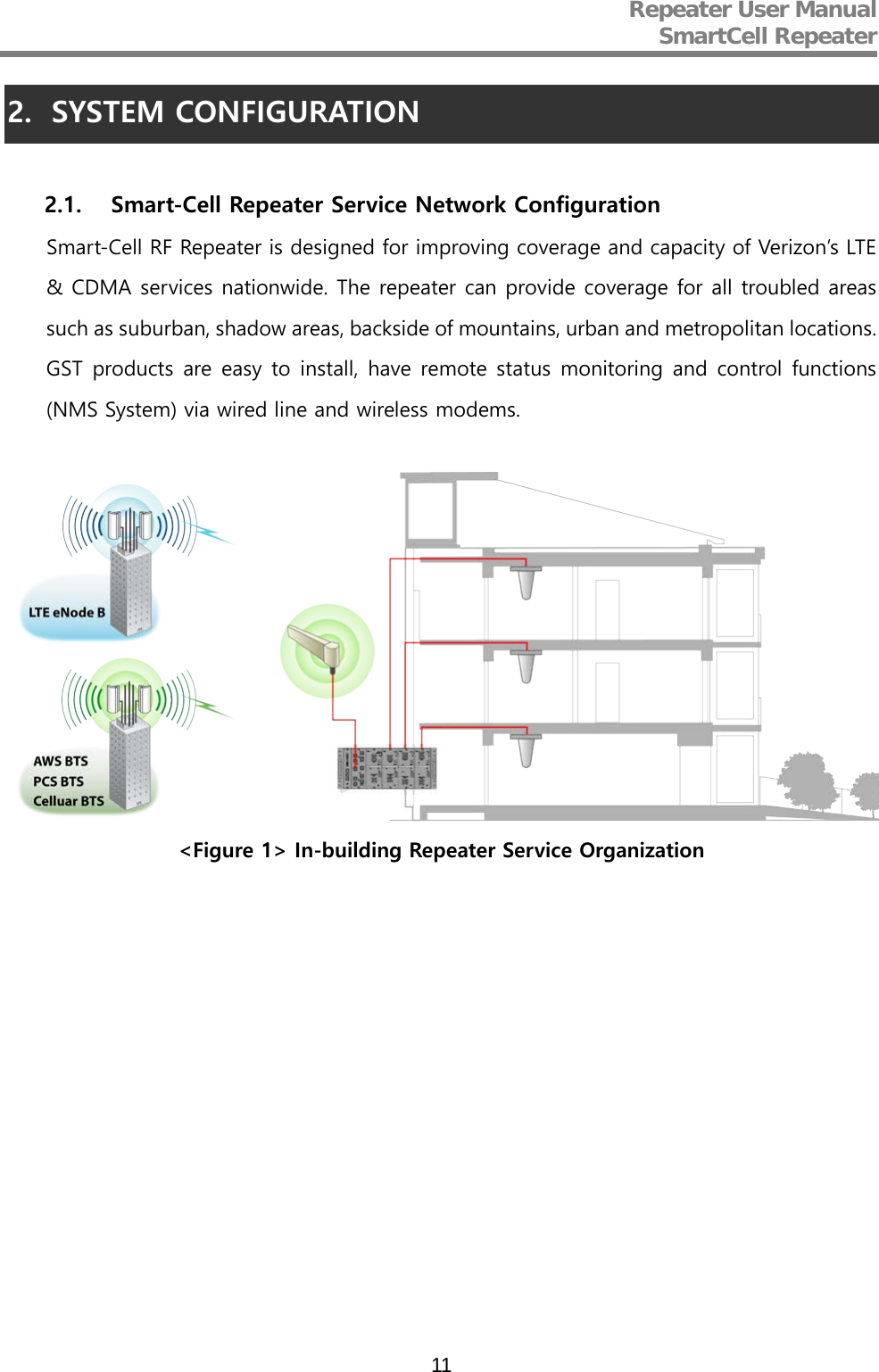
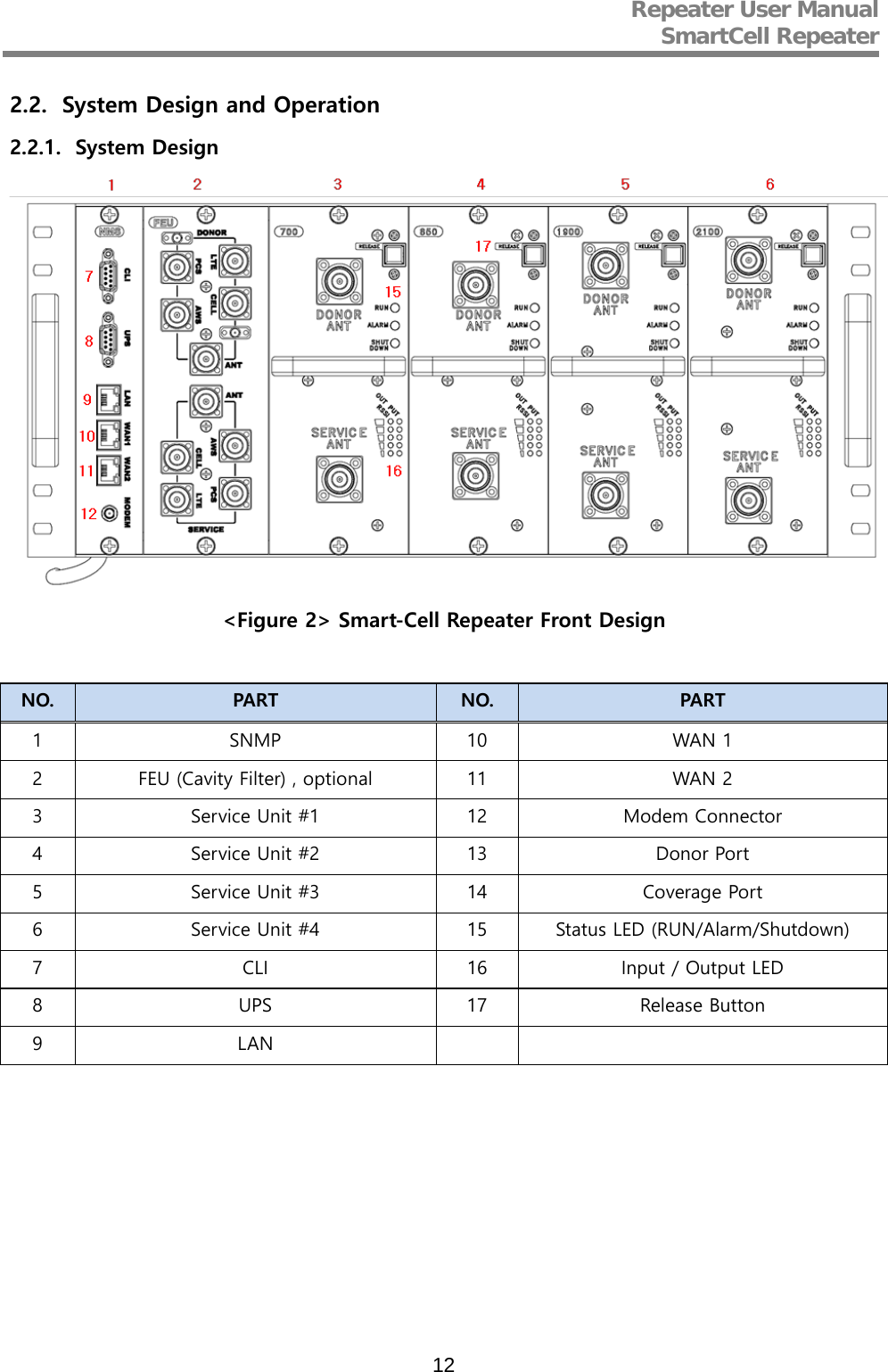
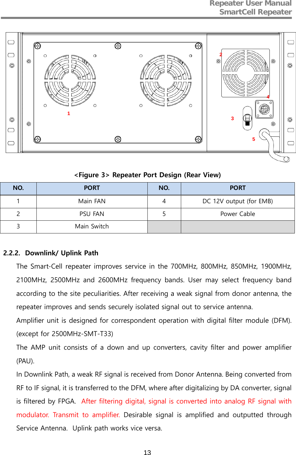
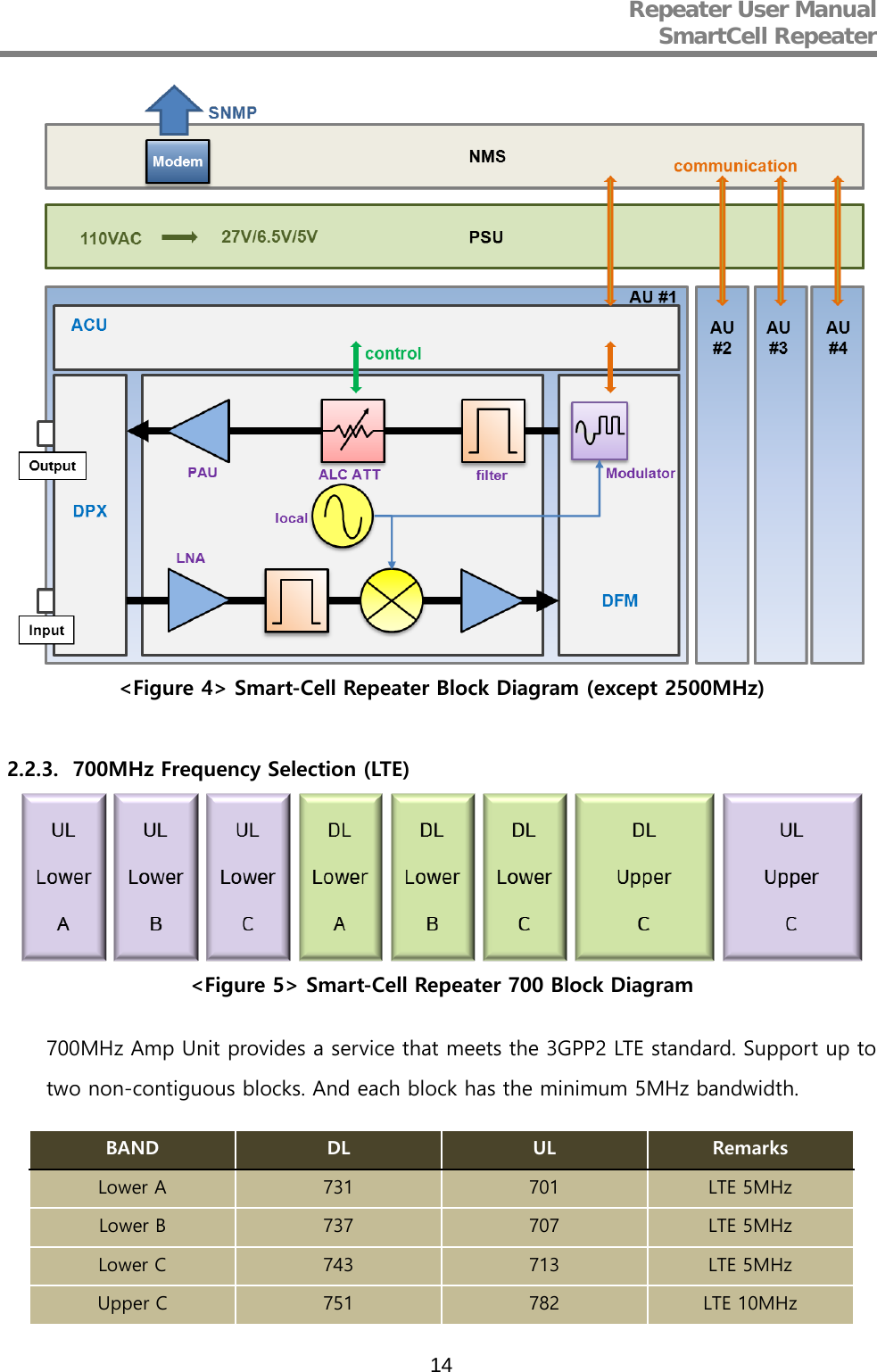
![Repeater User Manual SmartCell Repeater 15 2.2.4. 800MHz Frequency Selection (iDEN) <Figure 6> Smart-Cell Repeater 800 Block Diagram 800MHz Amp Unit has service Cellular 1FA and provides LTE 5MHz (25RB) by default. On / Off control of the service Block is possible. Each block‘s bandwidth are as follows. (CDMA[UL] – 1.25MHz, LTE[UL] – 4.505MHz, CDMA[DL] – 1.25MHz, LTE[DL] – 4.505MHz) 2.2.5. 850MHz Frequency Selection (Cellular) <Figure 7> Smart-Cell Repeater 850 Block Diagram 850MHz Cellular service provides by default, and supports up to two non-contiguous blocks. Each block‘s bandwidth are as follows, and it is possible to choose any combination of any band. (A1 - 11MHz, B1 - 10MHz, A2 - 1.5MHz, B2 - 2.5MHz.) 2.2.6. 1900MHz Frequency Selection (PCS) <Figure 8> 1900MHz Band Frequency](https://usermanual.wiki/GS-Instech/SMT-T33/User-Guide-3104729-Page-15.png)
![Repeater User Manual SmartCell Repeater 16 1900MHz AMP Unit is basically complied with PCS Band block, where maximum three non-contiguous filtering configurations are available. Each sub block is adjustable per 1.25MHz bandwidth step up to 20MHz. Following table shows user selectable channel numbers. BAND DL CENTER [MHz] CHANNEL BAND DL CENTER [MHz] CHANNEL A A1 1931.25 25 guard 1965 700 1932.5 50 E 1966.25 725 1933.75 75 1967.5 750 guard 1935 100 1968.75 775 A2 1936.25 125 guard 1970 800 1937.5 150 F 1971.25 825 1938.75 175 1972.5 850 guard 1940 200 1973.75 875 A3 1941.25 225 guard 1975 900 1942.5 250 C C1 1976.25 925 1943.75 275 1977.5 950 guard 1945 300 1978.75 975 D 1946.25 325 guard 1980 1000 1947.5 350 C2 1981.25 1025 1948.75 375 1982.5 1050 guard 1950 400 1983.75 1075 B B1 1951.25 425 guard 1985 1100 1952.5 450 C3 1986.25 1125 1953.75 475 1987.5 1150 guard 1955 500 1988.75 1175 B2 1956.25 525 1957.5 550 1958.75 575 guard 1960 600 B3 1961.25 625 1962.5 650 1963.75 675](https://usermanual.wiki/GS-Instech/SMT-T33/User-Guide-3104729-Page-16.png)