GS Instech SMT-T33 LTE In-Building RF Repeater User Manual SMT T33 Smart Cell manual V1 3 Rev 1
GS Instruments Co., Ltd. LTE In-Building RF Repeater SMT T33 Smart Cell manual V1 3 Rev 1
SMT-T33_Smart Cell manual V1.3_Rev.1
Smart-Cell Repeater
User Manual
33dBm
April, 2016
Version 1.2

Repeater User Manual
SmartCell Repeater
2
- INDEX -
1. INTRODUCTION .................................................................................................................................................... 4
1.1. Warning ................................................................................................................................................................ 4
1.1.1 FCC Warning Statements..................................................................................................................... 4
1.1.2. IC Warning state ..................................................................................................................................... 6
1.1.3. etc. ................................................................................................................................................................. 8
1.2. GST Smart-Cell Repeater Advantages .................................................................................................... 9
1.3. Repeater Operation ........................................................................................................................................ 9
1.4. Abbreviation ..................................................................................................................................................... 10
2. SYSTEM CONFIGURATION .............................................................................................................................. 11
2.1. Smart-Cell Repeater Service Network Configuration .................................................................... 11
2.2. System Design and Operation ................................................................................................................. 12
2.2.1. System Design ........................................................................................................................................ 12
2.2.2. Downlink/ Uplink Path ....................................................................................................................... 13
2.2.3. 700MHz Frequency Selection (LTE) .............................................................................................. 14
2.2.4. 800MHz Frequency Selection (iDEN) ........................................................................................... 15
2.2.5. 850MHz Frequency Selection (Cellular) ...................................................................................... 15
2.2.6. 1900MHz Frequency Selection (PCS) ........................................................................................... 15
2.2.7. 2100MHz Frequency Selection (AWS) ......................................................................................... 17
2.2.8. 2600MHz Frequency Selection (BRS) ........................................................................................... 17
2.2.9. 2500MHz Frequency Selection (TD-LTE) .................................................................................... 18
3. SYSTEM SPECIFICATIONS ................................................................................................................................ 20
3.1. RF Performance .............................................................................................................................................. 20
3.2. System Specifications ................................................................................................................................... 21
3.3. Electrical and Environmental Specifications ....................................................................................... 22
3.4. Functions ........................................................................................................................................................... 22
4. SETUP ....................................................................................................................................................................... 25
4.1. Equipment Needed for Repeater Setup .............................................................................................. 25
4.1.1. Check points before turning on the Repeater ........................................................................ 25
4.1.2. Open for Service ................................................................................................................................... 26
4.1.3. Signal Strength LED Check ............................................................................................................... 27
4.2. Setting up the Repeater ............................................................................................................................. 28

Repeater User Manual
SmartCell Repeater
3
4.2.1. Quick GUI/Configuration ................................................................................................................... 28
4.2.2. Quick Setup ............................................................................................................................................. 28
4.3. Web UI Ranges Table ................................................................................................................................... 29
4.4. Troubleshooting .............................................................................................................................................. 30
4.4.1. Simple Troubleshooting Method ................................................................................................... 30
4.4.2. Alarm Information ................................................................................................................................ 30
4.4.3. Troubleshooting Guide Related to RF ......................................................................................... 33
4.4.4. Troubleshooting Guide Related to NMS .................................................................................... 38

Repeater User Manual
SmartCell Repeater
4
1. INTRODUCTION
SmartCell is a repeater, which has been designed to improve signals in blanket/shadow
areas inside of buildings to transmit Provider’s variety frequencies. User may choose
filtering configuration according to the specific site circumstances.
1.1. Warning
1.1.1 FCC Warning Statements
1) FCC Part 15.19 :
This device complies with Part 15 of the FCC Rules. Operation is subject to the
following two conditions:
(1) This device may not cause harmful interference, and
(2) This device must accept any interference received, including interference that
may cause undesired operation.
2) FCC Part 15.105 :
This equipment has been tested and found to comply with the limits for a Class A
digital device, pursuant to part 15 of the FCC Rules. These limits are designed to
provide reasonable protection against harmful interference when the equipment is
operated in a commercial environment. This equipment generates, uses, and can
radiate radio frequency energy and, if not installed and used in accordance with the
instruction manual, may cause harmful interference to radio communications.
Operation of this equipment in a residential area is likely to cause harmful
interference in which case the user will be required to correct the interference at his
expense.
3) FCC Part 15.21 :
Any changes or modifications not expressly approved by the party responsible for
compliance could void the user's authority to operate this equipment.
4) FCC Part 27.5

Repeater User Manual
SmartCell Repeater
5
Antennas must be installed in accordance with FCC 27.50 and SRSP 518.
Please note that EIRP based on antenna gain after accounting for cable loss should
be less than 50 Watt (47 dBm) for Donor side. For Service side, with 3dBi gain antennas
the height of the antenna above average terrain (HAAT) must not exceed 14.496 m.
For different gain antennas refer to the relevant rules.
5) FCC Warning Label
WARNING. This is NOT a CONSUMER device. It is designed for installation by FCC LICENSE
and QUALIFIED INSTALLERS. You MUST have an FCC LICENSE or express consent of an FCC
Licensee to operate this device.
Unauthorized use may result in significant forfeiture penalties, including penalties in excess
of $100,000 for each continuing violation.

Repeater User Manual
SmartCell Repeater
6
1.1.2. IC Warning state
1) RSS-GEN, Sec. 7.1.2 – (transmitters)
Under Industry Canada regulations, this radio transmitter may only operate using an antenna
of a type and maximum (or lesser) gain approved for the transmitter by Industry Canada. To
reduce potential radio interference to other users, the antenna type and its gain should be so
chosen that the equivalent isotropically radiated power (e.i.r.p.) is not more than that necessary
for successful communication.
Conformément à la réglementation d’Industrie Canada, le présent émetteur radio peut
fonctionneravec une antenne d’un type et d’un gain maximal (ou inférieur) approuvé pour
l’émetteur par Industrie Canada.
Dans le but de réduire les risques de brouillage radioélectrique à l’intention desautres
utilisateurs,
il faut choisir le type d’antenne et son gain de sorte que la puissance isotroperayonnée
quivalente (p.i.r.e.) ne dépassepas l’intensité nécessaire à l’établissement d’une communication
satisfaisante.
2) RSS-GEN, Sec. 7.1.2 – (detachable antennas)
This radio transmitter (identify the device by certification number, or model number if
Category II)has been approved by Industry Canada to operate with the antenna types listed
below with the maximum permissible gain and required antenna impedance for each antenna
type indicated. Antenna types not included in this list, having a gain greater than the maximum
gain indicated for that type, are strictly prohibited for use with this device.

Repeater User Manual
SmartCell Repeater
7
Le présent émetteur radio (identifier le dispositif par son numéro de certification ou son
numéro de modèle s’il fait partie du matériel de catégorie I) a été approuvé par Industrie
Canada pour fonctionner avec les types d’antenne énumérés ci-dessous et ayant un gain
admissible maximal et l’impédance requise pour chaque type d’antenne. Les types d’antenne
non inclus dans cette liste,ou dont le gain est supérieur au gain maximal indiqué, sont
strictement interdits pour l’exploitation de l’émetteur.
3) RSS-131 Section 5.3 User Manual
The user manual shall contain the following information on the enhancer:
a. The nominal passband gain (dB);
b. The nominal bandwidth;
c. The rated mean output power;
d. The input and output impedances, and;
The following notice: "The Manufacturer's rated output power of this equipment is for single
carrier operation. For situations when multiple carrier signals are present, the rating would
have to be reduced by 3.5 dB, especially where the output signal is re-radiated and can cause
interference to adjacent band users. This power reduction is to be by means of input power
or gain reduction and not by an attenuator at the output of the device."
4) RF Radiation Exposure
This equipment complies with RF radiation exposure limits set forth for an uncontrolled
environment. This equipment should be installed and operated with a minimum distance of
at least 100 cm with 15dBi antenna gain between the radiator and your body. This transmitter

Repeater User Manual
SmartCell Repeater
8
must not be co-located or operating in conjunction with any other antenna or transmitter. RF
exposure will be addressed at time of installation and the use of higher gain antennas require
larger separation distances.
5) RSS-102 RF Exposure
L'antenne du donneur a une antenne 15dBi gain.Antenna doit être installé pour maintenir en tout
temps un minimum de distance d'au moins 100 cm entre la source de rayonnement (antenne) et
toute personne physique.
Cet appareil ne doit pas être installé ou utilisé en conjonction avec une autre antenne ou émetteur.
1.1.3. etc.
1) Use of unauthorized antennas, cables, and/or coupling devices not conforming with
ERP/EIRP and/or indoor-only restrictions is prohibited.)
2) Home/ personal use are prohibited.
Repeater User Manual
SmartCell Repeater
9
1.2. GST Smart-Cell Repeater Advantages
It provides selectable RF power levels for any wireless technology / band.
It has individual monitoring multiple technology.
FPGA digital filtering provides optimized RF performance.
It allows modification of technology via customer interface.
It is easily installed.
Frequency is easy to add / delete / change.
It has scalable single and multi-service design.
Customer data service is improved by adding 4G (LTE)
It meets all Verizon’s technology requirements.
It guarantees 5 year warranty for all individual components.
Its modular design is a customer friendly and efficient.
1.3. Repeater Operation
Simple replacing of the amplifier unit allows changing the service. Smart-Cell repeater
provides service at 700MHz, 800MHz, 850MHz, 1900MHz, 2100MHz, 2500MHz and
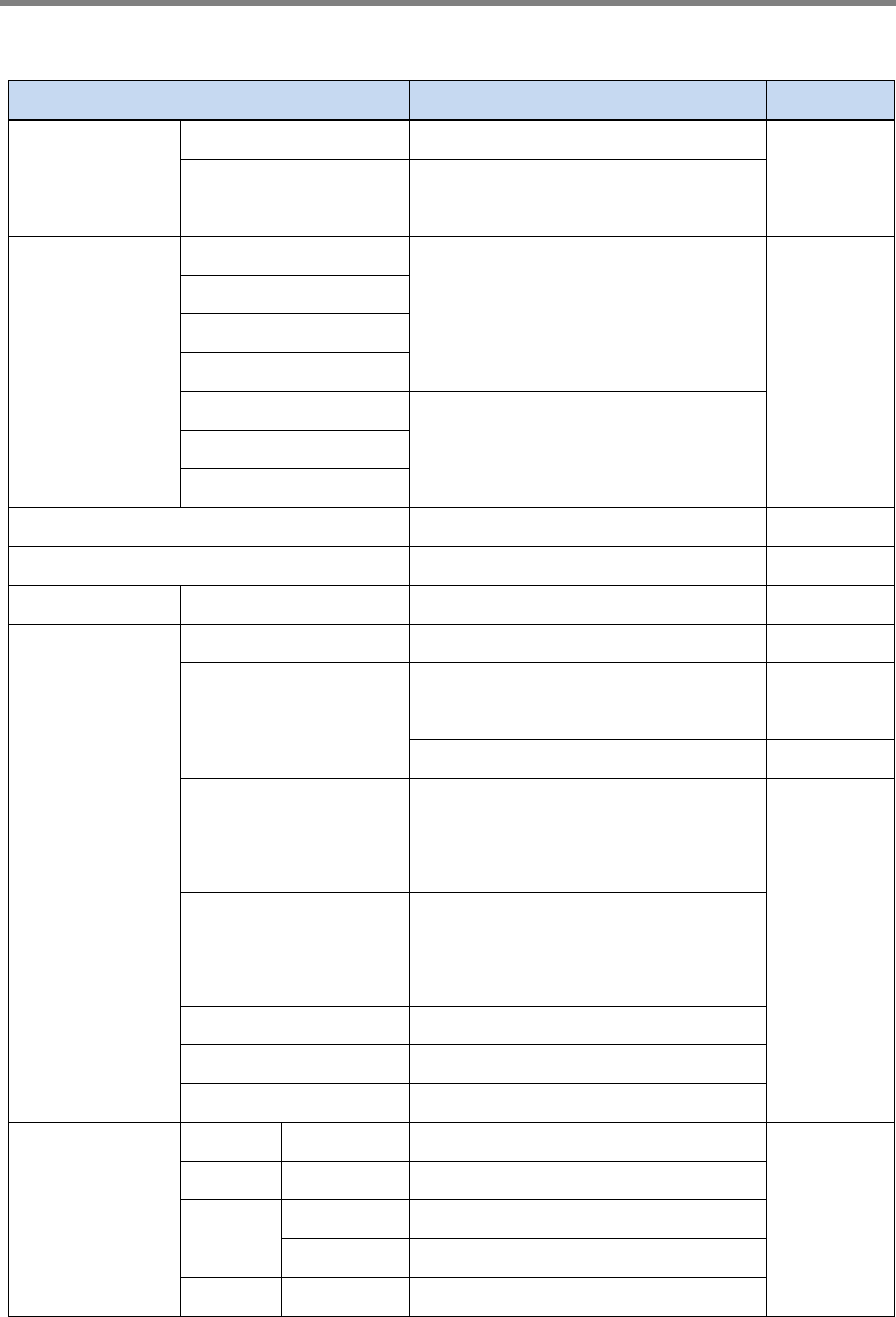
2600MHz. One PSU supplies electricity to maximum 4 amplifier units
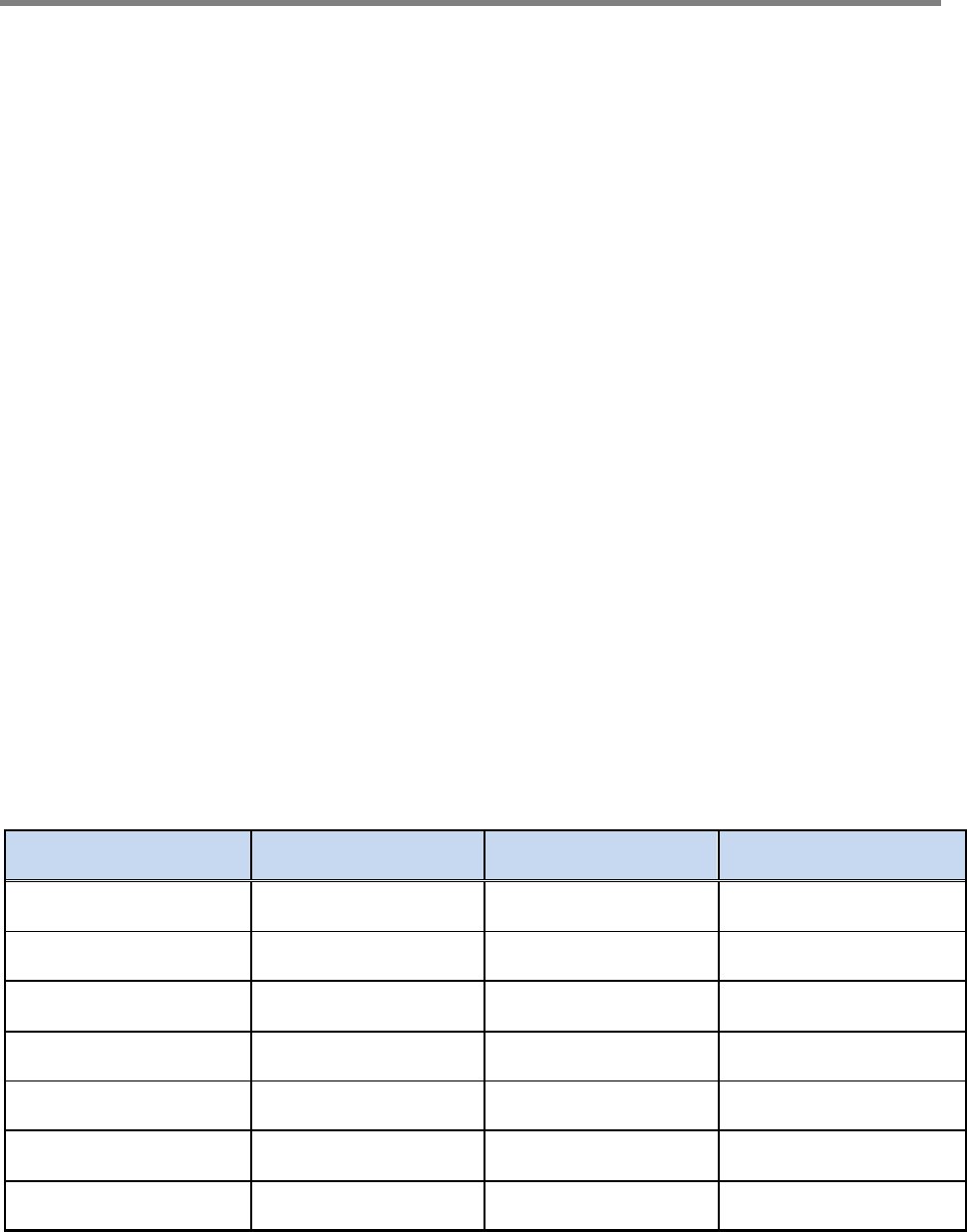
Frequency Service Device Name Remarks
700 LTE SMT-L33
800 iDEN SMT-I33
850 Cellular SMT-C33
1900 PCS SMT-P33
2100 AWS SMT-A33
2500 TD-LTE SMT-T33
2600 BRS SMT-B33
Repeater User Manual
SmartCell Repeater
10
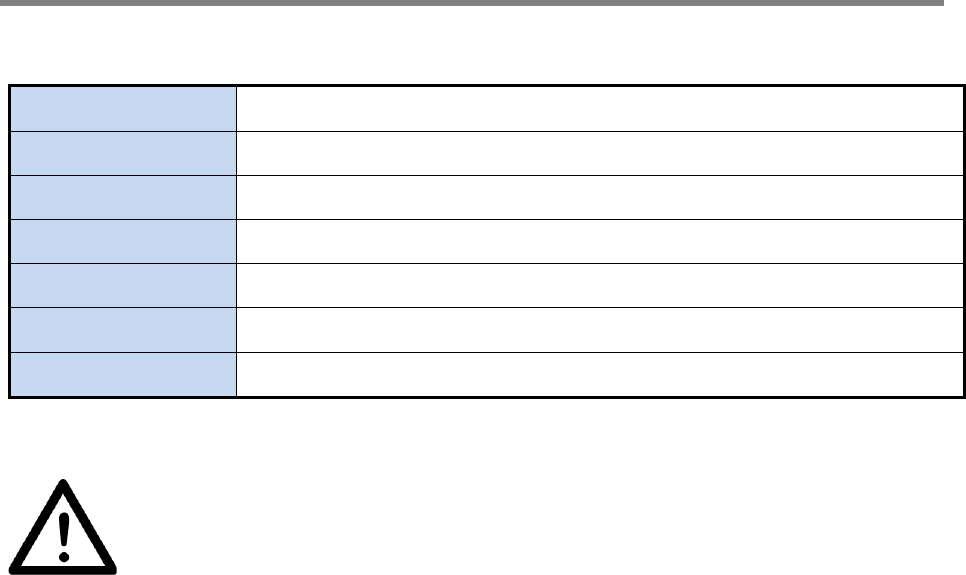
1.4. Abbreviation
DFM Digital Filter Module
PSU Power Supply Unit
ALC Auto Level Control
SNMP Simple Network Management Protocol
AOC Auto Oscillation Check
SDM Synchronous Detect Module
Caution: Risk of explosion if battery on the controller board is replaced by
incorrect type.
Repeater User Manual
SmartCell Repeater
11
2. SYSTEM CONFIGURATION
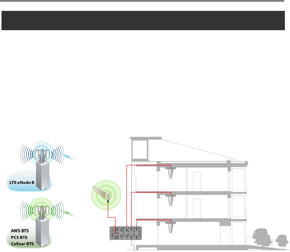
2.1. Smart-Cell Repeater Service Network Configuration
Smart-Cell RF Repeater is designed for improving coverage and capacity of Verizon’s LTE
& CDMA services nationwide. The repeater can provide coverage for all troubled areas
such as suburban, shadow areas, backside of mountains, urban and metropolitan locations.
GST products are easy to install, have remote status monitoring and control functions
(NMS System) via wired line and wireless modems.
<Figure 1> In-building Repeater Service Organization
Repeater User Manual
SmartCell Repeater
12
2.2. System Design and Operation
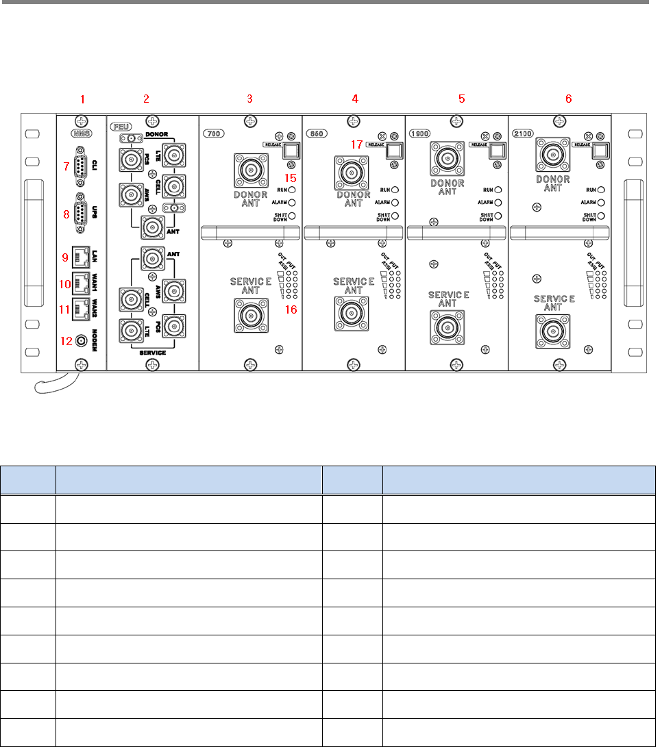
2.2.1. System Design
<Figure 2> Smart-Cell Repeater Front Design
NO. PART NO. PART
1 SNMP 10 WAN 1
2 FEU (Cavity Filter) , optional 11 WAN 2
3 Service Unit #1 12 Modem Connector
4 Service Unit #2 13 Donor Port
5 Service Unit #3 14 Coverage Port
6 Service Unit #4 15 Status LED (RUN/Alarm/Shutdown)
7 CLI 16 Input / Output LED
8 UPS 17 Release Button
9 LAN
Repeater User Manual
SmartCell Repeater
13
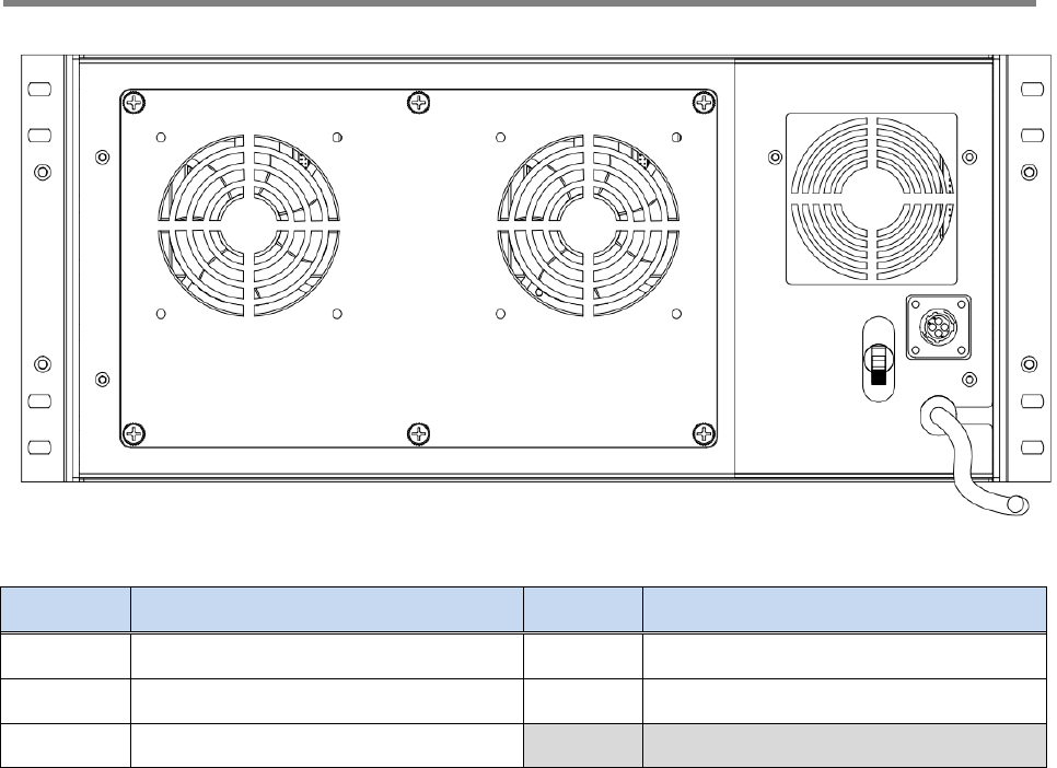
<Figure 3> Repeater Port Design (Rear View)
NO. PORT NO. PORT
1 Main FAN 4 DC 12V output (for EMB)
2 PSU FAN 5 Power Cable
3 Main Switch
2.2.2. Downlink/ Uplink Path
The Smart-Cell repeater improves service in the 700MHz, 800MHz, 850MHz, 1900MHz,
2100MHz, 2500MHz and 2600MHz frequency bands. User may select frequency band
according to the site peculiarities. After receiving a weak signal from donor antenna, the
repeater improves and sends securely isolated signal out to service antenna.
Amplifier unit is designed for correspondent operation with digital filter module (DFM).
(except for 2500MHz-SMT-T33)
The AMP unit consists of a down and up converters, cavity filter and power amplifier
(PAU).
In Downlink Path, a weak RF signal is received from Donor Antenna. Being converted from
RF to IF signal, it is transferred to the DFM, where after digitalizing by DA converter, signal
is filtered by FPGA. After filtering digital, signal is converted into analog RF signal with
modulator. Transmit to amplifier. Desirable signal is amplified and outputted through
Service Antenna. Uplink path works vice versa.
1
2
3
5
4
Repeater User Manual
SmartCell Repeater
14
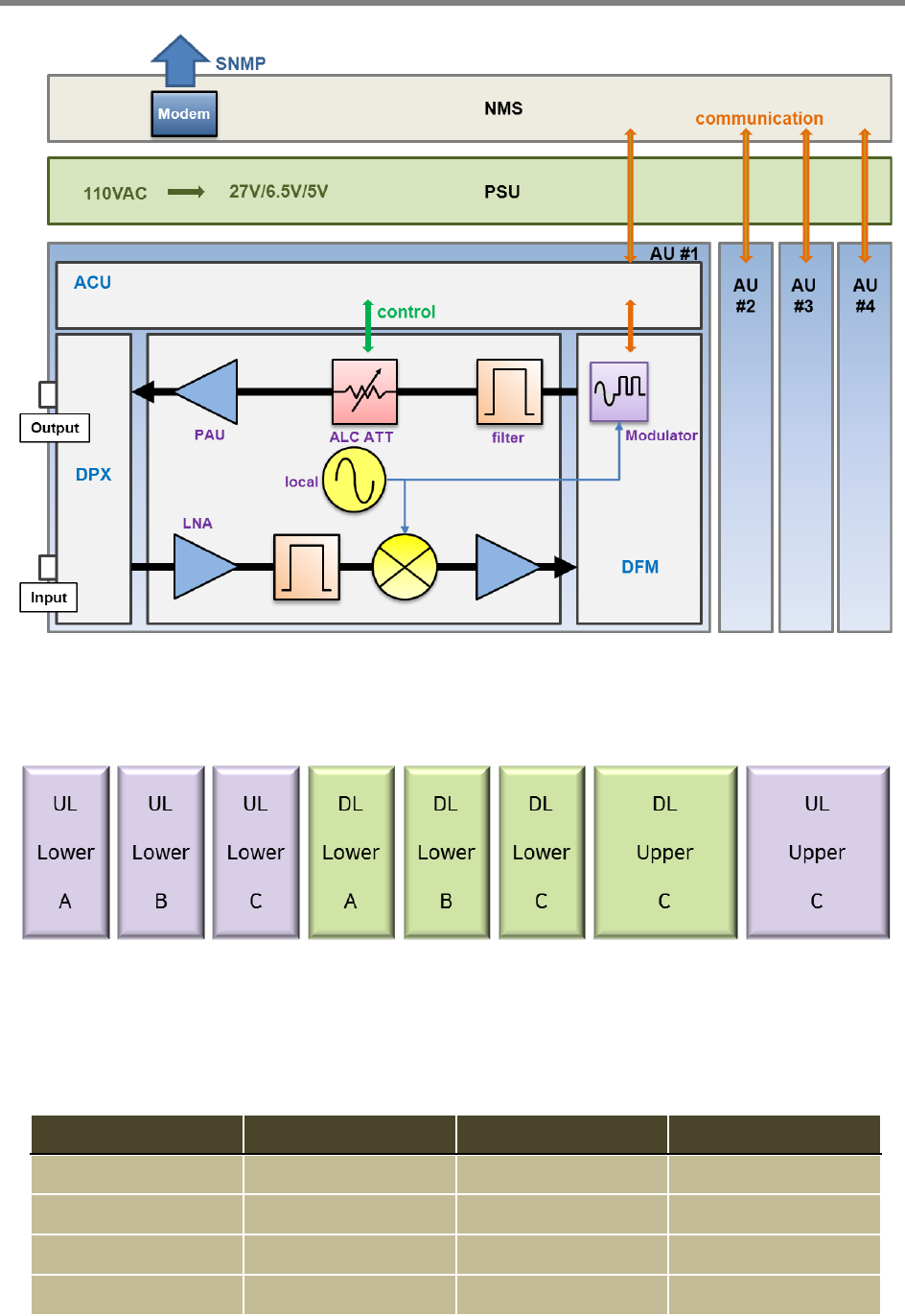
<Figure 4> Smart-Cell Repeater Block Diagram (except 2500MHz)
2.2.3. 700MHz Frequency Selection (LTE)
<Figure 5> Smart-Cell Repeater 700 Block Diagram
700MHz Amp Unit provides a service that meets the 3GPP2 LTE standard. Support up to
two non-contiguous blocks. And each block has the minimum 5MHz bandwidth.
BAND DL UL Remarks
Lower A 731 701 LTE 5MHz
Lower B 737 707 LTE 5MHz
Lower C 743 713 LTE 5MHz
Upper C 751 782 LTE 10MHz
Repeater User Manual
SmartCell Repeater
15
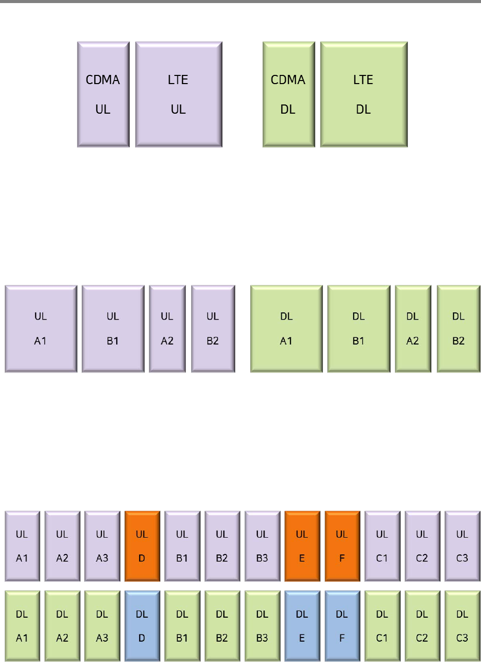
2.2.4. 800MHz Frequency Selection (iDEN)
<Figure 6> Smart-Cell Repeater 800 Block Diagram
800MHz Amp Unit has service Cellular 1FA and provides LTE 5MHz (25RB) by default. On
/ Off control of the service Block is possible. Each block‘s bandwidth are as follows.
(CDMA[UL] – 1.25MHz, LTE[UL] – 4.505MHz, CDMA[DL] – 1.25MHz, LTE[DL] – 4.505MHz)
2.2.5. 850MHz Frequency Selection (Cellular)
<Figure 7> Smart-Cell Repeater 850 Block Diagram
850MHz Cellular service provides by default, and supports up to two non-contiguous
blocks. Each block‘s bandwidth are as follows, and it is possible to choose any
combination of any band. (A1 - 11MHz, B1 - 10MHz, A2 - 1.5MHz, B2 - 2.5MHz.)
2.2.6. 1900MHz Frequency Selection (PCS)
<Figure 8> 1900MHz Band Frequency
Repeater User Manual
SmartCell Repeater
16
1900MHz AMP Unit is basically complied with PCS Band block, where maximum three
non-contiguous filtering configurations are available. Each sub block is adjustable per
1.25MHz bandwidth step up to 20MHz. Following table shows user selectable channel
numbers.
BAND DL CENTER
[MHz] CHANNEL BAND DL CENTER
[MHz] CHANNEL
A
A1
1931.25 25 guard 1965 700
1932.5 50
E
1966.25 725
1933.75 75 1967.5 750
guard 1935 100 1968.75 775
A2
1936.25 125 guard 1970 800
1937.5 150
F
1971.25 825
1938.75 175 1972.5 850
guard 1940 200 1973.75 875
A3
1941.25 225 guard 1975 900
1942.5 250
C
C1
1976.25 925
1943.75 275 1977.5 950
guard 1945 300 1978.75 975
D
1946.25 325 guard 1980 1000
1947.5 350
C2
1981.25 1025
1948.75 375 1982.5 1050
guard 1950 400 1983.75 1075
B
B1
1951.25 425 guard 1985 1100
1952.5 450
C3
1986.25 1125
1953.75 475 1987.5 1150
guard 1955 500 1988.75 1175
B2
1956.25 525
1957.5 550
1958.75 575
guard 1960 600
B3
1961.25 625
1962.5 650
1963.75 675
Repeater User Manual
SmartCell Repeater
17
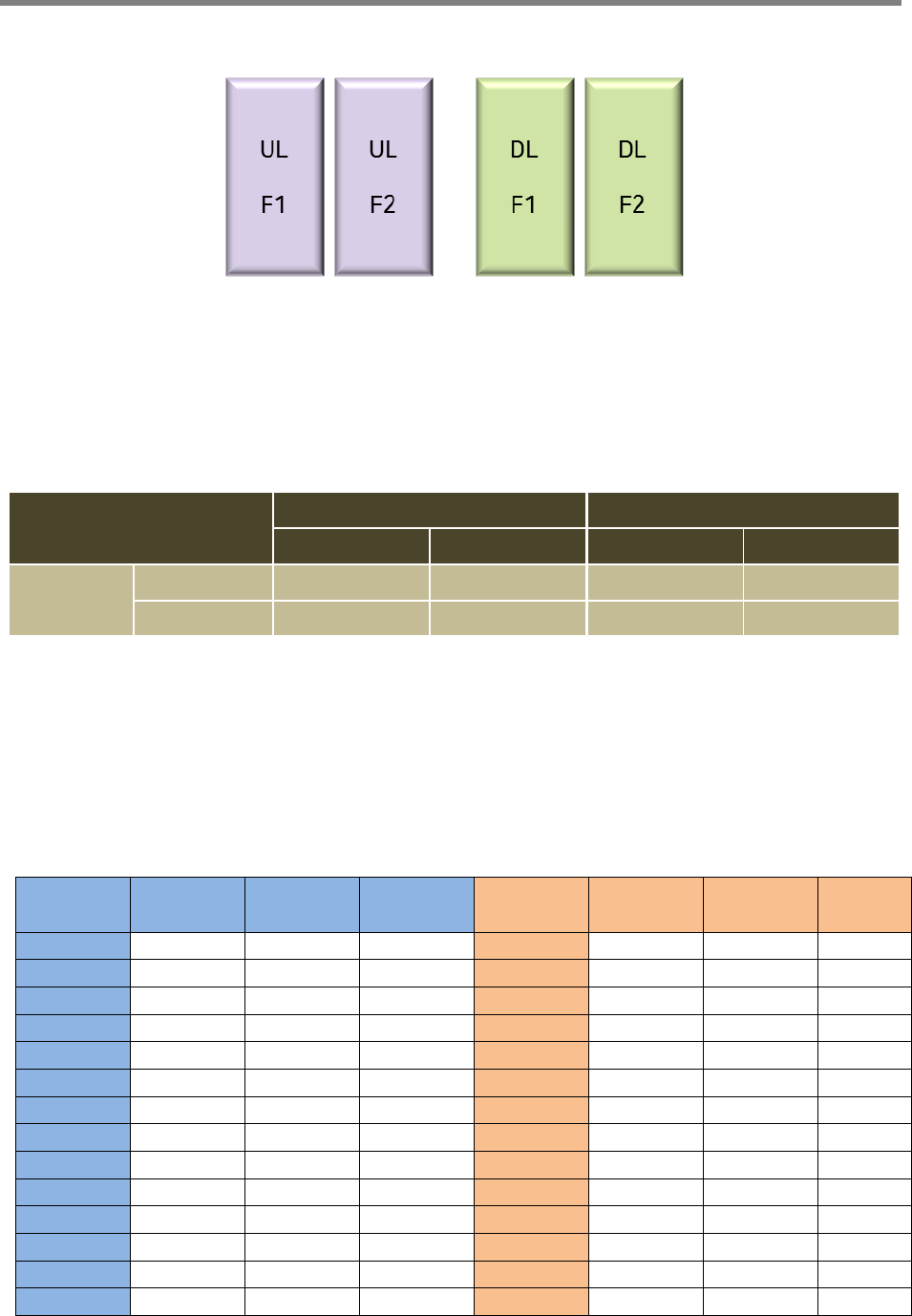
2.2.7. 2100MHz Frequency Selection (AWS)
<Figure 7> 2100MHz Band Frequency
2100 Amp Unit has basically satisfies the CDMA standard, and supports non-contiguous
2 block. If you select “contiguous button”, Web UI has select the contiguous F band.
And you don’t select “Contiguous button”, Web UI has select the each band of F1 and
F2. Frequency range of each band as follows.
BAND
Downlink Uplink
Start Stop Start Stop
F
F1 2145.15 2149.85 1745.15 1749.85
F2 2150.15 2154.85 1750.15 1754.85
2.2.8. 2600MHz Frequency Selection (BRS)
2600MHz AMP Unit is basically complied with Band block, where maximum two non-contiguous
filtering configurations are available. Each sub block is adjustable per 5MHz bandwidth step up to
40MHz.
RF
Downlink
Center
Frequency start stop RF
Uplink
Center
Frequency start stop
A1' 2622.5 2620 2625 A1 2502.5 2500 2505
A2' 2627.5 2625 2630 A2 2507.5 2505 2510
A3' 2632.5 2630 2635 A3 2512.5 2510 2515
A4' 2637.5 2635 2640 A4 2517.5 2515 2520
A5' 2642.5 2640 2645 A5 2522.5 2520 2525
A6' 2647.5 2645 2650 A6 2527.5 2525 2530
A7' 2652.5 2650 2655 A7 2532.5 2530 2535
A8' 2657.5 2655 2660 A8 2537.5 2535 2540
A9' 2662.5 2660 2665 A9 2542.5 2540 2545
A10' 2667.5 2665 2670 A10 2547.5 2545 2550
A11' 2672.5 2670 2675 A11 2552.5 2550 2555
A12' 2677.5 2675 2680 A12 2557.5 2555 2560
A13' 2682.5 2680 2685 A13 2562.5 2560 2565
A14' 2687.5 2685 2690 A14 2567.5 2565 2570
Repeater User Manual
SmartCell Repeater
18
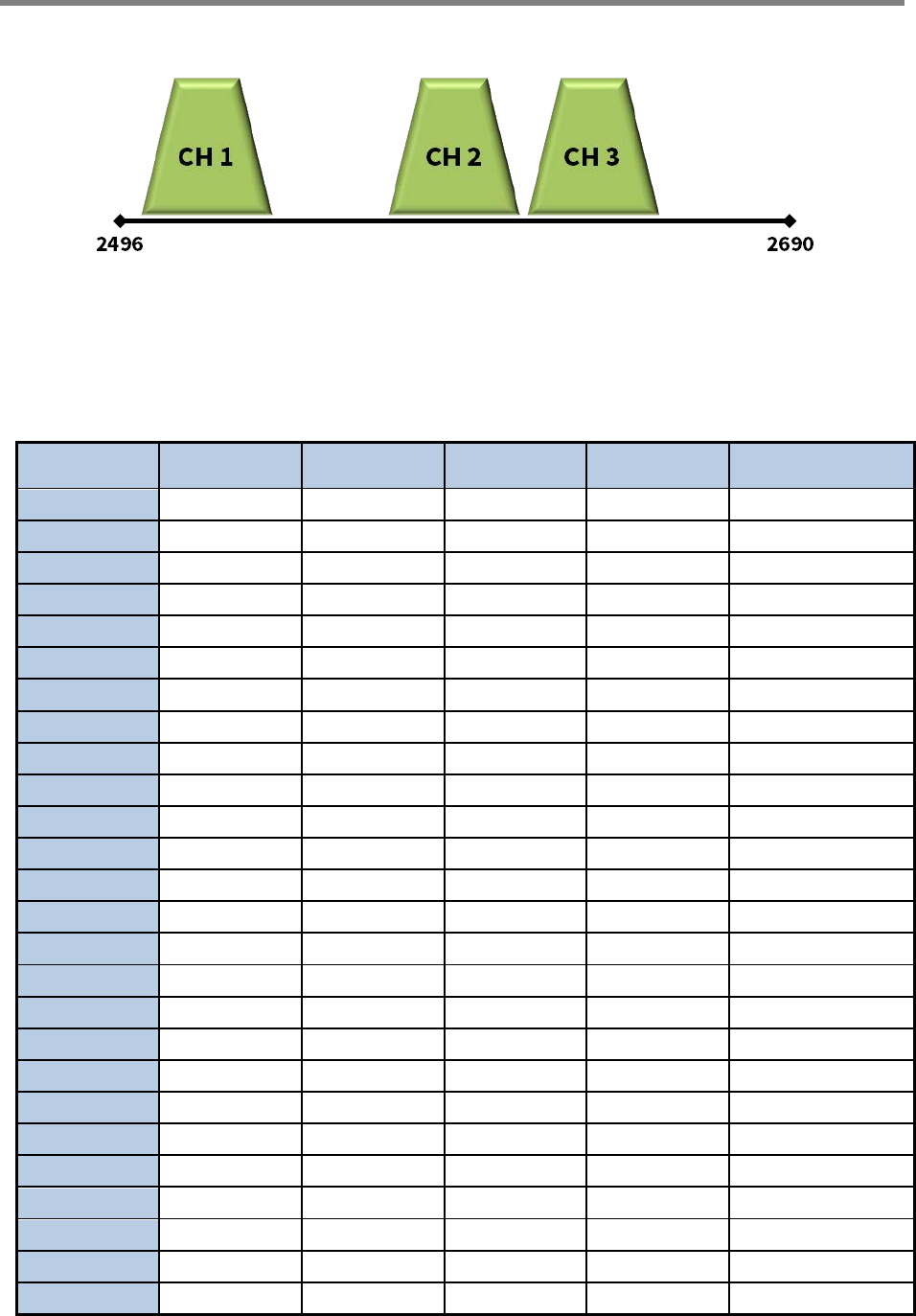
2.2.9. 2500MHz Frequency Selection (TD-LTE)
2500MHz AMP Unit is basically complied with LTE Band block 41, where maximum three
non-contiguous filtering configurations are available. Following table shows user selectable
channel numbers.
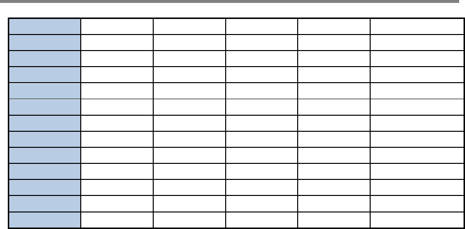
Ch. Name Start Center Stop Bandwidth Regulatory Ch.
L01 2497.80 2506.80 2515.80 18.00 BRS1,A1,A2,A3
L09 2501.30 2510.30 2519.30 18.00 BRS1,A1,A2,A3,B1
L16 2504.60 2513.60 2522.60 18.00 A1,A2,A3,B1
L23 2507.80 2516.80 2525.80 18.00 A1,A2,A3,B1,B2
L30 2511.10 2520.10 2529.10 18.00 A2,A3,B1,B2,B3
L35 2514.60 2523.60 2532.60 18.00 A3,B1,B2,B3
L02 2517.60 2526.60 2535.60 18.00 A3,B1,B2,B3,C1
L10 2521.10 2530.10 2539.10 18.00 B1,B2,B3,C1
L17 2524.40 2533.40 2542.40 18.00 B1,B2,B3,C1,C2
L24 2527.60 2536.60 2545.60 18.00 B2,B3,C1,C2,C3
L31 2530.90 2539.90 2548.90 18.00 B3,C1,C2,C3
L36 2534.40 2543.40 2552.40 18.00 B3,C1,C2,C3,D1
L03 2537.40 2546.40 2555.40 18.00 C1,C2,C3,D1
L11 2540.90 2549.90 2558.90 18.00 C1,C2,C3,D1,D2
L18 2544.20 2553.20 2562.20 18.00 C2,C3,D1,D2,D3
L25 2547.40 2556.40 2565.40 18.00 C3,D1,D2,D3
L04 2574.10 2583.10 2592.10 18.00 A4,B4,C4,D4
L12 2578.10 2587.10 2596.10 18.00 A4,B4,C4,D4,G4
L19 2582.10 2591.10 2600.10 18.00 B4,C4,D4,G4
L26 2584.00 2593.00 2602.00 18.00 B4,C4,D4,G4,F4
L32 2586.10 2595.10 2604.10 18.00 C4,D4,G4,F4
L37 2589.90 2598.90 2607.90 18.00 C4,D4,G4,F4,E4
L05 2593.90 2602.90 2611.90 18.00 D4,G4,F4,E4
L06 2619.80 2628.80 2637.80 18.00 BRS2,E1,E2,E3
L13 2623.30 2632.30 2641.30 18.00 BRS2,E1,E2,E3,F1
L20 2626.60 2635.60 2644.60 18.00 E1,E2,E3,F1
Repeater User Manual
SmartCell Repeater
19
L27 2629.80 2638.80 2647.80 18.00 E1,E2,E3,F1,F2
L33 2633.10 2642.10 2651.10 18.00 E2,E3,F1,F2,F3
L38 2636.60 2645.60 2654.60 18.00 E3,F1,F2,F3
L07 2639.60 2648.60 2657.60 18.00 E3,F1,F2,F3,H1
L14 2643.10 2652.10 2661.10 18.00 F1,F2,F3,H1
L21 2646.40 2655.40 2664.40 18.00 F1,F2,F3,H1,H2
L28 2649.60 2658.60 2667.60 18.00 F2,F3,H1,H2,H3
L34 2652.90 2661.90 2670.90 18.00 F3,H1,H2,H3
L39 2656.40 2665.40 2674.40 18.00 F3,H1,H2,H3,G1
L08 2659.40 2668.40 2677.40 18.00 H1,H2,H3,G1
L15 2662.90 2671.90 2680.90 18.00 H1,H2,H3,G1,G2
L22 2666.20 2675.20 2684.20 18.00 H2,H3,G1,G2,G3
L29 2669.40 2678.40 2687.40 18.00 H3,G1,G2,G3
Repeater User Manual
SmartCell Repeater
20
3. SYSTEM SPECIFICATIONS
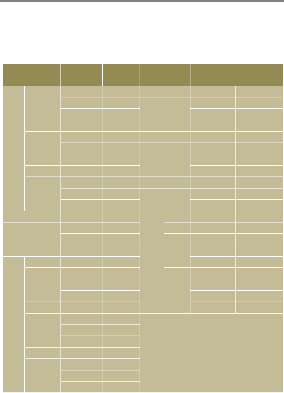
3.1. RF Performance
Item Specification Remark
Frequency
700MHz
DL : 728.5MHz ~ 745.5MHz
746MHz ~ 756MHz
UL : 698.5MHz ~ 715.5MHz
777MHz ~ 787MHz
5MHz / 10MHz
800MHz
DL : 862MHz ~ 863.8MHz
864MHz ~ 868.6MHz
UL : 817MHz ~ 818.8MHz
819MHz ~ 823.6MHz
1.8MHz + 4.8MHz
850MHz DL : 869MHz ~ 894MHz
UL : 824MHz ~ 849MHz 25MHz
1900MHz DL : 1930MHz ~ 1990MHz
UL : 1850MHz ~ 1910MHz 60MHz
2100MHz DL : 2145MHz ~ 2155MHz
UL : 1745MHz ~ 1755MHz 10MHz
2500MHz 2496MHz ~ 2690MHz 194MHz
2600MHz DL : 2620MHz ~ 2690MHz
UL : 2500MHz ~ 2570MHz 70MHz
Maximum Input Power -27dBm
Output Power (ANT Port) +33dBm / 2W Tot al
Repeater User Manual
SmartCell Repeater
21
3.2. System Specifications
Parameter Specification Remark
Gain
Range 60dB ~ 90dB
Adjust Step ±0.5dB
Adjust Accuracy ±1dB
Flatness
700MHz
< 3.0dBp-p
800MHz
2500MHz
2600MHz
850MHz
< 5.0dBp-p
1900MHz
2100MHz
Propagation Delay ≤ 6us
VSWR 1.7 : 1
Noise Figure Max Gain < 7dB
ACP
750MHz > 45dBc @±5MHz/10MHz
800MHz
> 45dBc ±750KHz
> 50dBc@±1.98KHz CDMA
> 45dBc @±5MHz/10MHz LTE
850MHz
> 45 dBc ±885KHz
> 52dBc@±1.98KHz
<-13dBm@Fc±2.25MHz (RBW: 1MHz)
1900MHz
> 45 dBc ±750KHz
> 52dBc@±1.98KHz
<-13dBm@Fc±2.25MHz (RBW: 1MHz)
2100MHz > 45dBc @±5MHz/10MHz
2500MHz > 45dBc @±5MHz/10MHz
2600MHz > 45dBc @±20MHz
Roll off
700MHz ±1MHz > 45dBc
800MHz ±1MHz > 45dBc
850MHz ±1MHz > 45dBc
±250kHz > 30dBc
1900MHz ±1MHz > 50dBc
Repeater User Manual
SmartCell Repeater
22
2100MHz ±1MHz > 40dBc
2500MHz ±1MHz > 50dBc
2600MHz ±1MHz > 50dBc
Characteristic Impedance 50Ω
3.3. Electrical and Environmental Specifications
Item Specification Remark
RF Connector N-Type Female Donor & Server ANT Port
AC Supply AC 110V 60Hz 3.0A
Out Dimension 3.1” x 15.5” x 7.7” AMP unit
19” x 19” x 7.9” System (Rack mount)
Weight
700MHz 13.0lbs 5.89 ㎏
800MHz 11.5lbs 5.21 ㎏
850MHz 11.5lbs 5.21 ㎏
1900MHz 11.5lbs 5.21 ㎏
2100MHz 10.0lbs 4.53 ㎏
2500MHz 12.0lbs 5.44 ㎏
2600MHz 11.5lbs 5.21 ㎏
FEU 23 19” rack + NMS + PSU
(except AMP units and FEU)
Operation Temperature -10℃ ~ +50℃ Convection cooling
Humidity 5% ~ 95% Non-condensing
Vibration Resistance 1G, 10~150Hz
0.1 Octaves/min
MTBF 50,000 hours
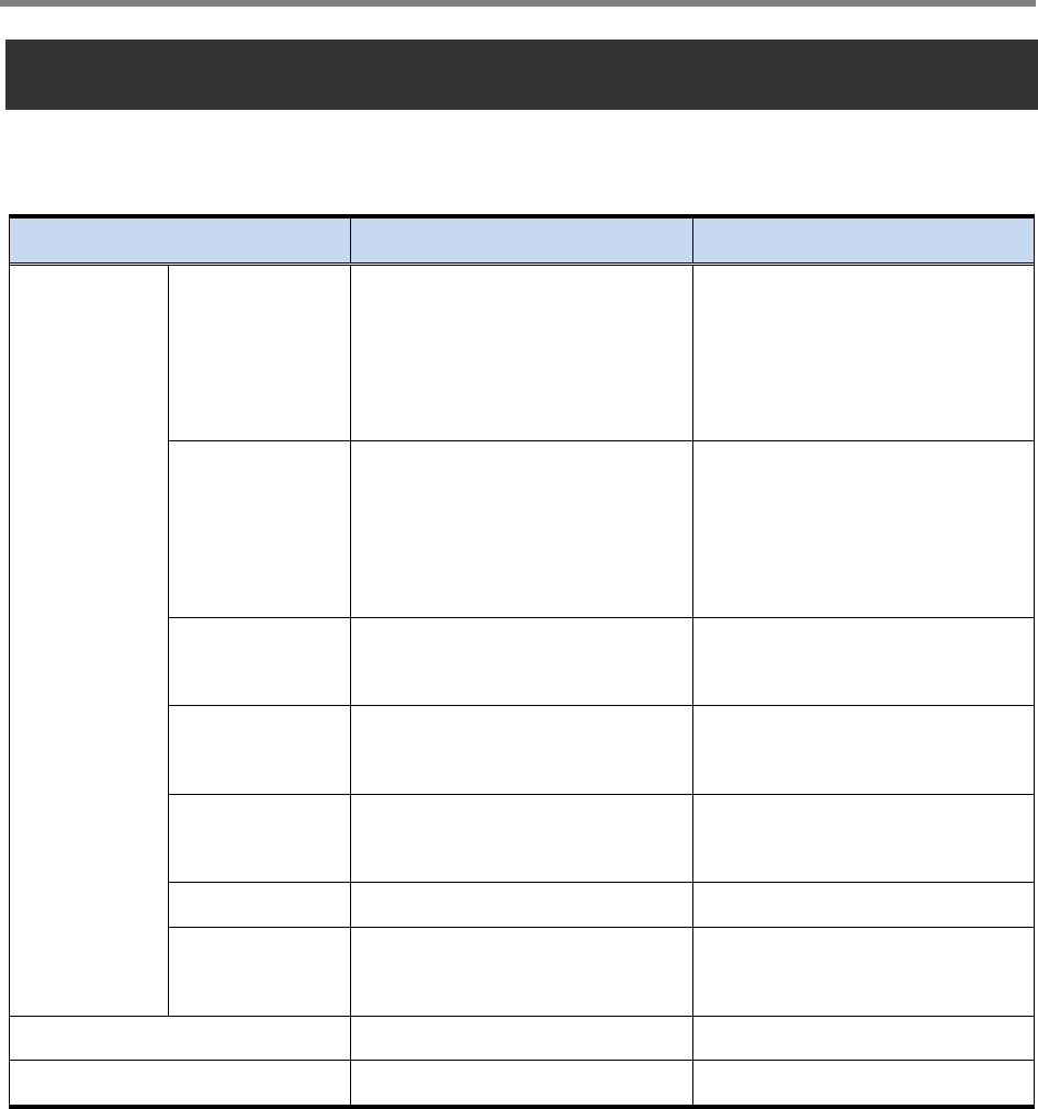
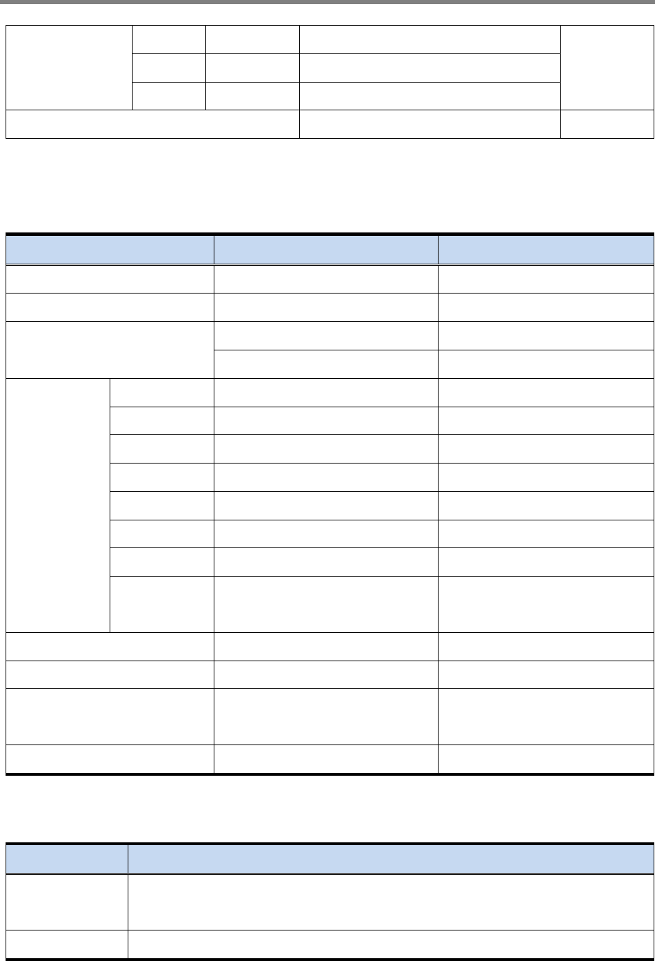
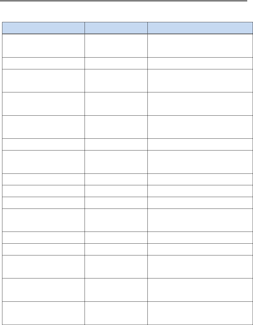
3.4. Functions
Parameter Specification
Gain Control • Adjustable DL and UL Gain range 60dB ~ 90dB.
• Display default Gain and current Gain function
ALC • To limit output powers as far as default range.

Repeater User Manual
SmartCell Repeater
23
Auto Limit
Control
• Used for DAS configuration and when oscillation/isolation is a concern.
• Automatic Gain decrement when output power of repeater is higher than default
level.
• Automatic Gain recovery when output power of repeater is reduced.
• Shutdown when output power is higher than default level in the minimum gain.
• Automatic Recovery Algorithm conversion after shutdown status.
Band Select
• 700MHz : Lower A(5MHz)/Lower B(5MHz)/ Lower C(5MHz)/Upper C(10MHz)
• 800MHz: 5MHz/10MHz
• 850MHz : A1(11MHz)/B1(10MHz)/A2(1.5MHz)/B2(2.5MHz)
• 1900MHz : 1.25MHz ~ 20MHz/1.25MHz step
• 2100MHz: 5MHz/10MHz
• 2500MHz: 20MHz
• 2600MHz: 5MHz/10MHz/15MHz/20MHz
Power
Monitoring • Monitoring repeater’s output level.
Oscillation
Check
• Isolation Check in initial set up or Reset.
• When Oscillation occurred, repeater attempts to stabilize Isolation through Gain
control function.
• Shutdown repeater when oscillation still occurs in the minimum Gain.
• Automatic Recovery Algorithm conversion after shutdown status.
Automatic
Recovery
• When repeater is shutdown, it periodically recovers output power of repeater
then monitors alarming.
Security • Support HTTPS for Web Browser security.
• User authentication through User ID and Password.
AOC
Auto
Oscillation
Check Function
• AOC Use for prevented oscillation
Repeater User Manual
SmartCell Repeater
24
VSWR
Monitoring
• Monitoring VSWR of Service ANT Port.
• Reporting VSWR Alarm and Shutdown when the rate is 3:1.
DHCP Client • Automatic IP assignment.
DHCP Server • Server function for automatic IP assignment.
Web GUI • Remote and local user browser support through Web Browser.
SNMP Agent • NMS report via SNMPv2 Trap.
LED Display • LED displays power and operation status on front side of repeater system.
• Input and Output signal levels are verified by LED bars.
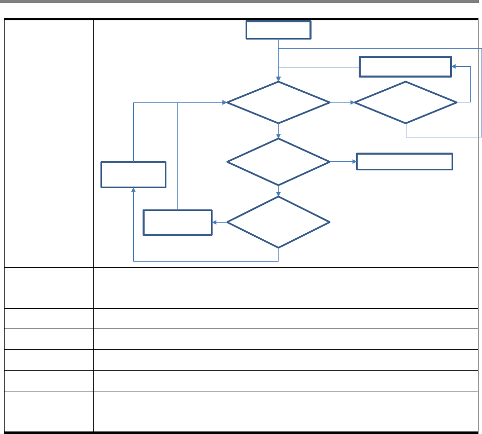
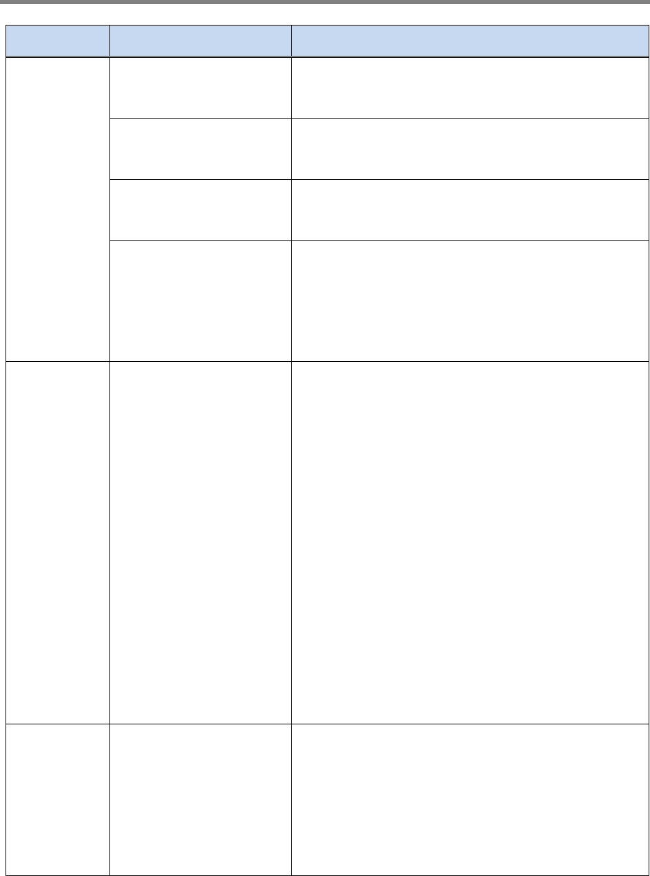
AOC on
Isolation Detect
< Isolation Limit
ALC Attenuation
+5dB
Isolation Detect
< Isolation Limit-4
ALC Attenuation
+1dB
No
Yes
ALC Attenuation
≥30dB Shutdown
Yes
Yes
No
Isolation Detect
>Isolation Limit-3
ALC Attenuation-1dB
Yes
No
No
Repeater User Manual
SmartCell Repeater
25
4. SETUP
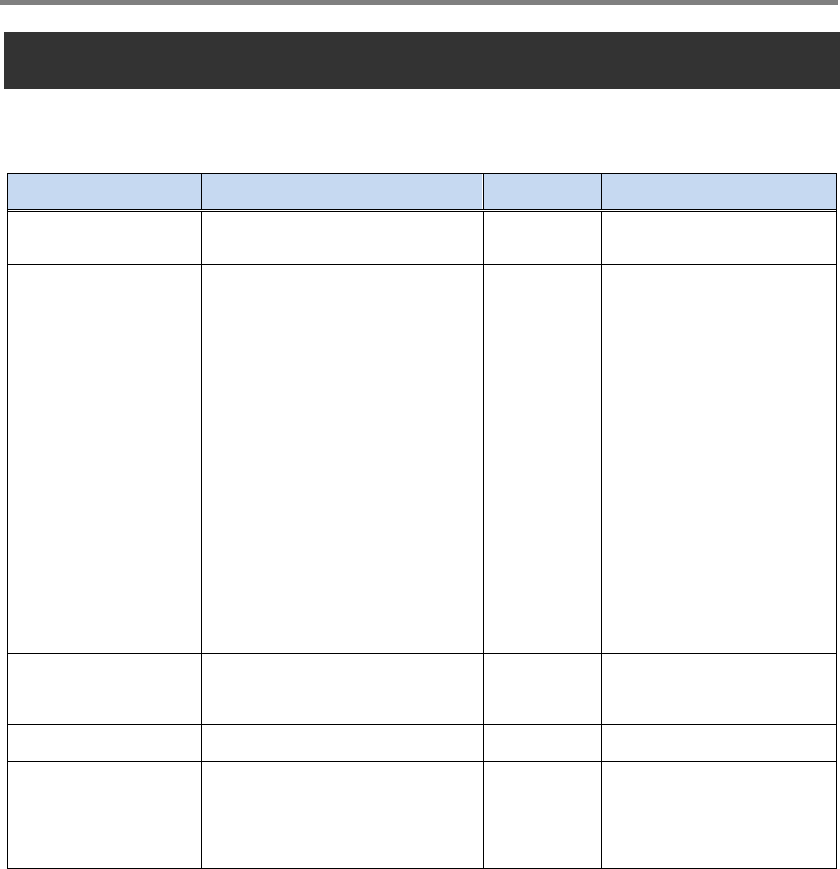
4.1. Equipment Needed for Repeater Setup
Parameter Item Quantity Remark
Major Component Smart-Cell Repeater 1 EA Provided by GST
Additional
Components
WALL Mounting Bracket
CD which contains User Manual
V.1.0 and Installation Guide V.1.0
Ethernet Cable 6.6ft (2m)
Ground Cable 6.6ft (2m)
Ground SEMs Screw M4 x 8mm
Bracket SEMs Screw M6 x
10mm
Lag Screw 12.7mm x 50.8mm
FEU-AMP unit cable
FEU-Wall Bracket cable
1 EA
1 EA
1 EA
1 EA
4 EA
4 EA
4 EA
8 EA
2 EA
Provided by GST
Antenna Donor ANT
Service ANT
1 EA
1 EA Not Included
RF Cable Antenna connection Cable TBD Not Included
Testing and
Measuring
Equipment
Spectrum Analyzer 1 EA Not Included
4.1.1. Check points before turning on the Repeater
1) System Power Check
① AC electrical power to the repeater should be 110V, input electricity only after
power verification.
2) Input RF Signal Range
① Optimal input RSSI into the repeater is -57dBm ~ -27dBm for
700MHz/850MHz/1900MHz/2100MHz/2500MHz/2600MHz. User should verify

Repeater User Manual
SmartCell Repeater
26
input condition of Donor ANT. If the input RSSI exceeds -27dBm, impose the
using external attenuators should be used.
3) Isolation check between DONOR/SERVEICE ANT
① Isolation condition of this equipment is 105dBc (Gain+15dB). User should check
its condition before installation.
4.1.2. Open for Service
1) Check points before open:
① Verification of system installation status :
Electricity, In/Out antennas, cable connection, and equipment mount status.
② Verification of system accessories :
User should check all necessary accessories.
③ Check receipt signal level :
Installer should check whether environmental conditions are in accordance
with system specification to ensure that system operation will be optimized.
2) Check points after open:
① Check external LED
RUN: Green light ON (Off: all lights off)
ALARM: Green light in normal status, Red light in alarming
SHUT DOWN: Green light in normal status, Red light in Shutdown status
Repeater User Manual
SmartCell Repeater
27
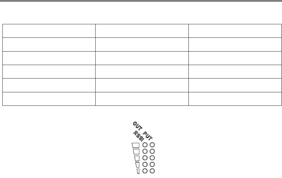
4.1.3. Signal Strength LED Check
Number of LED bars Input Signal Level Output Power Signal Level
LED 1 bar Less than -86dBm Less than +5dBm
LED 2 bars -85dBm ~ -79dBm +6dBm ~ +10dBm
LED 3 bars -78dBm ~ -72dBm +11dBm ~ +15dBm
LED 4 bars -71dBm ~ -65dBm +16dBm ~ +20dBm
LED 5 bars More than -64dBm More than +21dBm
<Figure 9> Modular Repeater Front LED

Repeater User Manual
SmartCell Repeater
28
4.2. Setting up the Repeater
4.2.1. Quick GUI/Configuration
Use the following steps to commission the Repeater after all the cabling and antennas
are fixed in place and the Repeater is supplied with proper electrical power. The repeater
will need a good quality stable Downlink RSSI input level in the range of -85dBm to -
60dBm.
1) Connect your laptop to the repeater with a Crossover Ethernet cable.
2) Verify that your laptop has all wireless connections off and is Obtaining an IP address
automatically, or is using a proper fixed IP address such as: Use the following IP address:
172.16.6.81 with a Subnet Mask of 255.255.255.252.
3) Open Internet Explorer and go to: 172.16.6.81
4) User name: admin
5) Password: admin
4.2.2. Quick Setup
1) Go to the RF Configuration page.
2) Before the Amplifier (HPA) can be turned on, set the Uplink and Downlink attenuation
(ATT) to the maximum value and click Apply.
3) Select the correct Band Block and set the ALC Downlink and Uplink Limits to the
desired level and click Apply. (To adjust the Output Power, change the ALC Downlink
and Uplink Limits to the desired levels).
4) To check the Repeater’s status, click on the Status page.
5) To change the Repeater’s gain/attenuation, adjust the Uplink and Downlink
attenuation in equal amounts not more than 5dB at a time and click Apply.
Repeater User Manual
SmartCell Repeater
29
4.3. Web UI Ranges Table
GUI Feature Range Description
Downlink and Uplink Output
Power Display
Below 0dBm to
35dBm The output Power of the Repeater
Downlink Low RF Power 2dB to 10dB Threshold for Low RF Power
Downlink and Uplink
Attenuation Control 0dB to 30dB Reduces Gain Internally
Downlink and Uplink ALC
Limit 0dBm to 33dBm Limits Output Power
Downlink RSSI Display -100dBm to -27dBm Downlink Receive Level at Donor
Antenna Port
Downlink Low RSSI -93dBm to -57dBm Threshold for Low RSSI
Downlink and Uplink AMP
Control On/Off High Powered Amplifier
Gain Balance Control On/Off Equalizes Uplink and Downlink Gain
Gain Balance Value 0dB to 15dB Subtract Uplink Gain by G/B Value
Shutdown Control On/Off Shutdown if Major Alarm is Reported
Auto Gain Setting On/Off Automatic Gain Setting for the
Repeater
Auto Oscillation Check On/Off Preventing Oscillation
Temperature Display 32 to 260.6 Degrees Internal Repeater Temperature
AMP Temperature Upper
Limit 0 to 299 Degrees Threshold for Temperature Alarm
Band Blocks Used/Bandwidth Each AMP The Channel the Repeater will be
using
Delay Alarm Report 0 or 5 Minutes Time Delay of Reporting after Alarm
is Detected

Repeater User Manual
SmartCell Repeater
30
4.4. Troubleshooting
In case of abnormal operation, technician should diagnose abnormality via remote access
or directly connecting to repeater using Ethernet cable. If technician is required to conduct
repairs due to major alarm, repeater should first be powered off, and then technician
should prepare the proper measurement equipment before trying to fix the problem. In
most cases of major repairs, GST will simply replace the unit and conduct repairs at the
appropriate facility.
4.4.1. Simple Troubleshooting Method
1) Verify LED Status, both on external LED’s as well as internal module LED’s
- Normal operation: Green light on. Alarming: Red LED on.
2) Technician should check external and internal connectors to ensure that all
connections are tightly secure. These connectors should be cleaned regularly.
3) If technician thinks there is a serious problem, call after sales team for over-the-phone
technical support. 1-866-9-GST-USA (1-866-947-8872)
4.4.2. Alarm Information
Alarm
Name
What causes this
alarm Troubleshooting Methods
Downlink
Spurious
emissions
out of spec
Downlink Output
Power exceeds
Downlink Upper Limit
* The Downlink Output Power should not exceed the
maximum composite power spec for this unit.
* If the Downlink Output Power is not exceeding the
composite power spec for this unit, try to increase the
Downlink Upper Limit on the RF Configuration Page.
* Add equal amounts of Uplink and Downlink
attenuation until the Downlink Output Power is less
than the Downlink Upper Limit.
* Set the ALC Downlink Limit on the RF Configuration
Page to a value lower than the Downlink Upper Limit
Downlink Downlink path gain is * By default, if the Downlink Low Output Variance is

Repeater User Manual
SmartCell Repeater
31
Hardware
failure
6dB less than RSSI
plus Output Power
set to 10dB, the Repeater will not report this alarm.
* Increase the Downlink Low Output Variance
on the
RF Configuration Page.
Downlink
Donor power
too low
Input RSSI from
Donor site is 8dB less
than Downlink Low
Input Limit
* By default, if the RSSI Lower Limit is set to -93dBm,
the Repeater will not report this alarm.
* Decrease the Downlink Low RSSI Limit level on the
RF Configuration Page.
* Increase the RSSI level into the Repeater.
Downlink
VSWR
When the VSWR
Ratio on the Server
Port is greater than
3 : 1
* "Sweep the line" to check for loose or damaged
connectors and/or cabling.
* If after checking the entire Server side, the VSWR
alarm still exists and the system is working fine, Disable
the alarm on the Alarm Configuration page.
Downlink
Donor power
too high
Downlink Input
Power exceeds -
25dBm
* Check the direction of donor antenna
* Even if higher input power after the modifying
direction of donor antenna, Be adding an attenuator
at the Donor port.
Downlink
Synthesizer
failure
Synthesizer (in
Downlink path) has
occur Failure
* By using a switch on the back of the repeater, resets
the power
* Call to GST’
s Tech Support Team and exchange the
AMP unit.
Downlink
Interfere
power
exceeded
If an external signal is
higher than the in
band signal, more
than 15dB signal
* Call the GST’s Tech Team , resolved in accordance with
the procedure.
Uplink Out
of band
emissions
out of spec
Uplink Output Power
exceeds Uplink Upper
Limit
* The Uplink Output Power should not exceed the
maximum composite power spec for this unit.
* If the Uplink Output Power is not exceeding the
composite power spec for this unit, try to increase the
Uplink Upper Limit on the RF Configuration Page.

Repeater User Manual
SmartCell Repeater
32
* Add equal amounts of Uplink and Downlink
attenuation until the Uplink Output Power is less than
the Uplink Upper Limit.
* Set the ALC Uplink Limit on the RF Configuration
Page to a value lower than the Uplink Upper Limit
Uplink Power
at coverage
port too
high
Uplink Input Power is
higher than -25dBm
* Check the direction of Coverage antenna
* When another device is connected to the Coverage
port as DAS System
1) Add an attenuator on Coverage port, or
2)
Uplink to adjust the output of the additional
equipment.
Uplink
Synthesizer
failure
(Uplink
Hardware
failure)
Synthesizer (in uplink
path) has occur
Failure
* By using a switch on the back of the repeater, resets
the power
* Call to GST’
s Tech Support Team and exchange the
AMP unit.
Uplink
(Downlink)
Software
failure
When an alarm
occurs in DFM's at
the AMP unit.
* By using a switch on the back of the repeater, resets
the power
* Call to GST’s Tech Support
Team and exchange the
AMP unit.
Oscillation
detected/Lo
w isolation
Insufficient isolation
is detected when the
Repeater is at
minimum gain
* Verify that the Donor antenna is on the same side of
the building as the Donor site, and if needed, raise the
Donor antenna up on a pole.
* Change the types of antennas used, such as Yagi to
Corner-
Reflector for outdoors, and Omni to a Panel for
indoor use.
* Move the closest indoor service antenna farther away
from the outside Donor antenna.
* Close the repeater door if opened and verify that the

Repeater User Manual
SmartCell Repeater
33
closest indoor coverage antenna is not in the same
room as the repeater.
Field
Replaceable
module
failure
Filter service has not
matches between
Amp Unit and DFM
* Call to GST's Tech Support Team to verify that all the
settings are correct.
Tamper
Detected
When mount
information (in the
system ) is changed
* After 5 minutes clear automatically.
* If you want to disable, you can on the Alarm
Configuration page.
Communicat
ion Failure
If the communication
between the NMS
Board and Amp Unit
would not operating
normally
* SNMP board or AMP unit need to reset.
* Open the rear cover and check the each cable.
Power
Supply out
of range
The internal Power
Supply detects
improper Voltage
* If the system is working fine, disable t
he alarm on
the Alarm Configuration page.
* Call to GST's Tech Support Team to verify that all the
settings are correct.
Over
Temperature
Internal AMP
temperature exceeds
the Temperature
Limit
* Verify that the Temperature Limit is set between
176 °F ~ 201 °F on the RF Configuration page. (Default
Value is 163°F)
Reset alarm When the unit has
reset * After 30 seconds clear automatically.
Manual
Shutdown
When the operates
shutdown algorithm,
after re-check
* By using a switch on the back of the repeater, resets
the power
* Reset the AMP unit, By Web UI.
FAN in the event of a fan
failure * Replace the fan
4.4.3. Troubleshooting Guide Related to RF
Repeater User Manual
SmartCell Repeater
34
Item Check Point Troubleshooting
Check
before
system
operation
System input power
range
-Downlink: -100dBm ~ -27dBm
-Uplink: -100dBm ~ -27dBm
System gain
(DL/UL) - 60dB ~ 90dB
Output power
at server port
- Downlink: 33dBm ± 2dB
- Uplink: 33dBm ± 2dB
Check points before
open for service
-
Please check quantity of all accessories with
specification before you set up
-
Fit cable length in accordance with field
condition
Check after
system
operation
Check points after open
for service
Check following status;
-
Verify that the antennas are securely mounted
and pointed in the correct directions
-
Connection status between antennas and RF
cable
-Verify that the Repeater is securely mounted
-Proper AC power status
-Grounding status of electrical circuit
-Coaxial cable (RF) construction status
-Connectors and combiners connection status
-Cable connec
tion status against leakage of
water
When
repeater
does not
work
properly
Check electricity cord
connection status -Re-plug in Adapter cord

Repeater User Manual
SmartCell Repeater
35
When in
alarming
DL VSWR alarm
Please Check following status;
-Make sure Server Antenna Port is disconnected.
-
Please reset Adapter upon completing Alarm
troubleshooting
DL over-output alarm
-Make sure output power is operating normally
-
Please Reset Adapter upon completing Alarm
troubleshooting
UL over-output alarm
-Please make
sure output level is operating
normally
-
Please reset Adapter upon completing Alarm
troubleshooting
Temperature alarm
Check following status;
-Setting level of maximum temperature limit
-Temperature offset is normal or not
-Circumstances of temperature
-
Please Reset Adapter upon completing Alarm
troubleshooting
RF off
-Verify that the HPA’s are On
-
Please Reset Adapter upon completing Alarm
troubleshooting
When
output
power is no
longer
problem
Technician should verify
category of alarm at
the front side of
repeater
-When Red light on the Shutdown LED, technician
should troubleshoot the alarm via Notebook
computer
-Technician should
connect antenna with
output port of repeater
-Please make sure all
connectors are fastened
-Reconnect the connector
-Change it if the connector is defective

Repeater User Manual
SmartCell Repeater
36
Check the input level -Increase output power or check input change of
BTS side
Check gain of the unit -If the Gain is different from normal level, please
contact A/S team
Cable connector loose
-It is possible for connectors to get too tight and
damage the equipment or throughput
-Please contact installer or service provider upon
verification
In case of
dropped call
or bad
signal after
set up
Check input signal
strength in the service
area
-
Increase output power level of repeater by
adjusting attenuation level
If input signal strength
is not a problem,
please check delay of
calling time
-Increase output level of Uplink signal, then set to
optimal level.
Check RSSI signal
strength
-
Contact network management team or service
provider
In case
output
Signal
wavelength
is not shown
flat or looks
like
oscillation
Check connection
fastened between
antenna and cable
(Signal wavelength
should be flat and
stable if technicians
shake CABLE. If not, it is
connection problem)
-
If connection is not proper, reconnect cable and
connector and then check the output power again
Input level change or
module overheating
-Check input level from BTS side.
-Check performance of each module (Diagnosed
by A/S team)
Please check VSWR of
the cable is normal -Change to normal Cable

Repeater User Manual
SmartCell Repeater
37
Repeater User Manual
SmartCell Repeater
38
4.4.4. Troubleshooting Guide Related to NMS
Symptom Check Points Troubleshooting
Link Fail
Communication
problem
-
In case of Ethernet, verify IP addressing, DHCP
function, and that cookies are deleted
-
Verify that a crossover Ethernet cable is being
used
CLI connection, cable
status check
-Make sure 1:1 connection
-
Follow instructions in the installation guide for
this connection procedure
CLI connection Check
by USB to serial cable
-Please verify port number of PC communication
-Please check cable connection status
If technician thinks there is a serious problem, call after sales team for over-the-phone
Technical support. 1-866-9-GST-USA (1-866-947-8872).
6900 College Blvd. Suite 850
Overland Park, Kansas 66211 Tel: 913 469 6699
Fax: 913 661 0163 Email: support@gsteletechinc.com
Web: http//www.gsteletechinic.com
6900 College Blvd. Suite 850
Overland Park, Kansas 66211 Tel: 913 469 6699
Fax: 913 661 0163 Email: support@gsteletechinc.com
Web: http//www.gsteletechinic.com