GSI ELECTRONICS EDGERFID Remote Module with RFID function User Manual KP 8IN 1REL TP 8IN 1REL TR 2IN 1REL
GSI ELECTRONICS INC. Remote Module with RFID function KP 8IN 1REL TP 8IN 1REL TR 2IN 1REL
User Manual
KP-8IN-1REL, TP-8IN-1REL, TR-
2IN-1REL
Models:
890-00607
Installation manual
895-00695
Version 00
Date: 02-01-16
895-00695

2 895-00695

Contents
Chapter 1 Introduction...............................................................................................................................5
Contact information .....................................................................................................................5
General safety precautions and usage ..........................................................................................5
Terms of use ...............................................................................................................................7
What to look for when you receive your system..............................................................................8
System overview.........................................................................................................................9
Operating environment ..............................................................................................................12
Clearance around the KP-8IN-1REL, TP-8IN-1REL, TR-2IN-1REL ...............................................13
Correctly supporting and routing cables ......................................................................................13
Grounding recommendations for the system ...............................................................................14
Chapter 2 Basic connections...................................................................................................................17
Preparing the enclosures for installation......................................................................................17
Mounting the enclosures............................................................................................................17
DC network or independent power supply connection ..................................................................18
Connecting the the KP-8IN-1REL, TP-8IN-1REL, TR-2IN-1REL to the communication
network ........................................................................................................................19
Connecting an analog input........................................................................................................20
Connecting the relay output .......................................................................................................21
Grounding ................................................................................................................................22
Chapter 3 Maintenance............................................................................................................................23
Inspecting and cleaning the enclosure ........................................................................................23
Inspecting and tightening connections ........................................................................................23
Chapter 4 Troubleshooting......................................................................................................................25
Appendix A Navigating through the KP-8IN-1REL ......................................................................................27
Appendix B LED meaning...........................................................................................................................29
Appendix C List of terminals ......................................................................................................................31
Appendix D Technical Specifications .........................................................................................................33
Appendix E Safety Characteristics and Certification ..................................................................................37
Appendix F EC Declaration of Conformity (In accordance with EN ISO 17050-1 2004)................................41
Appendix G FCC part 15 statement.............................................................................................................45
Appendix H FCC RF exposure statement....................................................................................................47
Appendix I Innovation, Science and Economic Development Canada ICES-003 Compliance CAN
ICES-3 (A)/NMB-3(A)..........................................................................................................49
Appendix J FDA declaration.......................................................................................................................51
Appendix K Reduction of Hazardous Substances ......................................................................................53
Appendix L Disposal and Recycling Information........................................................................................55
Appendix M Product material composition .................................................................................................57
Appendix N Packaging characteristics.......................................................................................................59
Appendix O Low voltage cable specifications ............................................................................................61
Appendix P Extending a cable....................................................................................................................63
Appendix Q KP-8IN-1REL, TP-8IN-1REL, TR-2IN-1REL - Product End-of-Life Disassembly
Instructions.......................................................................................................................65
GSI Group, LLC Limited Warranty ...........................................................................................69
895-00695 3

NOTES
4 895-00695
1Introduction
Topics Covered in this Chapter
▪ Contact information
▪ General safety precautions and usage
▪ Terms of use
▪ What to look for when you receive your system
▪ System overview
▪ Operating environment
▪ Clearance around the KP-8IN-1REL, TP-8IN-1REL, TR-2IN-1REL
▪ Correctly supporting and routing cables
▪ Grounding recommendations for the system
Contact information
Manufacturer
GSI Electronics
5200 Armand Frappier
Saint-Hubert, Qc
Canada
J3Z 1G5
WARNING
Warranty is void if this product is used in a manner not specified by the
manufacturer. Every effort has been made to ensure that this manual is complete,
accurate and up to date. The information contained in this manual is subject to
change without notice.
General safety precautions and usage
Safety symbols
Warning. Read the following text carefully; it contains important information
which, if ignored, may cause the controller to operate improperly
High Voltage. Hazard of electrical shock. Read the message and follow the
instructions carefully
Direct current (DC)
Alternating current (AC)
895-00695 5
Chapter 1: Introduction
Protective Earth Ground Terminal, Primarily used for protective earth
terminals.
Terminal connected to conductive parts of a device for the purpose of safety
and is intended to be connected to an external system for protective
grounding
Functional Ground Terminal Primarily used for functional earth terminals
which are generally associated with test and measurement circuits. These
terminals are not for safety earthing purposes but provide an earth reference
point.
NOTE: To emphasize points or remind readers of something, or to indicate minor
problems in the outcome of what they are doing
CAUTION
Failure to follow the instructions can result in damaged equipment or loss of
data or potential problems
DANGER
Failure to follow the instructions carefully can result in serious or fatal injury
IMPORTANT: The following information is of great significance and must be read carefully
WARNING
Read the following text carefully; it contains important information which, if
ignored, may cause the controller to operate improperly
Tip Shortcut or a faster way of getting to an end result
Safety messages
DANGER
Turn off the main electrical disconnect switch prior to servicing any of the boxes.
Failure to do so might lead to serious injury or death.
Always use extreme caution when measuring voltage or performing procedures that require a
module to be powered on.
Electrostatic discharge prevention when manipulating a printed circuit board
(PCB)
Electrostatic discharge (ESD) can damage equipment and impair electrical circuitry. ESD damage occurs
when electronic components are improperly handled and can result in complete or intermittent failures.
Always follow ESD on a PCB-prevention procedures when you remove and replace components. Ensure
that the chassis is electrically connected to earth ground. Wear an ESD-preventive wrist strap, ensuring
that it makes good skin contact. Connect the grounding clip to an unpainted surface of the chassis frame
to safely ground unwanted ESD voltages. To guard against ESD damage and shocks, the wrist strap and
cord must operate properly. If no wrist strap is available, ground yourself by touching the metal part of the
chassis.
6 895-00695
Chapter 1: Introduction
For safety, periodically check the resistance value of the antistatic strap, which should be between 1 and
10 megohm (Mohm).
Telecommunication advice
FCC Caution and Safety Notices:
Any changes or modifications (including the antennas) made to this device that are not expressly
approved by the manufacturer may void the user’s authority to operate the equipment. This device and its
antenna(s) must not be co-located or operating in conjunction with any other antenna or transmitter.
FCC ID and IC ID
Health and radiation
This equipment should be installed and operated with minimum distance 20 cm between the radiator and
your body. Equipment type and class type of the RFID module according to (ETSI EN 301 489-3)
Equipment type (ETSI EN 301 489-
3)
III Others : Identification/Access
control
Class type (ETSI EN 301 489-3) 2(Medium reliable SRD communica-
tion media; e.g. causing inconven-
ience to persons, which cannot
simply be overcome by other
means)
Terms of use
Read and follow all installation, operation, and maintenance information carefully before using the prod-
uct. Refer to the user documentation for complete product specifications. If the product is used in a
manner not specified, the protection provided by the product warranty will be void.
Using the product according to your function
A responsible body is an individual or group responsible for the use and maintenance of equipment, for
ensuring that the equipment is operated within its specifications and operating limits, and for ensuring
that operators are adequately trained.
Operators use the product for its intended function.
Maintenance personnel perform routine procedures on the product to keep it operating properly
Service personnel are trained to work on live circuits, perform safe installations, and repair products. Only
properly trained service personnel may perform installation and service procedures.
General safety usage
Follow the guidelines given below for safe usage of the product:
• Installation must only be performed by qualified service personnel
• Carefully read all instructions
• Comply with local and national safety codes
• Repairs must only be performed by qualified service personnel
• When replacing the fuses, use only the same type and same rating as specified
895-00695 7
Chapter 1: Introduction
• Make sure the unit is disconnected from AC Power when servicing
• Do not try to operate the system if it is damaged. Disconnect the Power from the units and call your
local service representative
• Do not operate while condensation is present
• Use of the system in a manner not specified by these instructions may impair the safety protection
provided by the system. Do not operate the system outside its rated supply voltages or environmen-
tal range
• Omission to read the installation and user manuals or to comply with the warnings and references
contained herein can result in serious bodily injury or damages to the controllers
• Do not insert metal objects into the connectors
• Use the system only as specified, or the protection supplied by the product can be compromised
• Follow all installation and maintenance recommendations and consider all provided information
regarding product specifications and limitations
• Do not use the system if it does not operate correctly
• The enclosures must be closed and locked at all times, particularly when operating the system
• Use only specified replacement parts
What to look for when you receive your system
Table 1-1 Shipment contents
KP-8IN-1REL 1 X KP-8IN-1REL 1 X Quick guide
TP-8IN-1REL 1 X TP-8IN-1REL 1 X Quick guide
TR-2IN-1REL 1 X TR-2IN-1REL 1 X Quick guide
Damage inspection
Your system and its components were carefully inspected both electrically and mechanically before ship-
ment. After unpacking all items, check for any obvious signs of physical damage that may have occurred
during transit. Report any damage to the shipping agent immediately. Save the original box for possible
future shipment.
Returning the unit for repair
If you must return the system for repair, carefully package the system in its original box or an equivalent,
and follow these instructions:
1. Call the customer service department to get a Return Material Authorization (RMA) number. Have
on hand the system’s serial number and date code found on the system’s main board.
2. Indicate clearly that the box is to be given to the repair department and attach a copy of the RMA
number on the shipping label.
Contact information
If you experience trouble with your system, or to get repair or warranty information, please contact
GSI Electronics Inc.
Phone: 1-877-926-2777
8 895-00695
Chapter 1: Introduction
E-mail: mtl_techsupport@gsiag.com.
System overview
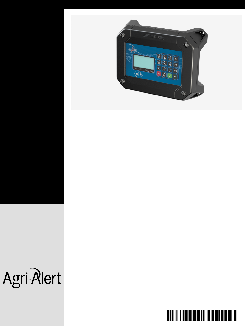
These external modules can be used with the Agri Alert 128 Touch system network.
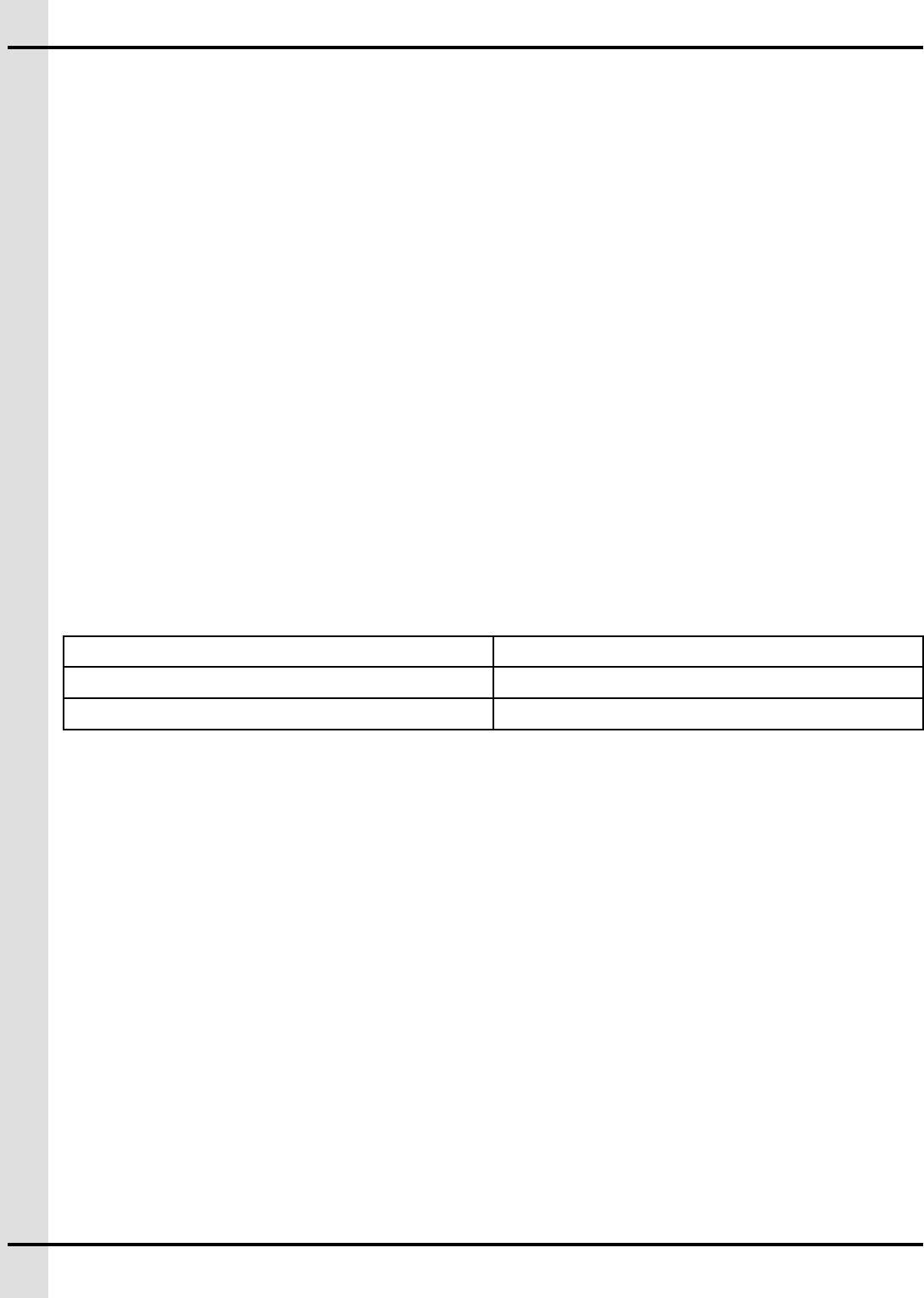
KP-8IN-1REL — Remote keypad displaying data from the main system that allows the addition of 8 sen-
sors inputs and a programmable relay output
Figure 1-1 KP-8IN-1REL
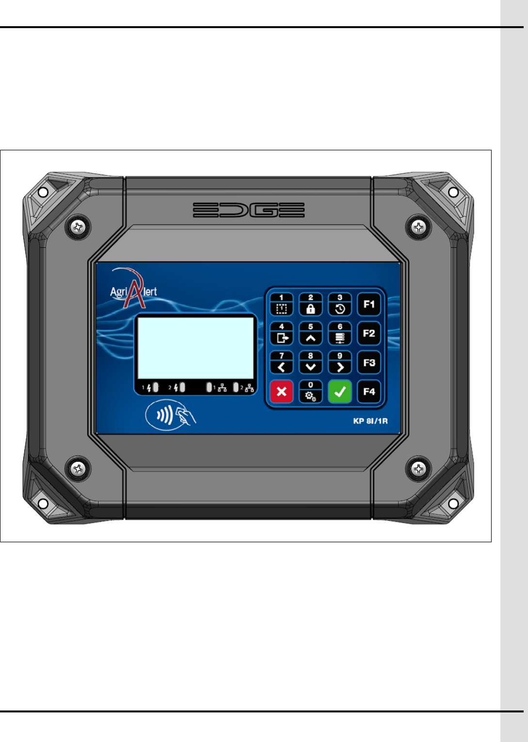
TP-8IN-1REL — Remote expansion module that allows the addition of 8 sensors inputs and a program-
mable relay output
895-00695 9
Chapter 1: Introduction
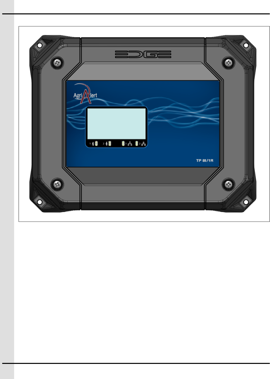
Figure 1-3 TR-2IN-1REL
The KP-8IN-1REL and TR-2IN-1REL modules are equipped with an RFID tag reader. This means that
every time a tag is scanned, is keeps track of the scan and sends information to the Main Controller. In
addition, when you activate the output through a scan, the relay is energized for the predetermined period
of time. Even if the module is disconnected from the Main Controller, it will be able to scan, record and
activate the output. To ensure compatibility with system, use the tags provided with the module.
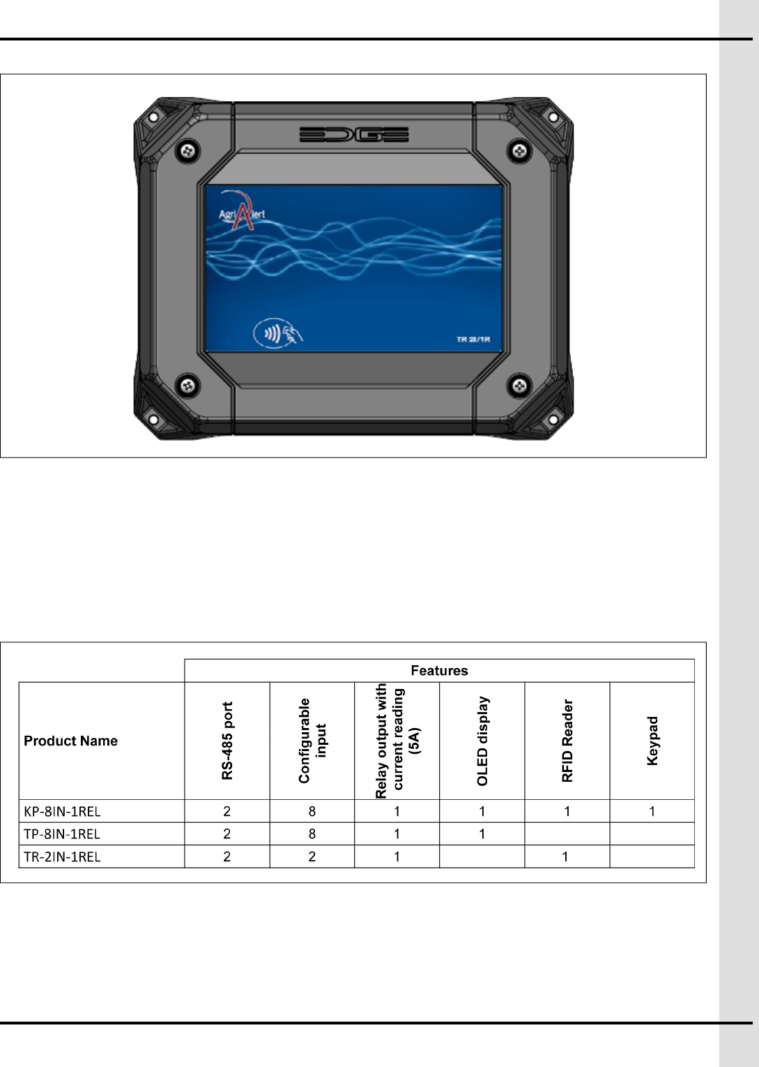
The hardware features according to the model are as follows:
895-00695 11
Chapter 1: Introduction
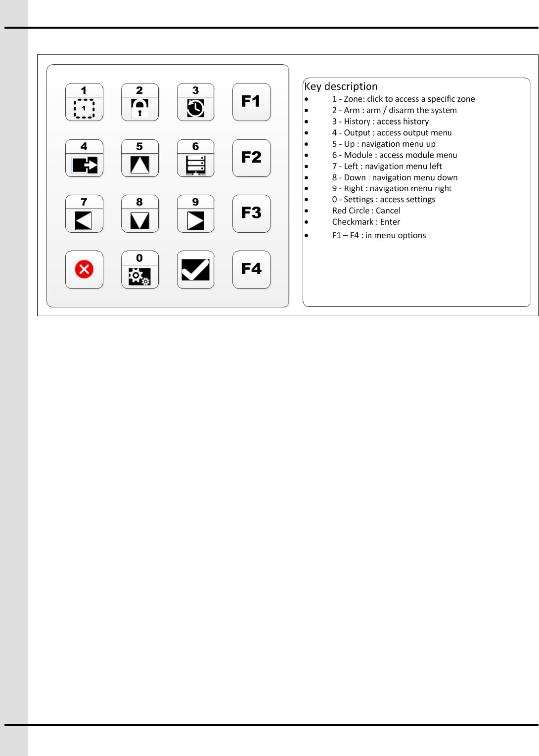
KP-8IN-1REL menus and navigation
For complete navigation instructions, see Appendix ANavigating through the KP-8IN-1REL, page 27
Operating environment
Inside use
To avoid exposing the system to harmful gases or excessive humidity, install the KP-8IN-1REL, TP-8IN-
1REL, TR-2IN-1REL in a corridor or a room dedicated to electronic controllers. The ideal ambient temper-
ature is between 20 °C and 25 °C (68 °F - 77 °F). The temperature should not be below 0 °C (32 °F) and
should not exceed 40 °C (104 °F).
Ensure there is sufficient ventilation around the unit.
Install the KP-8IN-1REL, TP-8IN-1REL, TR-2IN-1REL far from sources of vibrations and where they are
not likely to get bumped.
Outside use
Install the KP-8IN-1REL, TP-8IN-1REL, TR-2IN-1REL far from sources of vibrations and where they are
not likely to get bumped.
Install the KP-8IN-1REL, TP-8IN-1REL, TR-2IN-1REL in an easily accessible area.
IMPORTANT: If you are not planning on installing the system immediately, store it in a cool dry place.
Requirements for the mounting structure
Fix the enclosure into the supporting structure behind the drywall. If this is not possible, consider the addi-
tion of a wood frame on which the enclosure could be screwed.
12 895-00695
Chapter 1: Introduction
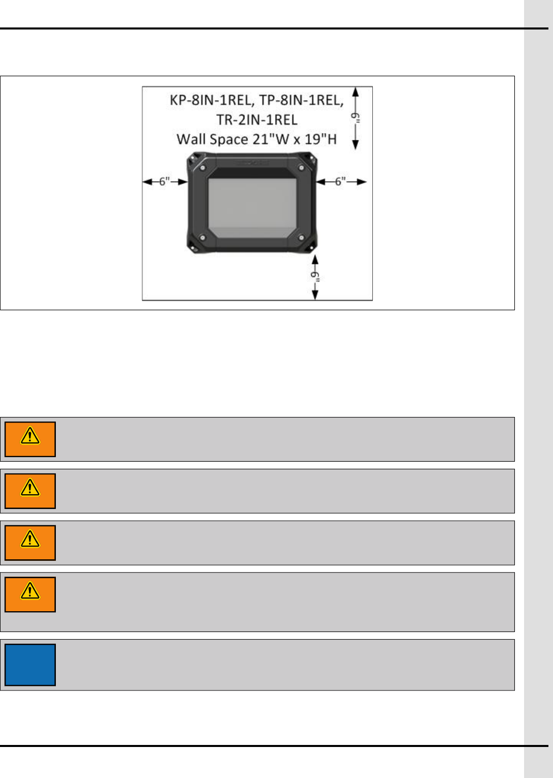
Clearance around the KP-8IN-1REL, TP-8IN-1REL, TR-2IN-1REL
Figure 1-4 Minimum clearance
Correctly supporting and routing cables
Properly supporting and routing the cables helps avoid electromagnetic interference and wire damage.
Rigid conduits of up to 1 inch (25.4mm) can be used for connection to the P-8IN-1REL, TP-8IN-1REL,
TR-2IN-1REL.
NOTE: Nylon cable glands are permitted for cable or wire fastening.
WARNING
Use watertight compression cable glands rated IP66 for each cable used.
WARNING
Use silicone to seal the cable gland rated IP66 if more than one cable is used in the
same cable gland.
WARNING
The warranty is void if the product enclosures are not sealed correctly and the
installation does not respect the manufacturer recommendations.
WARNING
Ensure all cables enter through the bottom of the plastic enclosure. Do not make
holes on the top or on the sides of the enclosures. Be careful not to damage the
electronic cards located inside the enclosure when drilling at the bottom of the
enclosure.
NOTICE
The use of flexible tube with water and dust tight connectors at both ends is
acceptable.
Cable support
Support the cables with clips or cable trays whenever possible to avoid damage at the connection points.
895-00695 13
Chapter 1: Introduction
Cable routing
NOTICE
Never run low voltage (24V and less) wires like communication wires, inputs or
sensor wires in the same conduit as a high voltage (Power) wires.
When low voltage cables run parallel to high voltage cables (120/230/380 VAC or 24 VDC), place them at
a distance of at least 300 mm (12 inches) from each other to avoid electromagnetic interference.
If low voltage cables cross high voltage cables, ensure they cross at a 90° angle to minimize electromag-
netic interference.
WARNING
Do not use rigid conduits over 1 inch (25.4mm) for the KP-8IN-1REL, TP-8IN-1REL,
TR-2IN-1REL.
Grounding recommendations for the system
A correctly grounded system protects your equipment from electrical surges and spikes.
CAUTION
Each module must have its own ground connection from a common junction box.
Do not run the earth ground cable between the modules.
NOTICE
The ground resistance levels must comply with local and national electrical codes.
IMPORTANT: If outdoor connections are used, mount the enclosure as close as possible to the entry
point of the outdoor wiring.
IMPORTANT: An improper ground connection voids the system’s warranty.
Insert the rod into the ground until a few inches of the tip is left above ground level. Attach the cable to the
rod tip with an appropriate connector. Attach the other end of the cable to a breaker box or a junction box
near the main enclosure.
14 895-00695
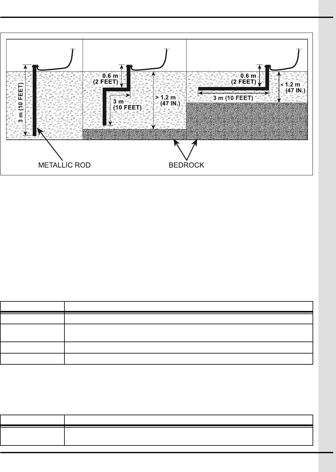
Chapter 1: Introduction
Figure 1-5 Grounding installation depending on bedrock depth
• If the bedrock is more than 3 meters (10 feet) below ground level, drive the grounding rod vertically
3 meters (10 feet) into the ground.
• If the bedrock is more than 1.2 meters (47 inches) below ground level, drive the rod into the ground
to bedrock level and bury the remainder horizontally at least 0.6 meters (2 feet) below ground level.
• If the bedrock is less than 1.2 meters (47 inches) deep, bury the rod horizontally at least 0.6 meters
(2 feet) below ground level.
NOTE: Refer to your local regulations and practices if an adequate grounding installation isn’t possible.
Rod specifications for grounding
The rod specifications are guidelines only. Refer to your national and local regulations for compliance
criteria.
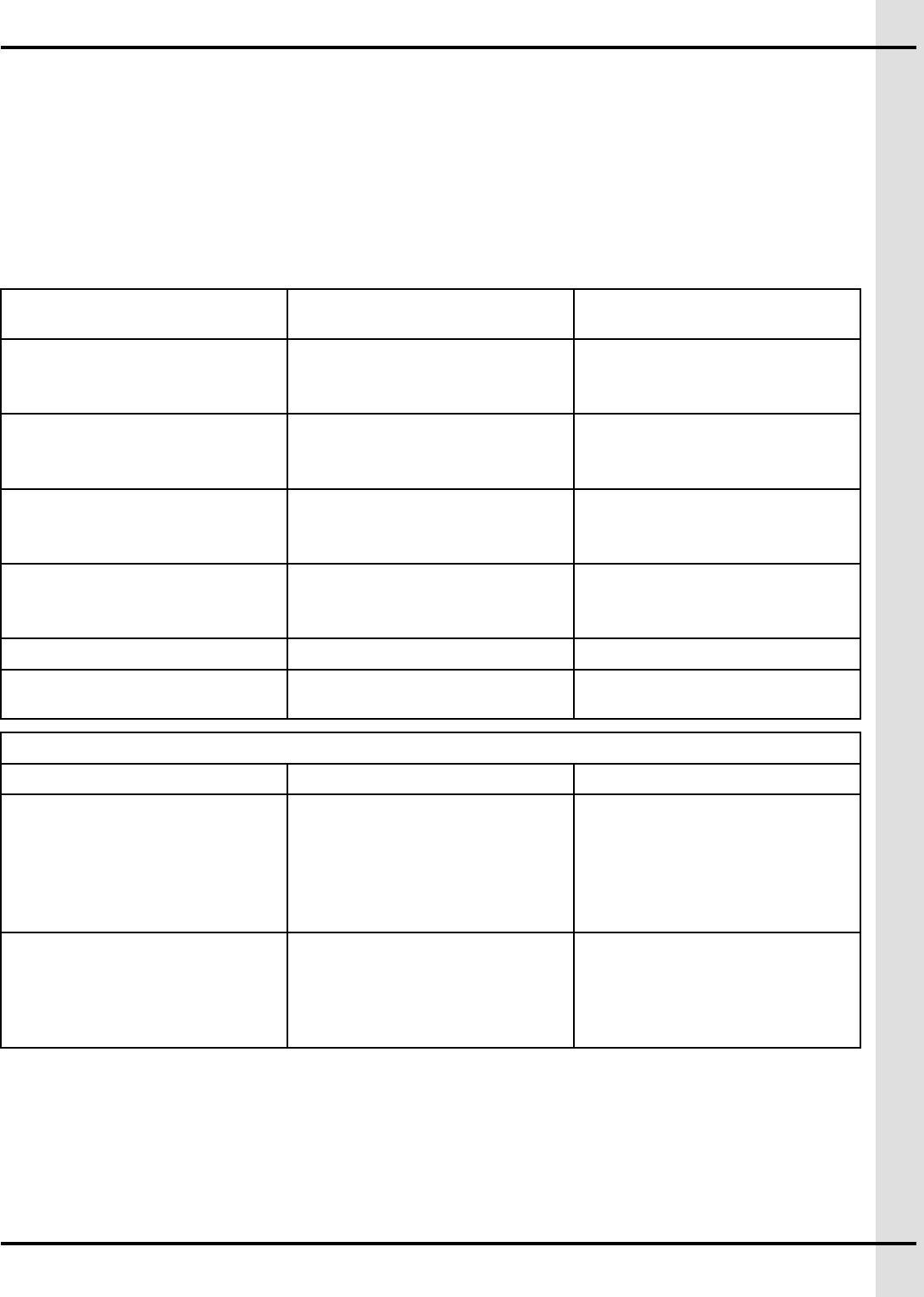
Table 1-2 Grounding rod specifications
Item Description
Material Metallic, normally steel core.
Rod surface The surface must be clean. It cannot be coated with paint, varnish or any non-conducting
substance.
Minimum diameter 16 mm (5/8 inches)
Minimum length 2440 mm (8 feet)
Cable specifications for grounding
The cable specifications are guidelines only. Refer to your national and local regulations for compliance
criteria.
Table 1-3 Grounding cable specifications
Item Description
Certification and
type
CSA, TEW type.
895-00695 15


2Basic connections
Topics Covered in this Chapter
▪ Preparing the enclosures for installation
▪ Mounting the enclosures
▪ DC network or independent power supply connection
▪ Connecting the the KP-8IN-1REL, TP-8IN-1REL, TR-2IN-1REL to the communication net-
work
▪ Connecting an analog input
▪ Connecting the relay output
▪ Grounding
Preparing the enclosures for installation
Preparing the equipment before mounting it to the wall facilitates manipulation and ensures all parts are
ready to be installed.
Before You Begin
Wires are separated into two groups: low voltage and high voltage in the plastic enclosure and the
conduits.
NOTE: The use of rigid conduits up to 1 inch (25.4 mm) is allowed for the KP-8IN-1REL, TP-8IN-1REL,
TR-2IN-1REL. .
1. With the enclosure closed, drill a hole the size of the your cable connectors or your rigid conduits at
the bottom of the enclosure.
2. Open the enclosure by unscrewing the top, and remove the plastic fragments.
3. Install the cable connectors or rigid conduit adaptors to the bottom of each enclosure.
4. Close the enclosure using the screws.
IMPORTANT: Leave the rated clearance to allow the cover to be removed for maintenance
Remember
Do not mount the enclosures directly onto the drywall. If the supporting structure behind the drywall
cannot support the enclosure, solidify it by adding a wooden or metal frame.
Mounting the enclosures
Securely mounting the enclosures to the wall in the ideal location allows for an optimal use of the system
when using the OLED screen (KP-8IN-1REL, TP-8IN-1REL).
Before You Begin
895-00695 17

Chapter 2: Basic connections
NOTICE
When using outdoor connections, mount the enclosure as close as possible to the
entry point of the wiring
IMPORTANT: The enclosures must be mounted near an AC Power with a disconnecting switch
IMPORTANT: Mount the system into a wooden or metal frame. Do not mount the system directly into the
drywall
NOTE: Install the enclosures (KP-8IN-1REL, TP-8IN-1REL) with the widest side of the screen placed hor-
izontally. Consult the wiring diagram concerning wire length restrictions between the enclosures.
NOTE: GSI Electronics recommends this kind of screw: Deck Screw for Wood
1. Place the enclosure at a height at which you can properly see the screen (KP-8IN-1REL, TP-8IN-
1REL).
2. Screw in the top left hand corner screw first.
3. Using a level, make sure the enclosure is straight, and then screw in the second screw on the lower
right hand corner.
4. Screw in the last two screws.
IMPORTANT: Leave a clearance as stated in Clearance around the system to allow the cover to
be removed for maintenance.
DC network or independent power supply connection
Two possible configurations are available: DC network (available on the Agri Alert 128 Touch network) or
the independent power supply. Depending on the DC network chosen, select the right wiring diagram for
the installation.
NOTICE
When tightening small terminal blocks, use a torque between 0.5N*m (4.43lbf*in) and
0.6 N*m (5.2lbf*in) to fasten a wire gauge from 16AWG to 18AWG.
Connecting the DC network
DC network is available from the AA128 Touch network.
The recommended installation is 16 AWG for the power supply wires at a length of 300 meters (1000
feet).
1. Locate the Automation terminal on the KP-8IN-1REL, TP-8IN-1REL, TR-2IN-1REL you want to
connect.
2. Connect the wires (24 or 28V and GND) from the KP-8IN-1REL, TP-8IN-1REL, TR-2IN-1REL. to the
network.
Consult the wiring diagrams to see the maximum cable distance according to the wire gauge.
IMPORTANT: Make sure to connect same identifications together and use the same network from one
side to the other.
IMPORTANT: In the AA128 Touch network, use the Automation network on the KP-8IN-1REL, TP-8IN-
1REL, TR-2IN-1REL.
18 895-00695
Chapter 2: Basic connections
Connecting the independent power supply (PSU 24V 20W)
IMPORTANT: Install a disconnect switch to interrupt power to L1 and N/L2 electric power lines before
connecting the system’s main input on the power supply. It must be in close proximity to
the equipment and within easy reach of the operator. It must be marked as the disconnect-
ing device for the equipment.
WARNING
If the disconnect switch or the circuit breaker is used as a sectioning device, the
device must be correctly identified with which function of the controller opens the
circuit. The Off or Stop and On position must be clearly identified on the sectioning
device.
GSI Electronics recommends using a DPST disconnecting switch in series with a breaker. In the case of
the use of a SPST disconnecting switch, connect the SPST disconnecting switch to cut the hot line with a
neutral circuit case.
CAUTION
Disconnect supply before servicing
1. From the power source, follow the wiring diagram to connect the main voltage supply to the system’s
main inputs on the PSU 24V 20W.
2. Open the disconnecting switch or breaker before wiring.
3. Plug the wires (L1 to L1, L2/N to L2/N, Earth to Earth) from the PSU 24V 20W into a power source
(main voltage supply).
4. Correctly ground the system by using a Functional Earth configuration.
5. From The PSU 24V 20W, connect the “+” in the 24V input and connect the “-” in the GND input on
the KP-8IN-1REL, TP-8IN-1REL, TR-2IN-1REL.
6. Power on the system and make sure it is receiving power from the power source.
NOTE: The working voltage range is between 90 Vac and 264 Vac. The system consumes a Power of 20
W on a PSU 24V 20W and the wires in accordance with local and national safety codes. A mini-
mum voltage rating of 300V and a minimum temperature rating of 90°C is used for the wires.
Connecting the the KP-8IN-1REL, TP-8IN-1REL, TR-2IN-1REL to the
communication network
The communication bus enables communication between the AA128 Touch system and the KP-8IN-
1REL, TP-8IN-1REL, TR-2IN-1REL (terminal A and terminal B on the Automation network).
1. Locate the Automation terminal on the KP-8IN-1REL, TP-8IN-1REL, TR-2IN-1REL you want to
connect.
2. Connect the wires (A and B) from the KP-8IN-1REL, TP-8IN-1REL, TR-2IN-1REL to the network.
IMPORTANT: Make sure to connect same identifications together and use the same network from
one side to the other.
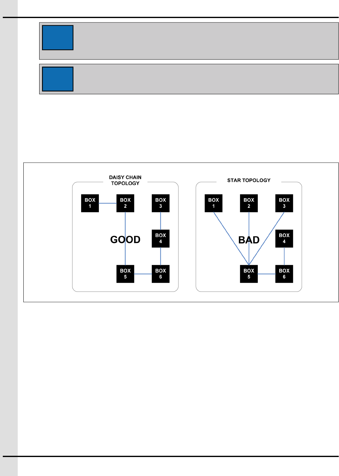
IMPORTANT: The communication network must be installed in a daisy chain topology. Consult the
wiring diagrams to see the maximum cable distance according to the wire gauge.
IMPORTANT: With the Agri Alert 128 Touch network, use the Automation network on the KP-8IN-
1REL, TP-8IN-1REL, TR-2IN-1REL.
895-00695 19
Chapter 2: Basic connections
NOTICE
The recommended installation is 16 AWG for the power supply wires at a length
of 300 meters (1000 feet). The recommended installation is 18 AWG for the
communication wires at a length of 1200 meters (4000 feet). The cable must be
twisted pair and shielded.
NOTICE
When tightening small terminal blocks, use a torque between 0.5N*m
(4.43lbf*in) and 0.6 N*m (5.2lbf*in) to fasten a wire gauge from 16AWG to
18AWG.
The communication network must be installed in a daisy chain topology. The order of the wires is
very important. At both ends of network, the End-of-Line must be activated. If the wiring can’t be
done in a single chain, you might need to deactivate the end-of-line (EOL) resistor to improve com-
munication. GSI Electronics does not warranty the proper operation if the topology network is not
daisy chain.
Connecting an analog input
A variety of different sensors can be hooked up to the system to monitor various inputs. Analog inputs
can be set in 0-5V mode, in dry contact mode, in 4-20mA mode, and in temperature mode. Some exam-
ples of sensors that you can use with the system: temperature probes, humidity probes, static pressure
probes, water meters, dry contacts.
What You Should Know
NOTE: A minimum wire gage of 18 AWG (1 mm2) is required for a proper operating. The maximum cable
length allowed (including cable extensions) is 150 m (500 feet). The cable must be twisted and
shielded. Sensors needing a DC supply have the possibility to use 24 VDC outputs. Ensure to use
the 24 VDC returns close to each 24 VDC output. The maximum current of each 24 VDC output is
50 mA.
IMPORTANT: Make sure each sensor is connected to the proper GND. False alarms can result if the
wires are not properly connected.
20 895-00695
Chapter 2: Basic connections
CAUTION
Disconnect supply before servicing.
WARNING
When wiring is complete, close the enclosure and secure it with the four screw.
NOTICE
When tightening small terminal blocks, use a torque between 0.5N*m (4.43lbf*in) and
0.6 N*m (5.2lbf*in) to fasten a wire gauge from 16AWG to 18AWG.
Refer to the wiring diagrams for more information.
Connecting the relay output
Before You Begin
IMPORTANT: A disconnect switch must be installed to interrupt Power to L1 and N/L2 electric Power
lines before connecting the system’s main inputs on the relay outputs. It must be in close
proximity to the equipment and within easy reach of the operator. It must be marked as the
disconnecting device for the equipment. From the Power source, follow the wiring diagram
to connect the main voltage supply to the relay output. GSI Electronics recommends using
a DPST disconnecting switch in series with a breaker. In the case of the use of a SPST dis-
connecting switch, connect SPST disconnecting switch to cut the hot line with a neutral cir-
cuit case.
WARNING
If the disconnecting switch or the circuit breaker is used as a sectioning device, the
device must be correctly identified with which function of the controller opens the
circuit. The Off or Stop and On position must be clearly identified on the sectioning
device.
CAUTION
Disconnect supply before servicing
1. From the power source, follow the wiring diagram to connect the main voltage supply to the relay
output.
2. Locate the “RELAY” terminals on the KP-8IN-1REL, TP-8IN-1REL, TR-2IN-1REL.
3. Connect the voltage source (L1 or 24V or 28V) wire needed to switch in the terminal block named
“RELAY – COM”
4. Connect one load from the relay output: terminal -RELAY - NO or terminal RELAY – NC.
5. From the load, connect to the main voltage supply return (L2/N) or the 24V return or the 28V return.
IMPORTANT: The maximum voltage on the relay outputs is 240Vac. The maximum current allowed
is 5A. The minimum permissible load on the relay outputs is 0,1A.
895-00695 21
Chapter 2: Basic connections
WARNING
Take note that the controller is not able to show the DC current value on the
screen when a DC source is used but the electronic fusible of the relay can
protect under a DC source.
NOTICE
When tightening small terminal blocks, use a torque between 0.5N*m
(4.43lbf*in) and 0.6 N*m (5.2lbf*in) to fasten a wire gauge from 16AWG to
18AWG.
See Technical Specifications, page to know the resistive load, motor load, and relay ratings
according to the load used and the possible load configuration. Refer to your local building code to
determine the type and quality of cable required. A minimum voltage rating of 300V and a minimum
temperature rating of 90°C is used for the wires.
See Appendix Technical Specifications to know the resistive load, motor load, and relay ratings
according to the load used and the possible load configuration. Refer to your local building code to
determine the type and quality of cable required. A minimum voltage rating of 300V and a minimum
temperature rating of 90°C is used for the wires.
GSI Electronics recommends the use of fuse in series at the output of a relay with a circuit breaker.
Grounding
The KP-8IN-1REL, TP-8IN-1REL, TR-2IN-1REL only needs a functional Earth.
The functional Earth connector is located at J2.
WARNING
If metal rigid tubes are used, ensure they are correctly grounded.
NOTICE
When tightening the Earth terminal blocks, use a torque from 0.9N*m (7.9lbf*in) to
1.0 N*m (8.9lbf*in) to fasten a wire gauge from 12AWG to 16AWG.
22 895-00695
3Maintenance
Topics Covered in this Chapter
▪ Inspecting and cleaning the enclosure
▪ Inspecting and tightening connections
Inspecting and cleaning the enclosure
Inspecting the enclosure and keeping them clean can help prolong the proper functioning of the module.
Before You Begin
CAUTION
Disconnect the voltage supply before servicing or performing any maintenance
operations.
WARNING
Screw the screw on the enclosure once the wiring is completed or when servicing.
• Every few months, open and inspect the enclosure for moisture or dust build-up.
• Using a damp cloth, wipe clean the exterior of the enclosure.
NOTE: Do not spray water on the controller.
Inspecting and tightening connections
At some point, the connections must be verified to ensure they are not loose and that the installation is
always safe. The inspection ensures that no overheating occurs on the tightening connections. GSI Elec-
tronics recommends verifying the connections on power and control terminals every 3-12 Months. The
torques are stated in the manual where tightening torque is required according to the specific terminal.
895-00695 23

NOTES
24 895-00695

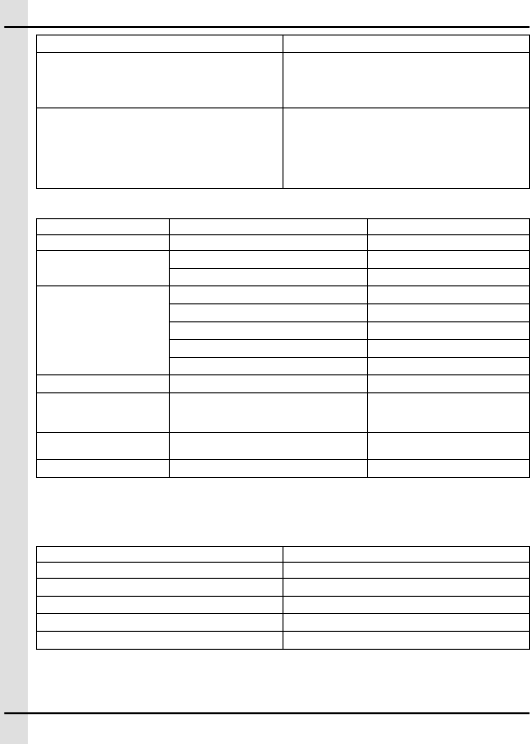
4Troubleshooting
Problem Solution
The KP-8IN-1REL or
TP-8IN-1REL or TR-
2IN-1REL does not
communicate
Verify if the controller is powered up
Verify if there is any activity on the communication bus by looking at the LEDs: AUTOMA-
TION-RX, AUTOMATION-TX, SAFETY-RX, SAFETY-TX.
Verify if the network link is installed correctly: Terminal A fromThe KP-8IN-1REL or TP-
8IN-1REL or TR-2IN-1REL to the Main Controller terminal A, Terminal B from The KP-
8IN-1REL or TP-8IN-1REL or TR-2IN-1REL to the Main Controller terminal B
Verify if the network communication is installed in daisy chain.
Verify if your end of line (EOL) are set correctly on your network.
Verify if the network link is cut (either the wire is cut or the protections are activated).
Verify if there is a short-circuit on the network link between terminal A and B.
Verify if the network link length is below 4000 feet (1200m) with the recommended gage.
Measure the voltage between terminal 24V and GND. The voltage must be at least 16V.
If the problem persists, contact your dealer or GSI Electronics.
The KP-8IN-1REL or
TP-8IN-1REL or TR-
2IN-1REL does not
power up
Verify if the LED "3.3V" or "5V" is activated on PCB-434.
Measure the voltage between terminal 24V and GND. The voltage must be at least 16V.
Verify if the power link is installed correctly: Terminal 24V from The KP-8IN-1REL or TP-
8IN-1REL or TR-2IN-1REL to the Main Controller terminal 24V, Terminal GND from The
KP-8IN-1REL or TP-8IN-1REL or TR-2IN-1REL to the Main Controller terminal GND.
Verify if the power link is cut (wire is cut).
Verify if the power link length is below 300 feet (1000m) with the recommended gage.
If the problem persists, contact your dealer or GSI Electronics.
The KP-8IN-1REL or
TP-8IN-1REL or TR-
2IN-1REL does not
still power up
Verify if the LED "3.3V" or "5V" is activated on PCB-434.
Measure the voltage between terminal 24V and GND. The voltage must be at least 16V.
Verify if the power link is installed correctly: Terminal 24V from The KP-8IN-1REL or TP-
8IN-1REL or TR-2IN-1REL to the Main Controller terminal 24V, Terminal GND fromThe
KP-8IN-1REL or TP-8IN-1REL or TR-2IN-1REL to the Main Controller terminal GND.
Verify if the power link is cut (wire is cut).
Verify if the power link length is below 300 feet (1000m) with the recommended gage.
If the problem persists, contact your dealer or GSI Electronics.
Relay does not acti-
vate the load
Verify if the LED 4 is activated on PCB-434.
Verify the wiring if the right contact is used correctly.
Verify if the load does not activate the protection. The current must be below 5A and
higher than 0.1A.
If there is an overload, find out the issue and solve it and reset the electronic fuse by
resetting it on the Main controller software.
895-00695 25
Chapter 4: Troubleshooting
Verify if the load link is not cut.
Verify if a voltage supply reach the terminal RELAY-COM.
If the problem persists, contact your dealer or GSI Electronics.
Issues with inputs
sensors
Verify if the sensor wiring is conformed to the wiring diagrams.
Verify if the sensor is connected at the right terminal.
Verify if the sensor configuration is set correctly on the Main Controller.
If the problem persists, contact your dealer or GSI Electronics.
Issues with the
24Vdc output
The 24Vdc output is not able to control the device. Ensure that the 24Vdc output does
not draw more than 50mA.
Verify if the sensor wiring is conformed to the wiring diagram.
If the problem persists, contact your dealer or GSI Electronics.
26 895-00695
ANavigating through the KP-8IN-
1REL
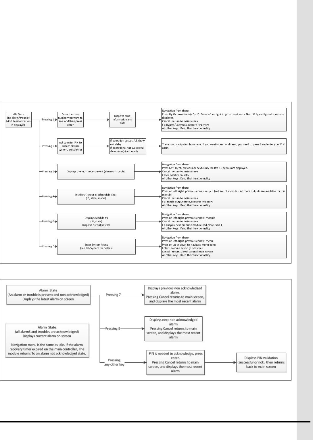
There are three different ways to navigate through the KP-8IN-1REL depending on the state.
Figure A-1 Navigation when state is idle
Figure A-2 Navigation when in alarm state
895-00695 27

BLED meaning
KP-8IN-1REL, TP-8IN-1REL, TR-2IN-1REL
LED identification Description
5V on PCB-434 Led active when the 5Vdc is present
3.3V on PCB-434 Led active when the 3.3Vdc is present
LED1 on PCB-434 Debug LEDs
LED2 on PCB-434
AUTOMATION-RX on PCB-434 Led blinks off during activity
AUTOMATION-TX on PCB-434 Led blinks off during activity
SAFETY-RX on PCB-434 Led blinks off during activity
SAFETY-TX on PCB-434 Led blinks off during activity
LED 4 on PCB-434 Led active when the relay is activated
LED1 on PCB-435 Leds Feedback for 24V and Comm. Status
LED2 on PCB-435
LED3 on PCB-435
LED4 on PCB-435
LED5 on PCB-435
LED6 on PCB-435
LED7 on PCB-435
LED8 on PCB-435
LED9 on PCB-435 Debug LEDs (and board ID)
LED10 on PCB-435
895-00695 29

NOTES
30 895-00695

CList of terminals
KP-8IN-1REL, TP-8IN-1REL, TR-2IN-1REL
Terminal name Description
RELAY - COM Relay input, the COM (Common) is the voltage source
needed to switch
RELAY - NO Relay output, When a relay contact is normally open
(NO), there is an opened contact when the relay is not
energized.
RELAY - NC Relay output, When a relay contact is Normally Closed
(NC), there is a closed contact when the relay is not
energized.
FUNCTIONAL EARTH Functional Ground Terminal Primarily used for func-
tional earth terminals which are generally associated
with test and measurement circuits. These terminals
are not for safety earthing purposes but provide an
earth reference point.
AUTOMATION - 24V Communication bus 1 - Power supply 24Vdc
AUTOMATION - A Communication bus 1 - Signal A of RS485
communication
AUTOMATION - B Communication bus 1 - Signal B of RS485
communication
AUTOMATION - GND Communication bus 1 - Power supply return
SAFETY - 24V Communication bus 2 - power supply 24Vdc
SAFETY - A Communication bus 2 - Signal A of RS485
communication
SAFETY - B Communication bus 2 - Signal B of RS485
communication
SAFETY - GND Communication bus 2 - Power supply return
IN(x) Analog inputs can set in 0-5V mode, in dry contact
mode, in 4-20mA mode, in temperature mode. Inputs
are used for sensors : temperature probes, humidity
probes, static pressure probes, water meters, dry
contacts.
GND(x) close to IN(x) Analog inputs returns. Inputs are used for sensors :
temperature probes, humidity probes, static pressure
probes, water meters, dry contacts.
24Vout 24Vdc output, 50mA
895-00695 31

NOTES
32 895-00695
DTechnical Specifications
Weight and dimensions
KP-8IN-1REL Weight 861,83 grams (1.90 lbs)
TP-8IN-1REL Weight 861,83 grams (1.90 lbs)
TR-8IN-1REL Weight 816.47 grams (1.80 lbs)
Enclosure dimensions Height 178 mm (7 inches)
Width 229 mm (9 inches)
Depth 76.2 mm (3 inches)
Clearance around the
enclosure
Top 152mm (6 inches)
Bottom 152mm (6 inches)
Sides 152mm (6 inches)
Table D-1 Safety ratings
Inputs:
KP-8IN-1REL Supply Input 24/28Vdc, 5.62W
TP-8IN-1REL Supply Input 24/28Vdc, 4.72W
TR-2IN-1REL Supply Input 24/28Vdc, 4.3W
Outputs:
Motor/inductive loads 5 A MAX
(Nb of Units = Max current rating divide by the max current of the fan multiply by
its service factor will give you the number of this fan type the relay can drive)
For example, 5A / (2.5 A * 1.5 SF) = 1.3, relay can drive up to 1 fan Minimum
load of 0.2A
50/60Hz 120Vac ,1/6HP (124W)
Resistive loads (electric heat-
ing element)
150Vac Max. / 28/24 VAC/DC, 5A max. Minimum load of 0.2A
Tungsten loads loads (incan-
descent and heat lamp)
120 Vac, 2A max.
Minimum load of 0.2A
DC loads 24Vdc, 5A max.
(The current reading is not available in DC) Minimum load of 0.2A )
Table D-2 Functional ratings
Inputs:
Temperature Compliant to GSIE temperature probes, Accuracy of ±0.1ºC in a normal operation,
Allowable loss of performance in a noisy environment:
895-00695 33

Appendix D: Technical Specifications
Table D-2 Functional ratings (cont'd.)
Accuracy of ±0.65ºC from initial reading with a fixed resistor of 1% precision used for testing
purpose.
Analog 0-5 Volts Sensor must be able to drive a 2k Ohms load, which means the sensor must drive at least
2.5mA to ensure correct readings. Accuracy of ±30mV in a normal operation,
Allowable loss of performance in a noisy environment:
Accuracy of ±80mV from initial reading with a voltage source of 1% precision used for test-
ing purpose.
Analog 4-20mA Sensor must be able to drive a 120 Ohms load
Maximum rating: 20.8mA, 2.5V
Accuracy of ±0.2mA in a normal operation
Allowable loss of performance in a noisy environment:
Accuracy of ±0.4mA from initial reading with a current source of 1% precision used for test-
ing purpose.
Dry contact Close contact resistance must be lower than 200 Ohms
Open contact resistance must be higher than 100k Ohms
Water meter,
Pulse speed
Max 100Hz, pulse width minimum of 3.2ms
Max 100 Ohms (close contact) and min. 100k Ohms (open contact) including the value of
the wire resistance
Relay outputs with
current sensing
input
Accuracy of ±0.5A for AC load <5A in a normal environment
Allowable loss of performance in a noisy environment:
Accuracy of ±0.75A from initial reading with a load of 1% precision used for testing purpose
Outputs:
24Vdc 24 Vdc, 50 mA max
Operational ratings
Operating
Temperature
-40 to 40°C (-40 to 104°F)
Storage
Temperature
-20 to 50°C (-4 to 122°F)
Environment Type Indoor and outdoor use
Pollution Degree 2
Installation
Category
2
Altitude 2000 Meters Max. (6561 Ft. Max)
Operating Rela-
tive Humidity
(maximum)
-40 to 0°C (-40 to 32°F) Non condensing
0 to 10°C (32 to 50°F) Non condensing
10 to 30°C (50 to 86°F) 95 % (± 3 %) Non condensing
30 to 40°C (86 to 104°F) 95 % (± 3 %) Non condensing
34 895-00695
Appendix D: Technical Specifications
Table D-2 Functional ratings (cont'd.)
IP rating (IEC
60529)
66
Nema Rating
(Nema 250)
4X
Flame Rating
(UL94)
5VA V-0
Flame Rating (IEC
60695 or IEC
60707)
FV-0
IK rating (degree
of mechanical pro-
tection - impact,
IEC 62262)
08
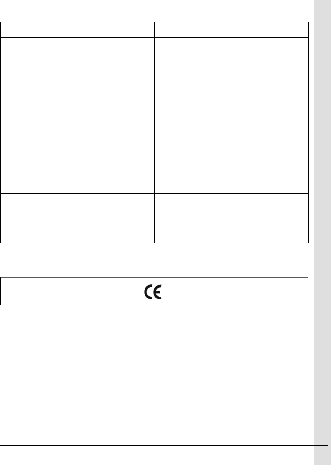
Table D-3 Telecommunication ratings for RFID module (Only on KP-8IN-1REL and TR-2IN-1REL)
Protocol Handling ISO15693
Output Power +20 dBm (100 mW)
System Clock Fre-
quency Output
13.56MHz
Equipment type
(ETSI EN 301
489-3)
III Others : Identification/Access control
Class type (ETSI
EN 301 489-3)
2 (Medium reliable SRD communication media; e.g. causing inconvenience
to persons, which cannot simply be overcome by other means)
895-00695 35

NOTES
36 895-00695
ESafety Characteristics and
Certification
Safety characteristics
The controllers are Safety Class I according to IEC classification and has been designed to meet the
requirements of UL 61010-1 third edition, CAN/CSA-C22.2 nº 61010-1 third edition, EN 61010-1: 2010
(Safety Requirements for Electrical Equipment for Measurement, Control and Laboratory Use). It is an
Installation Category II intended for operation from a normal single phase supply.
The controllers have been tested in accordance with IEC61010-1 and have been supplied in a safe condi-
tion. This instruction manual contains some information and warnings which have to be followed by the
user to ensure safe operation and to retain the instrument in a safe condition.
These Safety EU directives were followed:
2014/35/EU The low voltage directive (LVD)
2014/30/EU The Electromagnetic compatibility directive (EMC)
NOTE: KP-8IN-1REL, TP-8IN-1REL, TR-2IN-1REL plastic Enclosure is certified to use rigid tubing up to
1 inch.
EMC characteristics — emission standards
The controllers have been designed to meet the requirements of the EMC Directive 2014/30/EU, the FCC
directives, the Industry Canada directives. The compliance was demonstrated by meeting the test limits
of the following standards:
EN 61000-6-4 (2007/A1:2011) Emission tests levels for industrial environment
EN61326-1 (2013) EMC product standard for Electrical Equipment for
Measurement, Control and Laboratory Use
IEC EN 60730-1 (2010): Automatic electrical controls for household and similar
use - Part 1: General requirements - EMC
requirements
FCC part 15 Subpart B Class A
EMC certification: ICES-001 Industrial, Scientific and Medical (ISM) Radio Fre-
quency Generators – class A
ETSI EN 301 489-1 V1.9.2 (2011-09) Electromagnetic compatibility and Radio spectrum
Matters (ERM); ElectroMagnetic Compatibility (EMC)
standard for radio equipment and services; Part 1:
Common technical requirements
ETSI EN 301 489-3 V1.6.1 (2013-06) Electromagnetic compatibility and Radio spectrum
Matters ERM); ElectroMagnetic Compatibility (EMC)
standard for radio equipment and services; Part 3:
Specific conditions for Short-Range Devices (SRD)
operating on frequencies between 9 kHz and 40 GHz
895-00695 37
Appendix E: Safety Characteristics and Certification
Test number Test name Standard Standard level
1Conducted emissions CISPR 11 : 2009 A1
(2010) FCC part 15, sub-
part B : 2012
Group 1, class A Class A
2 Radiated emissions CISPR 11 : 2009 A1
(2010) FCC part 15, sub-
part B : 2012
Group 1, class A Class A
EMC characteristics — immunity standards
The controllers have been designed to meet the requirements of the EMC Directive 2014/30/EU, the FCC
directives, the Industry Canada directives. The compliance was demonstrated by meeting the test limits
of the following standards:
EN61326-1 (2013) EMC product standard for Electrical Equipment for
Measurement, Control and Laboratory Use
EN 61000-6-2 (2006): Immunity tests levels for industrial environment
IEC EN 60730-1 (2010): Automatic electrical controls for household and similar
use - Part 1: General requirements - EMC
requirements
FCC part 15 Subpart B Class A
ETSI EN 301 489-1 V1.9.2 (2011-09) Electromagnetic compatibility and Radio spectrum
Matters (ERM); ElectroMagnetic Compatibility (EMC)
standard for radio equipment and services; Part 1:
Common technical requirements
ETSI EN 301 489-3 V1.6.1 (2013-06) Electromagnetic compatibility and Radio spectrum
Matters ERM); ElectroMagnetic Compatibility (EMC)
standard for radio equipment and services; Part 3:
Specific conditions for Short-Range Devices (SRD)
operating on frequencies between 9 kHz and 40 GHz
Test
number
Test name Standard Standard level
5Radiated, radio-fre-
quency, electromagnetic
field immunity test
EN61000-4-3 :
2006 A1 : 2007 A2
: 2010
Modulation: 80% AM at 1kHz, 80MHz - 1GHz: 10V/
m 1.4GHz-2 GHz: 3 V/m 2GHz-2.7GHz: 3V/m Per-
formance: A (A)
6 Immunity to conducted
disturbances, induced by
radio-frequency fields
EN61000-4-6 :
2008
Frequency test range : 150KHz and 80Mhz at
10Vrms Pause time: 0,5s (AC line, Earth, I/O con-
nections >3m) Performance A (A)
7Electrostatic discharge
immunity test
EN61000-4-2 :
2008
± 8 kV air ± 6kV contact Performance A (B)
8Electrical fast transient/
burst immunity test
EN 61000-4-4 :
2012
±2kV/5kHz on the main sector ±1kV/5kHz on the I/
O >3m Performance A (B)
9Surge immunity test EN61000-4-5 :
2005
On the main sector : L-PE : ±2kV L-L : ±1kV I/O : L-
PE : ±1kV L-L : ±1kV
10 Power frequency mag-
netic field immunity test
EN 61000-4-8 :
2009
30 A/m, Performance A (B)
The definitions of performance criteria are as follows:
38 895-00695
Appendix E: Safety Characteristics and Certification
• Performance criterion A — During test normal performance within the specification limits
• Performance criterion B — During test, temporary degradation, or loss of function or performance
which is self-recovering
• Performance criterion C — During test, temporary degradation, or loss of function or performance
which requires operator intervention or system reset occurs.
The performance level A may be replaced by a permissible loss of performance. Following parameters
define the permissible loss of performance during immunity test. These parameters will not affect or
degrade the functional performance of the product.
KP-8IN-1REL, TP-8IN-1REL, TR-
2IN-1REL element
Normal operation Allowable loss of performance
Analog input configured in tempera-
ture mode
Accuracy of ±0.1ºC Accuracy of ±0.65ºC from initial
reading with a fixed resistor of 1%
precision used for testing purpose.
Analog input configured in 4-20mA
mode
Accuracy of ±0.2mA Accuracy of ±0.4mA from initial
reading with a current source of 1%
precision used for testing purpose.
Analog input configured in 0-5V
mode
Accuracy of ±30mV Accuracy of ±80mV from initial
reading with a voltage source of 1%
precision used for testing purpose.
Relay outputs with current sensing Accuracy of ±0.5A for AC load <5A Accuracy of ±0.75A from initial
reading with a load of 1% precision
used for testing purpose
OLED display No visual degradation No visual degradation
RS485 link 1 communication frame loss 3 consecutive communication
frames losses
Class type (ETSI EN 301 489-3)
Criteria During test After test
AOperate as intended No loss of
function For equipment type II the
minimum performance shall be 6
dB SINAD No unintentional
responses
Operate as intended For equipment
type II the communication link shall
be maintained No loss of function
No degradation of performance No
loss of stored data or user program-
mable functions
BMay be loss of function (one or
more) No unintentional responses
Operate as intended Lost function
(s) shall be self-recoverable No
degradation of performance No
loss of stored data or user program-
mable functions
RFID functional characteristics
The RFID module is designed and tested to meet the following requirements:
895-00695 39
Appendix E: Safety Characteristics and Certification
FCC 47 CFR Part 15.225 Operation within the band 13.110–14.010 MHz
RSS-210 Issue 8, December 2010, Annex 2.6 Spectrum Management and Telecommunications
Radio Standards Specification; Licence-exempt Radio
Apparatus (All Frequency Bands): Category I
Equipment
ETSI EN 300 330-2 V1.6.1 (2015-03) Electromagnetic compatibility and Radio spectrum
Matters (ERM); Short Range Devices (SRD); Radio
equipment in the frequency range 9 kHz to 25 MHz and
inductive loop systems in the frequency range 9 kHz to
30 MHz; Part 2: Harmonized EN covering the essential
requirements of article 3.2 of the R Directive
Environment characteristics
Parameter Condition Value
Environment Location Inside and outside
Temperature Operating -40 to 40°C (-40 to 104°F)
Storage -20 to +50 °C (-4 to +122 °F)
Humidity (Maximum
Relative)
-40 to 0°C (-40 to 32°F) Non condensing
0 to 10 °C (32 to 50 °F) Non condensing
10 to 30 °C (50 to 86 °F) 95 % (± 3%) Non condensing
30 to 40 °C (86 to 104 °F) 95 % (± 3%) Non condensing
Storage Non condensing
Altitude 2000 Meters Max. (6561 Ft. Max)
Electromagnetic
Environment
EN/IEC61326-1 IEC EN 60730-1
EN 61000-6-4 EN 61000-6-2 ETSI
EN 301 489-1 ETSI EN 301 489-3
Enclosure Protection Nema 250 : type 4xIP : 66, ref :
IEC60529
Impact rating (IK) 08
The controllers were tested under IEC60068-1 (Environmental testing - Part 1: General and guidance)
Environmental characteristics
These Environmental EU directives were followed:
2011/65/EU The RoHS 2 Directive
2012/19/EU The WEEE 2 Directive
1907/2006/EU The REACH regulation
2006/66/EC The Battery Directive
94/62/EC Packaging and packaging waste Directive
97/129/EC Packaging material identification Directive
40 895-00695

FEC Declaration of Conformity (In
accordance with EN ISO 17050-1 2004)
We: GSI Electronics Inc.
Of: 5200, Armand-Frappier, Saint-Hubert (Québec), Canada, J3Z 1G5
In accordance with the following directives:
2014/35/EU The Low Voltage Directive (LVD)
2014/30/EU The Electromagnetic Compatibility Directive (EMC)
1999/5/EC The Radio & Telecommunication Terminal Equipment Directive (R&TTE)
2011/65/EU The RoHS 2 Directive
2012/19/EU The WEEE 2 Directive
1907/2006/EC The REACH regulation
2006/66/EC The Battery Directive
94/62/EC Packaging and packaging waste Directive
97/129/EC Packaging material identification Directive
Hereby declare that:
Equipment: The Modules KP-8IN-1REL, TP-8IN-1REL, TR-2IN-1REL are used in an Edge system or
AA128 Touch system. The modules are used in a farm system network designed to monitor and to control
of a farm environment. The main functions of monitoring or controlling are: ventilation control, heating
control, lighting control, animal feeding control, scale control, quality air control, alert function.
Model numbers:
KP-8IN-1REL, TP-8IN-1REL, TR-2IN-1REL
is in conformity with the applicable requirements of the following documents:
Directive Ref. No Title Edition/date
LVD EN 61010-1 Safety requirements for
electrical equipment for
measurement, control,
and laboratory use
Part 1: General
requirements
2010
RETSI EN 300 330-2 Electromagnetic compati-
bility and Radio spectrum
Matters (ERM); Short
Range Devices (SRD);
Radio equipment in the
V1.6.1 (2015-03)
895-00695 41

frequency range 9 kHz to
25 MHz and inductive
loop systems in the fre-
quency range 9 kHz to 30
MHz; Part 2: Harmonized
EN covering the essential
requirements of article 3.2
of the R Directive
EMC ETSI EN 301 489-1 Electromagnetic compati-
bility and Radio spectrum
Matters (ERM); Electro-
Magnetic Compatibility
(EMC) standard for radio
equipment and services;
Part 1: Common technical
requirements
V1.9.2 (2011-09)
EMC ETSI EN 301 489-3 Electromagnetic compati-
bility and Radio spectrum
Matters ERM); Electro-
Magnetic Compatibility
(EMC) standard for radio
equipment and services;
Part 3: Specific conditions
for Short-Range Devices
(SRD) operating on fre-
quencies between 9 kHz
and 40 GHz
V1.6.1 (2013-06)
EMC EN 61326-1 Electrical equipment for
measurement, control
and laboratory use - EMC
requirements
2013
EMC EN 61000-6-2 Immunity tests levels for
industrial environment
EN 61000-4-2
EN 61000-4-3
EN 61000-4-4
EN 61000-4-5
EN 61000-4-6
EN 61000-4-8
2006
2009
2006 A1 (2007) A2 (2010)
2012
2014
2008
2010
EMC EN 61000-6-4 Emission tests levels for
industrial environment
CISPR11 /EN 55011
2009 + A1: 2010
2007/A1:2011
2006 +A1 (2009)+
A2 (2009)
2008
42 895-00695
(2009)+A1 (2010)
EMC IEC EN 60730-1 Automatic electrical con-
trols for household and
similar use - Part 1: Gen-
eral requirements- EMC
requirements
Immunity and emission
part
CISPR11 /EN 55011
EN 61000-4-2
IEC EN 61000-4-3
EN 61000-4-4
IEC EN 61000-4-5
IEC EN 61000-4-6
EN 61000-4-8
2010
(2009)+A1 (2010)
2009
2006 A1 (2007) A2 (2010)
2012
2014
2008
2010
RoHS EN 50581 Technical documentation
for the assessment of
electrical and electronic
products with respect to
the restriction of hazard-
ous substances
2012
GSI Electronic Inc. hereby declares that the equipment named above has been designed to
comply with the relevant sections of the above referenced specifications. The unit complies with
all applicable Essential Requirements of the Directives.
895-00695 43

NOTES
44 895-00695

GFCC part 15 statement
Statement regarding the importation of radio frequency devices capable of causing harmful interference.
GSI Electronics Inc. develops, manufactures and distributes innovative technological products for the
agricultural industry. Our unique expertise allows us to offer accurate, simple and diverse electronic, data
processing and mechanical solutions for improving agricultural production.
Electronic controllers use radiation-emitting technology: RFID (Radio Frequency Identification). This wire-
less technology is used by GSI Electronics to control the access to the barn. Electronic controllers are
classed as intentional radiators (FCC 47-part 15-Subpart C). The RFID Module respects the emission lim-
itations and the performances required by the standards FCC 15.225, RSS-210 Annex 2.6, ETSI 300
330. Electronic controllers are used in a production context and in an industrial context (FCC 47-part 15-
Subpart B- Class A).
GSI Electronics Inc. hereby declares that the equipment has been tested and found to comply with the
limits for a Class A digital device, pursuant to part 15 of the FCC Rules.
This device complies with part 15 of the FCC Rules. Operation is subject to the following two conditions:
(1) This device may not cause harmful interference, and (2) this device must accept any interference
received, including interference that may cause undesired operation.
These limits are designed to provide reasonable protection against harmful interference when the equip-
ment is operated in a commercial environment. This equipment generates, uses, and can radiate radio
frequency energy and, if not installed and used in accordance with the instruction manual, may cause
harmful interference to radio communications. Operation of this equipment in a residential area is likely to
cause harmful interference in which case the user will be required to correct the interference at his own
expense.
If this equipment does cause harmful interference to radio or television reception, which can be deter-
mined by turning the equipment off and on, the user is encouraged to try and correct the interference by
one or more of the following measures:
• Reorient or relocate the receiving antenna (RFID Module).
• Increase the separation between the equipment and receiver.
• Connect the equipment into an outlet on a circuit different from that to which the receiver is
connected.
• Consult GSI Electronics
895-00695 45

NOTES
46 895-00695

HFCC RF exposure statement
Statement regarding the importation of radio frequency devices capable of causing radiation exposure
GSI Electronics Inc. develops, manufactures and distributes innovative technological products for the
agricultural industry. Our unique expertise allows us to offer accurate, simple and diverse electronic, data
processing and mechanical solutions for improving agricultural production.
The RFID module uses radiation-emitting technology: emission at 13.56-MHz.The RFID module is
classed as intentional radiators (FCC 47-part 15-Subpart C). This equipment complies with FCC radiation
exposure limits set forth for an uncontrolled environment. This equipment should be installed and oper-
ated with minimum distance 20 cm between the radiator and your body. This transmitter must not be co-
located or operating in conjunction with any other antenna or transmitter.
895-00695 47

NOTES
48 895-00695

IInnovation, Science and Economic
Development Canada ICES-003 Com-
pliance CAN ICES-3 (A)/NMB-3(A)
This device complies with Industry Canada licence-exempt RSS standard(s). Operation is subject to the
following two conditions: (1) this device may not cause interference, and (2) this device must accept any
interference, including interference that may cause undesired operation of the device.
Le présent appareil est conforme aux CNR d'Industrie Canada applicables aux appareils radio exempts
de licence. L'exploitation est autorisée aux deux conditions suivantes : (1) l'appareil ne doit pas produire
de brouillage, et (2) l'utilisateur de l'appareil doit accepter tout brouillage radioélectrique subi, même si le
brouillage est susceptible d'en compromettre le fonctionnement.
Innovation, Science and Economic Development Canada ICES-003 Compliance CAN ICES-3 (A)/NMB-3
(A)
IMPORTANT: Radiation Exposure Statement: This equipment complies with IC radiation exposure limits
set forth for an uncontrolled environment. This equipment should be installed and operated
with minimum distance 20cm between the radiator and your body.
IMPORTANT: Déclaration d'exposition aux radiations: Cet équipement est conforme aux limites d'exposi-
tion aux rayonnements IC établies pour un environnement non contrôlé. Cet équipement
doit être installé et utilisé avec un minimum de 20 cm de distance entre la source de
rayonnement et votre corps.
895-00695 49

NOTES
50 895-00695

JFDA declaration
Statement regarding the importation of devices and public health hazard directives from FDA (U.S. Food
and Drug Administration)
GSI Electronics Inc. develops, manufactures and distributes innovative technological products for the
agricultural industry. Our unique expertise allows us to offer accurate, simple and diverse electronic, data
processing and mechanical solutions for improving agricultural production.
GSI Electronics’ controllers are shipping under 9032.89.60.30 Canada (Automatic Regulating or Control-
ling Instruments & Apparatus). Electronic controllers are used to monitor and to control animal environ-
ment in a barn: ventilation function; heating function; lightning function; alert system function. Electronic
controllers can be used to control the food distribution and to scale animals.
Electronic controllers do not use laser technologies. Electronic controllers use liquid crystal display (LCD)
or Light-emitting diodes (LED). It is important to note also that electronic controller incorporating Liquid
Crystal Displays (LCD) or Light-emitting diodes (LED) are not capable of emitting x-radiation.
Electronic controllers use radiation-emitting technology: RFID (Radio Frequency Identification). This wire-
less technology is used by GSI Electronics to control the access to the barn. Electronic controllers are
classed as intentional radiators (FCC 47-part 15-Subpart C). The RFID Module respects the emission lim-
itations and the performances required by the standards FCC 15.225, RSS-210 Annex 2.6, ETSI 300
330. Electronic controllers are used in a production context and in an industrial context (FCC 47-part 15-
Subpart B- Class A).
GSI Electronics devices are not used in contact with animal food. Electronic controllers do not manipulate
vaccines or drugs.
As such these products and are not subject to the FDA standards and do not pose a public health hazard.
895-00695 51

NOTES
52 895-00695

KReduction of Hazardous
Substances
REACH directive
The REACH directive addresses the production and use of chemical substances, and their potential
impacts on both human health and the environment. On June 1, 2007, the European Commission promul-
gated new legislation that covers the registration, evaluation, authorization and restriction of chemical
within the European Union community. This new regulation is commonly known as REACH, an acronym
for Registration, Evaluation and Authorization of Chemicals (EC Regulation 1907/2006).
GSI Electronics supports the underlying goals of REACH, which are consistent with our own commitment
to promote the responsible manufacturing, use and handling of chemicals. GSI Electronics uses and pro-
motes components suppliers or components manufacturers who will meet the pre-registration deadline
for all chemical substances in quantities greater than one metric ton. The information provided here is
accurate to the best of our knowledge at the present time.
RoHS directive
The Restriction ofHazardous Substances Directive 2002/95/EC, RoHS, Directive on the restriction of the
use of certain hazardous substances in electrical and electronic equipment, was adopted in February
2003 by the European Union. The RoHS directive took effect on 1 July 2006, and is required to be
enforced and become law in each member state. This directive restricts (with exceptions) the use of six
hazardous materials in the manufacture of various types of electronic and electrical equipment: Lead
(Pb), Mercury (Hg), Cadmium (Cd), Hexavalent chromium (Cr6+), Polybrominated biphenyls (PBB), Poly-
brominated diphenyl ether (PBDE). The RoHS 2 directive (2011/65/EU) is an evolution of the original
directive and became law on 21 July 2011 and took effect 2 January 2013. It addresses the same sub-
stances as the original directive while improving regulatory conditions and legal clarity.
GSI Electronics hereby certifies that all components are RoHS Compliant and fulfills the definition and
restrictions defined under Directive 2011/65/EU of the European Parliament and of the Council of June 8,
2011 on the restriction of the use of certain hazardous substances in electrical and electronic equipment
(EEE). The information provided here is accurate to the best of our knowledge at the present time.
The RoHS declaration is available, contact GSI Electronics or the European representative.
Battery directive
The Battery Directive, Directive 2006/66/EC (Previous Directive, Directive 91/157/EEC), of the European
Parliament regulates the manufacture, the disposal, the recycling of batteries and accumulators in the
European Union.
GSI Electronics uses Lithium cell button in a light industrial context or industrial context. GSI Electronics
encourages the batteries and accumulators recycling.
895-00695 53

NOTES
54 895-00695
LDisposal and Recycling
Information
North America : Canada
As the concern for the volume of electronic waste grows, a number of Provinces in Canada have passed
regulations since 2006 to divert electronics waste from the landfills and to protect the environment. These
waste diversion regulations require manufacturers of covered electronic devices to participate in
approved electronic product stewardship programs. The programs allow consumers and businesses to
drop off eligible electronic devices for recycling, free of charge at numerous depots throughout the
Province.
For more detailed information about the recycling of the device or batteries, contact your local city office,
the household waste disposal service, or the retail store where you purchased this device. These collec-
tion points are accessible free of charge.
North America : United States
For more detailed information about the recycling of the device or batteries, contact your local city office,
the household waste disposal service, or the retail store where you purchased this device. These collec-
tion points are accessible free of charge.
European markets – WEEE Directive
The Waste Electrical and Electronic Equipment Directive (WEEE Directive) is the European directive on
waste electrical and electronic equipment (Directive 2002/96/EC) which, together with the RoHS Directive
2002/95/EC, became European Law in February 2003. The WEEE Directive set collection, recycling and
recovery targets for all types of electrical products. And later the WEEE Recast Directive 2012/19/EU
requiring producers of electronic equipment to manage and finance the collection, reuse, recycling and
appropriately treat WEEE that the producer places on the EU market after 13th August 2005.
As required by the legislation, products sold in the EU are marked with the "crossed out wheelie bin"
symbol. GSI Electronics uses the symbol based on the EN 50419:2005 CENELEC standard. The bottom
bar certifies the product concerned was placed on the market after 13th August 2005. Cables or compo-
nents and sub-assemblies contained within the in the product will not be marked.
Instructions for disposal of waste equipment by users
The "crossed out wheelie bin" symbol on the device (and any included batteries) indicates that they
should not be disposed of as normal household garbage. Do not dispose of your device or batteries as
unsorted municipal waste. The device (and any batteries) should be handed over to a certified collection
point for recycling or proper disposal at the end of their life.
For more detailed information about the recycling of the device or batteries, contact your local city office,
the household waste disposal service, or the retail store where you purchased this device. These
895-00695 55

Appendix L: Disposal and Recycling Information
collection points are accessible free of charge. All products with this sign must be brought to these collec-
tion points.
The disposal of this device is subject to the Waste from Electrical and Electronic Equipment (WEEE)
directive of the European Union. The reason for separating WEEE and batteries from other waste is to
minimize the potential environmental impacts on human health of any hazardous substances that may be
present.
There are two ways available to dispose of waste:
• Public system— contact your municipality or the nearest collection site to dispose of Electrical and
electronic Equipment waste
• Private system— For a Return Material Authorization for Disposal of Waste Equipment, contact cus-
tomer support at 1-877-926-2777 or by e-mail at mtl_techsupport@agcocorp.com.
56 895-00695
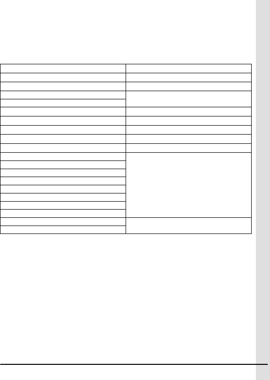
MProduct material composition
KP-8IN-1REL
Material Weight Weight ratio (%)
Lbs Grams
Packaging material 0,50 226,80 20,83
Plastic material 1,25 566,99 52,08
Electronic Circuits 0,55 249,48 22,93
Cable 0,05 22,68 2,08
Metal 0,05 22,68 2,08
TP-8IN-1REL
Material Weight Weight ratio (%)
Lbs Grams
Packaging material 0,50 226,80 20,83
Plastic material 1,25 566,99 52,08
Electronic Circuits 0,55 249,48 22,93
Cable 0,05 22,68 2,08
Metal 0,05 22,68 2,08
TR-2IN-1REL
Material Weight Weight ratio (%)
Lbs Grams
Packaging material 0,50 226,80 21,74
Plastic material 1,25 566,99 54,35
Electronic Circuits 0,45 204,12 19,57
Cable 0,05 22,68 2,17
Metal 0,05 22,68 2,17
895-00695 57

NOTES
58 895-00695
NPackaging characteristics
The following directives were followed during the packaging process
2011/65/EU The RoHS 2 directive
2012/19/EU The WEEE 2 directive
1907/2006/EU The REACH regulation
2006/66/EC The battery directive
94/62/EC Packaging and packaging waste directive
97/129/EC Packaging material identification directive
Packaging is only in cardboard to respect international standards about environment standards:
EN 13428 Packaging - Requirements specific to manufacturing
and composition - Prevention by source reduction
EN 13429 Packaging - Reuse
EN 13430 Packaging - Requirements for packaging recoverable
by material recycling
EN 13431 13431 Packaging - Requirements for packaging recov-
erable in the form of energy recovery, including specifi-
cation of minimum inferior calorific value
EN 13432 Packaging - Requirements for packaging recoverable
through composting and biodegradation - Test scheme
and evaluation criteria for the final acceptance of
packaging
Packaging was tested under ISTA 3A (Packaged Products for Parcel Delivery System Shipment weighing
150 lbs or less – is a test used for simulating courier companies shipping environments).
Shipping, packaging and Lithium battery: packaging shall be capable of withstanding a 1.2 m drop test in
any orientation without damage to cells or batteries contained therein according to the International Civil
Aviation Organization (ICAO), the International Air Transport Association (IATA), the International Mari-
time Organization (IMO) requirements.
Handling symbols on packaging: the standard is ISO R/780 (Packaging - Pictorial marking for handling of
goods).
895-00695 59

NOTES
60 895-00695
OLow voltage cable specifications
Communication bus
The suggested cable is AlphaWire 45374 or with very similar specifications.
Table O-1 communication bus — communication cables
Item Description
Cable type Twisted and shielded
Minimum gauge 1 mm2 (18 AWG)
Maximum cable length (including cable extensions) 1200 meters (4000 feet)
Certification and type CSA, CMG FT4 type, 18 AWG, 600 V, 75 °C (167 °F)
UL, AWM or CM ttype, 18 AWG, 600 V, 75 °C (167 °F)
Characteristic Impedance 120 Ω +/- 12
Inductance 0.258 µH/ft, Nominal
Mutual Capacitance 12 pf/ft @1 kHz, Nominal
Velocity of propagation 75%
Conductor DCR 6.9 Ω/1000ft @20°C, Nominal
OA Shield DCR 1.8 Ω/1000ft @20°C, Nominal
Attenuation (Max dB/100ft) 0.13 @ 125 kHz
0.25 @ 500 kHz
0.36 @ 1 MHz
Number of Twists 2.4 Twists/foot (min)
Table O-2 DC Power cables
Item Description
Wire gauge 18 AWG 16* AWG 14 AWG 12 AWG 10 AWG
1 pair twisted
shielded
1 pair twisted
shielded
1 pair twisted
shielded
1 pair twisted
shielded
1 pair twisted
shielded
Max. length 150m (500 feet) 300m (1000
feet)
600m (2000
feet)
900m (3000
feet)
1200m (4000
feet)
Inductance
Nominal
0.17 μH/ft 0.174 μH/ft 0.16 μH/ft 0.16 μH/ft 0.14 μH/ft
ConductorDCR
@20°C,
Nominal
6.1 Ω/1000ft 3.6 Ω/1000ft 2.6 Ω/1000ft 1.63 Ω/1000ft 1.09 Ω/1000ft
Certification and
type
CSA, TEW type, 600 V, 105 °C (221 °F)
UL, 1015 type, 600 V, 105 °C (221 °F)
*The recommended cable is AlphaWire 6451- 2 pairs:
895-00695 61

Appendix O: Low voltage cable specifications
- 1 pair 18AWG twisted shielded for Communication;
- 1 pair 15AWG twisted shielded for Power
Table O-3 Other Low voltage cables
Item Description
Cable type Twisted and shielded
Minimum gauge 1 mm2 (18 AWG)
Maximum sensor cable length 150 m (500 feet)
• Sensor cables
• Potentiometer cables
• All other low voltage devices
62 895-00695
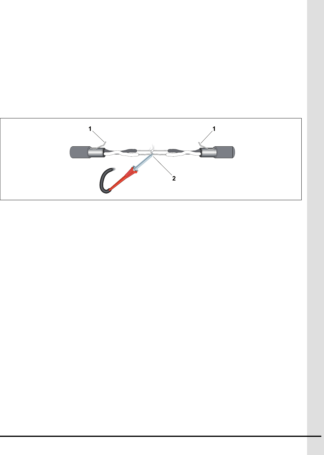
PExtending a cable
• Solder all joints. See number 2 in the following figure.
• Use heat shrink tubing
• Cut the ground wire. Do not connect it. see number 1 in the following figure
895-00695 63

NOTES
64 895-00695
QKP-8IN-1REL, TP-8IN-1REL, TR-
2IN-1REL - Product End-of-Life Disas-
sembly Instructions
This disassembly and recycling guidance provides general guidance for the disassembly of the refer-
enced product to remove components and materials requiring selective treatment, as defined by EU
directive 2002/96/EC and, Waste Electrical and Electronic Equipment (WEEE).
Models and descriptions
Table Q-1 List of product for which disassembly instructions are provided
Marketing name (GSI Electronics Part number) Description
KP-8IN-1REL,
TP-8IN-1REL
TR-2IN-1REL
Auxiliary modules
Table Q-2 Required tools
Tool Description Tool size
Phillips screw driver #1
Phillips screw driver #2
Flat-head screw driver Small
Flat-head screw driver Large
Side cutters —
895-00695 65
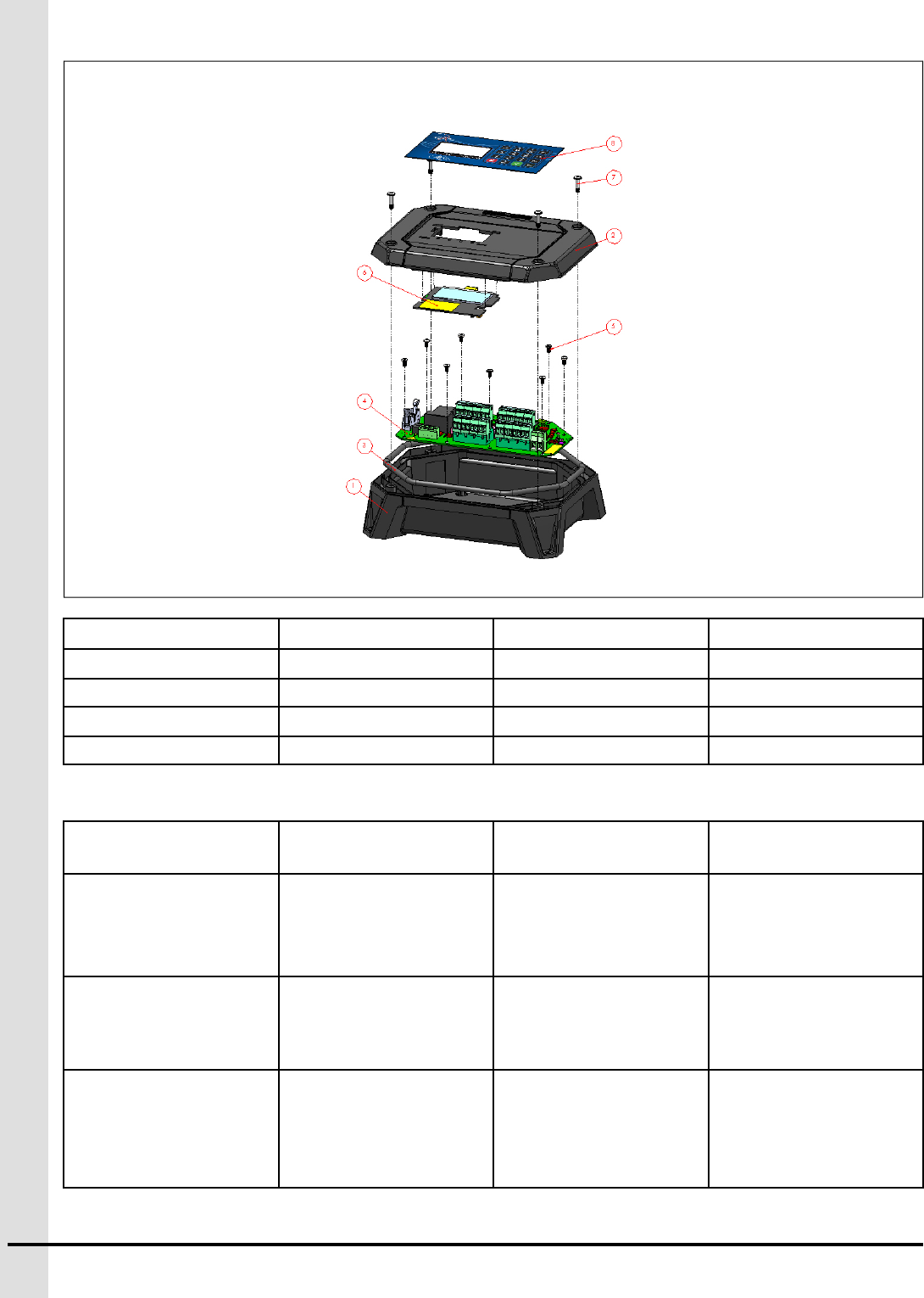
Item number Description Item number Description
1 Enclosure Bottom 5Screw SCREW,#6-19
2Enclosure Cover 6PCB-435
3 Gasket 7Screw M4-0.7,16mm
4PCB-434 8 Membrane
Items Requiring Selective Treatment
Item Description Notes Quantity of Items
Included in the product
Location
Printed Circuit Boards
(PCB) or Printed Circuit
Assemblies (PCA)
With a surface greater
than 10 square cm
2PCB-434 (item 4)
PCB-435 or PCB-414
(item 6)
Batteries All types including stand-
ard alkaline and lithium
coin or button style
batteries.
none
Mercury containing
components
For example, mercury in
lamps, display backlights,
scanner lamps, lamps,
lightning application,
switches, and batteries.
none
66 895-00695

Liquid Crystal Displays
(LCD)
With a surface greater
than 100 square cm and
all those back-lighted with
gas discharge lamps.
1 OLED on PCB-435 or
PCB-414 (item 6)
Cathode Ray Tubes
(CRT)
none
Capacitors / condensers Containing polychlori-
nated biphenyls PCB /
polychlorinated terphen-
yls PCT.
none
Electrolytic Capacitors /
Condensers
Measuring greater than
2.5cm in diameter or
height.
none
External electrical cables
and cords
none1
Gas Discharge Lamps none
Plastics containing Bromi-
nated Flame Retardants
none2
Components and parts
containing toner and ink,
including liquids, semi-
liquids (gel/paste) and
toner
none
Components and waste
containing asbestos
none
Components, parts and
materials containing
refractory ceramic fibres
none
Components, parts and
materials containing
radioactive substances
none
Components, parts and
materials containing
chlorofluorocarbons
(CFC), hydrochlorofluoro-
carbons (HCFC), hydro-
fluorocarbons (HFC),
hydrocarbons (HC)
none
12
895-00695 67
1. GSI Electronics does not provide the external electrical cable
2. All plastics used in this product are RoHS compliant and do not contain PBBs or PBDEs

Product disassembly process
Step Process
Remove External Electrical cables and internal Electri-
cal cables
1. Unscrew and remove the enclosure cover (item 2)
2. Remove the wires from the enclosure bottom (item
1), by unscrewing terminal blocks with a small flat-head
screwdriver and a large flat-head screwdriver.
3. Remove the cable between the PCB-434 (item 4)
and the PCB-435 or PCB-414 (item 6)
Printed Circuit Assembly 1. Unscrew and remove the enclosure cover (item 2)
2. Locate these PCBs: PCB-434 (item 4) PCB-435 or
PCB-414 (item 6)
3. Unscrew with a Philips screwdriver #1 and remove
the screws (item 5) from the PCB-434 (item 4)
4. Unfasten the PCB-435 or PCB-414 from the enclo-
sure cover 5. Remove the PCBs from the KP-8IN-
1REL, TP-8IN-1REL, TR-2IN-1REL
Remove the OLED Cables are unplugged
1. Unscrew and remove the enclosure cover (item 2)
2. Unfasten the PCB-435 or PCB-414 from the enclo-
sure cover
Recycle plastic 1. Unscrew and remove the enclosure cover (item 2)
2. From the enclosure bottom, remove the gasket(item
3)
3. Keep only plastic parts
4. Recycle the plastic enclosure and the plastic parts.
68 895-00695
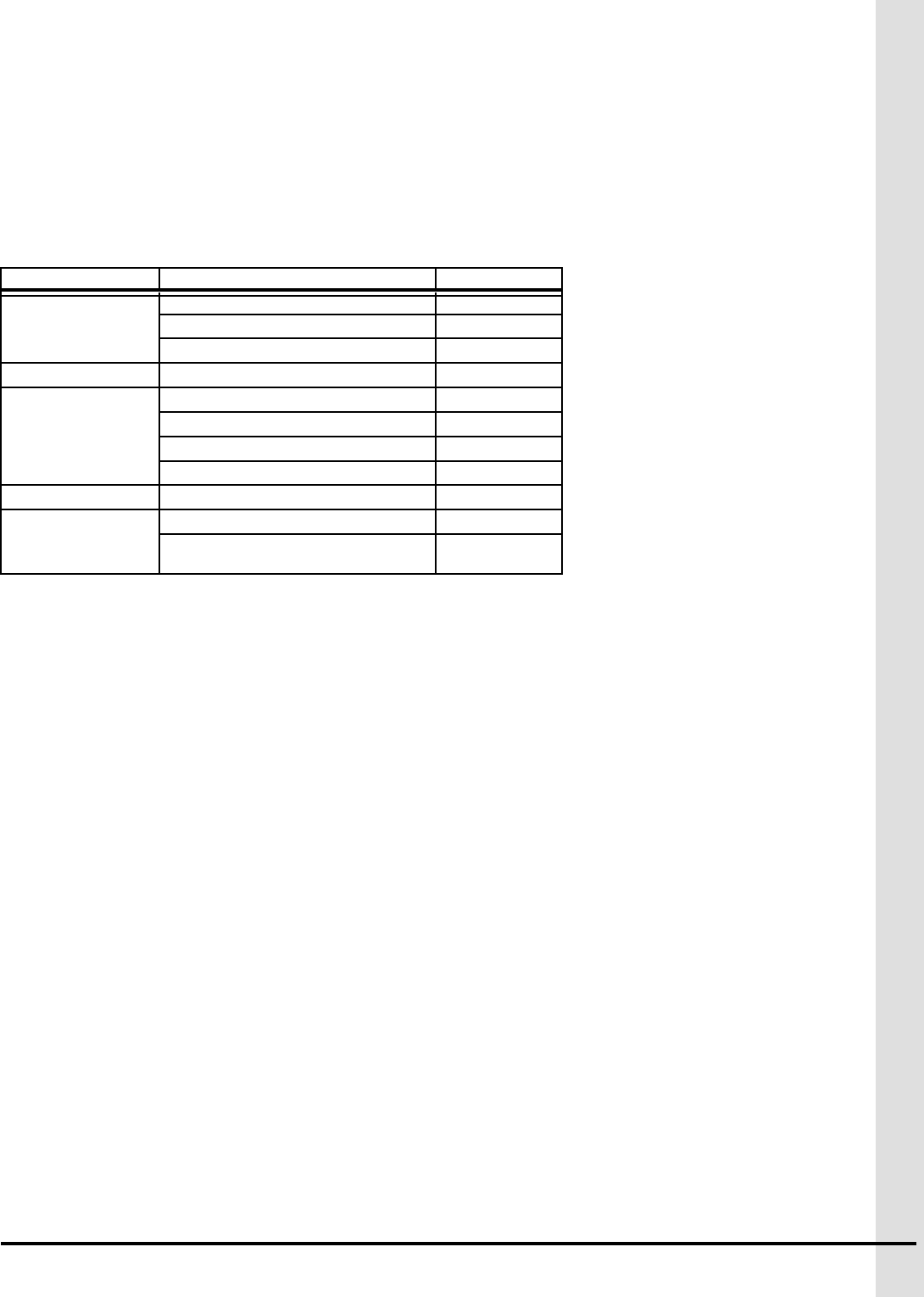
GSI Group, LLC Limited Warranty
The GSI Group, LLC (“GSI”) warrants products which it manufactures to be free of defects in materials and workmanship
under normal usage and conditions for a period of 12 months after sale to the original end-user or if a foreign sale, 14
months from arrival at port of discharge, whichever is earlier. The end-user’s sole remedy (and GSI’s only obligation) is to
repair or replace, at GSI’s option and expense, products that in GSI’s judgment, contain a material defect in materials or
workmanship. Expenses incurred by or on behalf of the end-user without prior written authorization from the GSI Warranty
Group shall be the sole responsibility of the end-user.
Warranty Extensions: The Limited Warranty period is extended for the following products:
Product Warranty Period
AP Fans and Flooring
Performer Series Direct Drive Fan Motor 3 Years
All Fiberglass Housings Lifetime
All Fiberglass Propellers Lifetime
AP/Cumberland Flex-Flo/Pan Feeding System Motors 2 Years
Cumberland
Feeding/Watering
Systems
Feeder System Pan Assemblies 5 Years **
Feed Tubes (1-3/4" and 2.00") 10 Years *
Centerless Augers 10 Years *
Watering Nipples 10 Years *
Grain Systems Grain Bin Structural Design 5 Years
Grain Systems
Farm Fans
Zimmerman
Portable and Tower Dryers 2 Years
Portable and Tower Dryer Frames and
Internal Infrastructure † 5 Years
* Warranty prorated from list price:
0 to 3 years - no cost to end-user
3 to 5 years - end-user pays 25%
5 to 7 years - end-user pays 50%
7 to 10 years - end-user pays 75%
** Warranty prorated from list price:
0 to 3 years - no cost to end-user
3 to 5 years - end-user pays 50%
† Motors, burner components and
moving parts not included.
Portable dryer screens included.
Tower dryer screens not included.
GSI further warrants that the portable and tower dryer frame and basket, excluding all auger and auger drive components,
shall be free from defects in materials for a period of time beginning on the twelfth (12th) month from the date of purchase
and continuing until the sixtieth (60th) month from the date of purchase (extended warranty period). During the extended
warranty period, GSI will replace the frame or basket components that prove to be defective under normal conditions of
use without charge, excluding the labor, transportation, and/or shipping costs incurred in the performance of this extended
warranty.
Conditions and Limitations:
THERE ARE NO WARRANTIES THAT EXTEND BEYOND THE LIMITED WARRANTY DESCRIPTION SET FORTH
ABOVE. SPECIFICALLY, GSI MAKES NO FURTHER WARRANTY OF ANY KIND, EXPRESS OR IMPLIED, INCLUDING,
WITHOUT LIMITATION, WARRANTIES OF MERCHANTABILITY OR FITNESS FOR A PARTICULAR PURPOSE OR
USE IN CONNECTION WITH: (I) PRODUCT MANUFACTURED OR SOLD BY GSI OR (II) ANY ADVICE, INSTRUCTION,
RECOMMENDATION OR SUGGESTION PROVIDED BY AN AGENT, REPRESENTATIVE OR EMPLOYEE OF GSI
REGARDING OR RELATED TO THE CONFIGURATION, INSTALLATION, LAYOUT, SUITABILITY FOR A PARTICULAR
PURPOSE, OR DESIGN OF SUCH PRODUCTS.
GSI shall not be liable for any direct, indirect, incidental or consequential damages, including, without limitation, loss of
anticipated profits or benefits. The sole and exclusive remedy is set forth in the Limited Warranty, which shall not exceed
the amount paid for the product purchased. This warranty is not transferable and applies only to the original end-user. GSI
shall have no obligation or responsibility for any representations or warranties made by or on behalf of any dealer, agent
or distributor.
GSI assumes no responsibility for claims resulting from construction defects or unauthorized modifications to products
which it manufactured. Modifications to products not specifically delineated in the manual accompanying the equipment at
initial sale will void the Limited Warranty.
This Limited Warranty shall not extend to products or parts which have been damaged by negligent use, misuse, altera-
tion, accident or which have been improperly/inadequately maintained. This Limited Warranty extends solely to products
manufactured by GSI.
Prior to installation, the end-user has the responsibility to comply with federal, state and local codes which apply to the
location and installation of products manufactured or sold by GSI.
9101239_1_CR_rev8.xml (revised January 2014)
895-00695 69
This equipment shall be installed in accordance with
the current installation codes and applicable
regulations which should be carefully followed in all
cases. Authorities having jurisdiction should be
consulted before installations are made.
1004 E. Illinois St.
Assumption, IL 62510-0020
Phone: 1-217-226-4421
Fax: 1-217-226-4420
www.gsiag.com
Agri-Alert is a part of GSI, a worldwide Brand of AGCO.
Copyright © 2015 by GSI Electronics
Printed in Canada