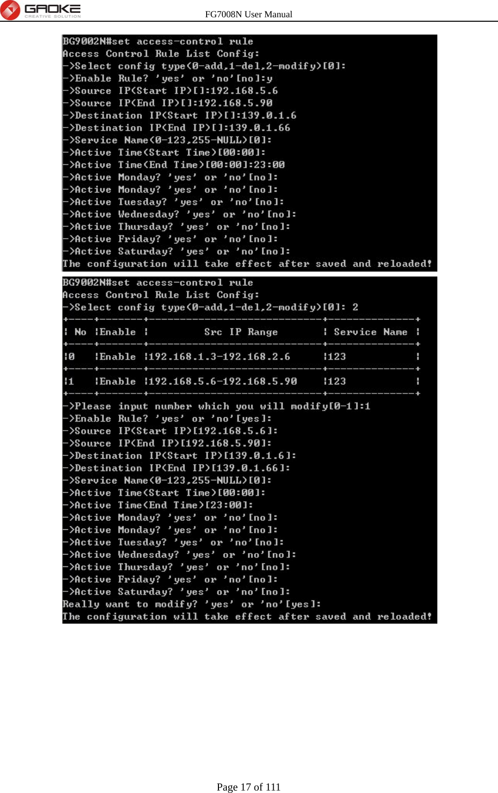
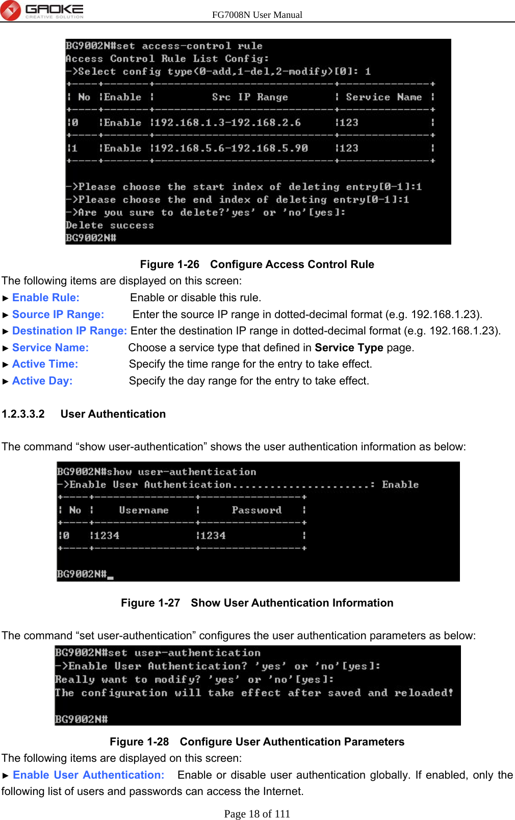
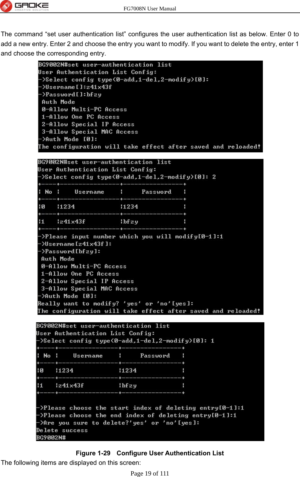
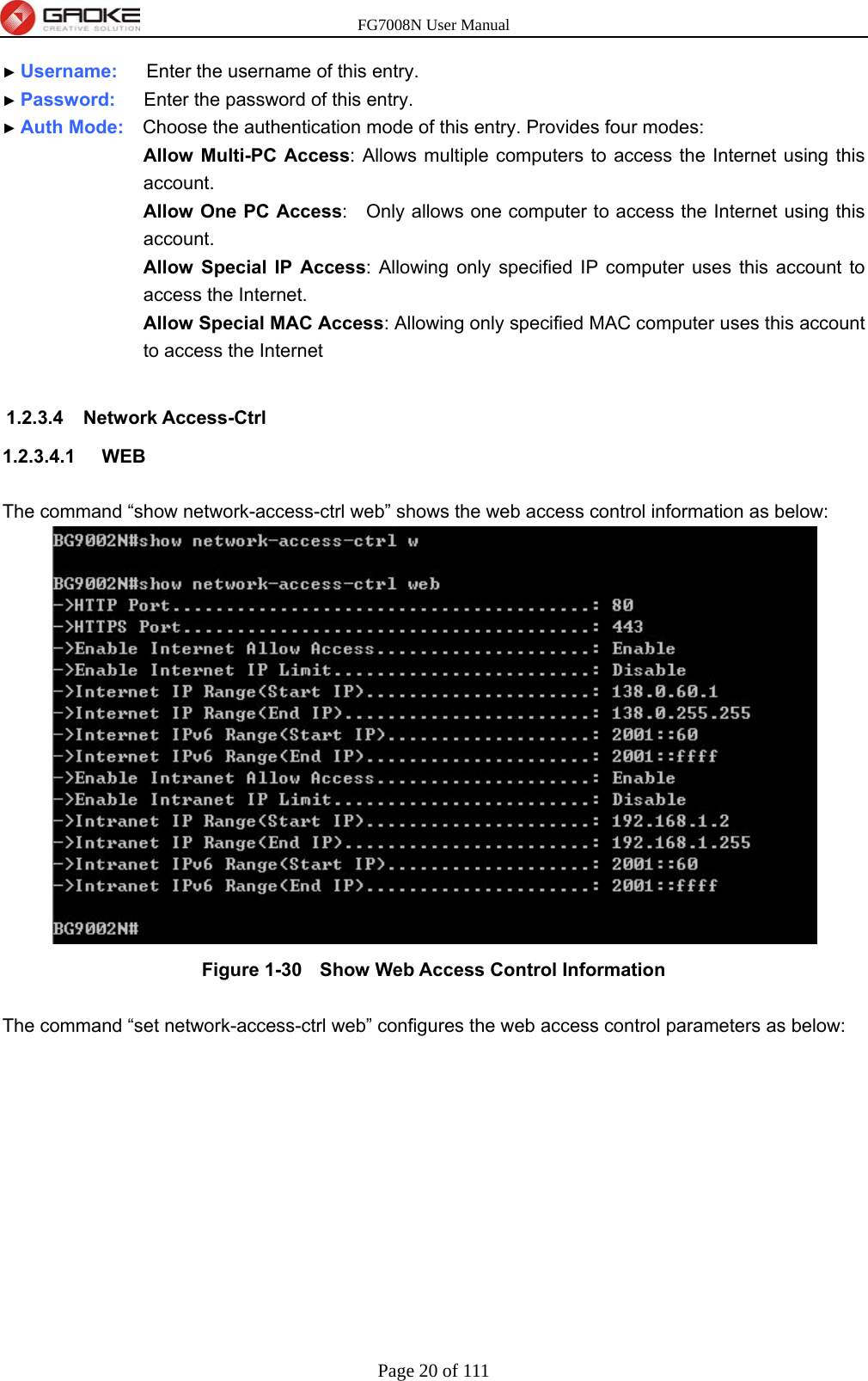
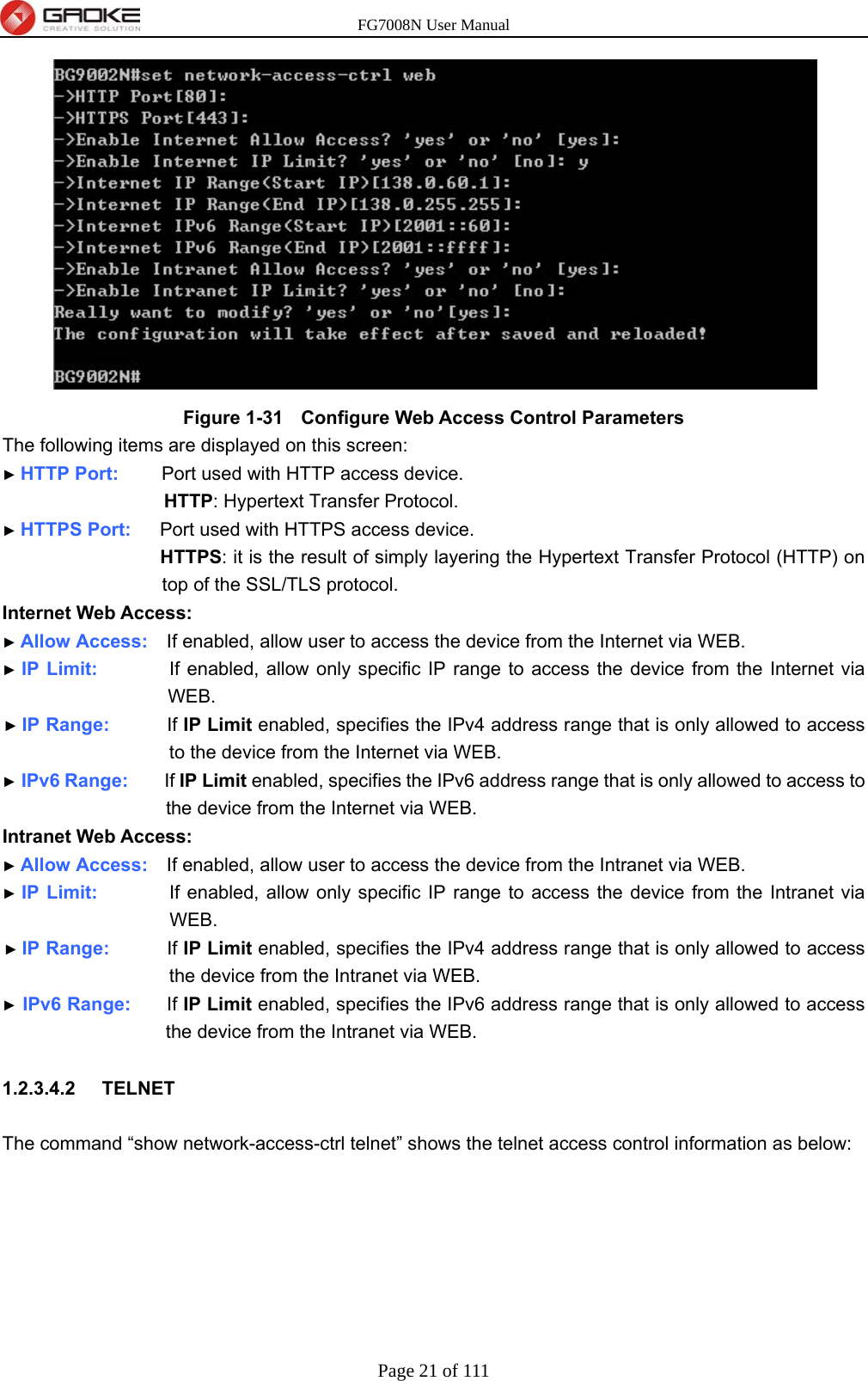
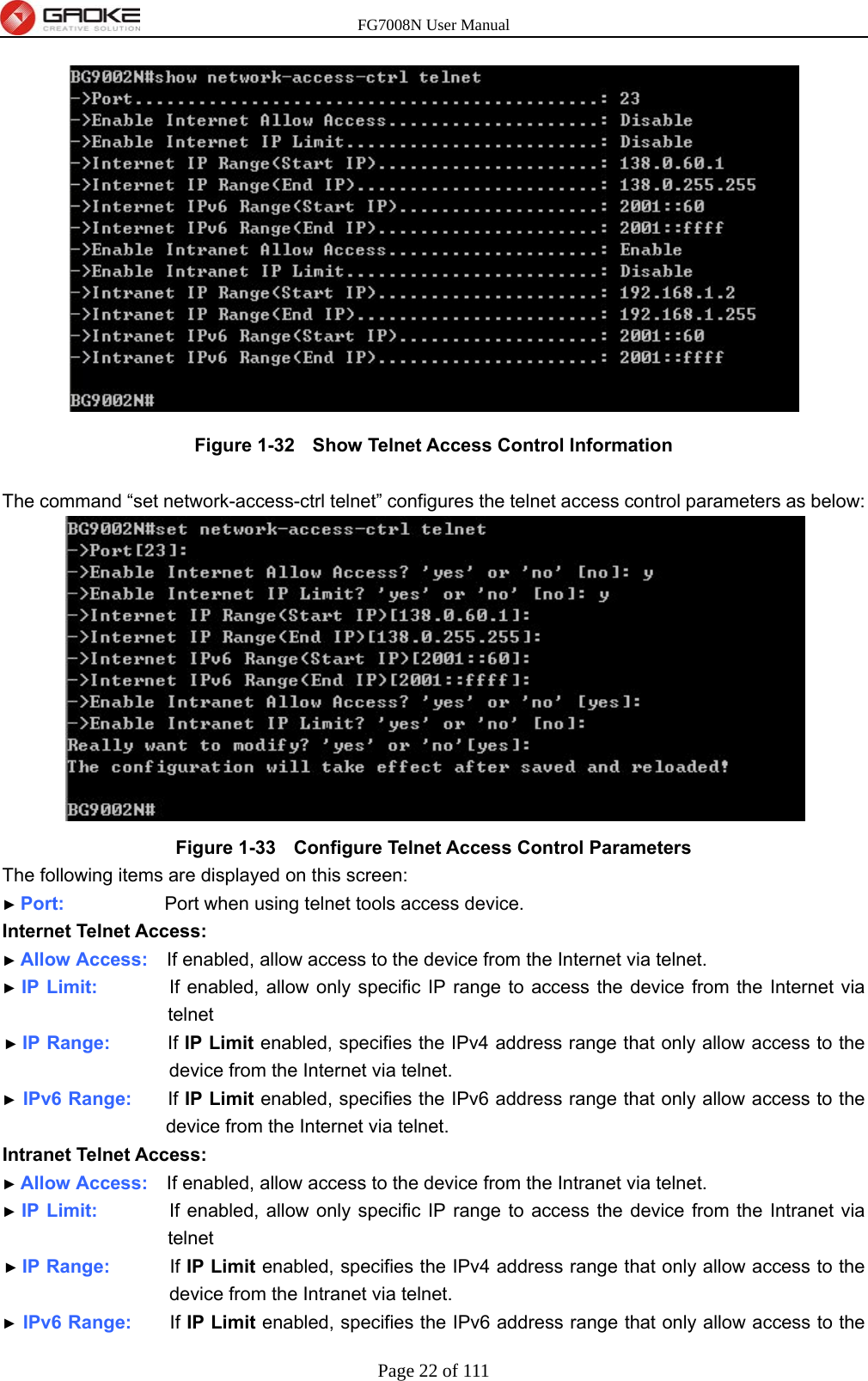
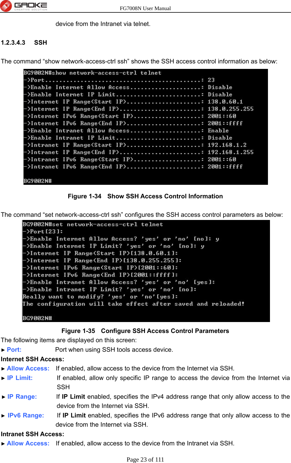
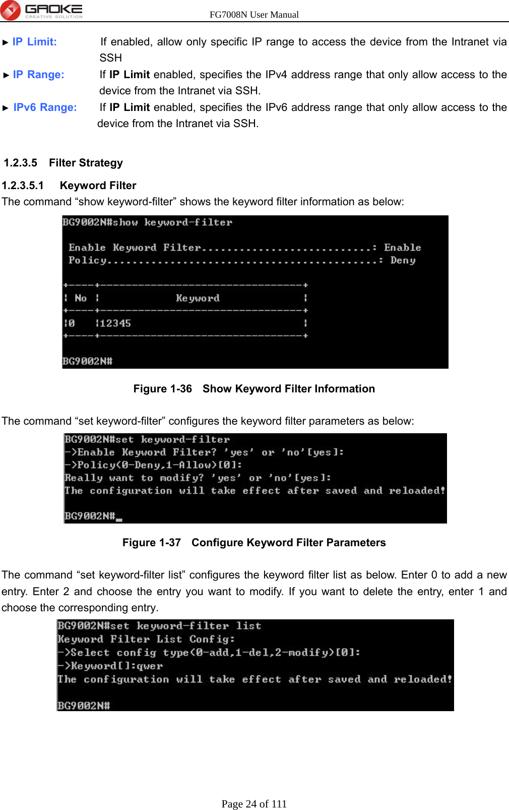
GUANGZHOU GAOKE COMMUNICATIONS TECHNOLOGY FG700X FIBER GATEWAY (Router) User Manual FG7008N USER S MANUAL2x

Guangzhou Gaoke Communications Technology Co., Ltd FIBER GATEWAY (Router) FG7008N USER S MANUAL2x

Contents

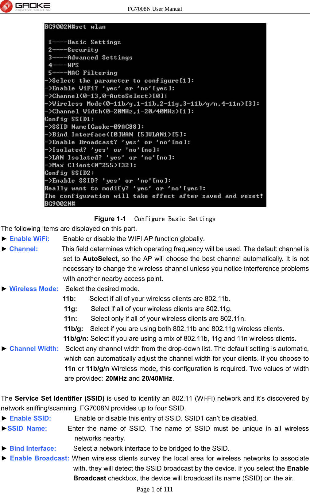
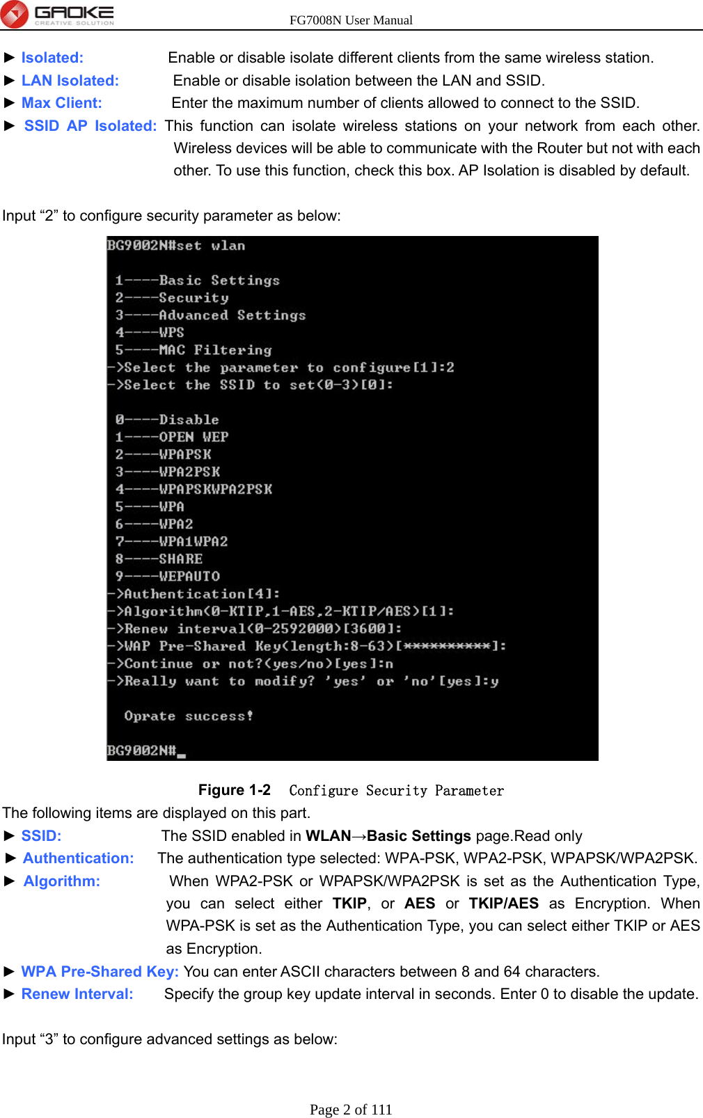
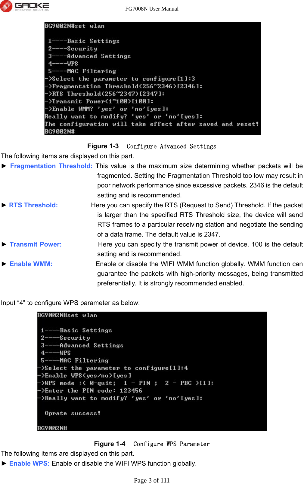
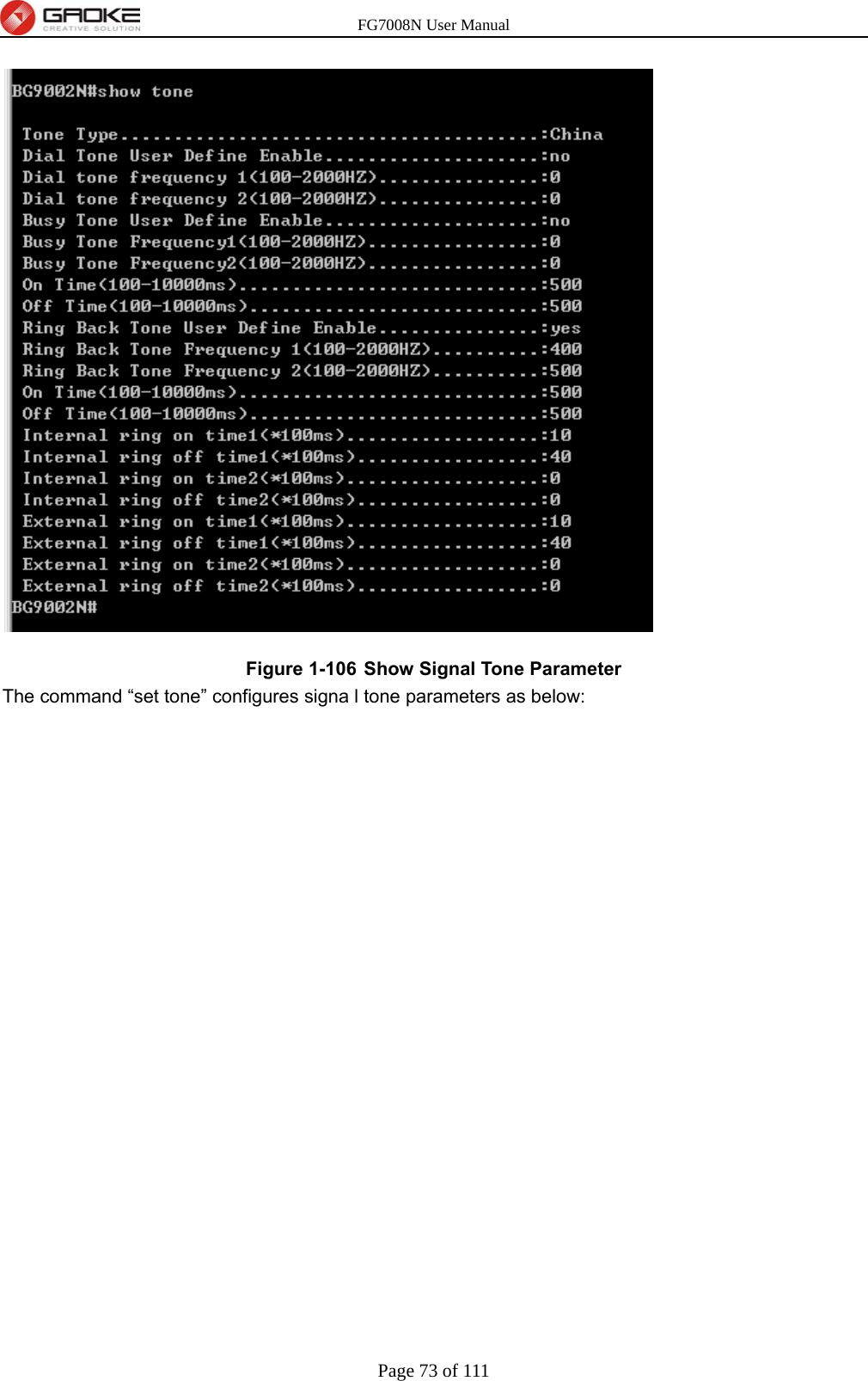
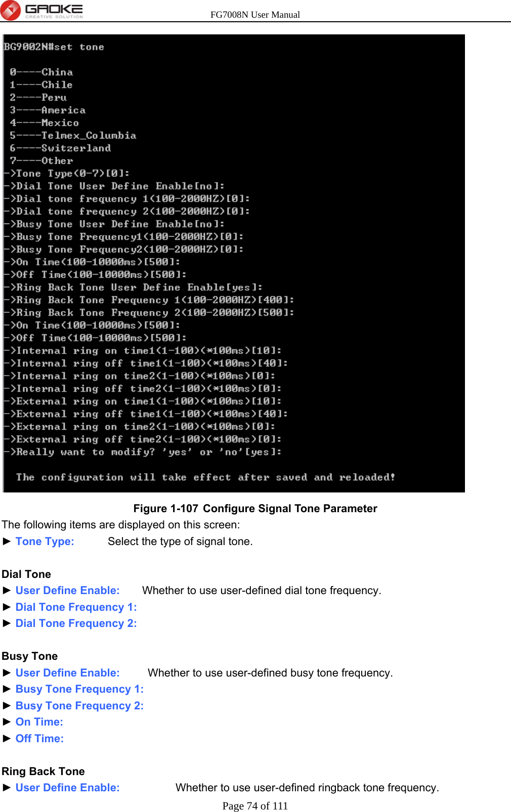
FG7008N User Manual-Part 2

FG7008N User Manual Page 1 of 111   Figure 1-1  Configure Basic Settings The following items are displayed on this part. ► Enable WiFi:    Enable or disable the WIFI AP function globally. ► Channel:       This field determines which operating frequency will be used. The default channel is set to AutoSelect, so the AP will choose the best channel automatically. It is not necessary to change the wireless channel unless you notice interference problems with another nearby access point. ► Wireless Mode:    Select the desired mode.   11b:    Select if all of your wireless clients are 802.11b.   11g:    Select if all of your wireless clients are 802.11g.   11n:        Select only if all of your wireless clients are 802.11n.   11b/g:    Select if you are using both 802.11b and 802.11g wireless clients.   11b/g/n: Select if you are using a mix of 802.11b, 11g and 11n wireless clients. ► Channel Width:    Select any channel width from the drop-down list. The default setting is automatic, which can automatically adjust the channel width for your clients. If you choose to 11n or 11b/g/n Wireless mode, this configuration is required. Two values of width are provided: 20MHz and 20/40MHz.  The Service Set Identifier (SSID) is used to identify an 802.11 (Wi-Fi) network and it’s discovered by network sniffing/scanning. FG7008N provides up to four SSID. ► Enable SSID:       Enable or disable this entry of SSID. SSID1 can’t be disabled. ►SSID Name:      Enter the name of SSID. The name of SSID must be unique in all wireless networks nearby. ► Bind Interface:     Select a network interface to be bridged to the SSID. ► Enable Broadcast: When wireless clients survey the local area for wireless networks to associate with, they will detect the SSID broadcast by the device. If you select the Enable Broadcast checkbox, the device will broadcast its name (SSID) on the air.
FG7008N User Manual Page 2 of 111  ► Isolated:           Enable or disable isolate different clients from the same wireless station. ► LAN Isolated:       Enable or disable isolation between the LAN and SSID. ► Max Client:         Enter the maximum number of clients allowed to connect to the SSID. ► SSID AP Isolated: This function can isolate wireless stations on your network from each other. Wireless devices will be able to communicate with the Router but not with each other. To use this function, check this box. AP Isolation is disabled by default.  Input “2” to configure security parameter as below:  Figure 1-2  Configure Security Parameter The following items are displayed on this part. ► SSID:             The SSID enabled in WLAN→Basic Settings page.Read only ► Authentication:   The authentication type selected: WPA-PSK, WPA2-PSK, WPAPSK/WPA2PSK. ► Algorithm:         When WPA2-PSK or WPAPSK/WPA2PSK is set as the Authentication Type, you can select either TKIP, or AES or TKIP/AES as Encryption. When WPA-PSK is set as the Authentication Type, you can select either TKIP or AES as Encryption. ► WPA Pre-Shared Key: You can enter ASCII characters between 8 and 64 characters. ► Renew Interval:    Specify the group key update interval in seconds. Enter 0 to disable the update.  Input “3” to configure advanced settings as below:
FG7008N User Manual Page 3 of 111   Figure 1-3  Configure Advanced Settings The following items are displayed on this part. ► Fragmentation Threshold: This value is the maximum size determining whether packets will be fragmented. Setting the Fragmentation Threshold too low may result in poor network performance since excessive packets. 2346 is the default setting and is recommended. ► RTS Threshold:          Here you can specify the RTS (Request to Send) Threshold. If the packet is larger than the specified RTS Threshold size, the device will send RTS frames to a particular receiving station and negotiate the sending of a data frame. The default value is 2347. ► Transmit Power:           Here you can specify the transmit power of device. 100 is the default setting and is recommended. ► Enable WMM:             Enable or disable the WIFI WMM function globally. WMM function can guarantee the packets with high-priority messages, being transmitted preferentially. It is strongly recommended enabled.  Input “4” to configure WPS parameter as below:  Figure 1-4  Configure WPS Parameter The following items are displayed on this part. ► Enable WPS: Enable or disable the WIFI WPS function globally.
FG7008N User Manual Page 4 of 111   Input “4” to configure MAC filtering parameter as below:
FG7008N User Manual Page 5 of 111   Figure 1-5  Configure MAC Filtering Parameter The following items are displayed on this part. ► Enable MAC Filter:        Enable or disable the Wifi MAC filtering function globally. ► Filtering Rules:   Two MAC filtering rules are provided: Allow: allow the stations specified by entries in the list to access. Deny: deny the stations specified by entries in the list to access. 1.2 Data Service  1.2.1 DHCP Server 1.2.1.1  Static Address Assign The command “show dhcp-server static-ip-assign” shows the static IP assign information as bellow:  Figure 1-6   Show Static IP Assign Information The command “set dhcp-server static-ip-assign” configures the static IP assign information as below.
FG7008N User Manual Page 6 of 111  Enter 0 to add a new entry. Enter 2 and choose the entry you want to modify. If you want to delete the entry, enter 1 and choose the corresponding entry.  Figure 1-7   Configure Static IP Assign   The command will configure static ip assign. The following items are displayed on this screen: ► IP :        The IP address reserved.
FG7008N User Manual Page 7 of 111  ► Mask:     The subnet mask of IP address reserved. ► MAC:     The MAC address you want to reserve IP address.  1.2.1.2 DHCP Relay  The command “show dhcp-relay” shows the DHCP relay information as below:  Figure 1-8   Show DHCP Relay Information The command "set dhcp-relay” configures the DHCP relay information as below:  Figure 1-9   Set DHCP Relay Information  The following items are displayed on this screen: ► Enable DHCP Relay: Enable or disable DHCP Relay. ► Client Interface:   The interface to listen for DHCP client requests. Up to four interfaces can be selected. ► Server Interface:    Choose the interface which connects DHCP server. ► Server IP:          Configure the DHCP server IP address.  1.2.2 NAT Config 1.2.2.1 Basic Settings  The command “show nat” shows the NAT basic settings as below:
FG7008N User Manual Page 8 of 111   Figure 1-10   Show NAT Basic Settings  The command “set nat” configures the NAT basic settings as below:  Figure 1-11   Configure NAT Basic Settings The following items are displayed on this screen: ► Max Nat Connections:      Specify the maximum number of NAT connections. ► Enable MSS Auto Adaptive: Enable or disable auto adaptive the value of MSS (Maximum Segment Size). ► TCP MSS:                 If Enable MSS Auto Adaptive is not selected, configure this to specify the maximum segment size of the TCP protocol.  1.2.2.2 PAT Settings  The command “show pat” shows the PAT information as below:  Figure 1-12   Show PAT Information  The command “set pat” configures the PAT parameters as below:
FG7008N User Manual Page 9 of 111   Figure 1-13   Configure PAT Parameters The following items are displayed on this screen: ► Enable PAT: Enable or disable PAT globally.  The command “set pat rule” configures the PAT rule as below. Enter 0 to add a new entry. Enter 2 and choose the entry you want to modify .If you want to delete the entry, enter 1 and choose the corresponding entry.
FG7008N User Manual Page 10 of 111   Figure 1-14   Configure PAT Rule The following items are displayed on this screen: ► Enable:           Enable or disable this PAT entry. ► Internet Port:      Enter the service port provided for accessing external network. All the requests from internet to this service port will be redirected to the specified server in local network. ► Intranet Port:      Specify the service port of the LAN host as virtual server. ► Intranet IP:        Enter the IP address of the specified internal server for the entry. All the requests from the internet to the specified LAN port will be redirected to this host. ► Protocol:          Specify the protocol used for the entry. ► Internet Interface:    Specify the interface to receive requests from the internet for the entry.  1.2.2.3 DMZ Settings  The command “show dmz” shows the DMZ information as below:  Figure 1-15   Show DMZ Information  The command “set dmz ” configures the DMZ Parameters as below:
FG7008N User Manual Page 11 of 111   Figure 1-16   Configure DMZ Parameters The following items are displayed on this screen: ► Enable DMZ: Enable or disable DMZ globally.  The command “set dmz rule” configures the DMZ rule as below. Enter 0 to add a new entry. Enter 2 and choose the entry you want to modify. If you want to delete the entry, enter 1 and choose the corresponding entry.  Figure 1-17   Configure DMZ Rule The following items are displayed on this screen:
FG7008N User Manual Page 12 of 111  ► Public IP:    The public IP address for this DMZ entry. ► Private IP:    The private IP address for this DMZ entry.  1.2.2.4 ALG Settings  The command “show alg” shows the ALG information as below:  Figure 1-18   Show ALG Information  The command “set alg” configures the ALG parameters as below:  Figure 1-19   Configure ALG Parameters The following items are displayed on this screen: ► Enable SIP:    Enable or disable SIP ALG. ► Enable H323:    Allow Microsoft NetMeeting clients to communicate across NAT if selected. ► Enable FTP:   Allow FTP clients and servers to transfer data across NAT if selected. ► Enable PPTP:    Enable or disable PPTP ALG. ► Enable RTSP:    Enable or disable RTSP ALG.  1.2.3 Firewall Config 1.2.3.1 Attack Defense  The command “show attack-defense” shows the attack defense information as below:
FG7008N User Manual Page 13 of 111   Figure 1-20   Show Attack Defense Information  The command “set attack-defense” configures the attack defense parameters as below:  Figure 1-21   Configure Attack Defense Parameters The following items are displayed on this screen: ► Enable Broadcast Storm Defense:    Enable or disable Broadcast Storm Defense. ► Enable Block Ping:            Enable or disable Block Ping function.   ► Enable TCP SYN Flood Defense:      Enable or disable TCP SYN Flood Defense. ► Enable UDP Flood Defense:        Enable or disable UDP Flood Defense. ► Enable ICMP Defense:          Enable or disable ICMP Defense. ► Enable ARP Attack Defense:        Enable or disable ARP Attack Defense. ► Enable Port Scan Defense:      A port scanner is a software application designed to probe a server or host for open ports. Check the box to prevent port scanning. ► Enable Land Based Defense:      The Land Denial of Service attack works by sending a spoofed packet with the SYN flag - used in a "handshake" between a client and a host - set from a host to any port that is open and
FG7008N User Manual Page 14 of 111  listening. If the packet is programmed to have the same destination and source IP address, when it is sent to a machine, via IP spoofing, the transmission can fool the machine into thinking it is sending itself a message, which, depending on the operating system, will crash the machine. Check the box to enable Land Based Defense. ► Enable Ping Of Death Defense:      Ping of death is a denial of service (DoS) attack caused by an attacker deliberately sending an IP packet larger than the 65,536 bytes allowed by the IP protocol. Check the box to enable Ping of Death Defense. ► Enable Teardrop Defense:       Teardrop is a program that sends IP fragments to a machine connected to the Internet or a network. Check the box to enable Teardrop Defense. ► Enable Fraggle Defense:      A fraggle attack is a variation of a Smurf attack where an attacker sends a large amount of UDP traffic to ports 7 (echo) and 19 (chargen) to an IP Broadcast Address, with the intended victim's spoofed source IP address. Check the box to enable Fraggle Defense. ► Enable Smurf Defense:          The Smurf Attack is a denial-of-service attack in which large numbers of Internet Control Message Protocol (ICMP) packets with the intended victim's spoofed source IP are broadcast to a computer network using an IP Broadcast address. Check the box to enable Smurf Defense.  1.2.3.2 Service Type  The command “show service-type” shows the service type information as below:  Figure 1-22   Show Service Type Information  The command “set service-type” configures the service type as below. Enter 0 add a new entry. Enter 2 and choose the entry you want to modify. If you want to delete the entry, enter 1 and choose the corresponding entry.
FG7008N User Manual Page 15 of 111   Figure 1-23   Configure Service Type The following items are displayed on this screen: ► Name:       Name of this entry, it will be list in Internet Access-Ctrl page. ► Protocol:    Select the protocol for this entry. Four types are provided: TCP, UDP, ICMP and ALL. ► Port Range:    Configure the port range for this entry.  1.2.3.3 Internet Access-Ctrl 1.2.3.3.1  Access Control
FG7008N User Manual Page 16 of 111  The command “show access-control” shows the access control information as below:  Figure 1-24   Show Access Control Information  The command “set access-control” configures the access control policy as below:  Figure 1-25   Configure Access Control  The following items are displayed on this screen: ► Enable Access Control: Enable or disable access control from WAN. ► Policy:               Default policy of access control: Allow or Deny. If Allow is selected, all packets will be allowed except the entries list on this page. If Deny is selected, all packets will be denied except the entries list on this page.  The command “set access-control rule” configures the access control rule as below. Enter 0 to add a new entry. Enter 2 and choose the entry you want to modify. If you want to delete the entry, enter 1 and choose the corresponding entry.
FG7008N User Manual Page 17 of 111
FG7008N User Manual Page 18 of 111   Figure 1-26   Configure Access Control Rule The following items are displayed on this screen: ► Enable Rule:         Enable or disable this rule. ► Source IP Range:     Enter the source IP range in dotted-decimal format (e.g. 192.168.1.23). ► Destination IP Range: Enter the destination IP range in dotted-decimal format (e.g. 192.168.1.23). ► Service Name:       Choose a service type that defined in Service Type page. ► Active Time:         Specify the time range for the entry to take effect. ► Active Day:          Specify the day range for the entry to take effect.  1.2.3.3.2  User Authentication  The command “show user-authentication” shows the user authentication information as below:  Figure 1-27   Show User Authentication Information  The command “set user-authentication” configures the user authentication parameters as below:  Figure 1-28   Configure User Authentication Parameters The following items are displayed on this screen: ► Enable User Authentication:   Enable or disable user authentication globally. If enabled, only the following list of users and passwords can access the Internet.
FG7008N User Manual Page 19 of 111   The command “set user authentication list” configures the user authentication list as below. Enter 0 to add a new entry. Enter 2 and choose the entry you want to modify. If you want to delete the entry, enter 1 and choose the corresponding entry.  Figure 1-29   Configure User Authentication List The following items are displayed on this screen:
FG7008N User Manual Page 20 of 111  ► Username:    Enter the username of this entry. ► Password:   Enter the password of this entry. ► Auth Mode:    Choose the authentication mode of this entry. Provides four modes:  Allow Multi-PC Access: Allows multiple computers to access the Internet using this account.  Allow One PC Access:    Only allows one computer to access the Internet using this account. Allow Special IP Access: Allowing only specified IP computer uses this account to access the Internet. Allow Special MAC Access: Allowing only specified MAC computer uses this account to access the Internet  1.2.3.4 Network Access-Ctrl 1.2.3.4.1  WEB  The command “show network-access-ctrl web” shows the web access control information as below:  Figure 1-30   Show Web Access Control Information  The command “set network-access-ctrl web” configures the web access control parameters as below:
FG7008N User Manual Page 21 of 111   Figure 1-31   Configure Web Access Control Parameters The following items are displayed on this screen: ► HTTP Port:      Port used with HTTP access device. HTTP: Hypertext Transfer Protocol. ► HTTPS Port:    Port used with HTTPS access device. HTTPS: it is the result of simply layering the Hypertext Transfer Protocol (HTTP) on top of the SSL/TLS protocol. Internet Web Access: ► Allow Access:    If enabled, allow user to access the device from the Internet via WEB. ► IP Limit:          If enabled, allow only specific IP range to access the device from the Internet via WEB. ► IP Range:        If IP Limit enabled, specifies the IPv4 address range that is only allowed to access to the device from the Internet via WEB. ► IPv6 Range:     If IP Limit enabled, specifies the IPv6 address range that is only allowed to access to the device from the Internet via WEB. Intranet Web Access: ► Allow Access:    If enabled, allow user to access the device from the Intranet via WEB. ► IP Limit:          If enabled, allow only specific IP range to access the device from the Intranet via WEB. ► IP Range:        If IP Limit enabled, specifies the IPv4 address range that is only allowed to access the device from the Intranet via WEB. ► IPv6 Range:     If IP Limit enabled, specifies the IPv6 address range that is only allowed to access the device from the Intranet via WEB.  1.2.3.4.2  TELNET  The command “show network-access-ctrl telnet” shows the telnet access control information as below:
FG7008N User Manual Page 22 of 111   Figure 1-32   Show Telnet Access Control Information  The command “set network-access-ctrl telnet” configures the telnet access control parameters as below:  Figure 1-33   Configure Telnet Access Control Parameters The following items are displayed on this screen: ► Port:              Port when using telnet tools access device. Internet Telnet Access: ► Allow Access:    If enabled, allow access to the device from the Internet via telnet. ► IP Limit:          If enabled, allow only specific IP range to access the device from the Internet via telnet ► IP Range:        If IP Limit enabled, specifies the IPv4 address range that only allow access to the device from the Internet via telnet. ► IPv6 Range:     If IP Limit enabled, specifies the IPv6 address range that only allow access to the device from the Internet via telnet. Intranet Telnet Access: ► Allow Access:    If enabled, allow access to the device from the Intranet via telnet. ► IP Limit:          If enabled, allow only specific IP range to access the device from the Intranet via telnet ► IP Range:        If IP Limit enabled, specifies the IPv4 address range that only allow access to the device from the Intranet via telnet. ► IPv6 Range:     If IP Limit enabled, specifies the IPv6 address range that only allow access to the
FG7008N User Manual Page 23 of 111  device from the Intranet via telnet.  1.2.3.4.3  SSH  The command “show network-access-ctrl ssh” shows the SSH access control information as below:  Figure 1-34   Show SSH Access Control Information  The command “set network-access-ctrl ssh” configures the SSH access control parameters as below:  Figure 1-35   Configure SSH Access Control Parameters The following items are displayed on this screen: ► Port:              Port when using SSH tools access device. Internet SSH Access: ► Allow Access:    If enabled, allow access to the device from the Internet via SSH. ► IP Limit:          If enabled, allow only specific IP range to access the device from the Internet via SSH ► IP Range:        If IP Limit enabled, specifies the IPv4 address range that only allow access to the device from the Internet via SSH. ► IPv6 Range:     If IP Limit enabled, specifies the IPv6 address range that only allow access to the device from the Internet via SSH. Intranet SSH Access: ► Allow Access:    If enabled, allow access to the device from the Intranet via SSH.
FG7008N User Manual Page 24 of 111  ► IP Limit:           If enabled, allow only specific IP range to access the device from the Intranet via SSH ► IP Range:        If IP Limit enabled, specifies the IPv4 address range that only allow access to the device from the Intranet via SSH. ► IPv6 Range:     If IP Limit enabled, specifies the IPv6 address range that only allow access to the device from the Intranet via SSH.  1.2.3.5 Filter Strategy 1.2.3.5.1  Keyword Filter The command “show keyword-filter” shows the keyword filter information as below:  Figure 1-36   Show Keyword Filter Information  The command “set keyword-filter” configures the keyword filter parameters as below:  Figure 1-37   Configure Keyword Filter Parameters  The command “set keyword-filter list” configures the keyword filter list as below. Enter 0 to add a new entry. Enter 2 and choose the entry you want to modify. If you want to delete the entry, enter 1 and choose the corresponding entry.
FG7008N User Manual Page 25 of 111   Figure 1-38   Configure Keyword Filter List The following items are displayed on this screen: ► Keyword Filter:  If enabled, packet filtering is enabled by keyword. ► Policy:         The policy for filtering web page, Deny and Allow.  1.2.3.5.2  IP Filter The command “show ip-filter” shows the IP filter information as below:  Figure 1-39   Show IP Filter Information  The command “set ip-filter” configures the IP filter parameters as below:
FG7008N User Manual Page 26 of 111   Figure 1-40   Configure IP Filter Parameters  The command “set ip-filter list” configures the IP filter list as below. Enter 0 to add a new entry. Enter 2 and choose the entry you want to modify. If you want to delete the entry, enter 1 and choose the corresponding entry.  Figure 1-41   Configure IP Filter List The following items are displayed on this screen: ► IP Filter:    If enabled, packet filtering is enabled by IP address. ► Policy:    The policy for IP address list. Deny and Allow.
FG7008N User Manual Page 27 of 111   1.2.3.5.3  MAC Filter The command “show mac-filter” shows the MAC filter information as below:  Figure 1-42   Show MAC Filter Information  The command “set mac-filter ” configures the MAC filter parameters as below:  Figure 1-43   Configure IP Filter Parameters  The command “set mac-filter list” configures the MAC filter list as below. Enter 0 to add a new entry. Enter 2 and choose the entry you want to modify. If you want to delete the entry, enter 1 and choose the corresponding entry.
FG7008N User Manual Page 28 of 111   Figure 1-44   Configure MAC Filter List The following items are displayed on this screen: ► MAC Filter:   If enabled, packet filtering is enabled by MAC. ► Policy:      The policy for MAC list. Deny and Allow.  1.2.4 QoS 1.2.4.1 Basic Settings The command “show qos basic-settings” shows the QoS basic settings as below:  Figure 1-45   Show QoS Basic Settings  The command “set qos basic-settings” configures the QoS basic settings as below:
FG7008N User Manual Page 29 of 111   Figure 1-46   Configure QoS Basic Settings The following items are displayed on this screen: ► Qos Enable:                  Enable or disable QoS functionality. ► Scheduling Mode:        PQ:  PQ means strict priority, that is, when congestion occurs, first sending packets of high priority queue. WRR: All queues use weighted fair queuing scheme which is defined in Weight Ratio PQ+WRR: Only highest queue use strict priority; others use weighted fair queuing scheme. ► Qos Priority:            DSCP  and 802.1P: depending on the value of priority classification into different queues. ► Upstream Bandwidth:       Configure the bandwidth of upstream. ► Downstream Bandwidth:    Configure the bandwidth of downstream. ► Enable Voice Reservation:      Enable voice reservation and give the value to reserved for voice ► Enable Video Reservation:      Enable video reservation and give the value to reserved for video ► Remap Tos/DSCP to CoS:   Check the box that the system will remark 802.1P value with TOS/DSCP of upstream packets, the mapping relationship is as follows: 1.2.4.2  Port Rate Limit The command “show qos port-limit” shows the port rate limit information as below:
FG7008N User Manual Page 30 of 111   Figure 1-47   Show Port Rate Limit Information  The command “set qos port-limit” configures the port rate limit as below:  Figure 1-48   Configure Port Rate Limit The following items are displayed on this screen: ► Port:           Physical LAN port ► Enable:         Enable or disable rate limit function. ► Incoming Rate Limit:    Enter incoming maximum rate, which must is times of 32Kbsp. ►Limit Packet Type:      Select the packet type which is limited rate. ► Outgoing Rate Limit:    Enter Outgoing maximum rate, which must is times of 32Kbsp.  1.2.4.3  Flow Rate Limit The command “show qos flow-limit” shows the flow rate limit information as below:
FG7008N User Manual Page 31 of 111   Figure 1-49   Show Flow Rate Limit Information  The command “set qos flow-limit” configures the flow rate limit as below. Enter 0 add a new entry. Enter 2 and choose the entry you want to modify. If you want to delete the entry, enter 1 and choose the corresponding entry.
FG7008N User Manual Page 32 of 111   Figure 1-50   Configure Flow Rate Limit The following items are displayed on this screen: ► IP Range:                     The IP range of LAN’s PC. ► Active Time:                  If not configured, which means that all time are in active ► Active Day:                   If not configured, which means that all time in active ► Direction:                      Up: Check the frame from the direction of the LAN port to the WAN port, and match the source IP and destination port; Down: Check the frame from the direction of the WAN port to the LAN port, and match the destination IP and source port;
FG7008N User Manual Page 33 of 111  Bidirectional: Limit both upstream and downstream speed. ► Limited Bandwidth(CIR):    The limited bandwidth. ► Maximal Bandwidth(PIR):   The maximum bandwidth.  If Application is selected: ► Application Protocol:     Such as HTTP, HTTPS, FTP, TFTP, SMTP, POP3, TELNET, etc.  1.2.4.4 Service The command “show qos service” shows the QoS service information as below:  Figure 1-51   Show QoS Service Information  The command “set qos service” configures the QoS service as below:  Figure 1-52   Configure QoS Service The following items are displayed on this screen: ► Name:                Service name. Read only. ► Remap Queue Priority: Check the box to remap scheduling queue.
FG7008N User Manual Page 34 of 111  ► Priority:              There are four levels of priority. Priority 3 is highest, and priority 0 is the lowest ► Remark 802.1p:       Check the box to enable 802.1p priority remarking. ► 802.1p Value:         The value of remarking 802.1P. ► Remark DSCP:        Check the box to enable DSCP remarking. ► DSCP Value:          The value of remarking DSCP.  1.2.4.5 ACL  The command “show qos acl-rule” shows the ACL rule information as below:  Figure 1-53   Show ACL Rule Information  The command “set qos acl-rule” configures the ACL rule as below:  Figure 1-54   Configure ACL Rule
FG7008N User Manual Page 35 of 111  The following items are displayed on this screen: ► Rule Name:     The custom name. ► Physical Port:   Rule’s source port ► Rule Type:      Type of rule: L2 data or L3 data. ► Src IP/Netmask:  The source IP address and netmask of packets, such as 192.168.100.1/255.255.255.0. ► Dest IP/Netmask: The destination IP address and netmask of packets. ► Protocol:        E.g. ICMP, UDP, TCP, or custom IP protocol types. ► SRC MAC:        Source MAC address of packets. ► DEST MAC:       Destination MAC address of packets. ► Ether Type:       The ether type of packets. ► VLAN ID:         The VLAN id of packets. ► 802.1p:           The VLAN priority of packets. ► Drop:                Drop the packets matched with the rule. ► Remark VID:        Change the VID of packets matched with the rule. ► Remark 802.1p:     Change the 802.1P priority of packets matched with the rule. ► Remark DSCP:       Change the DSCP of packets matched with the rule. ► Priority:            Change the scheduling queue of packets matched with the rule. ► Maximal Bandwidth: Limit the bandwidth of packet matched with the rule.  1.2.5 DDNS The command “show ddns status” shows the DDNS status as below:  Figure 1-55   Show DDNS Status The command “show ddns parameter” shows the DDNS parameters as below:  Figure 1-56   Show DDNS Parameters  The command "set ddns” configures the DDNS parameters as below:
FG7008N User Manual Page 36 of 111   Figure 1-57   Configure DDNS Parameters  The following items are displayed on this screen: ► DDNS Enable:          Active or inactive dynamic DNS service. ► Username:             Enter account name of your DDNS account. ► Password:             Enter password of your DDNS account. ► First Url:                              First domain name that you registered your DDNS service provider. ► Second Url:                        First domain name that you registered your DDNS service provider. ► Update Interval:        How often, in seconds, the IP is updated. ► Server Type:                      optional DDNS server type, can select from pull-dwon list: DYNDNS:  For dyndns.org FREEDNS: For freedns.afraid.org ZONE: For zoneedit.com   NOIP: For no-ip.com 3322: For 3322.org CUSTOM: For custom self-defined DDNS server type. ► Server Name:          If CUSTOM is selected, specify server name of the device. ► Server Url:             If CUSTOM is selected, specify server URL of the device. ► Dyn DNS Server Name: If CUSTOM is selected, specify dyndns DNS server name of custom self-defined. ► Dyn DNS Server Url:  If CUSTOM is selected, specify dyndns DNS server URL of custom self-defined. ► System Item:          If CUSTOM is selected, specify system item of custom self-defined. ► DDNS Status:          Display the status of DDNS service. Read only.  1.2.6 VPN 1.2.6.1 PPTP Server The command “show pptp-server” shows the pptp server information as below:
FG7008N User Manual Page 37 of 111   Figure 1-58   Show PPTP Server Information   The command “set pptp-server” configures the pptp server parameters as below:  Figure 1-59   Configure PPTP Server Parameters  The following items are displayed on this screen: ► Enable PPTP Server:     Enable or disable the PPTP server function globally. ► IP Address Pool Range: Specify the start and the end IP address for IP Pool. The start IP address should not exceed the end address and the IP ranges must not overlap. ► Enable Authentication:    Specify whether to enable authentication for the tunnel. ► Enable Encryption:     Specify whether to enable the encryption for the tunnel. If enabled, the PPTP tunnel will be encrypted by MPPE.  The command “set pptp-server user” configures the pptp server user list as below. Enter 0 to add a new entry. Enter 2 and choose the entry you want to modify. If you want to delete the entry, enter 1 and choose the corresponding entry.
FG7008N User Manual Page 38 of 111   Figure 1-60   Configure PPTP Server User The following items are displayed on this screen: ► Username:   Enter the account name of PPTP tunnel. It should be configured identically on server and client. ► Password:  Enter the password of PPTP tunnel. It should be configured identically on server and client. ► Binding IP:    Enter the IP address of the client which is allowed to connect to this PPTP server.  1.2.6.2 L2TP Server The command “show l2tp-server” shows the l2tp server information as below:  Figure 1-61   Show L2TP Server Information  The command “set l2tp-server” configures the l2tp server parameters as below:
FG7008N User Manual Page 39 of 111   Figure 1-62   Configure L2TP Server Parameters  The following items are displayed on this screen: ► Enable L2TP Server:     Enable or disable the L2TP server function globally. ► Local IP:                    Enter the local IP address of L2TP server. ► IP Address Pool Range: Specify the start and the end IP address for IP Pool. The start IP address should not exceed the end address and the IP ranges must not overlap. ► Enable Authentication:    Specify whether to enable authentication for the tunnel. If enabled, enter the authentication secret. ► Enable Debug:         Specify whether to enable the debug for L2TP.  The command “set l2tp-server user” configures the l2tp server user list as below. Enter 0 to add a new entry. Enter 2 and choose the entry you want to modify .If you want to delete the entry, enter 1 and choose the corresponding entry.
FG7008N User Manual Page 40 of 111   Figure 1-63   Configure L2TP Server User The following items are displayed on this screen: ► Username:   Enter the account name of L2TP tunnel. It should be configured identically on server and client. ► Password:  Enter the password of L2TP tunnel. It should be configured identically on server and client. ► Binding IP:    Enter the IP address of the client which is allowed to connect to this L2TP server.  1.2.6.3 IPSEC 1.2.6.3.1  IKE Safety Proposal The command “show ike-proposal” shows the IKE Proposal information as below:
FG7008N User Manual Page 41 of 111   Figure 1-64   Show IKE Proposal Information  The command “set ike-proposal” configures the IKE Proposal as below. Enter 0 to add a new entry. Enter 2 and choose the entry you want to modify. If you want to delete the entry, enter 1 and choose the corresponding entry.
FG7008N User Manual Page 42 of 111   Figure 1-65   Configure IKE Proposal The following items are displayed on this screen: ► Proposal Name:        Specify a unique name to the IKE proposal for identification and management purposes. The IKE proposal can be applied to IPSEC proposal. ► Encryption Algorithm:   Specify the encryption algorithm for IKE negotiation. Options include: DES: DES (Data Encryption Standard) encrypts a 64-bit block of plain text with a 56-bit key. 3DES: Triple DES, encrypts a plain text with 168-bit key. AES: Uses the AES algorithm for encryption. ► Auth Algorithm:         Select the authentication algorithm for IKE negotiation. Options include: MD5: MD5 (Message Digest Algorithm) takes a message of arbitrary length and generates a 128-bit message digest. SHA1: SHA1 (Secure Hash Algorithm) takes a message less than 2^64 (the 64th power of 2) in bits and generates a 160-bit message digest. ► DH Group:                Select the DH (Diffie-Hellman) group to be used in key negotiation phase 1. The DH Group sets the strength of the algorithm in bits. Options include DH 768 modp, DH 1024 modp and DH 1536 modp.   1.2.6.3.2  IKE Safety Policy The command “show ike-policy” shows the IKE Policy information as below:
FG7008N User Manual Page 43 of 111   Figure 1-66   Show IKE Policy Information  The command “set ike-policy” configures the IKE Policy as below. Enter 0 add a new entry. Enter 2 and choose the entry you want to modify. If you want to delete the entry, enter 1 and choose the corresponding entry.
FG7008N User Manual Page 44 of 111   Figure 1-67   Configure IKE Policy The following items are displayed on this screen: ► Policy Name:               Specify a unique name to the IKE policy for identification and management purposes. The IKE policy can be applied to IPSEC policy. ► Operation Mode:          Select the IKE Exchange Mode in phase 1, and ensure the remote VPN peer uses the same mode. Main: Main mode provides identity protection and exchanges more information, which applies to the scenarios with higher requirement for identity protection. Challenge: Challenge Mode establishes a faster connection but with lower security, which applies to scenarios with lower requirement for identity protection. ► Enable Local ID:           If enabled, enter a name for the local device as the ID in IKE negotiation.
FG7008N User Manual Page 45 of 111  ► Enable Remote ID:        If enabled, enter the name of the remote peer as the ID in IKE negotiation. ► Auth Mode:                 Select the authentication mode for this IKE policy entry. ► Pre Share Key:           Enter the Pre-shared Key for IKE authentication, and ensure both the two               peers use the same key. The key should consist of visible characters without         blank space. ► Enable Safety Proposal:  Select the Proposal for IKE negotiation phase 1. Up to four proposals can be selected.  1.2.6.3.3  IPSEC Safety Proposal The command “show ipsec-proposal” shows the IPSEC Proposal information as below:  Figure 1-68   Show IPSEC Proposal Information  The command “set ipsec-proposal” configures the IPSEC Proposal as below. Enter 0 add a new entry. Enter 2 and choose the entry you want to modify. If you want to delete the entry, enter 1 and choose the corresponding entry.
FG7008N User Manual Page 46 of 111   Figure 1-69   Configure IPSEC Proposal The following items are displayed on this screen: ► Proposal Name:       Specify a unique name to the IPSEC Proposal for identification and management purposes. The IPSEC proposal can be applied to IPSEC policy. ► IPSec Protocol:         Select the security protocol to be used. Options include: AH: AH (Authentication Header) provides data origin authentication, data integrity and anti-replay services. ESP: ESP (Encapsulating Security Payload) provides data encryption in addition to origin authentication, data integrity, and anti-replay services. ESP+AH: Both ESP and AH security protocol. ► Encryption Algorithm:    Select the algorithm used to encrypt the data for ESP encryption. Options include: DES: DES (Data Encryption Standard) encrypts a 64-bit block of plain text with a 56-bit key. The key should be 8 characters. 3DES: Triple DES, encrypts a plain text with 168-bit key. The key should be 24 characters. AES: Uses the AES algorithm for encryption. The key should be 16 characters.
FG7008N User Manual Page 47 of 111  ► Auth Algorithm:        Select the algorithm used to verify the integrity of the data. Options include: MD5: MD5 (Message Digest Algorithm) takes a message of arbitrary length and generates a 128-bit message digest. SHA: SHA (Secure Hash Algorithm) takes a message less than the 64th power of 2 in bits and generates a 160-bit message digest.  1.2.6.3.4  IPSEC Safety Policy The command “show ipsec-policy” shows the IPSEC Policy information as below:  Figure 1-70   Show IPSEC Policy Information  The command “set ipsec-policy” configures the IPSEC Policy as below. Enter 0 to add a new entry. Enter 2 and choose the entry you want to modify. If you want to delete the entry, enter 1 and choose the corresponding entry.
FG7008N User Manual Page 48 of 111
FG7008N User Manual Page 49 of 111   Figure 1-71   Configure IPSEC Policy The following items are displayed on this screen: ► Enable Ipsec:              Enable or disable this IPSEC entry. ► IPSEC Policy Name:    Specify a unique name to the IPSEC policy. ► Select Interface:        Specify the local WAN port for this Policy. ► VPN Mode:             Select the network mode for IPSEC policy. Options include: Site To Site: Select this option when the client is a network. PC to Site: Select this option when the client is a host. ► Local Subnet IP & Local Subnet Netmask: Specify IP address range on your local LAN to identify which PCs on your LAN are covered by this policy. ► Remote Address:      If PC to Site is selected, specify IP address on your remote network to identify which PCs on the remote network are covered by this policy. ► Remote Subnet IP & Remote Subnet Netmask: Specify IP address range on your remote network to identify which PCs on the remote network are covered by this policy. ► IKE Safety Policy:     Specify the IKE policy.   ► Enable Safety Prososal: If enabled, Select IPSEC Proposal.    1.2.7 Routing 1.2.7.1 Static Route 1.2.7.1.1  IPv4 The command “show static-route ipv4” shows the IPv4 static route information as below:  Figure 1-72   Show IPv4 Static Route Information
FG7008N User Manual Page 50 of 111  The command “set static-route ipv4” configures the IPv4 static route as below.    Figure 1-73   Configure IPv4 Static Route The following items are displayed on this screen: ► Enable:            Select it to add and modify the current route. Conversely, disable the current route. ► Destination IP:      Enter the destination host the route leads to. ► Netmask:            Enter the Subnet mask of the destination network. ► Next Hop Type:      Include Next Hop Interface and Next Hop Address(see following option) ► Next Hop Interface:  Specify the interface of next hop for current route ► Next Hop Address:    Specify the address of next hop for current route ► Valid:                Show the status of current route.  1.2.7.1.2  IPv6 The command “show static-route ipv6” show the IPv6 static route information as below:  Figure 1-74   Show IPv6 Static Route Information  The command “set static-route ipv6” configures the IPv6 static route as below.    Figure 1-75   Configure IPv6 Static Route The configuration options of Ipv6 is similar to Ipv4, the prefix length is equal to mask of Ipv4 address.
FG7008N User Manual Page 51 of 111   1.2.7.2 Policy Route The command “show policy-route” shows the policy route information as below:  Figure 1-76   Show Policy Route Information  The command “set policy-route” configure thes policy route as below. Enter 0 to add a new entry. Enter 2 and choose the entry you want to modify. If you want to delete the entry, enter 1 and choose the corresponding entry.
FG7008N User Manual Page 52 of 111
FG7008N User Manual Page 53 of 111   Figure 1-77   Configure Policy Route The following items are displayed on this screen: ► Enable PoliceRoute: Enable or disable the entry ► Next Hop Type:      Select from pull-down list: Interface, Address. ► Interface:           Specify the interface of next hop for the entry. ► Address:           Specify the address of next hop for the entry. ► Description:        Give description for the entry. ► Protocol:           Specify the protocol, TCP, UDP or ALL. ► Source IP:                    Enter IP address or IP range of source in the rule entry. ► Destination IP:           Enter IP address or IP range of destination in the rule entry. ► Destination Port:        Specify port or port range of destination in the rule entry. ► Active Time:        Specify the active time range for the rule entry. ► Active Day:                  Specify the active days for the rule entry.  1.2.7.3 RIP 1.2.7.3.1  RIP Service The command “show rip” shows the RIP information as below:  Figure 1-78   Show RIP Information  The command “set rip switch” configures the RIP switch as below:
FG7008N User Manual Page 54 of 111  Figure 1-79   Configure RIP Switch The following items are displayed on this page: ► Enable RIP Service: Enable or disable RIP service function globally.  The command “set rip interface” configures the RIP interface as below.
FG7008N User Manual Page 55 of 111   Figure 1-80   Configure RIP Interface The following items are displayed on this screen:  ► Interface:             Specify the interface for the entry. ► Receive RIP Version:  Specify receiving RIP version for the entry. ► Send RIP Version:     Specify sending RIP version for the entry. ► Authorization Enable:    Check the box to enable authorization. ► Key Mode:            Specify the encryption mode of key, TEXT(plaintext),MD5(cipertext). ► Key Type:             Specify the key from Simple String or Key Chain. ► Simple String:           If select Simple String in item of Key Type, enter simple string as key.  1.2.7.3.2  Key Chain The command “set rip key-chain” configures the RIP key chain as below.
FG7008N User Manual Page 56 of 111   Figure 1-81   Configure RIP Key Chain The following items are displayed on this screen: ► Key Chain Name: Enter the name of key chain. ► Key ID:      Enter the ID of the entry. ► Key String:    Enter the Key of the entry. 1.2.8 Advanced Parameters 1.2.8.1 UPnP Parameter The command “show upnp” shows the UPnP information as below:
FG7008N User Manual Page 57 of 111   Figure 1-82   Show UPnP Information  The command “set upnp” configures the UPnP parameters as below.    Figure 1-83   Configure UPnP Parameters The following items are displayed on this screen: ► Enable UPnP:             Enable or disable the UPnP function globally. ► Upstream Interface:        The network interface connected to the DLNA server. ► Downstream Interface: The network interface connected to the DLNA client.  1.2.9 Multicast The command “show multicast” shows the multicast information as below:  Figure 1-84   Show Multicast Information  The command “set multicast” configures the multicast parameters as below.    Figure 1-85   Configure Multicast Parameters The following items are displayed on this screen: ► Enable IGMP Proxy:  Enable or disable the IGMP proxy function globally. Currently, IGMP proxy is mainly used for IPTV.
FG7008N User Manual Page 58 of 111  1.3 VOIP Service  1.3.1 SIP Service The command “show sip” shows the sip service information as bellow:  Figure 1-86   Show Sip Server Information  Execute the command “set sip” to set the sip information as below:
FG7008N User Manual Page 59 of 111   Figure 1-87   Configure Sip Server   At first, the command will show the sip server information, and then begin to configure sip server. The following items are displayed on this screen: ► Register server ip or domain:    Domain or IP of SIP server. ► Register Server Port:      Listening port of SIP server. ► Enable Backup Server or not:      Enable or disable backup SIP server. ► Backup Server IP or Domain:    Domain or IP of backup SIP server. ► Backup Register Server Port:      Listening port of backup SIP server. ► Enable Proxy Server or not:          Enable or disable Proxy server. ► Proxy Server domain name or IP:    Domain or IP of proxy server. ► Proxy Server Port:              Listening port of proxy server. ► Enable Backup Proxy register or not: Enable or disable backup proxy server. ► Backup Proxy Register Server ip or domain: Domain or IP of backup proxy server. ► Backup Proxy Register Server Port:      Listening port of backup proxy server. ► Register Interval:        Enter the desired time interval at which the sip UA will send register message. ► RTP begin:             Local RTP port range begin. ► RTP end:               Local RTP port range end. ► Local SIP Port:          Local listening port. The command “show sipadvance” shows the advanced SIP information as below:
FG7008N User Manual Page 60 of 111   Figure 1-88   Show Adavance Sip Information The command “set sipadvance” configures the advanced SIP information as below:
FG7008N User Manual Page 61 of 111   Figure 1-89   Configure Advance Sip Parameter The following items are displayed on this screen: ► Enable Keeping Alive:      After successful registration, whether to send keep-alive packets. ► Keep Alive Mode:       Keep alive mode: CLRF, OPTIONS or PING. ► Enable Realm:          Check the box to enable SIP signaling packets with realm field information. ► Enable Session:      Enable or disable UAC / UAS session refresh mode. ► Enable SIP Retrans Timer: When registration fails, whether to initiate retransmission, retransmission cycle and time with configuration. ► User Agent:             Check the box to enable signaling packets with User Agent field. ► SDP Mode When Call holding: Select the SIP signal format of call hold. ► Enable Next Nonce:          Enable SIP packets with nonce count field information, incremented each one and with a maximum value. ► Support PRACK or not:      Enable or disable provisional response. If enabled, 1xx (except 100rel) messages are required to respond with ACK. ► Support User-Phone or not:    Whether SIP signaling packets with User = Phone field information. ► Auto Update Register Cycle:      Based on server response to update registration period. ► Support Full Register or not:        Each registration packets are generated, rather than re-issued. ► First Package With Infomation: The first registration packet with authentication information. ► SDP With Audio When T38 Faxing: T38 fax signaling packet with audio information.
FG7008N User Manual Page 62 of 111  1.3.2 User 1.3.2.1 User The command “show sipuser” shows the sip user parameters as below:  Figure 1-90   Show sip user Parameter  The command “set sipuser” configures the sip parameter as below:  Figure 1-91   Configure sip user Parameter The following items are displayed on this screen: ► Register Account:   Account name registered to SIP server. ► Auth Username:     Username of the account. ► Password:            Password of the account. ► Phone number:      Caller and called number of subscriber line.
FG7008N User Manual Page 63 of 111  ► Enable Register:     Enable registering. 1.3.2.2 Wildcard Group The command “show groupregister” show wildcard group as below:  Figure 1-92   Show Wildcard Group Parameter  The command “set groupregister” sets wildcard group as below:  Figure 1-93   Configure Wildcard Group Parameter 1.3.3 Supplementary The command “show extended-server” shows user supplementary as below:
FG7008N User Manual Page 64 of 111   Figure 1-94   Show User Supplementary    The command “set extended-server” configures the user supplementary parameter as below:
FG7008N User Manual Page 65 of 111   Figure 1-95   Configure User Supplementary   The following items are displayed on this screen: ► Min Flash Detect Time:    The minimum time to detect the flash. ► Max Flash Detect Time:    The maximum time to detect the flash. ► Flash Key Enable:       Whether to enable digit detect after flash. ► Switch&Release Call:    If the digit specified is detected after flash, terminate the active call and recover the call on hold. ► Three Party Call:        If the digit specified is detected after flash, enter the conference mode. ► Reject Key:             If the digit specified is detected after flash, reject the call on hold. ► Switch Call Key:         If the digit specified is detected after flash, hold the active call and recover the call on hold. ► Keep the hold call when onhook: If selected, when hanging up in this context, the telephone rings
FG7008N User Manual Page 66 of 111  to notify the user there is still a call on hold. ► (#)Quick Dial Key:       Whether to send telephone number immediately after receiving the # key. ► Asterisk Func Key:      Whether to use the ‘*’ key as flash key. ► Tap Report:             Whether to report an event to server when flash detected. ► Escape Seq:             Whether to use an escape characters when sending special DTMF. ► CID Enable:             Whether to enable caller id globally. ► Callee Inverse Polarity:    Whether to activate the Polarity Reversal for FXS callee. ► Caller Inverse Polarity:      Whether to activate the Polarity Reversal for FXS caller. ► Call Forwarding Unconditional: Enable or disable CFU function, if enabled, enter Call Number. 1) Set by keypad service system: *57*TN#, TN is the phone number to be redirected to. 2) Cancel by keypad service system:    #57#. ► Call Forwarding No Reply:     Enable or disable CFNR, if enabled, enter Call Number and Wait Time Long. 1) Set by keypad service system: *41*TN#, TN is the phone number to be redirected to. 2) Cancel by keypad service system:    #41#. ► Call Forwarding On Busy:      Enable or disable CFB function, if enabled, enter Call Number. 1) Set by keypad service system: *40*TN#, TN is the phone number to be redirected to. 2) Cancel by keypad service system:    #40#. ► Hotline Number:                Enter number to hotline function, empty expressed disable. 1) Set delay hotline number by Keypad service system: *52*TN#, TN is the hotline number. 2) Cancel delay hotline number by Keypad service system: #52#. 3) Set instant hotline number by Keypad service system: *42*TN#, TN is the hotline number. 4) Cancel instant hotline number by Keypad service system: #42*EN#, instant hotline can only be deactivated with other extension; EN is the extension number which needs to deactivate instant hotline. ► Delay Time:                   Time 0 indicates immediate Hotline, Otherwise, indicates delay Hotline. The Delay Time must be configured on the WEB. ► CID Restriction:              Enable or disable CID Restriction. If Anonymous As UserName is chosen, user name content is Anonymous also. ► Enable No Disturb:            Allows block incoming calls at any time. ► Enable Call Waiting:          When you talking, a third party phone comes in, you can hear the beep tone. ► Enable MWI:                  Enable or disable MWI (Message-waiting indicator) function. ► Enable CID:                   Enable or disable to send CID to phone. ► CID Mode:                    There are two methods used for sending caller ID information depending on the application and country specific requirements: FSK: caller ID generation using Frequency Shift Keying (FSK) DTMF: caller ID generation using DTMF signaling. The command “show abbr-dial” shows the abbreviated number of the user as below:
FG7008N User Manual Page 67 of 111   Figure 1-96   Show Abbreviated Number The command “set abbr-dial” sets the abbreviated number of the user as below:  Figure 1-97   Configure Abbreviated Number The following items are displayed on this screen: ►0-add,1-delete,2-modify:  Input “0” to add new abbreviated number item, input “1” to delete a abbreviated numbe from thelist, input “2” to modify one of the abbreviated
FG7008N User Manual Page 68 of 111  numbe from the list.  ► Abbreviated Number: The abbreviated number. ► Phone Number:      The Actual phone number.  The command “show whiteblack-list” shows the white list and the black list of the user as below:  Figure 1-98   Show White & Black List The command “set whiteblack-list” configures the white list and the black list of the user as below:
FG7008N User Manual Page 69 of 111   Figure 1-99   Configure White & Black List The following items are displayed on this screen: ► List Type:    Choose type of Black&White List, four types are provided: Incoming Blacklist, Incoming Whitelist, Outgoing Blacklist, Outgoing Whitelist. ► Phone Number: the phone number or sip account. 1.3.4 Codec Parameters The command “show codec” shows the codec parameters as below:
FG7008N User Manual Page 70 of 111   Figure 1-100  Show Codec Parameters The command “set codec” configures the codec parameters as below:  Figure 1-101  Configure Codec Parameters ► G.711A Packet Period: RTP packetization period of G.711A codec. ► G.711u Packet Period: RTP packetization period of G.711U codec. ► G.723 Packet Period:    RTP packetization period of G.723 codec. ► G.729 Packet Period:    RTP packetization period of G.729 codec. ► Fax Mode:              Choose fax mode, three types are provided: Transparent, T38, VBD. ► Codec Answer Strategy: Two modes are provided: Use Answerer Priority: Codec selection decisions based on the priority level configuration Use Offerer Priority:  Codec selection decision based on caller’s priority. ► Codec Priority:          If Use Answerer Priority is selected, set the priority of codec. 1.3.5 DSP Parameters The command “show dsp” shows DSP information as below:
FG7008N User Manual Page 71 of 111   Figure 1-102  Show DSP Parameter The command “set dsp” configures DSP parameters as below:  Figure 1-103  Configure DSP Parameters The following items are displayed on this screen: ► Echo Cancellation:             Enable or disable echo cancellation. ► Silence Detection/Suppression: Enable or disable silence detection and silence suppression. ► Input Gain:                    Configure the input gain value. ► Output Gain:                   Configure the input gain value ► Delay Level:                   Choose the delay level, five levels are provided: Minimum,
FG7008N User Manual Page 72 of 111  Smaller, Moderate, Larger, Maximum. ► DTMF Transfer Model:          Select DTMF transmission mode: In-Band, INFO, RFC2833. ► RFC2833 Load Type:           If RFC2833 is selected, specify payload type of RFC2833. ► T38 Max FAX Rate:             Select the maximum rate, when using T38 fax mode: Unlimited, 2400bps, 4800bps, 7200bps, 9600bps, 12000bps, 14400bps. ► T38 Signaling Redundancy:     Configure the redundancy of T38 signal. ► T38 Data Redundancy:          Configure the redundancy of T38 data. ► Ring Frequency:                Choose the ring frequency: 20Hz, 25Hz. ► Impedance Type:              Choose the impedance type: 600Ώ, China Standard, Switzerland Standard. 1.3.6 Digitmap The command “show digitmap” shows digitmap information as below:  Figure 1-104  Show Digit Map Parameter The command “set digitmap” configures digitmap parameters as below:  Figure 1-105  Configure Digit Map Parameter ► Enable:      Enable or disable digit map function. ► Short Timer:    The time of Short Timer in second. ► Digit Map:    The digit map rules. 1.3.7 Signal Tone The command “show tone” shows signal tone information as below:
FG7008N User Manual Page 73 of 111   Figure 1-106  Show Signal Tone Parameter The command “set tone” configures signa l tone parameters as below:
FG7008N User Manual Page 74 of 111   Figure 1-107  Configure Signal Tone Parameter The following items are displayed on this screen: ► Tone Type:      Select the type of signal tone.  Dial Tone ► User Define Enable:        Whether to use user-defined dial tone frequency. ► Dial Tone Frequency 1:   ► Dial Tone Frequency 2:   Busy Tone ► User Define Enable:     Whether to use user-defined busy tone frequency. ► Busy Tone Frequency 1:  ► Busy Tone Frequency 2:  ► On Time:  ► Off Time:   Ring Back Tone ► User Define Enable:          Whether to use user-defined ringback tone frequency.
FG7008N User Manual Page 75 of 111  ► Ring Back Tone Frequency 1:  ► Ring Back Tone Frequency 2:  ► On Time:  ► Off Time:   Distinction Ring: Specify the ring cadence for the FXS port. In these fields, you specify the on and off pulses for the ring. The ring cadence that should be configured differs between internal call and external call. 1.3.8 Centrex The command “show inline” shows centrex information as below:  Figure 1-108  Show Centrex Parameter The command “set inline” configures centrex parameters as below:
FG7008N User Manual Page 76 of 111   Figure 1-109  Configure Centrex Parameter The following items are displayed on this screen: ► Enable Centrex: Whether to enable centrex function globally. ► Group Number: The phone number of this ring group. ► Ringing Policy: Phone ringing policy: Alternate, Ordinal, Parallel. ► Ring Time:     Ring time of each member. ► Telephone Number: The number will be added to the ring group. 1.3.9 Phone Book The command “show callroute” shows telephone book information as below:
FG7008N User Manual Page 77 of 111   Figure 1-110  Show Phone Book Parameter The command “set callroute” configures telephone book parameters as below:  Figure 1-111  Configure Phone Book Parameter The following items are displayed on this screen: ► Phone Prefix: The prefix of this phone book. ► Total Length: The total length of number to wait before sending. ► Prefix Mode:    Mode of processing number prefix: Unmodify, Remove, Add, Modify. ► IP/Domain:   The IP address or domain of destination. ► Port:         The port of destination.
FG7008N User Manual Page 78 of 111  ► Description:    Description of this rule. 1.3.10  Save and Reload VOIP Parameter VOIP parameter will take effect after save and reload commands:  Figure 1-112 Save and Reload Parameter  1.4 System 1.4.1 Time Management The command “show time-management” show the time management information as below:  Figure 1-113  Show Time Management Information  The command “set time-management” configure the time management parameters as below.
FG7008N User Manual Page 79 of 111   Figure 1-114  Configure Time Management Parameters The following items are displayed on this screen: ► Enable NTP:           Enable or disable NTP. ► Enable DST:         Enable or disable the Daylight Saving Time(DST). ► DST Offset:           Enter the offset of DST. ► Month:           Specify the month of DST, range from 1 to 12 in one year. ► Weekday :       Specify the weekday of DST, range from Sunday to Saturday. ► Order of Weekday in Month: Specify the order of start weekday in the month from pull-down list as following:  First in Month  Second in Month  Third in Month  Fourth in Month  Last in Month ► Hour of Day:            Specify the start hour of DST, range from 0 to 23 in one day.  1.4.2 Reboot System Enter command “reset” to reset the device.
FG7008N User Manual Page 80 of 111  1.4.3 Backup/Restore The command "load config" backup/restore the configurations as blow. Enter 0 to save current parameters as custom default configurations, Enter 1 to reset to custom default parameters, Enter 2 to reset to factory parameters.  Figure 1-115  Backup/Restore Configurations  1.4.4 Diagnostic 1.4.4.1 Ping The command "ping" can used to check connectivity of your network in the following screen.  Figure 1-116  PING Diagnostic  ► Ping:       Enter the IP Address or Domain Name of the PC whose connection you wish to diagnose. ► Interface:    By selecting the interface, through this interface to send Echo Request messages. ►Ping Packet Size: Specifies the packet size of Echo Request messages sent. ► Ping Count: Specifies the number of Echo Request messages sent.  1.4.5 System Log The command “show syslog” show the system log information as below:
FG7008N User Manual Page 81 of 111   Figure 1-117  Show System Log Information  The command “set syslog” configure the system log parameters as below.    Figure 1-118  Configure System Log Parameters The following items are displayed on this screen:  1.4.6 TR069 The command “show tr069” show the tr069 information as below:
FG7008N User Manual Page 82 of 111   Figure 1-119  Show TR069 Information  The command “set tr069” configure the tr069 parameters as below.    Figure 1-120  Configure TR069 Parameters The following items are displayed on this screen: ► Serial Number:               The serial number of device. Read only.
FG7008N User Manual Page 83 of 111  ► Enable:                      Enable or disable the TR069 function globally. ► ACS Address:                Enter the IP address or domain name of ACS. ► ACS Port:                    Enter the port of ACS. ► ACS Server Name:            Enter the TR069 server name of ACS. ► SSL Enable:                  Enable or disable the SSL(Secure Sockets Layer) for TR069. ► Schedular Send Inform:          Whether or not the CPE must periodically send CPE information to Server using the Inform method call. Enter the duration in seconds of the interval if enabled. ► Single Account Enable:        Whether or not the TR069 Account is enabled. ► TR069 Account:               Username used to authenticate the CPE when making a connection to the ACS. ► TR069 password:              Password used to authenticate the CPE when making a connection to the ACS. ► Connection Request Auth:     Whether to authenticate an ACS making a Connection Request to the CPE. ► Connection Request Username: Username used to authenticate an ACS making a Connection Request to the CPE. ► Connection Request Password: Password used to authenticate an ACS making a Connection Request to the CPE. ► CPE Server Name:             A part of the HTTP URL for an ACS to make a Connection Request notification to the CPE. In the form:http://host:port/path ► CPE Port:                     A part of the HTTP URL for an ACS to make a Connection Request notification to the CPE. In the form:http://host:port/path ► Status:                        Connection Status when CPE making a connection to the ACS. Read only. ► Fail Reason:                   Show reason for the failure when CPE making a connection to the ACS. Read only.  1.4.7 SNMP The command “show snmp” show the snmp information as below:  Figure 1-121  Show SNMP Information  The command “set snmp” configure the snmp parameters as below.
FG7008N User Manual Page 84 of 111   Figure 1-122  Configure SNMP Parameters The following items are displayed on this screen: ► Register Enable:                   Check this box to enable SNMP register. ► Server Address or Domain:                  Enter the IP address or domain name of register server. ► Server Port:                        Enter the port of Register Server. ► TRAP Message Interval:            Set the sending interval between TRAP messages. ► Regional Identity:                  Set the identity of regional. ► Device Identifier:                   Set the identifier of device. ► Enable Double Register Server:          Check this box to enable backup Register Server. ► Backup Server Address or Domain:    Enter the IP Address or Domain Name of Backup Register Server. ► Backup Server Port:                Enter the port of Backup Register Server. ► Registration Status:                The status of registration.Read only.  FCC Caution.   § 15.19 Labelling requirements. This device complies with part 15 of the FCC Rules. Operation is subject to the following two conditions: (1) This device may not cause harmful interference, and (2) this device must accept any interference received, including interference that may cause undesired operation.  § 15.21 Information to user. Any Changes or modifications not expressly approved by the party responsible for compliance could void the user's authority to operate the equipment.   § 15.105 Information to the user. Note: This equipment has been tested and found to comply with the limits for a Class B digital device, pursuant to part 15 of the FCC Rules. These limits are designed to provide reasonable protection against harmful interference in a residential installation. This equipment generates uses and can radiate radio frequency energy and, if not installed and used in accordance with the instructions, may cause harmful interference to radio communications. However, there is no guarantee that interference will not occur in a particular installation. If this equipment does cause harmful interference to radio or television reception, which can be determined by turning the
FG7008N User Manual Page 85 of 111  equipment off and on, the user is encouraged to try to correct the interference by one or more of the following measures: -Reorient or relocate the receiving antenna. -Increase the separation between the equipment and receiver. -Connect the equipment into an outlet on a circuit different from that to which the receiver is connected. -Consult the dealer or an experienced radio/TV technician for help.  *RF warning for Mobile device: This equipment complies with FCC radiation exposure limits set forth for an uncontrolled environment. This equipment should be installed and operated with minimum distance 20cm between the radiator & your body.

Navigation menu