GUANGZHOU GAOKE COMMUNICATIONS TECHNOLOGY FG700X FIBER GATEWAY (Router) User Manual FG7008N
Guangzhou Gaoke Communications Technology Co., Ltd FIBER GATEWAY (Router) FG7008N
Contents
- 1. FG7008N User Manual-Part 2
- 2. FG7008N User Manual -Part1
FG7008N User Manual -Part1

Guangzhou Gaoke Communications Technology Co., LTD.
FG7008N
UserManual

FG7008N
User Manual
Version: FG7008N-13-12-100
We are enthusiastic for providing tech support in every way. You can get in touch
with local dearer as well as contact to Customer Service Department directly.
Guangzhou Gaoke Communications Technology Co., LTD.
Address: GaoKe Science Park, No.168 Gaopu Road, Guangzhou, P.R.C
Tel: Central: +86-20-82598555 Customer services: +86-20-82598191
Fax: +86-20-82598121 +86-20-82599989
P.C.: 510663
Website: www.gktel.cn
E-mail: info@gktel.com.cn

Copyright
Copyright by Guangzhou Gaoke Communications Technology Company Limited.
All rights are reserved.
No Part of this document may be reproduced or transmitted in any form or by any means
without prior written consent of Guangzhou Gaoke Communications Technology
Company Limited.
is the trademarks of Guangzhou Gaoke Communications Technology
Company Limited. No the trademarks may be counterfeited.
Disclaimer
Guangzhou Gaoke Communications Technology Company Limited reserves the right to
change the document from time to time at its sole discretion, and not to make the notice
to anyone in advance.
®

Preface
Version Statement
This Manual is provided for FG7008N gateway, the software version must be at least 1.10.
Brief Introduction
This manual provides technical information on how to configure and operate application for
your FG7008N unit.
Chapter 1: Provides an overview of FG7008N
Chapter 2: Introduces the product
Chapter 3: Introduces the configuration via WEB-based Management
Intended Audience
System administrators.
Network engineers.
Maintenance technicians.
Style Convention
Table 1 Style convention used in this manual
Style Meanings
\
Multi-level catalogs or menus are separated by ‘\’ character. For
instance “file\new\directory” means the menu item “directory” in menu
“new” which in turn in the menu “file”.
Used to highlight important area in diagrams.
<> Indicates the input data from operating terminal.
[] Indicates one parameter configuration or a function.
{ XX | XX } Indicates a syntax of CLI command options, multiple command options
in one “{}”, separated by “|”, means exclusive single selection.
host(italic)
Indicates user specified parameters.
e.g. for command:
tftp host {get | put} {sys | cfg} filename
The host and filename should be replaced by user specified real
parameters, such as: tftp 138.0.0.1 get sys sysfile.bin
Table 2 Convention for Mouse Operation
Operation Meanings
Click Press and release a mouse button quickly
Double click Quickly press and release a mouse button twice
Drag Press a mouse button and move the mouse

Table 3 Convention for Keyboard Operation
Style Meanings
Ctrl + C
“+”means an operation which presses down several keys in the
keyboard in the same time. E.g. “Ctrl + C” means press down the key of
“Ctrl” and “C” in the same time。
CONTENTS
1 OVERVIEW ................................................................................................................................................... 1
2 PRODUCT INTRODUCTION ..................................................................................................................... 2
2.1 APPEARANCE ........................................................................................................................................... 2
2.2 HARDWARE INTERFACE ........................................................................................................................... 3
2.3 FEATURES ................................................................................................................................................ 4
2.4 WORKING ENVIRONMENT ....................................................................................................................... 5
3 CONFIGURATION INTRODUCTION ........................................................................................................ 6
3.1 LOGIN ...................................................................................................................................................... 6
3.2 HOME ...................................................................................................................................................... 6
3.3 NETWORK CONFIGURATION ..................................................................................................................... 7
3.3.1 Network Status ............................................................................................................................. 7
3.3.2 WAN Configuration ...................................................................................................................... 8
3.3.3 LAN Configuration ..................................................................................................................... 14
3.3.4 WLAN .......................................................................................................................................... 17
3.3.5 3G Modem .................................................................................................................................. 23
3.3.6 Port Management ...................................................................................................................... 25
3.3.7 IPv6 Configuration ..................................................................................................................... 26
3.4 DATA SERVICE ....................................................................................................................................... 28
3.4.1 Status ........................................................................................................................................... 28
3.4.2 DHCP Server .............................................................................................................................. 29
3.4.3 NAT Config .................................................................................................................................. 31
3.4.4 Firewall Config............................................................................................................................ 34
3.4.5 QoS .............................................................................................................................................. 45
3.4.6 DDNS........................................................................................................................................... 50
3.4.7 VPN .............................................................................................................................................. 52
3.4.8 Routing ........................................................................................................................................ 60
3.4.9 Advanced Parameters .............................................................................................................. 63
3.4.10 Multicast ...................................................................................................................................... 64
3.4.11 USB Storage ............................................................................................................................... 64
3.5 VOIP SERVICE ....................................................................................................................................... 66
3.5.1 SIP Service ................................................................................................................................. 66
3.5.2 User ............................................................................................................................................. 68
3.5.3 Supplementary ........................................................................................................................... 69
3.5.4 Codec Parameters ..................................................................................................................... 72
3.5.5 DSP Parameters ........................................................................................................................ 73
3.5.6 Digitmap ...................................................................................................................................... 74
3.5.7 Signal Tone ................................................................................................................................. 75
3.5.8 FXS Parameters ........................................................................................................................ 76
3.5.9 Centrex ........................................................................................................................................ 77
3.5.10 Phone Book ................................................................................................................................ 79
3.6 SYSTEM ................................................................................................................................................. 79
3.6.1 Time Management ..................................................................................................................... 79
3.6.2 Upgrade ....................................................................................................................................... 81
3.6.3 Reboot System ........................................................................................................................... 82
3.6.4 Backup/Restore.......................................................................................................................... 82
3.6.5 Diagnostic ................................................................................................................................... 82
3.6.6 User Management ..................................................................................................................... 84
3.6.7 System Log ................................................................................................................................. 84
3.6.8 TR069 .......................................................................................................................................... 85
3.6.9 SNMP .......................................................................................................................................... 87
3.6.10 User Access Right ..................................................................................................................... 88
3.7 APPLY .................................................................................................................................................... 89
3.8 PRINT FUNCTION ................................................................................................................................... 89
4 CLI INTRODUCTION ................................................................................................................................ 95
4.1 LOGIN .................................................................................................................................................... 95
4.2 NETWORK .............................................................................................................................................. 96
4.2.1 3G Modem .................................................................................................................................. 96
4.2.2 Port Management ...................................................................................................................... 98
4.2.3 Wan Parameter ........................................................................................................................ 100
4.2.4 Lan Parameter.......................................................................................................................... 109
4.3 DATA SERVICE ....................................................................................................... 错误!未定义书签。
4.3.1 DHCP Server ..............................................................................................
错误!未定义书签。
4.3.2 NAT Config ..................................................................................................
错误!未定义书签。
4.3.3 Firewall Config............................................................................................
错误!未定义书签。
4.3.4 QoS ..............................................................................................................
错误!未定义书签。
4.3.5 DDNS...........................................................................................................
错误!未定义书签。
4.3.6 VPN ..............................................................................................................
错误!未定义书签。
4.3.7 Routing ........................................................................................................
错误!未定义书签。
4.3.8 Advanced Parameters ..............................................................................
错误!未定义书签。
4.3.9 Multicast ......................................................................................................
错误!未定义书签。
4.4 VOIP SERVICE ....................................................................................................... 错误!未定义书签。
4.4.1 SIP Service .................................................................................................
错误!未定义书签。
4.4.2 User .............................................................................................................
错误!未定义书签。
4.4.3 Supplementary ...........................................................................................
错误!未定义书签。
4.4.4 Codec Parameters .....................................................................................
错误!未定义书签。
4.4.5 DSP Parameters ........................................................................................
错误!未定义书签。
4.4.6 Digitmap ......................................................................................................
错误!未定义书签。
4.4.7 Signal Tone .................................................................................................
错误!未定义书签。
4.4.8 Centrex ........................................................................................................
错误!未定义书签。
4.4.9 Phone Book ................................................................................................
错误!未定义书签。
4.4.10 Save and Reload VOIP Parameter .........................................................
错误!未定义书签。
4.5 SYSTEM ................................................................................................................. 错误!未定义书签。
4.5.1 Time Management .....................................................................................
错误!未定义书签。
4.5.2 Reboot System ...........................................................................................
错误!未定义书签。
4.5.3 Backup/Restore..........................................................................................
错误!未定义书签。
4.5.4 Diagnostic ...................................................................................................
错误!未定义书签。
4.5.5 System Log .................................................................................................
错误!未定义书签。
4.5.6 TR069 ..........................................................................................................
错误!未定义书签。
4.5.7 SNMP ..........................................................................................................
错误!未定义书签。

FG7008N User Manual
Page 1 of 111
1 Overview
A new series of ALL IN ONE INTELLIGENT Gateway FG7008N is perfectly designed for SOHO,
small and medium sized business (SMB) requiring application-based solutions of low-capital
investment to communicate with various kinds of users, the complete VoIP features are built in.
Comparing with other Voice equipments, FG7008N has integrated high data capacity of WIFI
300Mbps and GE LAN. Robust VPN functions support office users to create remote multiple
accessing of site-site encrypted private connections over public Internet. Multi-access way of
FG7008N has includes Ethernet, Optical and 3G.
FG7008N User Manual
Page 2 of 111
2 Product Introduction
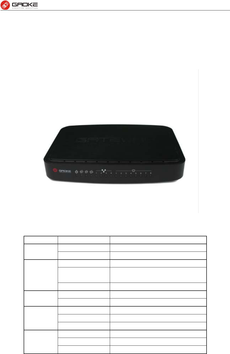
2.1 Appearance
Figure 2-1 FG7008N Front View
Table 2-1 LED
LED Status Indication
PWR Off Power is off
Solid Green Device is running
INTERNET
Off Power is off
Slow Flash Green INTERNET type WAN PPPoE connection
authenticate failed
Solid Green INTERNET type WAN connection is up
SFP Off No optical signal is detected
Solid Green Optical signal is detected
WAN
Off No Ethernet signal is detected
Flash Green User data going through Ethernet port
Solid Green Ethernet interface is ready to work
LAN1~LAN4
Off No Ethernet signal is detected
Flash Green User data going through Ethernet port
Solid Green Ethernet interface is ready to work
FG7008N User Manual
Page 3 of 111
Phone1&2 Off Phone is onhook
Solid Green Phone is offhook
VPN Off No VPN connection
Solid Green VPN is established
REG
Off All accounts register failure
Solid Green All accounts register successfully
Flash Green Some accounts register successfully and
rest register fails
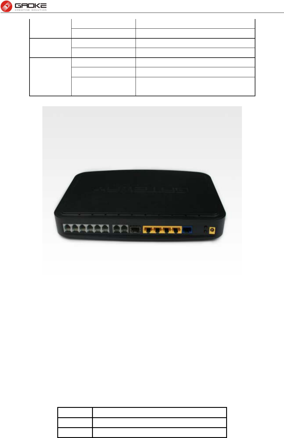
Figure 2-2 FG7008N Rear View
WAN: 1000/100/10Mpbs ethernet ports.
LAN(N): 1000/100/10Mpbs ethernet ports.
SFP: Gigabit fiber interface.
SD: Interface for SD card.
FXS: Analog telephone interface.
POWER: DC power input connector.
Reset button: Use the button to restore the device to the factory defaults.
WPS: WIFI WPS switch.
2.2 Hardware Interface
Table 2-2 Hardware interface
LAN 4 100/1000BASE-T ports
WAN 1 FE ethernet port or 1 GE optical port
WIFI 4 WIFI access point, support 802.11b/g/n

FG7008N User Manual
Page 4 of 111
SFP 1 Gigabit fiber interface
USB 1 USB 2.0 port, use for storage or 3G modem
2.3 Features
Data Network
WAN: 1xGE,1xSFP and 1xUSB port for 2G/3G USB Modem Connectivity
LAN: 2x10/100/1000 Mbps Ethernet Port
WAN Access Mode: Static IP address, PPPoE, DHCP, PPTP and L2TP
Networking Interface: Multi WAN, Bridge Mode, 802.1Q
QOS: Destination/Source MAC/IP, Application, DSCP, Supports Bandwidth Control
Advance Routing: Static Route, Policy Route, DNS Proxy, RIP
Internal Address Management: DHCP Server, IP and MAC Address Bind, DHCP Relay
Networking Protocols: TCP/IP(IPv4/v6),UDP,RTP,SNTP,NAT,DHCP,DNS,DDNS,DLNA
VPN: IPSEC,PPTP,L2TP
IPTV: IGMP Proxy/Snooping, IPTV Bridge
Management
Management Protocol: CLI,SNMPV1/2,Tr069,Web
LED Indications: Total 12LEDS for Power, WAN/LAN, Phone
Control Button: WPS Button, WLAN Button, Power Switch, Reset Button
NAT
Supports ALG, DMZ, PAT
Firewall & Security
Firewall Protection: IDS&IPS, Block Ping/ICMP/IDENT, SPI Firewall, Portscan restriction
Access control: Blocking by URL,IP Address, Mac Address, Protocol Type, Port
WIFI WLAN
Standard: IEEE 802.11b/g/n(2.4GHz)
Security: WEP,WPA,WPA2,PWA-PSK,WPA2-PSK
WIFI Features: WMM,WLAN-LAN Isolation, Multi SSID(X4), AP Isolation
Antenna Type: 2R2T
Voice Capacity and Functions
Analog User/Co line: 2/4/8xLines FXS/FXO
Centrex Functions List
Call Forward on Busy
Call Forward on No Answer
Call Forward Unconditional
Caller ID
Caller ID on Call Waiting
Call Waiting

FG7008N User Manual
Page 5 of 111
Three-way Calling
Ring groups
USB storage/Print
Support USB storage
Support print sharing
2.4 Working Environment
Environment requirement includes storage temperature, working temperature and humidity.
1) Storage Temperature: -40ºC - 70ºC
2) Long Time Working Temperature: -10ºC - 50ºC
3) Short Time Working Temperature: -15ºC - 60ºC
4) Environment Humidity: 5% - 95% RH, no coagulation
FG7008N User Manual
Page 6 of 111
3 Configuration Introduction
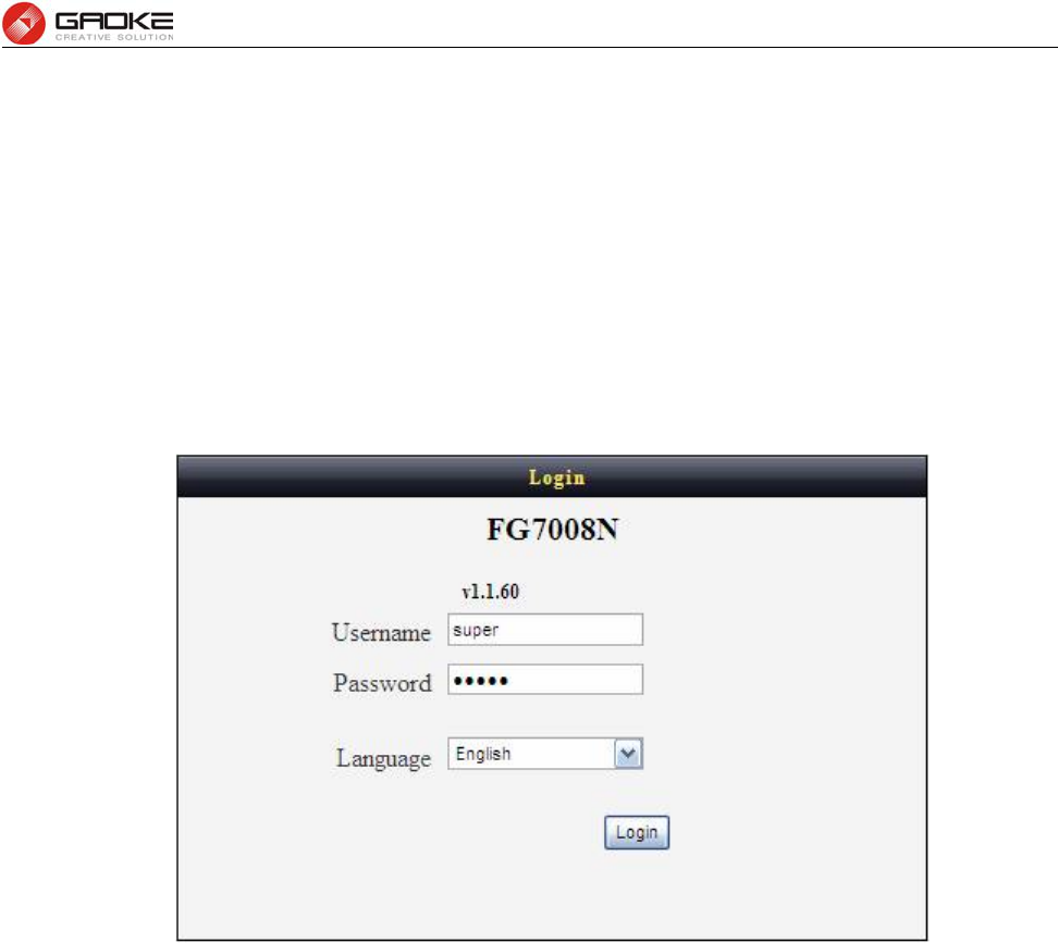
3.1 Login
The Web interface is ready for accessing about one minute after the device power on. The default
LAN IP address is 192.168.100.1, you can access the Web interface via either WAN port or LAN
port. Enter IP address in the address bar of web browser and then press ENTER, you can get
access to the Login interface.There are two languages provided: Chinese and English.
Figure 3-1 Login Interface
3.2 Home
After successful login, you will see the main menus on the top of the Web-based GUI.
The System Status page provides the current status information about the Gateway. All information is
read-only.
Choose the menu Home to load the following page.
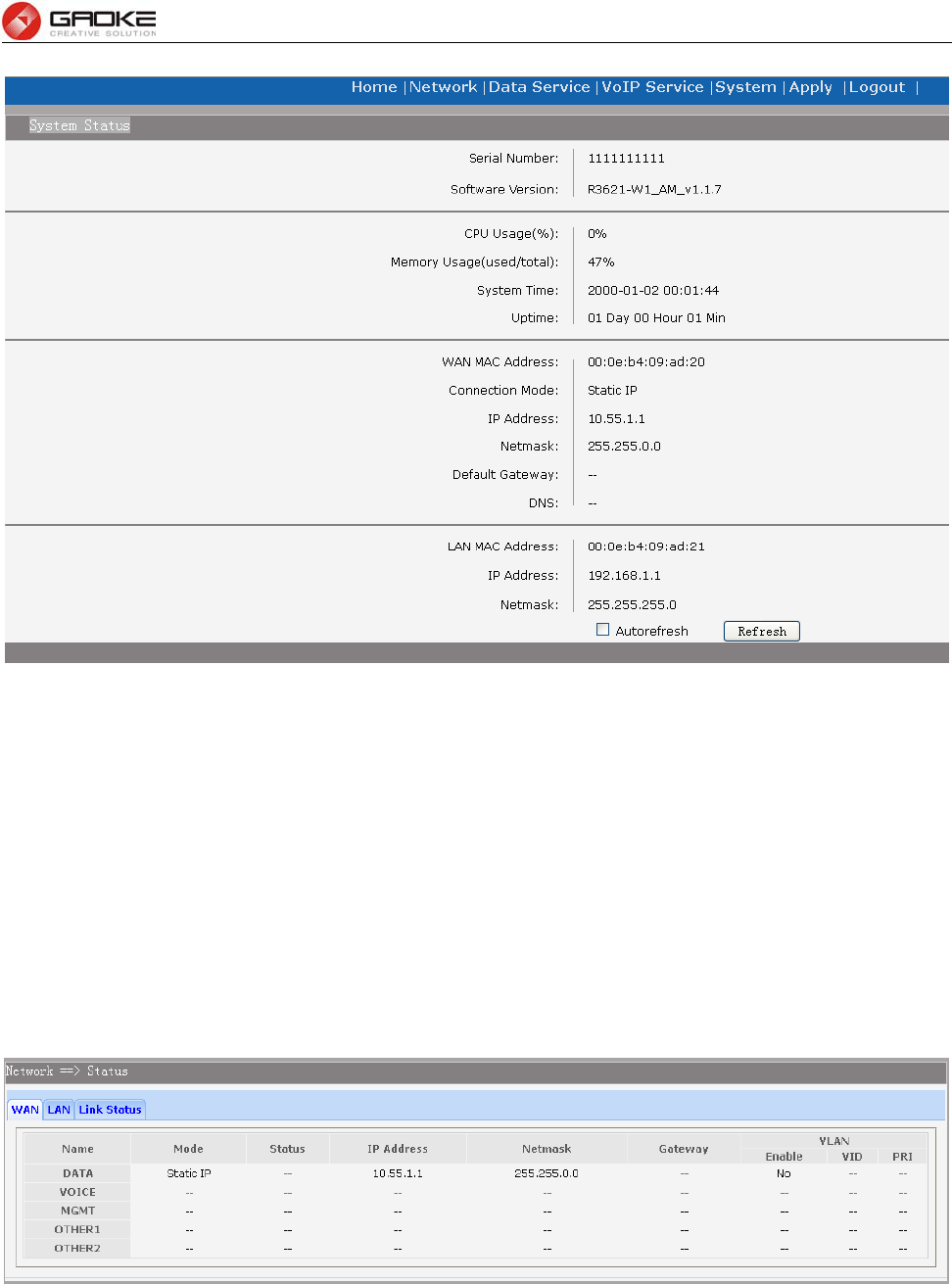
FG7008N User Manual
Page 7 of 111
Figure 3-2 System Status
3.3 Network Configuration
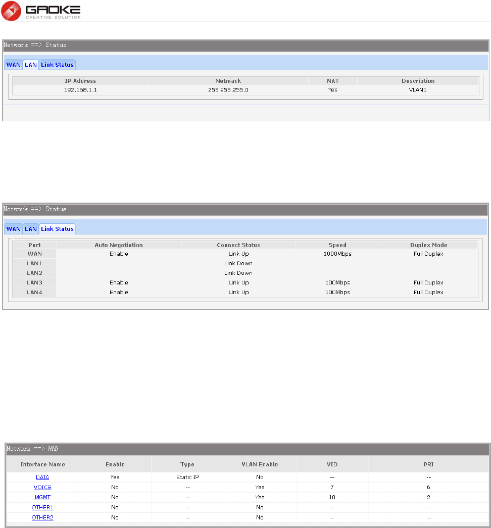
3.3.1 Network Status
The Status page shows all WAN and LAN interfaces configuration, and all physical ports connection
status related to this device.
3.3.1.1 WAN Status
Choose the menu Network→Status→WAN to load the following page.
Figure 3-3 WAN Status
3.3.1.2 LAN Status
Choose the menu Network→Status→LAN to load the following page.
FG7008N User Manual
Page 8 of 111
Figure 3-4 LAN Status
3.3.1.3 Link Status
Choose the menu Network→Status→Link Status to load the following page.
Figure 3-5 Link Status
3.3.2 WAN Configuration
The device supports 5 WAN interfaces:DATA,VOICE,MGMT,OTHER1,OTHER2; Every WAN interface
provides the following five Internet connection types: Static IP,DHCP,PPPoE,PPTP,L2TP.
Choose the menu Network→WAN to load the configuration show page.
Figure 3-6 WAN page
Select an Interface Name to load the configuration page.
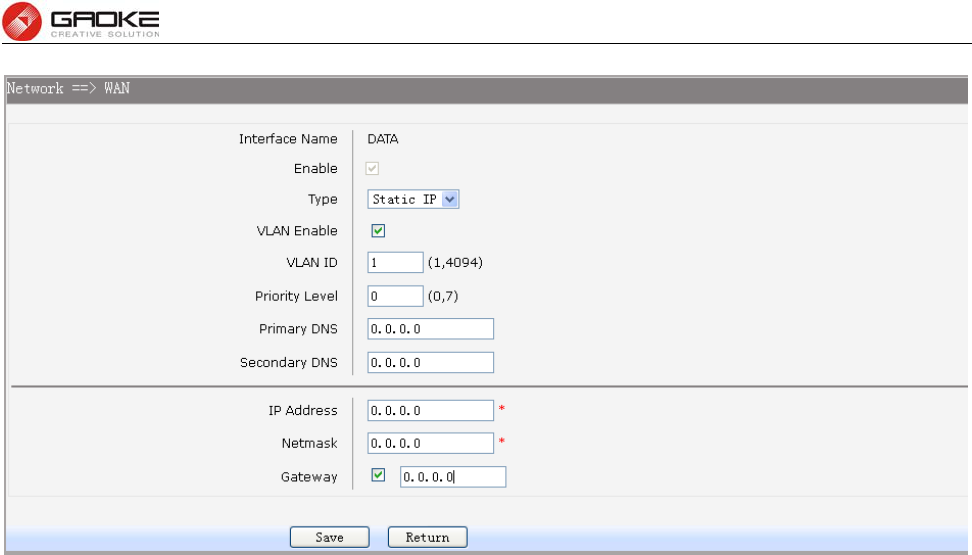
1) Static IP
If a static IP address has been provided by your ISP, please choose the Static IP connection type to
configure the parameters for WAN port manually.
FG7008N User Manual
Page 9 of 111
Figure 3-7 WAN-Static IP
The following items are displayed on this screen:
► Enable: Enable this WAN interface (DATA can’t be disabled).
► Type: Select Static IP if your ISP has assigned a static IP address for your.
► VLAN Enable: Optional. Enable VLAN to configure VLAN ID and VLAN Priority Level.
► VLAN ID: Optional. VLAN ID of this WAN interface.
► Priority Level: Optional. VLAN Priority Level of this WAN interface.
► Primary DNS: Enter the IP address of your ISP’s Primary DNS (Domain Name Server). If you are
not clear, please consult your ISP. It’s not allowed to access the Internet via
domain name if the Primary DNS field is blank.
► Secondary DNS: Optional. If a Secondary DNS Server address is available, enter it.
► IP Address: Enter the IP address assigned by your ISP. If you are not clear, please consult your
ISP.
► Netmask: Enter the Subnet Mask assigned by your ISP.
► Gateway: Optional. Enter the Gateway assigned by your ISP.
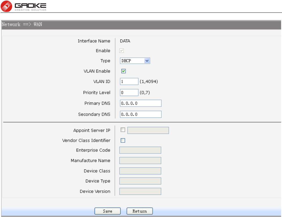
2) DHCP
If your ISP (Internet Service Provider) assigns the IP address automatically, please choose the DHCP
connection type to obtain the parameters for WAN port automatically.
FG7008N User Manual
Page 10 of 111
Figure 3-8 WAN-DHCP
The following items are displayed on this screen:
► Enable: Enable this WAN interface (DATA can’t be disabled).
► Type: Select DHCP if your ISP assigns the IP address automatically.
► VLAN Enable: Optional. Enable VLAN to configure VLAN ID and VLAN Priority Level.
► VLAN ID: Optional. VLAN ID of this WAN interface.
► Priority Level: Optional. VLAN Priority Level of this WAN interface.
► Primary DNS: Enter the IP address of your ISP’s Primary DNS (Domain Name Server)
manually. If you are not clear, please consult your ISP. It’s not allowed to
access the Internet via domain name if the Primary DNS field is blank.
► Secondary DNS: Optional. If a Secondary DNS Server address is available, enter it.
► Appoint Server IP: Optional. If network has multiple DHCP servers, enter the IP address of your
ISP’S DHCP server
► Vendor Class Identifier: Optional. This option (60) is used by DHCP clients to optionally identify the
vendor type and configuration of a DHCP client.
► Enterprise Code: Optional.
► Manufacture Name: Optional.
► Device Class: Optional.
► Device Type: Optional.
► Device Version: Optional.
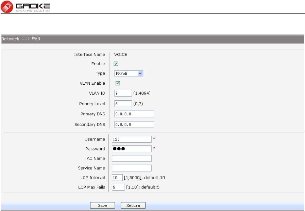
3) PPPoE
If your ISP (Internet Service Provider) has provided the account information for the PPPoE connection,
FG7008N User Manual
Page 11 of 111
please choose the PPPoE connection type (Used mainly for DSL Internet service).
Figure 3-9 WAN-PPPoE
The following items are displayed on this screen:
► Enable: Enable this WAN interface (DATA can’t be disabled).
► Type: Select PPPoE if your ISP provides xDSL Virtual Dial-up connection.
► VLAN Enable: Optional. Enable VLAN to configure VLAN ID and VLAN Priority Level.
► VLAN ID: Optional. VLAN ID of this WAN interface.
► Priority Level: Optional. VLAN Priority Level of this WAN interface.
► Primary DNS: Enter the IP address of your ISP’s Primary DNS (Domain Name Server)
manually. If you are not clear, please consult your ISP. It’s not allowed to
access the Internet via domain name if the Primary DNS field is blank.
► Secondary DNS: Optional. If a Secondary DNS Server address is available, enter it.
► Username: Enter the Account Name provided by your ISP. If you are not clear, please
consult your ISP.
► Password: Enter the Password provided by your ISP.
► Service Name /AC Name: Optional. The service name and AC (Access Concentrator) name, which
should not be configured unless you are sure it is necessary for your ISP. In
most cases, leaving these fields blank will work.
► LCP Interval: PPPoE will send an LCP echo-request frame to the peer every LCP interval
seconds.
► LCP Max Fails: PPPoE will presume the peer to be dead if LCP Max Fails LCP echo-requests
are send without receiving a valid LCP echo-reply.
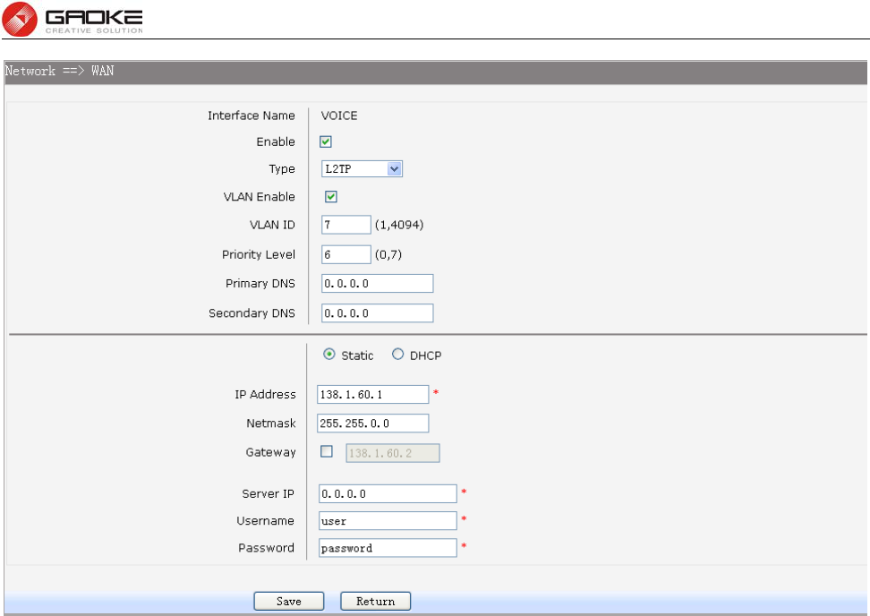
4) L2TP
If your ISP (Internet Service Provider) has provided the account information for the L2TP connection,
please choose the L2TP connection type.
FG7008N User Manual
Page 12 of 111
Figure 3-10 WAN-L2TP
The following items are displayed on this screen:
► Enable: Enable this WAN interface (DATA can’t be disabled).
► Type: Select L2TP if your ISP provides a L2TP connection.
► VLAN Enable: Optional. Enable VLAN to configure VLAN ID and VLAN Priority Level.
► VLAN ID: Optional. VLAN ID of this WAN interface.
► Priority Level: Optional. VLAN Priority Level of this WAN interface.
► Primary DNS: Enter the IP address of your ISP’s Primary DNS (Domain Name Server). If
you are not clear, please consult your ISP. It’s not allowed to access the
Internet via domain name if the Primary DNS field is blank.
► Secondary DNS: Optional. If a Secondary DNS Server address is available, enter it.
► Server IP: Enter the Server IP provided by your ISP.
► Username: Enter the Account Name provided by your ISP. If you are not clear, please
consult your ISP.
► Password: Enter the Password provided by your ISP.
Secondary Connection: Here allow you to configure the secondary connection. DHCP and Static IP
connection types are provided.
If Static is selected:
► IP Address: If Static IP is selected, configure the IP address of WAN port.
► Netmask: If Static IP is selected, configure the subnet mask of WAN port.
► Gateway: Optional. If Static IP is selected, configure the default gateway of WAN port.
If DHCP is selected:
► Appoint Server IP: Optional. If network has multiple DHCP servers, enter the IP address of your
ISP’s DHCP server.
►Vendor Class Identifier: Optional. This option (60) is used by DHCP clients to optionally identify the
FG7008N User Manual
Page 13 of 111
vendor type and configuration of a DHCP client.
► Enterprise Code: Optional.
► Manufacture Name: Optional.
► Device Class: Optional.
► Device Type: Optional.
► Device Version: Optional.
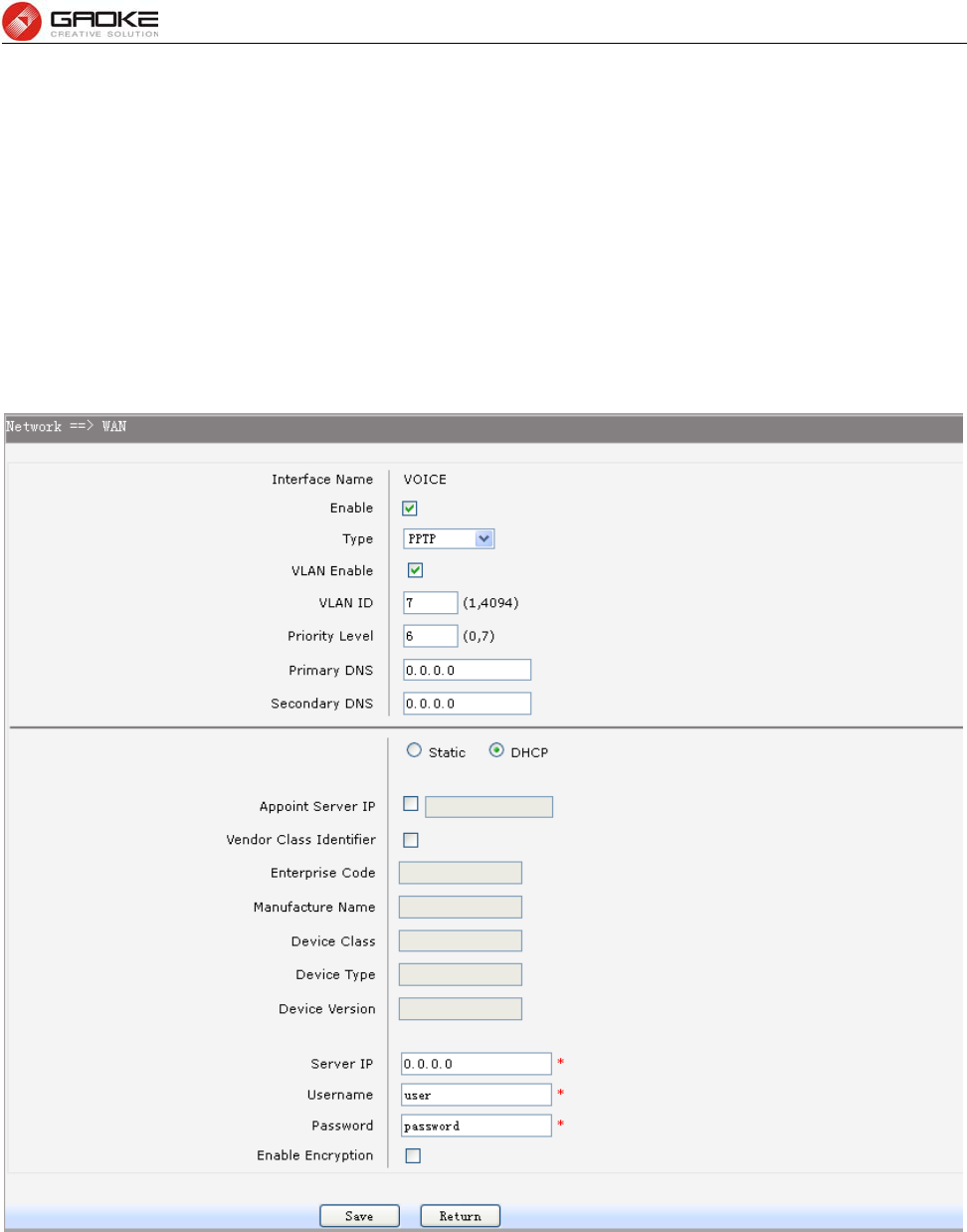
5) PPTP
If your ISP (Internet Service Provider) has provided the account information for the PPTP connection,
please choose the PPTP connection type.
Figure 3-11 WAN-PPTP
The following items are displayed on this screen:
► Enable: Enable this WAN interface (DATA can’t be disabled).
► Type: Select PPTP if your ISP provides a PPTP connection.
► VLAN Enable: Optional. Enable VLAN to configure VLAN ID and VLAN Priority Level.
► VLAN ID: Optional. VLAN ID of this WAN interface.
► Priority Level: Optional. VLAN Priority Level of this WAN interface.
► Primary DNS: Enter the IP address of your ISP’s Primary DNS (Domain Name Server)

FG7008N User Manual
Page 14 of 111
manually. If you are not clear, please consult your ISP. It’s not allowed to
access the Internet via domain name if the Primary DNS field is blank.
► Secondary DNS: Optional. If a Secondary DNS Server address is available, enter it.
► Server IP: Enter the Server IP provided by your ISP.
► Username: Enter the Account Name provided by your ISP. If you are not clear, please
consult your ISP.
► Password: Enter the Password provided by your ISP.
► Enable Encryption: Enable PPTP link encryption.
Secondary Connection: Here allow you to configure the secondary connection. DHCP and Static IP
connection types are provided.
If Static is selected:
► IP Address: If Static IP is selected, configure the IP address of WAN port.
► Netmask: If Static IP is selected, configure the subnet mask of WAN port.
► Gateway: Optional. If Static IP is selected, configure the default gateway of WAN port.
If DHCP is selected:
► Appoint Server IP: Optional. If network has multiple DHCP servers, enter the IP address of your
ISP’s DHCP server.
►Vendor Class Identifier: Optional. This option (60) is used by DHCP clients to optionally identify the
vendor type and configuration of a DHCP client.
► Enterprise Code: Optional.
► Manufacture Name: Optional.
► Device Class: Optional.
► Device Type: Optional.
► Device Version: Optional.
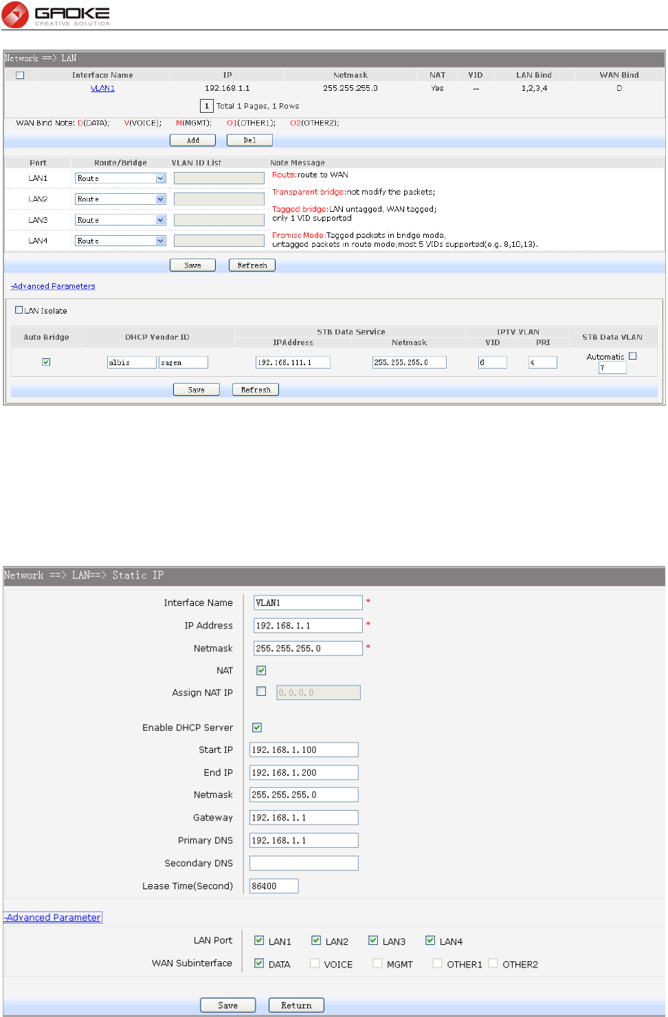
3.3.3 LAN Configuration
On this page, you can configure the parameters for LAN port.
Choose the menu Network→LAN to load the following page. There are three parts on this page.
FG7008N User Manual
Page 15 of 111
Figure 3-12 LAN page
1) Part 1: Configure LAN interfaces
Click the Interface Name of existent LAN interface you want to modify. If you want to delete the entry,
select it and click the Del (the VLAN1 is default existed, can’t be removed).
Click the Add button to add a new entry.
Figure 3-13 Configure LAN Interface

FG7008N User Manual
Page 16 of 111
The following items are displayed on this part.
► Interface Name: Name of this LAN interface.
► IP Address: Enter the IP address for this LAN interface.
► Netmask: Enter the subnet mask for this LAN interface.
► NAT: Optional Enable or disable NAT for this LAN interface
► Assign NAT IP: Optional If NAT is selected. NAT IP address can be assigned.
► Enable DHCP Server: Enable or disable DHCP server on this LAN interface.
► Start IP: If Enable DHCP Server is selected, enter the Start IP address to define a
range for the DHCP server to assign dynamic IP addresses. This address
should be in the same IP address subnet with the IP address of this LAN
interface.
► End IP: If Enable DHCP Server is selected, enter the End IP address to define a
range for the DHCP server to assign dynamic IP addresses. This address
should be in the same IP address subnet with the IP address of this LAN
interface.
► Netmask: If Enable DHCP Server is selected, enter the Netmask to define a range for
the DHCP server to assign dynamic IP addresses.
► Gateway: Optional .If Enable DHCP Server is selected, enter the Gateway address to
be assigned.
► Primary DNS: Optional. If Enable DHCP Server is selected, enter the Primary DNS server
address to be assigned.
► Secondary DNS: Optional. If Enable DHCP Server is selected, enter the Secondary DNS
server address to be assigned.
► Lease Time(Second): If Enable DHCP Server is selected, specify the length of time the DHCP
server will reserve the IP address for each client. After the IP address
expired, the client will be automatically assigned a new one.
Advanced Parameter
► LAN Port: Select the physical LAN port to bind the IP address of this LAN interface.
► WAN Subinterface: Select the WAN subinterface which the packet from this LAN interface can
be sending to.
2) Part 2: Configure LAN Route/Bridge mode
The following items are displayed on this part.
► Port: The physical LAN port name (LAN1~LAN4).
► Route/Bridge: Mode of this physical LAN port. The following four modes are provided:
Route: route to WAN
Transparent bridge: not modify the packets;
Tagged bridge: LAN untagged, WAN tagged; only 1 VID supported
Promisc Mode: Tagged packets in bridge mode, untagged packets in route mode;
most 5 VIDs supported (e.g. 8, 10, 13).
► VLAN ID List: If Tagged bridge/Promisc Mode is selected, configure the VID/VIDs.
3) Part 3: Configure IPTV
FG7008N User Manual
Page 17 of 111
Choose the menu Network→LAN→Advanced Parameters to load this page.
The following items are displayed on this part.
► LAN Isolate: Check the box to prohibit the access between LAN interfaces.
► Auto Bridge: Check the box to dynamically create IPTV bridge for STB.
► DHCP Vendor ID: Vendor class identifier List (DHCP 60 option), support at most two vendor IDs.
► IPAddress: IP address of interface for STB data service.
► Netmask: Subnet mask of interface for STB data service.
► VID: VID of IPTV VLAN.
► PRI: Priority level of IPTV VLAN.
► Automatic: Check the box to automatically detect the VID of STB data service.
3.3.4 WLAN
Wi-Fi is a WLAN (Wireless Local Area Network) technology. It provides short-range wireless high-speed
data connections between mobile data devices (such as laptops, PDAs or phones) and nearby Wi-Fi
access points (special hardware connected to a wired network).
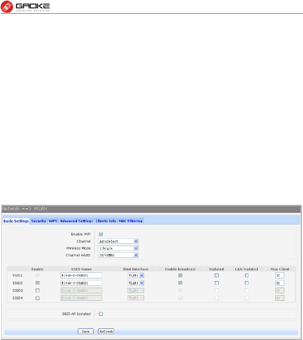
3.3.4.1 Basic Settings
Choose the menu Network→WLAN→Basic Settings to load the following page.
Figure 3-14 Configure WIFI Basic Settings
The following items are displayed on this screen:
► Enable WiFi: Enable or disable the WIFI AP function globally.
► Channel: This field determines which operating frequency will be used. The default channel is
set to AutoSelect, so the AP will choose the best channel automatically. It is not
necessary to change the wireless channel unless you notice interference problems
with another nearby access point.
► Wireless Mode: Select the desired mode.
11b: Select if all of your wireless clients are 802.11b.
11g: Select if all of your wireless clients are 802.11g.
11n: Select only if all of your wireless clients are 802.11n.
11b/g: Select if you are using both 802.11b and 802.11g wireless clients.
11b/g/n: Select if you are using a mix of 802.11b, 11g and 11n wireless clients.
FG7008N User Manual
Page 18 of 111
► Channel Width: Select any channel width from the drop-down list. The default setting is automatic,
which can automatically adjust the channel width for your clients. If you choose to
11n or 11b/g/n Wireless mode, this configuration is required. Two values of width
are provided: 20MHz and 20/40MHz.
The Service Set Identifier (SSID) is used to identify an 802.11 (Wi-Fi) network and it’s discovered by
network sniffing/scanning. FG7008N provides up to four SSID.
► Enable: Enable or disable this entry of SSID. SSID1 can’t be disabled.
►SSID Name: Enter the name of SSID. The name of SSID must be unique in all wireless
networks nearby.
► Bind Interface: Select a network interface to be bridged to the SSID.
► Enable Broadcast: When wireless clients survey the local area for wireless networks to associate
with, they will detect the SSID broadcast by the device. If you select the Enable
Broadcast checkbox, the device will broadcast its name (SSID) on the air.
► Isolated: Enable or disable isolate different clients from the same wireless station.
► LAN Isolated: Enable or disable isolation between the LAN and SSID.
► Max Client: Enter the maximum number of clients allowed to connect to the SSID.
► SSID AP Isolated: This function can isolate wireless stations on your network from each other.
Wireless devices will be able to communicate with the Router but not with each
other. To use this function, check this box. AP Isolation is disabled by default.
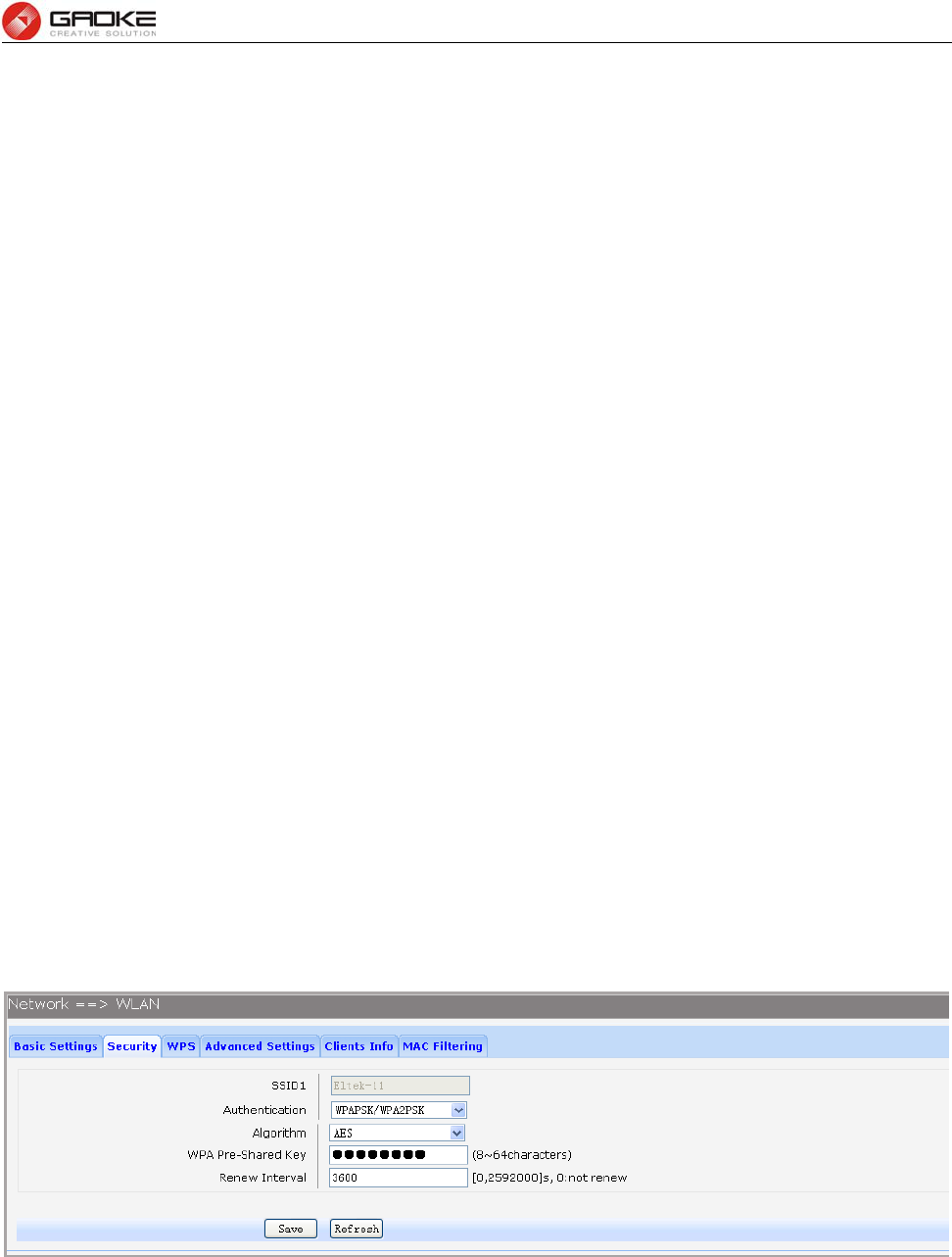
3.3.4.2 Security
Choose the menu Network→WLAN→Security to load the Security page. There are nine wireless
security modes supported by the device: Open WEP, Shared WEP, WEP Auto, WPA-PSK, WPA2-PSK,
WPAPSK/WPA2PSK, WPA, WPA2 and WPAWPA2.
If you do not want to use wireless security, select Disable, but it’s strongly recommended to choose one
of the following modes to enable security.
1) WPA-PSK, WPA2-PSK, WPAPSK/WPA2PSK: It’s the WPA/WPA2 authentication type based on
pre-shared passphrase. Choose one of these types, the following page is loaded.
Figure 3-15 Configure WIFI PSK Security
The following items are displayed on this screen:
► SSID: The SSID enabled in WLAN→Basic Settings page.Read only
► Authentication: The authentication type selected: WPA-PSK, WPA2-PSK, WPAPSK/WPA2PSK.
► Algorithm: When WPA2-PSK or WPAPSK/WPA2PSK is set as the Authentication Type,
you can select either TKIP, or AES or TKIP/AES as Encryption. When
WPA-PSK is set as the Authentication Type, you can select either TKIP or AES
FG7008N User Manual
Page 19 of 111
as Encryption.
► WPA Pre-Shared Key: You can enter ASCII characters between 8 and 64 characters.
► Renew Interval: Specify the group key update interval in seconds. Enter 0 to disable the update.
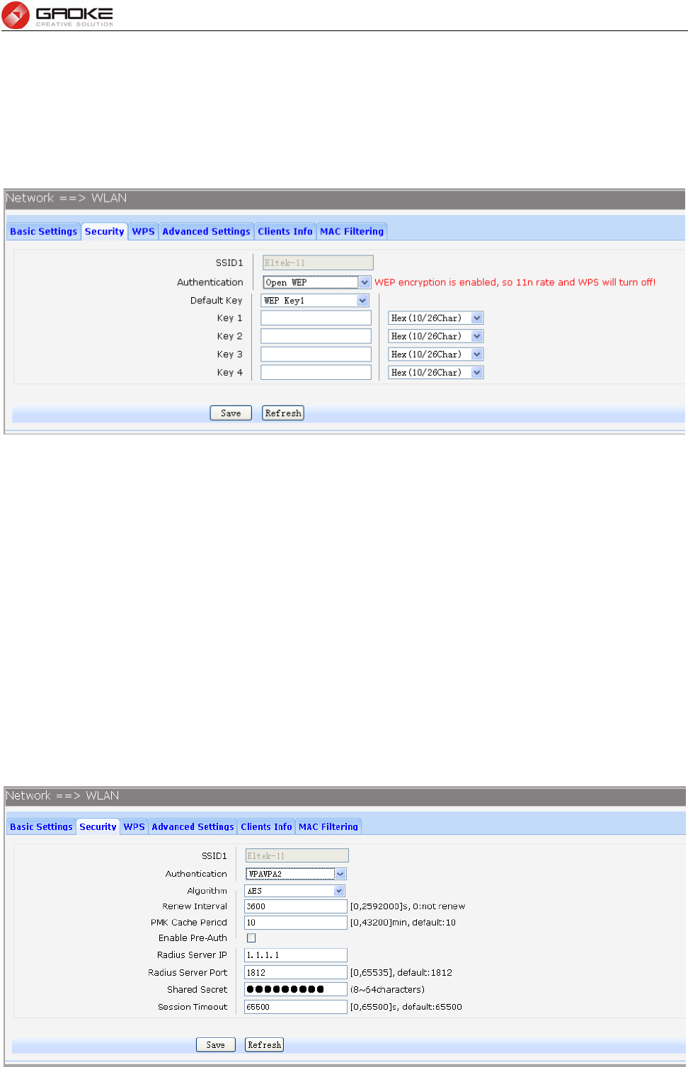
2) Open WEP, Shared WEP, WEP Auto: It is based on the IEEE 802.11 standard. Choose one of these
types, the following page is loaded.
Figure 3-16 Configure WIFI WEP Security
The following items are displayed on this screen:
► SSID: The SSID enabled in WLAN→Basic Settings page.Read only
► Authentication: The authentication type selected: Open WEP, Shared WEP, WEP Auto.
► Default Key: Select the default WEP key configure below.
► Key: Provide up to four key. You can select the key type HEX(10/26 char) or ASCII(5/13
char)) for encryption and then enter the key. HEX(10/26 char) and ASCII(5/13 char)
formats are provided.
Hex(10/26 char): format stands for any combination of hexadecimal digits (0-9, a-f,
A-F) in the specified length.
ASCII(5/13 char): format stands for any combination of keyboard characters in the
specified length.
3) WPA, WPA2, WPA/WPA2: It’s based on Radius Server. Choose one of these types, the following
page is loaded.
FG7008N User Manual
Page 20 of 111
Figure 3-17 Configure WIFI WPA Security
The following items are displayed on this screen:
► SSID: The SSID enabled in WLAN→Basic Settings page.Read only
► Authentication: The authentication type selected: WPA, WPA2, WPA/WPA2.
► Algorithm: You can select either TKIP, or AES or TKIP/AES.
► Renew Interval: Specify the update interval in seconds. Enter 0 to disable the update.
► PMK Cache Period: Pairwise Master Key, PMK. Set WPA2 PMKID cache timeout period, after time
out, the cached key will be deleted.This parameter is valid when you select
WPA2 or WPA/WPA2.
► Enable Pre-Auth: This is used to speed up roaming before pre-authenticating IEEE 802.1X/EAP
part of the full RSN authentication and key handshake before actually
associating with a new AP. Default is disable. This parameter is valid when
you select WPA2 or WPA/WPA2.
► Rasius Server IP: Enter the IP address of the Radius Server.
► Rasius Server Port: Enter the port that radius service used.
► Shared Seret: Enter the password for the Radius Server.
► Session Timeout: Specify the session timeout in seconds, Enter 0 to not limit the timeout.
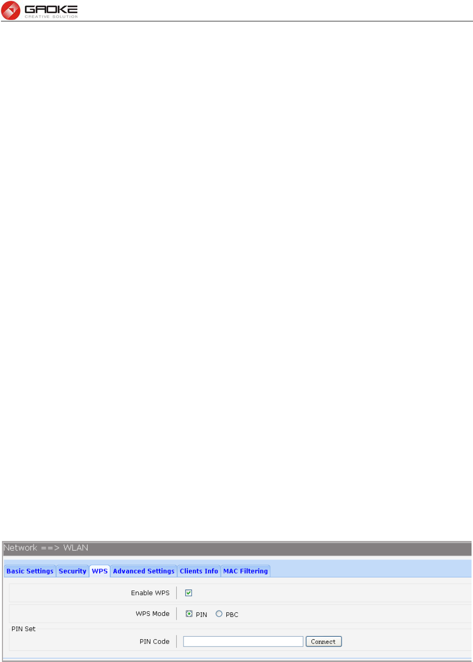
3.3.4.3 WPS
Wi-Fi Protected Setup (WPS; originally Wi-Fi Simple Config) is a computing standard that
attempts to allow easy establishment of a secure wireless home network.WPS currently supports two
methods: Personal Information Number (PIN) and Push Button Configuration (PBC).The difference
between the two methods is much pretty described in their names.
The PIN method involves entering a client device PIN, obtained either from a client application GUI
or a label on a device, into the appropriate admin screen on a Registrar device.
The PBC method requires the user to push buttons on the Registrar and Client devices within a
two-minute period to connect them. (The two-minute period also applies to the PIN method.) The buttons
can be physical, as they typically are on AP / router devices or virtual, as is normal on client devices.
Choose the menu Network→WLAN→WPS to load the WPS page.
1) PIN Mode
If PIN mode is selected, the following page is loaded.
Figure 3-18 Configure WIFI WPS-PIN
The following items are displayed on this screen:
► Enable WPS: Enable or disable the WIFI WPS function globally.
► WPS Mode: Choose the WPS mode: PIN.
FG7008N User Manual
Page 21 of 111
► PIN Code: If PIN mode is chosen, enter the 8 digit PIN code, and then click Connect.
2) PBC Mode
If PBC mode is selected, the following page is loaded.
Figure 3-19 Configure WIFI WPS-PBC
The following items are displayed on this screen:
► Enable WPS: Enable or disable the WIFI WPS function globally.
► WPS Mode: Choose the WPS mode: PBC.
► PBC Set: If PBC mode is chosen, then click Simulation Connect.
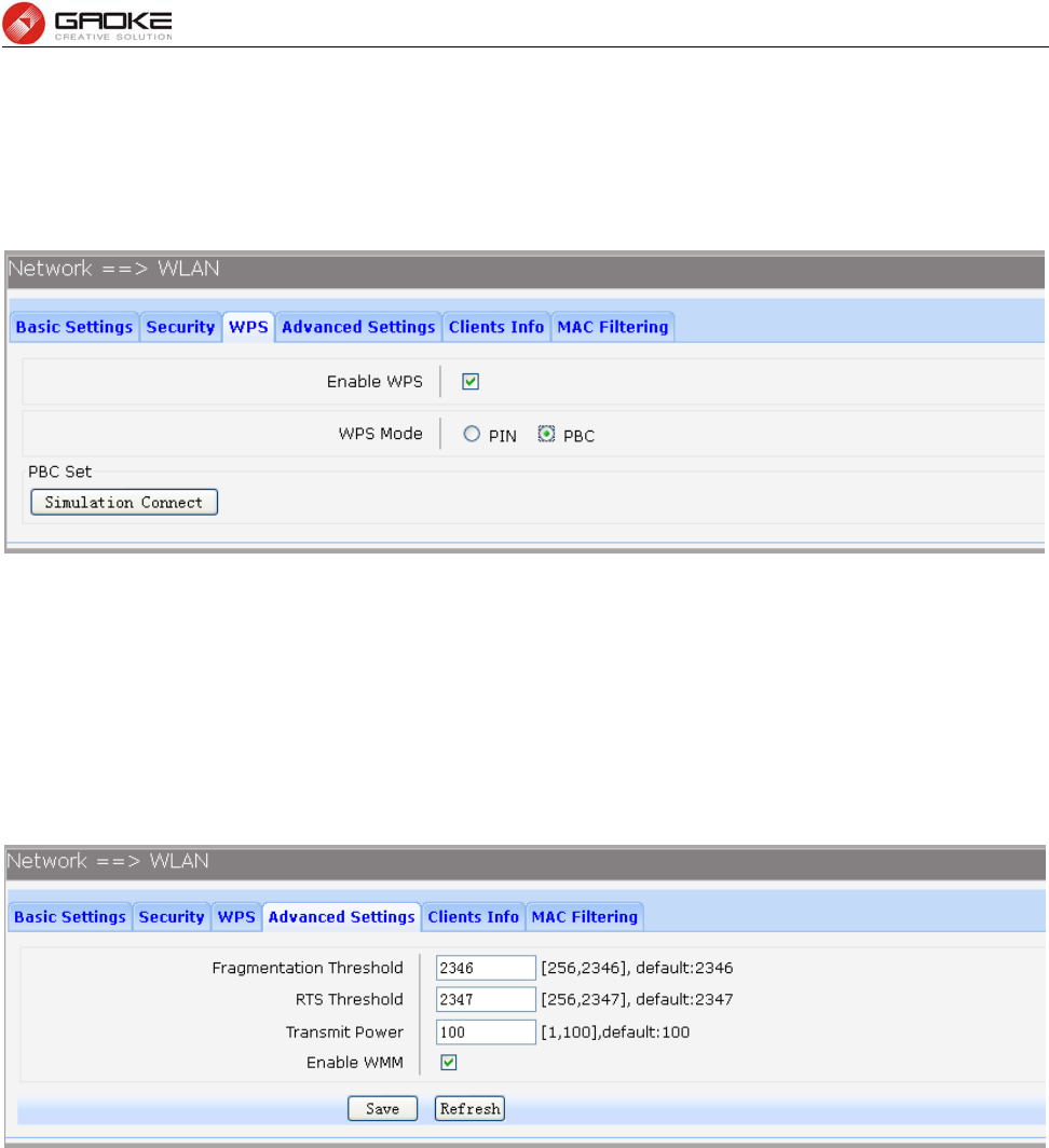
3.3.4.4 Advanced Settings
Choose the menu Network→WLAN→Advanced Settings to load the following page.
Figure 3-20 Configure WIFI Advanced Settings
The following items are displayed on this screen:
► Fragmentation Threshold: This value is the maximum size determining whether packets will be
fragmented. Setting the Fragmentation Threshold too low may result in
poor network performance since excessive packets. 2346 is the default
setting and is recommended.
► RTS Threshold: Here you can specify the RTS (Request to Send) Threshold. If the
packet is larger than the specified RTS Threshold size, the device will
send RTS frames to a particular receiving station and negotiate the
sending of a data frame. The default value is 2347.
► Transmit Power: Here you can specify the transmit power of device. 100 is the default
setting and is recommended.
► Enable WMM: Enable or disable the WIFI WMM function globally. WMM function can
guarantee the packets with high-priority messages, being transmitted
FG7008N User Manual
Page 22 of 111
preferentially. It is strongly recommended enabled.
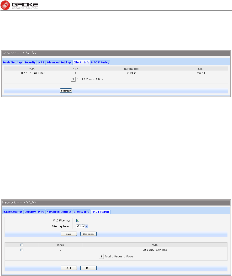
3.3.4.5 Clients Info
Choose the menu Network→WLAN→Clients Info to load the following page.
Figure 3-21 View Wifi Clients Info
This page shows all connected WIFI client information, read only.
The following items are displayed on this screen:
► MAC: The MAC address of this client entry.
► AID: The AID(Association ID) field is a value assigned by an AP during association that
represents the 16-bit ID of a STA.
► Bandwidth: Band width this client entry used.
► SSID: The SSID this client entry used when connecting WIFI.
3.3.4.6 MAC Filtering
You can control the wireless access by configuring the Wireless MAC Filtering function.
Choose the menu Network→WLAN→MAC Filtering to load the following page.
Figure 3-22 View Wifi MAC Filtering
The following items are displayed on this screen:
► MAC Filtering: Enable or disable the Wifi MAC filtering function globally.
► Filtering Rules: Two MAC filtering rules are provided:
Allow: allow the stations specified by entries in the list to access.
Deny: deny the stations specified by entries in the list to access.
To delete Wireless MAC Address filtering entries, select the entries and click the Del button. To Add a
Wireless MAC Address filtering entry, click the Add button.
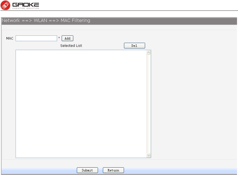
FG7008N User Manual
Page 23 of 111
Figure 3-23 Add WIFI MAC Filtering Entry
Enter the appropriate MAC Address into the MAC field. The format of the MAC Address is
XX:XX:XX:XX:XX:XX (X is any hexadecimal digit). Click Add button to add MAC address to the
Selected List, click Del button to delete the selected MAC address in the Selected List.
3.3.5 3G Modem
Typically, 3G Modem WAN is used as uplink port as a backup. When inserting 3G Modem into USB port,
the system recognized the SIM card and charges no problem. After dialing successful, 3G Modem will
serve as a backup uplink usage.
1) Basic Settings
Choose the menu Network→3G Modem to load the following page.
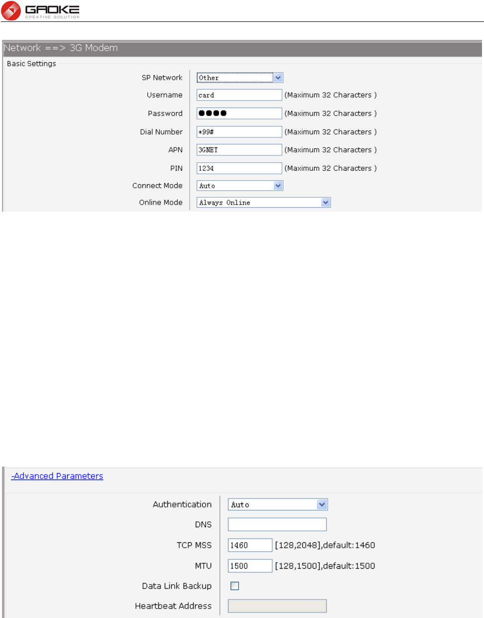
FG7008N User Manual
Page 24 of 111
Figure 3-24 Configure 3G Modem-Basic Settings
The following items are displayed on this screen:
► SP Network: Other or Swisscom. If it is not the target user, you need to select the other.
► Connect Mode: Manual or Auto. The default is Auto.
► Online Mode: always online and disconnect after idle interval. The default is “always online”.
The default idle interval is 60 seconds.
If Other is selected, the following parameters appear:
► Username: 3G network dial-up username.
► Password: 3G network dial-up password.
► Dial Number: 3G network dial numbers.
► APN: 3G network access APN.
► PIN: 3G networks need to use dial-up PIN code, if not, can be set to empty.
2) Advanced Parameters
Choose the menu Network→3G Modem→Advanced Parameters to load the following page.
Figure 3-25 Configure 3G Modem-Advanced Parameters
The following items are displayed on this screen:
► Authentication: 3G dial-up authentication, CHAP,PAP,Auto are provided. Default is Auto.
► DNS: The default is obtained from the dial-up network devices automatically. You can
also configure DNS manually.
► TCP MSS: Configure TCP maximum segment, we recommend using the default value.
► MTU: Configure 3G link MTU, the default value is recommended
► Data Link Backup: When enabled, if WAN uplink port is disconnected, the routing switches to the 3G
FG7008N User Manual
Page 25 of 111
link.
► Heartbeat Address: Set the heartbeat detecting address of the link, the default configuration is not
required.
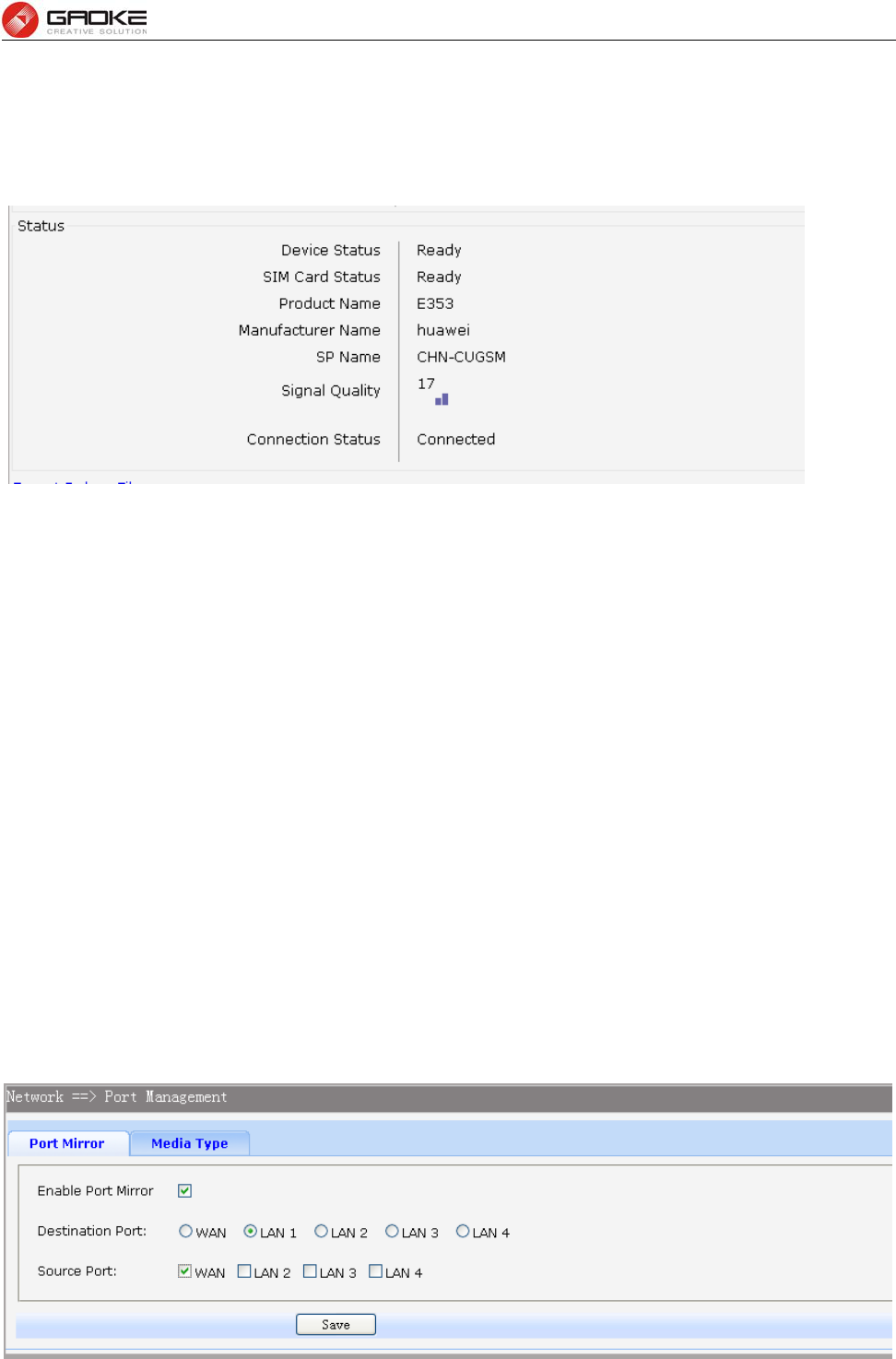
3) Status
Figure 3-26 Configure 3G Modem-Status
The following items are displayed on this screen:
► Device Status: Indicates whether to insert 3G module.
► SIM Card Status: Indicates whether to insert 3G modem in the SIM card, the ready state means
the SIM card is detected.
► Product Name: 3G modem Product Type.
► Manufacturer Name: 3G modem vendor name.
► SP Name: 3G modem service provider name.
► Signal Quality: Signal quality of 3G Modem, up to 31.
► Connection Status: Connected or disconnected.
3.3.6 Port Management
3.3.6.1 Port Mirror
Port Mirror, the packets obtaining technology, functions to forward copies of packets from one/multiple
ports (mirrored port) to a specific port (mirroring port). Usually, the mirroring port is connected to a data
diagnose device, which is used to analyze the mirrored packets for monitoring and troubleshooting the
network.
Choose the menu Network→Port Management→Port Mirror to load the following page.
FG7008N User Manual
Page 26 of 111
Figure 3-27 Port Mirror
The following items are displayed on this screen:
► Enable Port Mirror: Enable or disable port mirror.
► Destination Port: The duplicate of packets from Source Port will send to this destination port.
► Source Port: All packets received from Source Port will be duplicated and the duplicate will
be send to Destination Port.
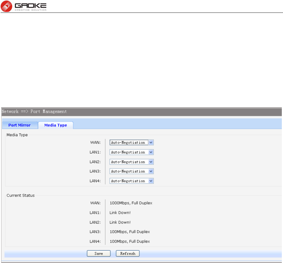
3.3.6.2 Media Type
Choose the menu Network→Port Management→Media Type to load the following page.
Figure 3-28 Media Type
The following items are displayed on this screen:
► Media Type: provides the following six modes to all physical ports: 10M Half Duplex, 10M Full
Duplex, 100M Half Duplex, 100M Full Duplex, 1000M Full Duplex,
Auto-Negotiation.
► Current Status: Current link status of all physical ports. Read only.
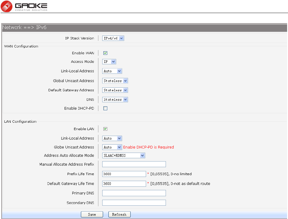
3.3.7 IPv6 Configuration
Choose the menu Network→IPv6 to load the following page.
FG7008N User Manual
Page 27 of 111
Figure 3-29 Configure IPv6
The following items are displayed on this screen:
► IP Stack Version: Choose the IP stack version to use. Provides the following three types:
IPv4,IPv6,IPv4/v6.
WAN Configuration
► Enable WAN: If IPv6 or IPv4/v6 is chosen, select this to enable IPv6 stack on WAN.
► Access Mode: Select access mode of WAN: IP or PPP.
► Link-Local Address: Select type of Link-Local address: Auto or Manual. If Manual is selected,
you should specify address manually.
► Global Unicast Address: Stateless,Manual,DHCPv6. If Manual is selected, you should specify
address manually.
► Default Gateway Address: Stateless,Manual. If Manual is selected, you should specify address
manually.
► DNS: Stateless,Manual,DHCPv6. If Manual is selected, you should specify
DNS manually.
► Enable DHCP-PD: Whether to enable DHCP-PD(prefix delegation) on WAN.
LAN Configuration
► Enable LAN: If IPv6 or IPv4/v6 is choseN, select this to enable IPv6 stack on LAN.
► Link-Local Address: Select type of Link-Local address: Auto or Manual. If Manual is selected,
you should specify address manually.
► Global Unicast Address: Manual,Auto. If Manual is selected, you should specify address
manually.
► Address Auto Allocate Mode: SLAAC+RDNSS(Recursive DNS Server)
FG7008N User Manual
Page 28 of 111
SLAAC(Stateless address autoconfiguration)+DHCPv6
DHCPv6
► Manual Allocate Address Prefix: Configure the manual allocate address prefix.
► Prefix Life Time: Enter the life time of prefix.
► Default Gateway Life Time: Enter the life time of default gateway.
► Primary DNS: Enter the primary DNS address.
► Secondary DNS: Enter the secondary DNS address.
3.4 Data Service
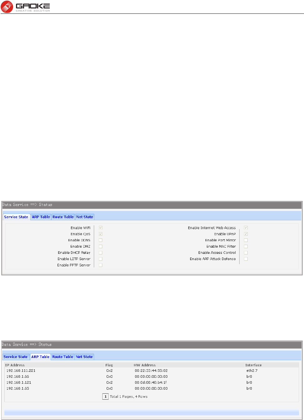
3.4.1 Status
The Status page shows the data services information, all information is read only.
3.4.1.1 Service State
The Service State page show all switch status of data services.
Choose the menu Data Service→Status→Service State to load the following page.
Figure 3-30 Service State
3.4.1.2 ARP Table
This page displays the ARP List;
Choose the menu Data Service→Status→ARP Table to load the following page.
Figure 3-31 ARP Table
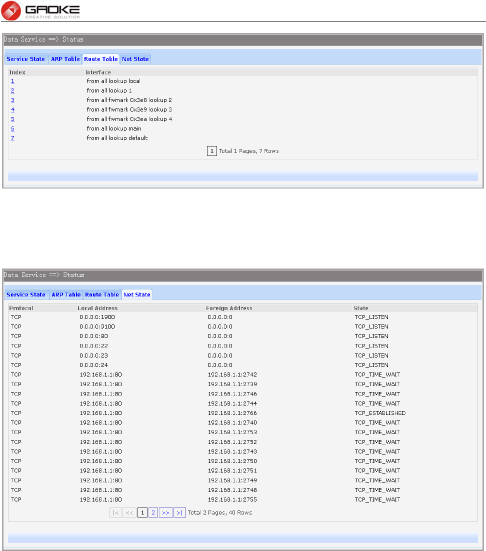
3.4.1.3 Route Table
Choose the menu Data Service→Status→Route Table to load the following page.
FG7008N User Manual
Page 29 of 111
Figure 3-32 Route Table
3.4.1.4 Net State
Choose the menu Data Service→Status→Net State to load the following page.
Figure 3-33 Net State
3.4.2 DHCP Server
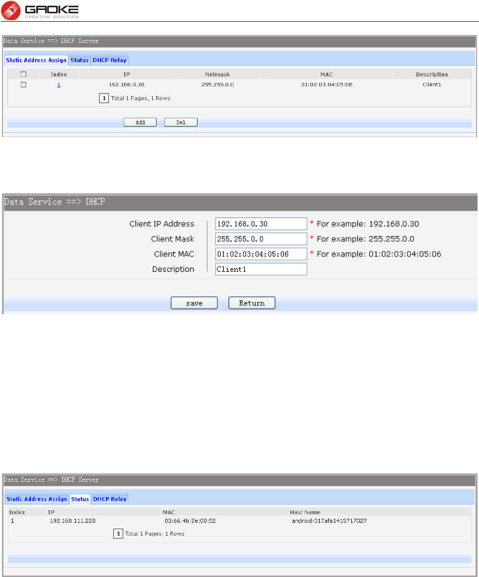
3.4.2.1 Static Address Assign
Choose the menu Data Service→DHCP Server→Static Address Assign, and then you can view and
add address which is assigned for clients. When you specify a static IP address for a client on the LAN,
that client will always receive the same IP address each time when it accesses the DHCP server. The
Reserved IP addresses should be assigned to the devices that require permanent IP settings.
FG7008N User Manual
Page 30 of 111
Figure 3-34 View Static Address Assign Configuration
Click the Index in the entry you want to modify. If you want to delete the entry, select it and click the Del.
Click the Add button to add a new entry.
Figure 3-35 Add or Modify An Static Address Assign Entry
The following items are displayed on this screen:
► Client IP Addres: The IP address reserved.
► Client Mask: The subnet mask of IP address reserved.
► Client MAC: The MAC address you want to reserve IP address.
► Description: The description of the entry to add or modify.
3.4.2.2 Status
Choose the menu Data Service→DHCP Server→Status, and then you can view the information about
the clients attached to the DHCP server.
Figure 3-36 DHCP Client Status
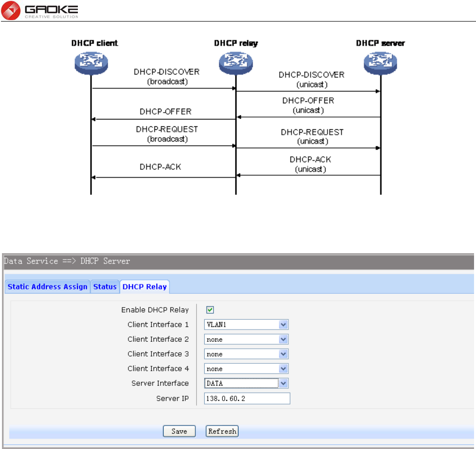
3.4.2.3 DHCP Relay
A DHCP relay agent is any host that forwards DHCP packets between clients and servers. Relay agents
are used to forward requests and replies between clients and servers when they are not on the same
physical subnet. Relay agent forwarding is distinct from the normal forwarding of an IP router, where IP
datagrams are switched between networks somewhat transparently. By contrast, relay agents receive
DHCP messages and then generate a new DHCP message to send on another interface. It listens for
client requests and adds vital configuration data, such as the client's link information, which is needed by
the server to allocate the address for the client. When the DHCP server responds, the DHCP relay agent
forwards the reply back to the DHCP client.
FG7008N User Manual
Page 31 of 111
Figure 3-37 DHCP Relay Overview
Choose the menu Data Service→DHCP Server→DHCP Relay to load the following page.
Figure 3-38 Configure DHCP Relay
The following items are displayed on this screen:
► Enable DHCP Relay: Enable or disable DHCP Relay.
► Client Interface: The interface to listen for DHCP client requests. Up to four interfaces can be
selected.
► Server Interface: Choose the interface which connects DHCP server.
► Server IP: Configure the DHCP server IP address.
3.4.3 NAT Config
Network Address Translation (NAT) is a network protocol used in IPv4 networks that allows multiple
devices to connect a network protocol using the same public IPv4 address. NAT was originally designed
in an attempt to help conserve IPv4 addresses. NAT modifies the IP address information in IPv4 headers
while in transit across a traffic routing device.
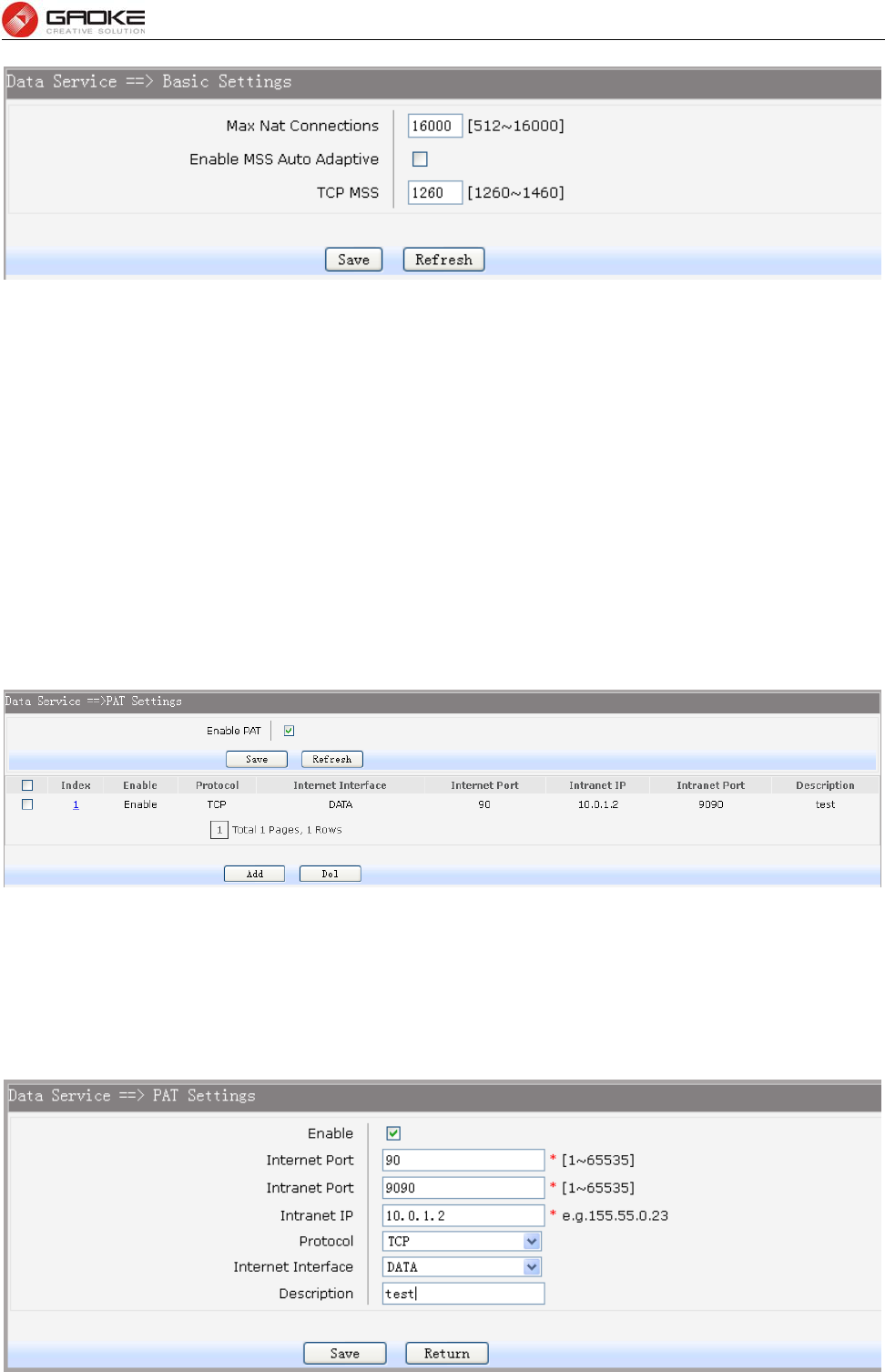
3.4.3.1 Basic Settings
Choose the menu Data Service→NAT Config→Basic Settings to load the following page.
FG7008N User Manual
Page 32 of 111
Figure 3-39 Basic Settings
The following items are displayed on this screen:
► Max Nat Connections: Specify the maximum number of NAT connections.
► Enable MSS Auto Adaptive: Enable or disable auto adaptive the value of MSS(Maximum Segment
Size).
► TCP MSS: If Enable MSS Auto Adaptive is not selected, configure this to specify
the maximum segment size of the TCP protocol.
3.4.3.2 PAT Settings
Several internal addresses can be NATed to only one or a few external addresses by using a feature
called overload, which is also referred to as PAT. PAT is a subset of NAT functionality, where it maps
several internal addresses to a single external address. PAT statically uses unique port numbers on a
single outside IP address to distinguish between the various translations.
Choose the menu Data Service→NAT Config→PAT Settings to load the following page.
Figure 3-40 View PAT Settings
The following items are displayed on this screen:
► Enable PAT: Enable or disable PAT globally.
Click the Index in the entry you want to modify. If you want to delete the entry, select it and click the Del.
Click the Add button to add a new entry.
FG7008N User Manual
Page 33 of 111
Figure 3-41 Add or Modify PAT Entry
The following items are displayed on this screen:
► Enable: Enable or disable this PAT entry.
► Internet Port: Enter the service port provided for accessing external network. All the requests
from internet to this service port will be redirected to the specified server in local
network.
► Intranet Port: Specify the service port of the LAN host as virtual server.
► Intranet IP: Enter the IP address of the specified internal server for the entry. All the requests
from the internet to the specified LAN port will be redirected to this host.
► Protocol: Specify the protocol used for the entry.
► Internet Interface: Specify the interface to receive requests from the internet for the entry.
► Description: Enter a name for Virtual Server entry.
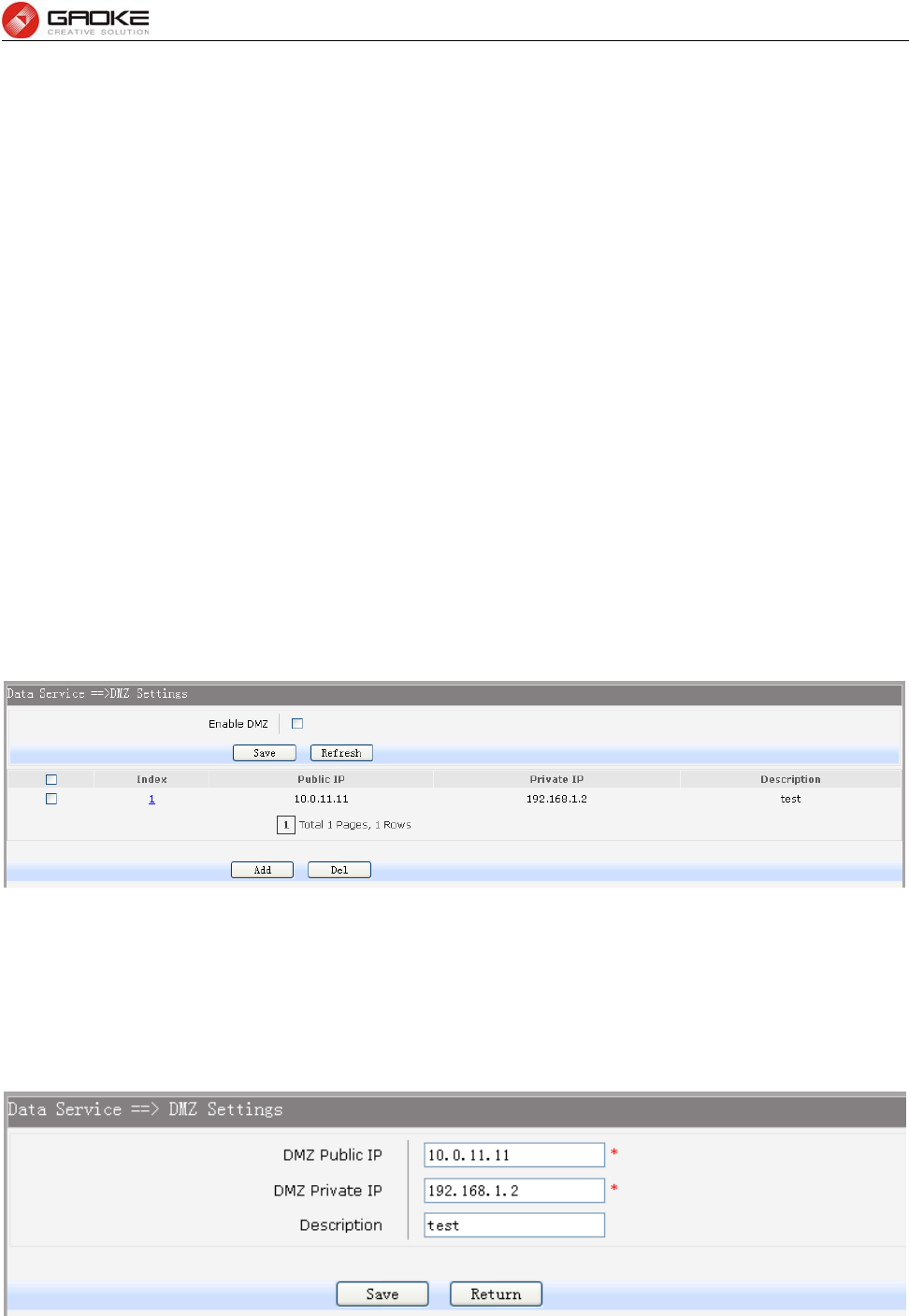
3.4.3.3 DMZ Settings
In computer security, a DMZ or Demilitarized Zone (sometimes referred to as a perimeter network) is a
physical or logical network that contains and exposes an organization's external-facing services to a
larger and insecure network, usually the Internet. The purpose of a DMZ is to add an additional layer of
security to an organization's local area network (LAN); an external attacker only has direct access to
equipment in the DMZ, rather than any other part of the network.
Choose the menu Data Service→NAT Config→DMZ Settings to load the following page.
Figure 3-42 View DMZ Settings
The following items are displayed on this screen:
► Enable DMZ: Enable or disable DMZ globally.
Click the Index in the entry you want to modify. If you want to delete the entry, select it and click the Del.
Click the Add button to add a new entry.
Figure 3-43 Add or Modify DMZ Entry
The following items are displayed on this screen:
► DMZ Public IP: The public IP address for this DMZ entry.
FG7008N User Manual
Page 34 of 111
► DMZ Private IP: The private IP address for this DMZ entry.
► Description: Enter a description string for this DMZ entry
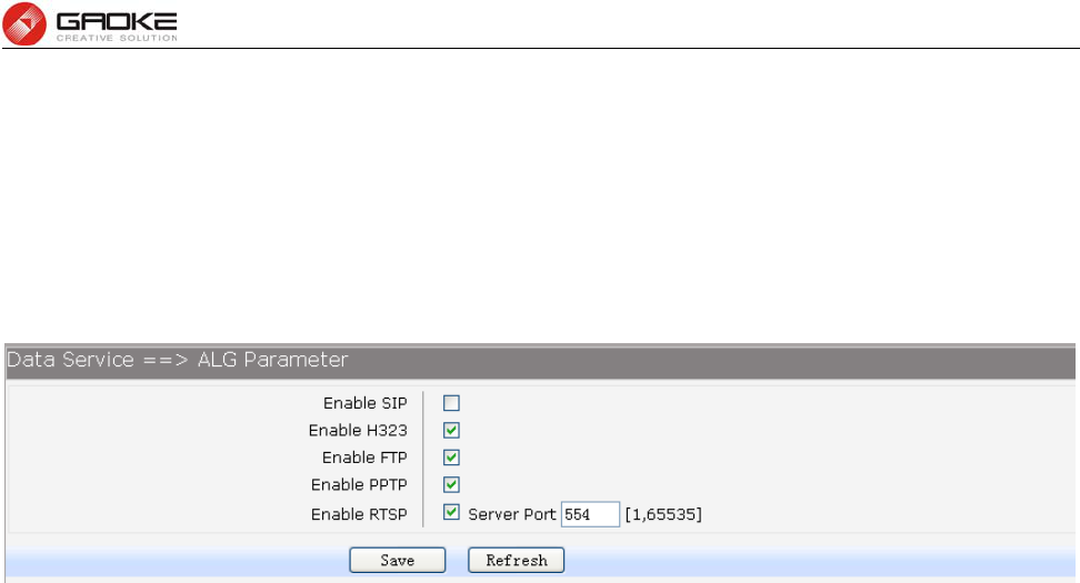
3.4.3.4 ALG Settings
Application Layer Gateway (ALG) allows customized Network Address Translation (NAT) traversal
filters to be plugged into the gateway to support address and port translation for certain application layer
"control/data" protocols such as FTP, H.323, PPTP, etc.
Choose the menu Data Service→NAT Config→ALG Settings to load the following page.
Figure 3-44 ALG Settings
The following items are displayed on this screen:
► Enable SIP: Enable or disable SIP ALG.
► Enable H323: Allow Microsoft NetMeeting clients to communicate across NAT if selected.
► Enable FTP: Allow FTP clients and servers to transfer data across NAT if selected.
► Enable PPTP: Enable or disable PPTP ALG.
► Enable RTSP: Enable or disable RTSP ALG.
3.4.4 Firewall Config
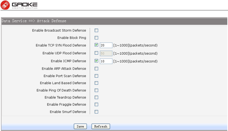
3.4.4.1 Attack Defense
With Attack Defense function enabled, the device can distinguish the malicious packets and prevent the
port scanning from external network, so as to guarantee the network security. Configure this for
abnormal packets defense and flood attack defense. Flood attack is a commonly used DoS (Denial of
Service) attack, including TCP SYN, UDP, ICMP, and so on.
Choose the menu Data Service→Firewall Config→Attack Defense to load the following page.
FG7008N User Manual
Page 35 of 111
Figure 3-45 Attack Defense
The following items are displayed on this screen:
► Enable Broadcast Storm Defense: Enable or disable Broadcast Storm Defense.
► Enable Block Ping: Enable or disable Block Ping function.
► Enable TCP SYN Flood Defense: Enable or disable TCP SYN Flood Defense.
► Enable UDP Flood Defense: Enable or disable UDP Flood Defense.
► Enable ICMP Defense: Enable or disable ICMP Defense.
► Enable ARP Attack Defense: Enable or disable ARP Attack Defense.
► Enable Port Scan Defense: A port scanner is a software application designed to probe a
server or host for open ports. Check the box to prevent port
scanning.
► Enable Land Based Defense: The Land Denial of Service attack works by sending a spoofed
packet with the SYN flag - used in a "handshake" between a
client and a host - set from a host to any port that is open and
listening. If the packet is programmed to have the same
destination and source IP address, when it is sent to a machine,
via IP spoofing, the transmission can fool the machine into
thinking it is sending itself a message, which, depending on the
operating system, will crash the machine. Check the box to
enable Land Based Defense.
► Enable Ping Of Death Defense: Ping of death is a denial of service (DoS) attack caused by an
attacker deliberately sending an IP packet larger than the
65,536 bytes allowed by the IP protocol. Check the box to
enable Ping of Death Defense.
► Enable Teardrop Defense: Teardrop is a program that sends IP fragments to a machine
connected to the Internet or a network. Check the box to enable
Teardrop Defense.
► Enable Fraggle Defense: A fraggle attack is a variation of a Smurf attack where an
attacker sends a large amount of UDP traffic to ports 7 (echo)
and 19 (chargen) to an IP Broadcast Address, with the
FG7008N User Manual
Page 36 of 111
intended victim's spoofed source IP address. Check the box to
enable Fraggle Defense.
► Enable Smurf Defense: The Smurf Attack is a denial-of-service attack in which large
numbers of Internet Control Message Protocol (ICMP) packets
with the intended victim's spoofed source IP are broadcast to a
computer network using an IP Broadcast address. Check the
box to enable Smurf Defense.
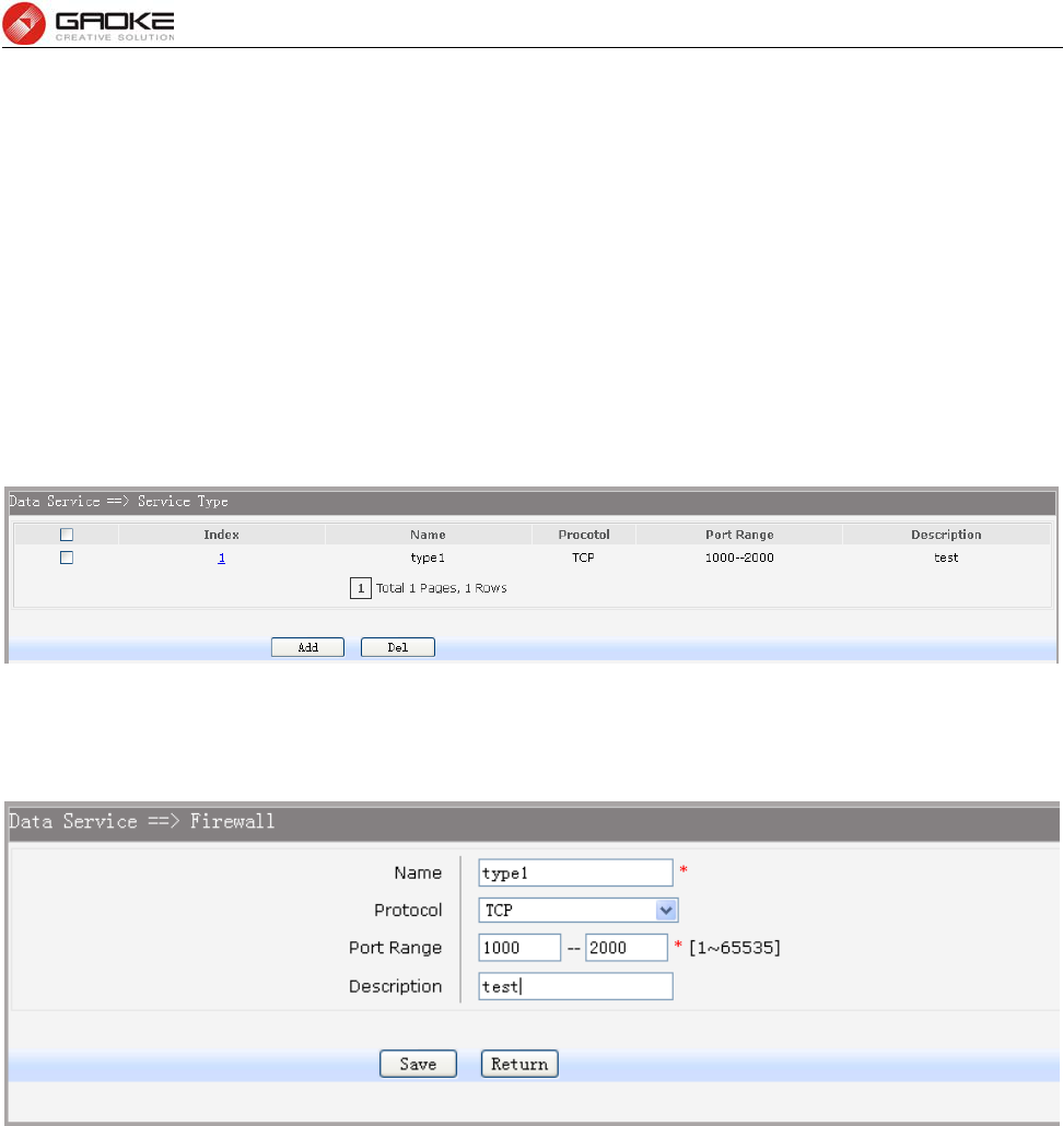
3.4.4.2 Service Type
Service Type defines the entry with protocol and port range, which can be chosen in Internet
Access-Ctrl page. Choose the menu Data Service→Firewall Config→Service Type to load the
following page.
Figure 3-46 View Service Type Configuration
Click the Index in the entry you want to modify. If you want to delete the entry, select it and click the Del.
Click the Add button to add a new entry.
Figure 3-47 Add or Modify Service Type Entry
The following items are displayed on this screen:
► Name: Name of this entry, it will be list in Internet Access-Ctrl page.
► Protocol: Select the protocol for this entry. Four types are provided: TCP, UDP, ICMP and ALL.
► Port Range: Configure the port range for this entry.
► Description: Enter a description string for this entry
3.4.4.3 Internet Access-Ctrl
Each sub-page under this page is used to control Internet access.
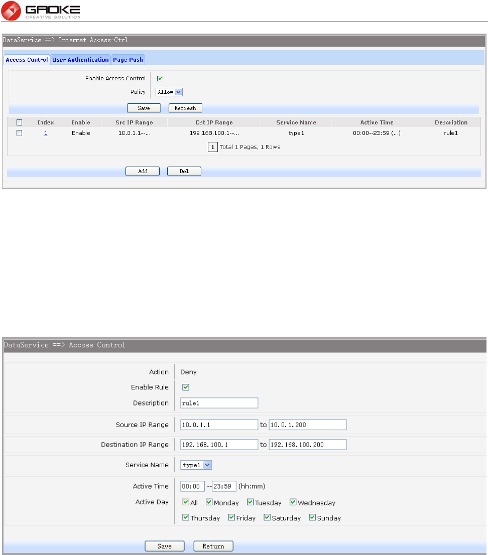
3.4.4.3.1 Access Control
This sub-page is used to control Internet access through IP, port, and time.
Choose the menu Data Service→Firewall Config→Internet Access-Ctrl→Access Control to load the
following page.
FG7008N User Manual
Page 37 of 111
Figure 3-48 View Access Control Entry
The following items are displayed on this screen:
► Enable Access Control: Enable or disable access control from WAN.
► Policy: Default policy of access control: Allow or Deny. If Allow is selected, all
packets will be allowed except the entries list on this page. If Deny is
selected, all packets will be denied except the entries list on this page.
Click the Index in the entry you want to modify. If you want to delete the entry, select it and click the Del.
Click the Add button to add a new entry.
Figure 3-49 Add or Modify Access Control Entry
The following items are displayed on this screen:
► Action: The policy of this entry, Allow or Deny. It is the inverse of Policy. Read only.
► Enable Rule: Enable or disable this rule.
► Description: Enter a description string for this rule
► Source IP Range: Enter the source IP range in dotted-decimal format (e.g. 192.168.1.23).
► Destination IP Range: Enter the destination IP range in dotted-decimal format (e.g. 192.168.1.23).
► Service Name: Choose a service type that defined in Service Type page.
► Active Time: Specify the time range for the entry to take effect.
► Active Day: Specify the day range for the entry to take effect.
FG7008N User Manual
Page 38 of 111
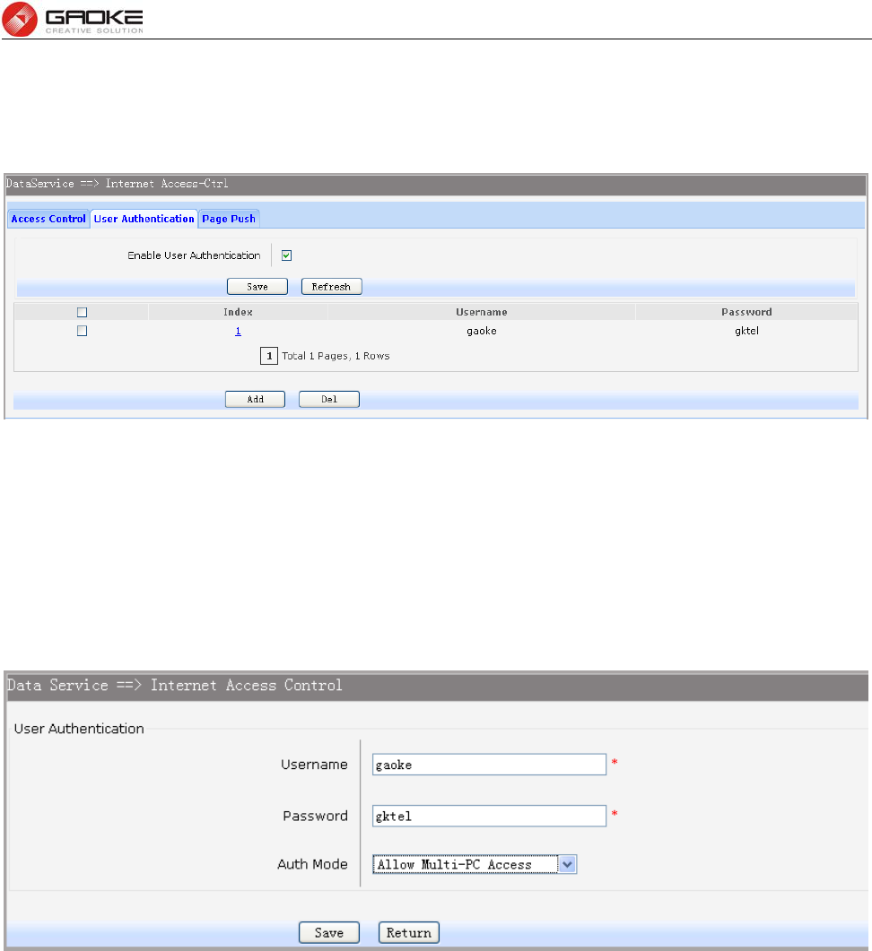
3.4.4.3.2 User Authentication
This sub-page is used to control Internet access through username and password.
Choose the menu Data Service→Firewall Config→Internet Access-Ctrl→User Authentication to
load the following page.
Figure 3-50 View User Authentication Entry
The following items are displayed on this screen:
► Enable User Authentication: Enable or disable user authentication globally. If enabled, only the
following list of users and passwords can access the Internet. Press Save button if you have modified
this parameter.
Click the Index in the entry you want to modify. If you want to delete the entry, select it and click the Del.
Click the Add button to add a new entry.
Figure 3-51 Add or Modify User Authentication Entry
The following items are displayed on this screen:
► Username: Enter the username of this entry.
► Password: Enter the password of this entry.
► Auth Mode: Choose the authentication mode of this entry. Provides four modes:
Allow Multi-PC Access: Allows multiple computers to access the Internet using this
account.
Allow One PC Access: Only allows one computer to access the Internet using this
account.
Allow Special IP Access: Allowing only specified IP computer uses this account to
access the Internet.
Allow Special MAC Access: Allowing only specified MAC computer uses this account
to access the Internet
FG7008N User Manual
Page 39 of 111
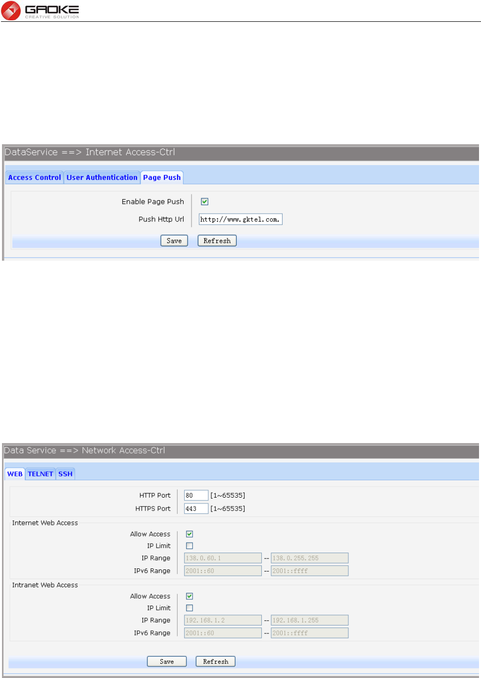
3.4.4.3.3 Page Push
HTTP Page push is a mechanism for sending unsolicited (asynchronous) data from web server to a web
browser. When accessing the Internet for the first time, the specified HTTP page will be pushed to the
browser when enabled.
Choose the menu Data Service→Firewall Config→Internet Access-Ctrl→Page Push to load the
following page.
Figure 3-52 Configure Page Push
The following items are displayed on this screen:
► Enable Page Push: If enabled, push specified HTTP page to the browser when accessing the
Internet for the first time.
► Push Http Url: Specifies the HTTP URL of the page you want to push.
3.4.4.4 Network Access-Ctrl
3.4.4.4.1 WEB
Choose the menu Data Service→Firewall Config→Netword Access-Ctrl→WEB to load the following
page.
Figure 3-53 Configure WEB Access-Ctrl
The following items are displayed on this screen:
► HTTP Port: Port used with HTTP access device.
HTTP: Hypertext Transfer Protocol.
FG7008N User Manual
Page 40 of 111
► HTTPS Port: Port used with HTTPS access device.
HTTPS: it is the result of simply layering the Hypertext Transfer Protocol (HTTP) on
top of the SSL/TLS protocol.
Internet Web Access:
► Allow Access: If enabled, allow user to access the device from the Internet via WEB.
► IP Limit: If enabled, allow only specific IP range to access the device from the Internet via
WEB.
► IP Range: If IP Limit enabled, specifies the IPv4 address range that is only allowed to access
to the device from the Internet via WEB.
► IPv6 Range: If IP Limit enabled, specifies the IPv6 address range that is only allowed to access to
the device from the Internet via WEB.
Intranet Web Access:
► Allow Access: If enabled, allow user to access the device from the Intranet via WEB.
► IP Limit: If enabled, allow only specific IP range to access the device from the Intranet via
WEB.
► IP Range: If IP Limit enabled, specifies the IPv4 address range that is only allowed to access
the device from the Intranet via WEB.
► IPv6 Range: If IP Limit enabled, specifies the IPv6 address range that is only allowed to access
the device from the Intranet via WEB.
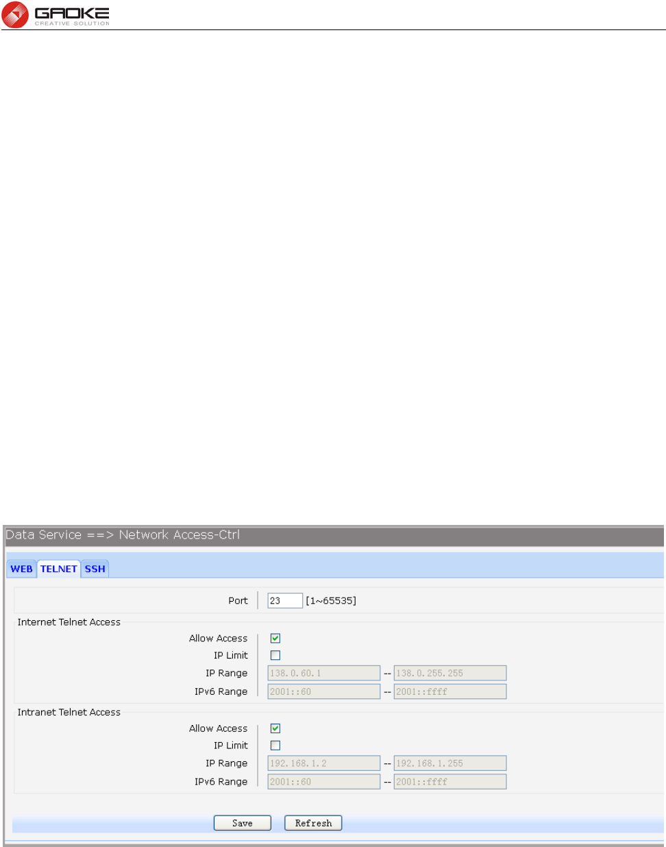
3.4.4.4.2 TELNET
Choose the menu Data Service→Firewall Config→Netword Access-Ctrl→TELNET to load the
following page.
Figure 3-54 Configure Telnet Access-Ctrl
The following items are displayed on this screen:
► Port: Port when using telnet tools access device.
Internet Web Access:
► Allow Access: If enabled, allow access to the device from the Internet via telnet.
► IP Limit: If enabled, allow only specific IP range to access the device from the Internet via
telnet
► IP Range: If IP Limit enabled, specifies the IPv4 address range that only allow access to the
FG7008N User Manual
Page 41 of 111
device from the Internet via telnet.
► IPv6 Range: If IP Limit enabled, specifies the IPv6 address range that only allow access to the
device from the Internet via telnet.
Intranet Web Access:
► Allow Access: If enabled, allow access to the device from the Intranet via telnet.
► IP Limit: If enabled, allow only specific IP range to access the device from the Intranet via
telnet
► IP Range: If IP Limit enabled, specifies the IPv4 address range that only allow access to the
device from the Intranet via telnet.
► IPv6 Range: If IP Limit enabled, specifies the IPv6 address range that only allow access to the
device from the Intranet via telnet.
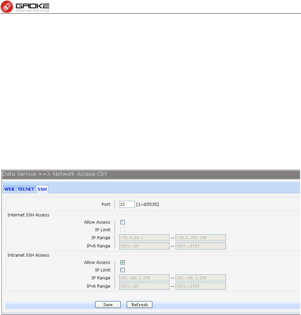
3.4.4.4.3 SSH
Choose the menu Data Service→Firewall Config→Netword Access-Ctrl→SSH to load the following
page.
Figure 3-55 Configure SSH Access-Ctrl
The following items are displayed on this screen:
► Port: Port when using SSH tools access device.
Internet Web Access:
► Allow Access: If enabled, allow access to the device from the Internet via SSH.
► IP Limit: If enabled, allow only specific IP range to access the device from the Internet via
SSH
► IP Range: If IP Limit enabled, specifies the IPv4 address range that only allow access to the
device from the Internet via SSH.
► IPv6 Range: If IP Limit enabled, specifies the IPv6 address range that only allow access to the
device from the Internet via SSH.
Intranet Web Access:
► Allow Access: If enabled, allow access to the device from the Intranet via SSH.
► IP Limit: If enabled, allow only specific IP range to access the device from the Intranet via
SSH
FG7008N User Manual
Page 42 of 111
► IP Range: If IP Limit enabled, specifies the IPv4 address range that only allow access to the
device from the Intranet via SSH.
► IPv6 Range: If IP Limit enabled, specifies the IPv6 address range that only allow access to the
device from the Intranet via SSH.
3.4.4.5 Filter Strategy
Each sub-page under this page is used to filter Internet access.
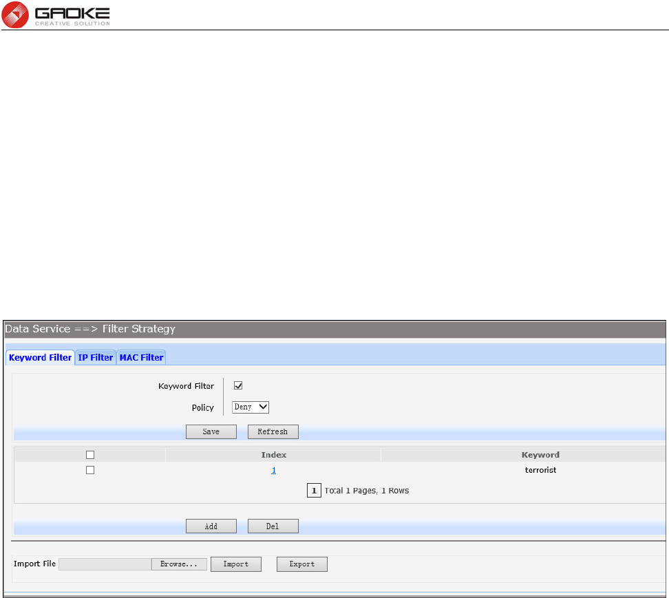
3.4.4.5.1 Keyword Filter
Choose the menu Data Service→Firewall Config→Filter Strategy→Keyword Filter to load the
following page.
Click the Index in the entry you want to modify. If you want to delete the entry, select it and click the Del.
Click the Add button to add a new entry.
Figure 3-56 Configure Keyword Filter
The following items are displayed on this screen:
► Keyword Filter: If enabled, packet filtering is enabled by keyword.
► Policy: The policy for filtering web page, Deny and Allow.
You can export all the keywords as a file. Of course, you can also import a file.
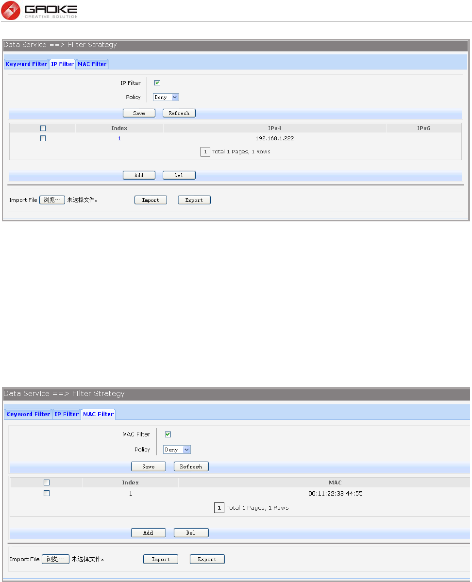
3.4.4.5.2 IP Filter
On this page, you can control the Internet access of local hosts by specifying their IP addresses.
Choose the menu Data Service→Firewall Config→Filter Strategy→IP Filter to load the following
page.
Click the Index in the entry you want to modify. If you want to delete the entry, select it and click the Del.
Click the Add button to add a new entry.
FG7008N User Manual
Page 43 of 111
Figure 3-57 Configure IP Filter
The following items are displayed on this screen:
► IP Filter: If enabled, packet filtering is enabled by IP address.
► Policy: The policy for IP address list. Deny and Allow.
You can export all the IP addresses as a file. Of course, you can also import a file.
3.4.4.5.3 MAC Filter
On this page, you can control the Internet access of local hosts by specifying their MAC addresses.
Choose the menu Data Service→Firewall Config→Filter Strategy→MAC Filter to load the following
page.
Figure 3-58 Configure MAC Filter
The following items are displayed on this screen:
► IP Filter: If enabled, packet filtering is enabled by MAC.
► Policy: The policy for MAC list. Deny and Allow.
You can export all the MAC addresses as a file. Of course, you can also import a file.
If you want to delete an entry, select it and click the Del. Click the Add button to add a new entry.
There are two ways to add MAC:
Artificial designated MAC: You can manually enter a MAC.
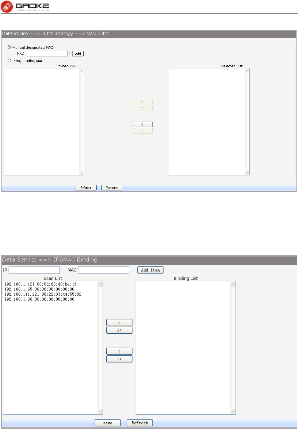
FG7008N User Manual
Page 44 of 111
Using Studying MAC: You can choose one or more MAC devices learned.
Figure 3-59 Add a MAC Filter Entry
3.4.4.6 IP&MAC Binding
Choose the menu Data Service→Firewall Config→IP&MAC Binding to load the following page.
There are two ways to add a binding entry: You can manually enter a pair of IP and MAC, and then press
Add Item. Alternatively you can select a pair of IP and MAC in Scan List that device learned.
Figure 3-60 Configure IP&MAC Binding
FG7008N User Manual
Page 45 of 111
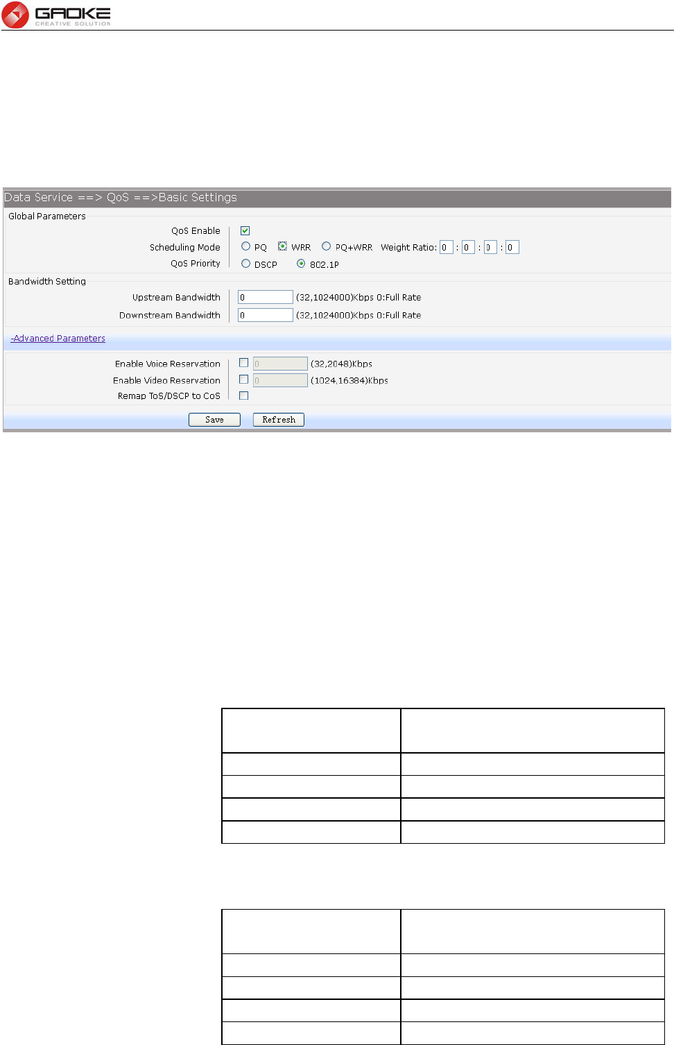
3.4.5 QoS
3.4.5.1 Basic Settings
QOS feature is enabled by default, based on 802.1P, strict priority scheduling mode. The device
supports four priority queues, when QOS feature enabled.
Choose the menu Data Service→QoS→Basic Settings to load the following page.
Figure 3-61 Configure QoS Basic Settings
The following items are displayed on this screen:
Global Parameters
► Qos Enable: Enable or disable QoS functionality.
► Scheduling Mode: PQ: PQ means strict priority, that is, when congestion occurs, first
sending packets of high priority queue.
WRR: All queues use weighted fair queuing scheme which is defined in
Weight Ratio
PQ+WRR: Only highest queue use strict priority; others use weighted
fair queuing scheme.
► Qos Priority: DSCP: When you select DSCP value, corresponding to the following
relationship.
DSCP priority value Priority queue (queue 3 highest
priority)
0-15 Queue 0
16 ~ 31 Queue 1
32 to 47 Queue 2
48 ~ 63 Queue 3
802.1P: Select the queue classification mode, when selecting 802.1P
mode, depending on the value of 802.1p priority classification into
different queues, corresponding to the following relationship.
801.1p priority value Priority queue (queue 3 highest
priority)
0 to 1 Queue 0
2.3 Queue 1
4.5 Queue 2
6-7 Queue 3
FG7008N User Manual
Page 46 of 111
Bandwidth Setting
► Upstream Bandwidth: Configure the bandwidth of upstream.
► Downstream Bandwidth: Configure the bandwidth of downstream.
Advanced Parameters
► Enable Voice Reservation: Enable voice reservation and give the value to reserved for voice
► Enable Video Reservation: Enable video reservation and give the value to reserved for video
► Remap Tos/DSCP to CoS: Check the box that the system will remark 802.1P value with
TOS/DSCP of upstream packets, the mapping relationship is as
follows:
DSCP priority value 802.1p priority
0-7 0
8-15 1
16 ~ 23 2
24 ~ 31 3
32 to 39 4
40 ~ 47 5
48 ~ 55 6
56 to 63 7
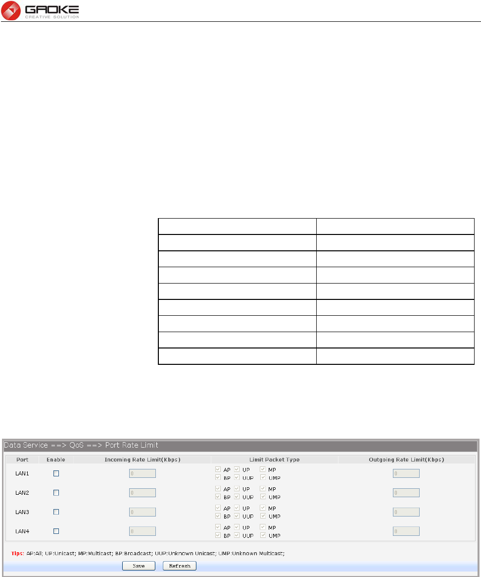
3.4.5.2 Port Rate Limit
Rate limit for physical LAN ports, you can select the package type restrictions limiting the entrance. All
multiples of 32kbps speed requirements
Choose the menu Data Service→QoS→Port Rate Limit to load the following page.
Figure 3-62 Configure Qos Port Rate Limit
The following items are displayed on this screen:
► Port: Physical LAN port
► Enable: Enable or disable rate limit function.
► Incoming Rate Limit: Enter incoming maximum rate, which must is times of 32Kbsp.
►Limit Packet Type: Select the packet type which is limited rate.
► Outgoing Rate Limit: Enter Outgoing maximum rate, which must is times of 32Kbsp.
3.4.5.3 Flow Rate Limit
Choose the menu Data Service→QoS→Flow Rate Limit to load the following page.
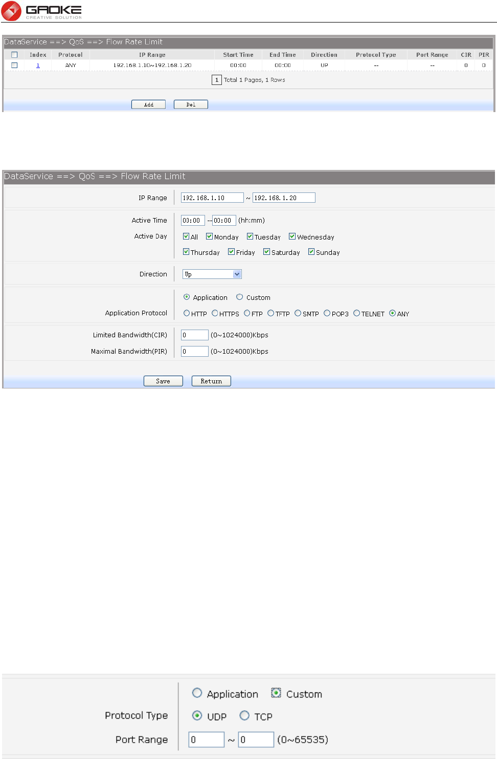
FG7008N User Manual
Page 47 of 111
Figure 3-63 View QoS Flow Rate Limit Entry
Click the Index in the entry you want to modify. If you want to delete the entry, select it and click the Del.
Click the Add button to add a new entry.
Figure 3-64 Configure Qos Flow Rate Limit
The following items are displayed on this screen:
► IP Range: The IP range of LAN’s PC.
► Active Time: If not configured, which means that all time are in active
► Active Day: If not configured, which means that all time in active
► Direction: Up: Check the frame from the direction of the LAN port to the WAN port,
and match the source IP and destination port;
Down: Check the frame from the direction of the WAN port to the LAN
port, and match the destination IP and source port;
Bidirectional: Limit both upstream and downstream speed.
► Limited Bandwidth(CIR): The limited bandwidth.
► Maximal Bandwidth(PIR): The maximum bandwidth.
If Application is selected:
► Application Protocol: Such as HTTP, HTTPS, FTP, TFTP, SMTP, POP3, TELNET, etc.
If Custom is selected, the following page will be loaded:
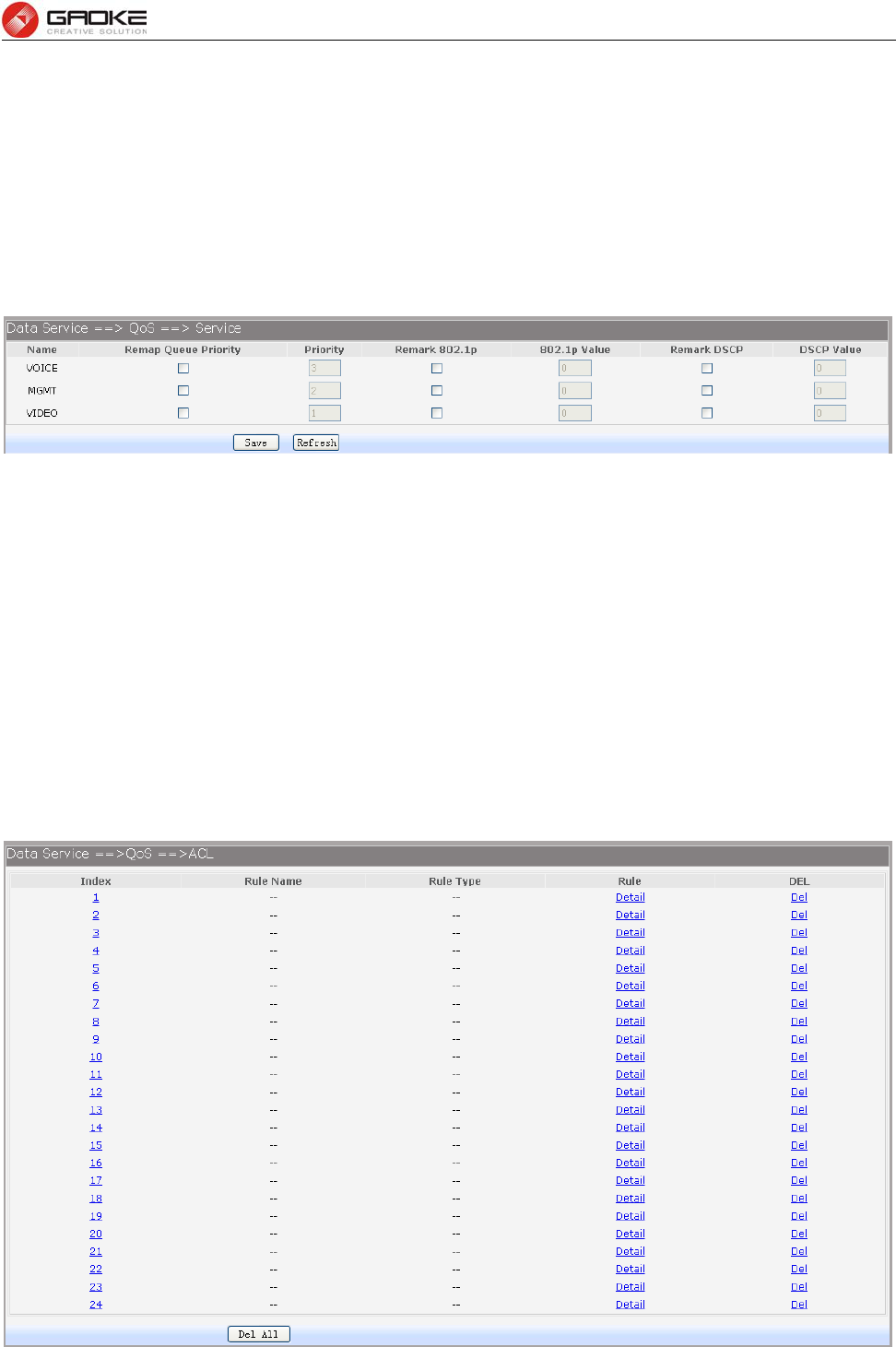
FG7008N User Manual
Page 48 of 111
Figure 3-65 Configure Custom of Qos Flow Rate Limit
The following items are displayed on this screen:
► Protocol Type: Custom protocol type, UDP or TCP.
► Port Range: Set port range.
3.4.5.4 Service
The device supports to remap scheduling priority and remark the value of DSCP or 802.1P according to
the service type.
Choose the menu Data Service→QoS→Service to load the following page.
Figure 3-66 View Qos Service
The following items are displayed on this screen:
► Name: Service name. Read only.
► Remap Queue Priority: Check the box to remap scheduling queue.
► Priority: There are four levels of priority. Priority 3 is highest, and priority 0 is the
lowest
► Remark 802.1p: Check the box to enable 802.1p priority remarking.
► 802.1p Value: The value of remarking 802.1P.
► Remark DSCP: Check the box to enable DSCP remarking.
► DSCP Value: The value of remarking DSCP.
3.4.5.5 ACL
Choose the menu Data Service→QoS→ACL to load the following page.
Figure 3-67 View Qos ACL

FG7008N User Manual
Page 49 of 111
Click the Del in the entry you want to delete.
Click the Index or Detail in the entry you want to modify, and then the following page will be loaded:
Figure 3-68 Modify Qos ACL
The following items are display on this page:
Condition:
► Rule Name: The custom name.
► Physical Port: Rule’s source port
► Rule Type: Type of rule: L2 data or L3 data.
If L3 Data is selected:
Figure 3-69 L3 Data Rule Type
The following items are display on this page:
► Src IP/Netmask: The source IP address and netmask of packets, such is
192.168.100.1/255.255.255.0.
► Dest IP/Netmask: The destination IP address and netmask of packets.
► Protocol: E.g. ICMP, UDP, TCP, or custom IP protocol types.
► L4 Src Port: Source port range.
► L4 Dest Port: Destination port range.
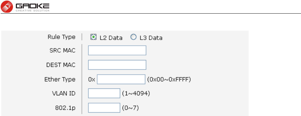
FG7008N User Manual
Page 50 of 111
If L2 Data is selected:
Figure 3-70 L2 Data Rule Type
The following items are display on this page:
► SRC MAC: Source MAC address of packets.
► DEST MAC: Destination MAC address of packets.
► Ether Type: The ether type of packets.
► VLAN ID: The VLAN id of packets.
► 802.1p: The VLAN priority of packets.
Action
► Drop: Drop the packets matched with the rule.
► Remark VID: Change the VID of packets matched with the rule.
► Remark 802.1p: Change the 802.1P priority of packets matched with the rule.
► Remark DSCP: Change the DSCP of packets matched with the rule.
► Priority: Change the scheduling queue of packets matched with the rule.
► Maximal Bandwidth: Limit the bandwidth of packet matched with the rule.
3.4.6 DDNS
DDNS(Dynamic DNS) service allows you to assign a fixed domain name to a dynamic WAN ip address,
which enables the Internet hosts to access the Router or the hosts in LAN using the domain names.
Choose the menu Data Service→DDNS to load the following page.
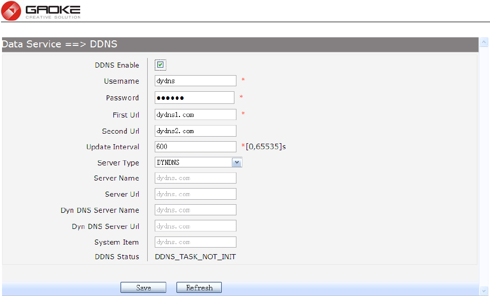
FG7008N User Manual
Page 51 of 111
Figure 3-71 Configure DDNS
The following items are display on this page:
► DDNS Enable: Active or inactive dynamic DNS service.
► Username: Enter account name of your DDNS account.
► Password: Enter password of your DDNS account.
► First Url: First domain name that you registered your DDNS service provider.
► Second Url: First domain name that you registered your DDNS service provider.
► Update Interval: How often, in seconds, the IP is updated.
► Server Type: optional DDNS server type, can select from pull-dwon list:
DYNDNS: For dyndns.org
FREEDNS: For freedns.afraid.org
ZONE: For zoneedit.com
NOIP: For no-ip.com
3322: For 3322.org
CUSTOM: For custom self-defined DDNS server type.
► Server Name: If CUSTOM is selected, specify server name of the device.
► Server Url: If CUSTOM is selected, specify server URL of the device.
► Dyn DNS Server Name: If CUSTOM is selected, specify dyndns DNS server name of custom
self-defined.
► Dyn DNS Server Url: If CUSTOM is selected, specify dyndns DNS server URL of custom
self-defined.
► System Item: If CUSTOM is selected, specify system item of custom self-defined.
► DDNS Status: Display the status of DDNS service. Read only.
Click the Save button when finished.
Click Refresh button to refresh the web page.
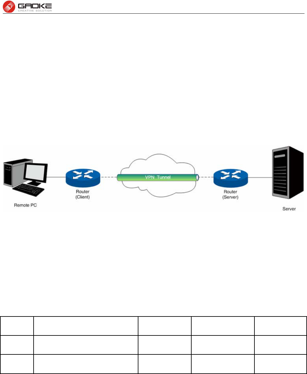
FG7008N User Manual
Page 52 of 111
3.4.7 VPN
VPN (Virtual Private Network) is a private network established via the public network, generally via the
Internet. However, the private network is a logical network without any physical network lines, so it is
called Virtual Private Network.
With the wide application of the Internet, more and more data are needed to be shared through the
Internet. Connecting the local network to the Internet directly, though can allow the data exchange, will
cause the private data to be exposed to all the users on the Internet. The VPN (Virtual Private Network)
technology is developed and used to establish the private network through the public network, which can
guarantee a secured data exchange.
VPN adopts the tunneling technology to establish a private connection between two endpoints. It is a
connection secured by encrypting the data and using point-to-point authentication. The following
diagram is a typical VPN topology.
Figure 3-72 VPN – Network Topology
As the packets are encapsulated and de-encapsulated in the Router, the tunneling topology
implemented by encapsulating packets is transparent to users. The tunneling protocols supported
contain Layer 3 IPSEC and Layer 2 L2TP/PPTP.
3.4.7.2 PPTP Server
Layer 2 VPN tunneling protocol consists of L2TP (Layer 2 Tunneling Protocol) and PPTP (Point to Point
Tunneling Protocol).Both L2TP and PPTP encapsulate packet and add extra header to the packet by
using PPP (Point to Point Protocol).
Table depicts the difference between L2TP and PPTP.
Protocol Media Tunnel Length of Header Authentication
PPTP IP network Single tunnel 6 bytes at least Not supported
L2TP IP network of UDP Multiple tunnels 4 bytes at least Supported
Figure 3-73 Difference between L2TP and PPTP
Choose the menu Data Service→VPN→PPTP Server to load the following page.
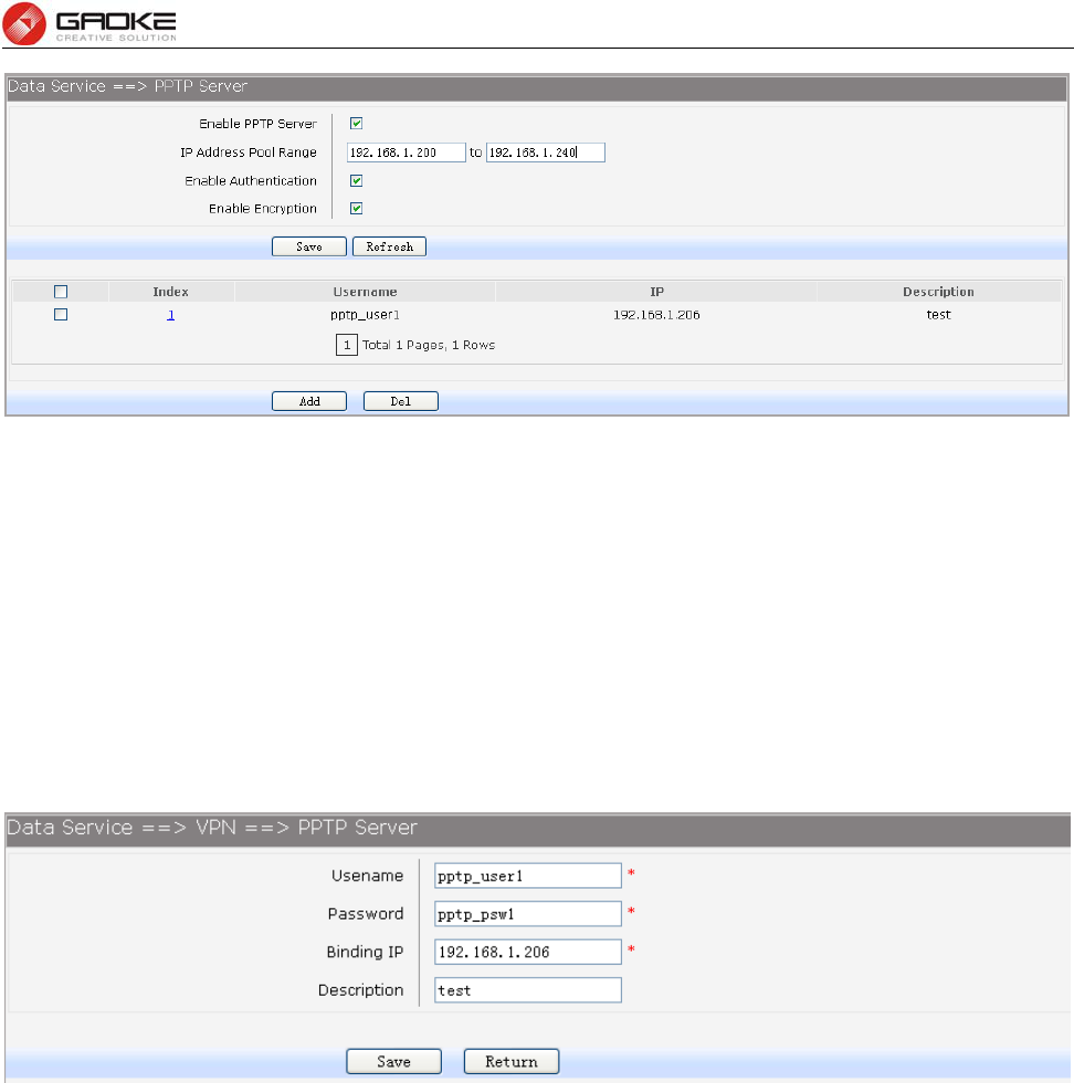
FG7008N User Manual
Page 53 of 111
Figure 3-74 Configure PPTP Server
The following items are displayed on this screen:
► Enable PPTP Server: Enable or disable the PPTP server function globally.
► IP Address Pool Range: Specify the start and the end IP address for IP Pool. The start IP address
should not exceed the end address and the IP ranges must not overlap.
► Enable Authentication: Specify whether to enable authentication for the tunnel.
► Enable Encryption: Specify whether to enable the encryption for the tunnel. If enabled, the
PPTP tunnel will be encrypted by MPPE.
Click the Index in the entry you want to modify. If you want to delete the entry, select it and click the Del.
Click the Add button to add a new entry.
Figure 3-75 Add or Modify PPTP Client Entry
The following items are displayed on this screen:
► Username: Enter the account name of PPTP tunnel. It should be configured identically on server
and client.
► Password: Enter the password of PPTP tunnel. It should be configured identically on server and
client.
► Binding IP: Enter the IP address of the client which is allowed to connect to this PPTP server.
► Description: Enter the humane readable description for this account.
3.4.7.3 L2TP Server
Choose the menu Data Service→VPN→L2TP Server to load the following page.
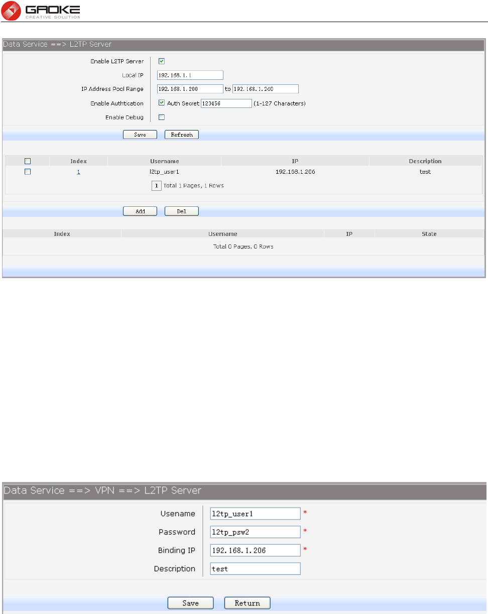
FG7008N User Manual
Page 54 of 111
Figure 3-76 Configure L2TP Server
The following items are displayed on this screen:
► Enable L2TP Server: Enable or disable the L2TP server function globally.
► Local IP: Enter the local IP address of L2TP server.
► IP Address Pool Range: Specify the start and the end IP address for IP Pool. The start IP address
should not exceed the end address and the IP ranges must not overlap.
► Enable Authentication: Specify whether to enable authentication for the tunnel. If enabled, enter
the authentication secret.
► Enable Debug: Specify whether to enable the debug for L2TP.
Click the Index in the entry you want to modify. If you want to delete the entry, select it and click the Del.
Click the Add button to add a new entry.
Figure 3-77 Add or Modify L2TP Client Entry
The following items are displayed on this screen:
► Username: Enter the account name of L2TP tunnel. It should be configured identically on server
and client.
► Password: Enter the password of L2TP tunnel. It should be configured identically on server and
client.
► Binding IP: Enter the IP address of the client which is allowed to connect to this L2TP server.
► Description: Enter the humane readable description for this account.
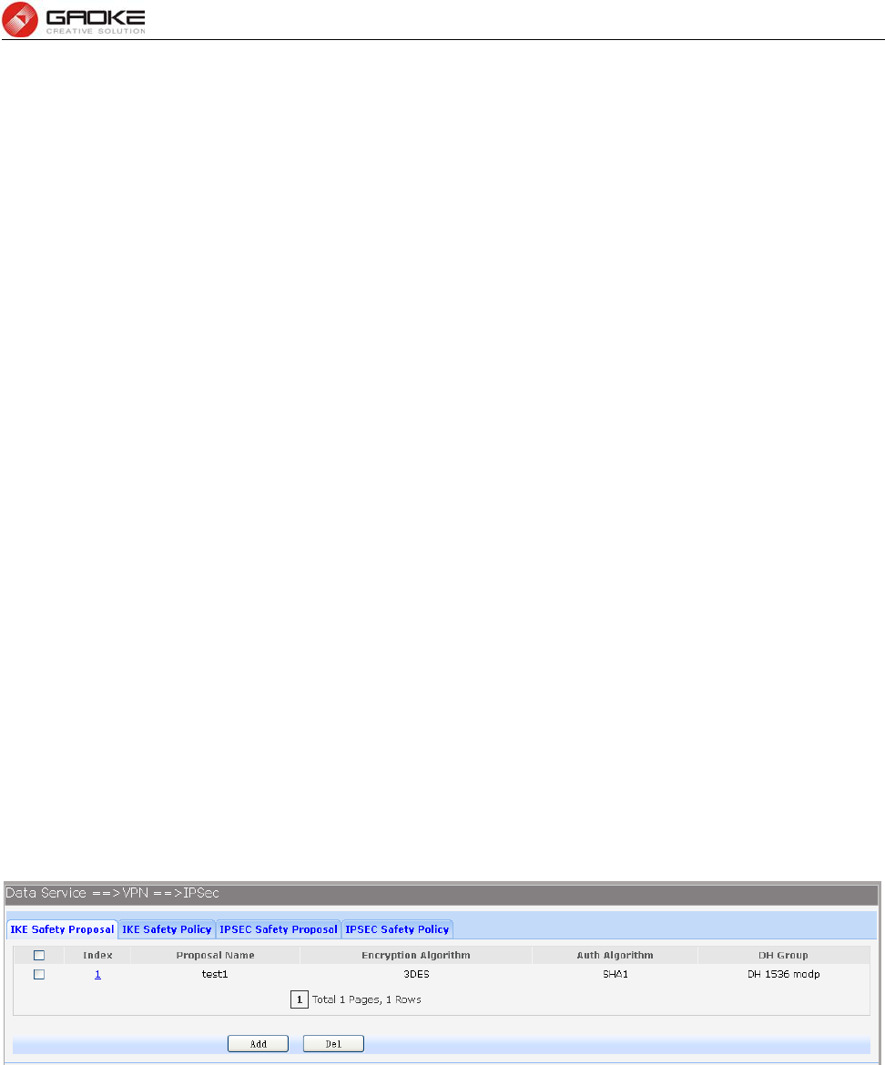
FG7008N User Manual
Page 55 of 111
3.4.7.4 IPSEC
IPSEC (IP Security) is a set of services and protocols defined by IETF (Internet Engineering Task Force)
to provide high security for IP packets and prevent attacks. To ensure a secured communication, the two
IPSEC peers use IPSEC protocol to negotiate the data encryption algorithm and the security protocols
for checking the integrity of the transmission data, and exchange the key to data de-encryption. IPSEC
has two important security protocols, AH (Authentication Header) and ESP (Encapsulating Security
Payload). AH is used to guarantee the data integrity. If the packet has been tampered during
transmission, the receiver will drop this packet when validating the data integrity. ESP is used to check
the data integrity and encrypt the packets. Even if the encrypted packet is intercepted, the third party still
cannot get the actual information.
IKE: In the IPSEC VPN, to ensure a secure communication, the two peers should encapsulate and
de-encapsulate the packets using the information both known. Therefore the two peers need to
negotiate a security key for communication with IKE (Internet Key Exchange) protocols. Actually IKE is a
hybrid protocol based on three underlying security protocols, ISAKMP (Internet Security Association and
Key Management Protocol), Oakley Key Determination Protocol, and SKEME Security Key Exchange
Protocol. ISAKMP provides a framework for Key Exchange and SA (Security Association) negotiation.
Oakley describes a series of key exchange modes. SKEME describes another key exchange mode
different from those described by Oakley. IKE consists of two phases. Phase 1 is used to negotiate the
parameters, key exchange algorithm and encryption to establish an ISAKMP SA for securely exchanging
more information in Phase 2. During phase 2, the IKE peers use the ISAKMP SA established in Phase 1
to negotiate the parameters for security protocols in IPSEC and create IPSEC SA to secure the
transmission data.
3.4.7.4.1 IKE Safety Proposal
In this table, you can view the information of IKE Proposals.
Choose the menu Data Service→VPN→IPSec→IKE Safety Proposal to load the following page.
Figure 3-78 View IKE Safety Proposal Configuration
Click the Index in the entry you want to modify. If you want to delete the entry, select it and click the Del.
Click the Add button to add a new entry.
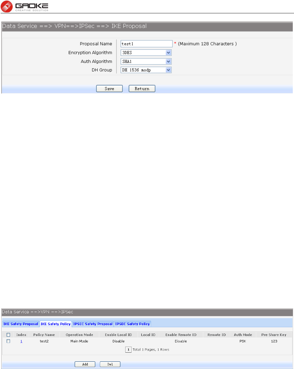
FG7008N User Manual
Page 56 of 111
Figure 3-79 Add or Modify IKE Safety Proposal Entry
The following items are displayed on this screen:
► Proposal Name: Specify a unique name to the IKE proposal for identification and management
purposes. The IKE proposal can be applied to IPSEC proposal.
► Encryption Algorithm: Specify the encryption algorithm for IKE negotiation. Options include:
DES: DES (Data Encryption Standard) encrypts a 64-bit block of plain text
with a 56-bit key.
3DES: Triple DES, encrypts a plain text with 168-bit key.
AES: Uses the AES algorithm for encryption.
► Auth Algorithm: Select the authentication algorithm for IKE negotiation. Options include:
MD5: MD5 (Message Digest Algorithm) takes a message of arbitrary length
and generates a 128-bit message digest.
SHA1: SHA1 (Secure Hash Algorithm) takes a message less than 2^64 (the
64th power of 2) in bits and generates a 160-bit message digest.
► DH Group: Select the DH (Diffie-Hellman) group to be used in key negotiation phase 1.
The DH Group sets the strength of the algorithm in bits. Options include DH
768 modp, DH 1024 modp and DH 1536 modp.
3.4.7.4.2 IKE Safety Policy
In this table, you can view the information of IKE Policy.
Choose the menu Data Service→VPN→IPSec→IKE Safety Policy to load the following page.
Figure 3-80 View IKE Safety Policy Configuration
Click the Index in the entry you want to modify. If you want to delete the entry, select it and click the Del.
Click the Add button to add a new entry.
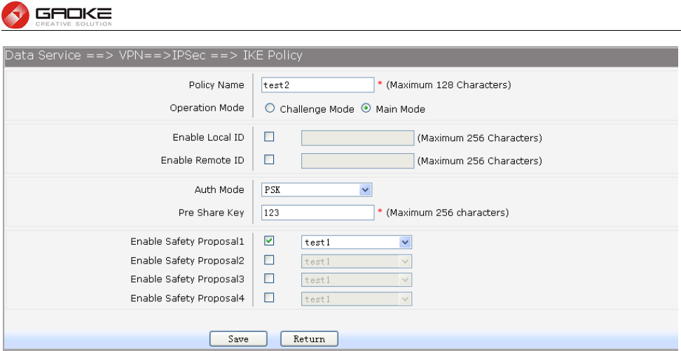
FG7008N User Manual
Page 57 of 111
Figure 3-81 Add or Modify IKE Safety Policy Entry
The following items are displayed on this screen:
► Policy Name: Specify a unique name to the IKE policy for identification and management
purposes. The IKE policy can be applied to IPSEC policy.
► Operation Mode: Select the IKE Exchange Mode in phase 1, and ensure the remote VPN
peer uses the same mode.
Main: Main mode provides identity protection and exchanges more
information, which applies to the scenarios with higher requirement for
identity protection.
Challenge: Challenge Mode establishes a faster connection but with lower
security, which applies to scenarios with lower requirement for identity
protection.
► Enable Local ID: If enabled, enter a name for the local device as the ID in IKE negotiation.
► Enable Remote ID: If enabled, enter the name of the remote peer as the ID in IKE negotiation.
► Auth Mode: Select the authentication mode for this IKE policy entry.
PSK:
Certificate:
► Pre Share Key: Enter the Pre-shared Key for IKE authentication, and ensure both the two
peers use the same key. The key should consist of visible characters
without blank space.
► Enable Safety Proposal: Select the Proposal for IKE negotiation phase 1. Up to four proposals can
be selected.
3.4.7.4.3 IPSEC Safety Proposal
In this table, you can view the information of IPSEC proposal.
Choose the menu Data Service→VPN→IPSec→IPSEC Safety Proposal to load the following page.
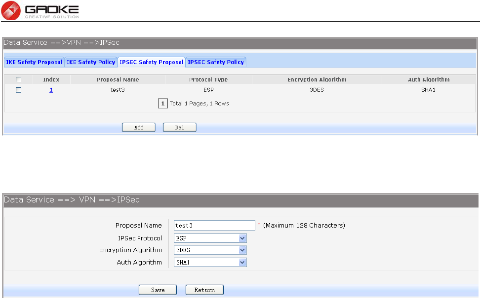
FG7008N User Manual
Page 58 of 111
Figure 3-82 View IPSEC Safety Proposal Configuration
Click the Index in the entry you want to modify. If you want to delete the entry, select it and click the Del.
Click the Add button to add a new entry.
Figure 3-83 Add or Modify IPSEC Safety Proposal Entry
The following items are displayed on this screen:
► Proposal Name: Specify a unique name to the IPSEC Proposal for identification and
management purposes. The IPSEC proposal can be applied to IPSEC
policy.
► IPSec Protocol: Select the security protocol to be used. Options include:
AH: AH (Authentication Header) provides data origin authentication, data
integrity and anti-replay services.
ESP: ESP (Encapsulating Security Payload) provides data encryption in
addition to origin authentication, data integrity, and anti-replay services.
ESP+AH: Both ESP and AH security protocol.
► Encryption Algorithm: Select the algorithm used to encrypt the data for ESP encryption. Options
include:
DES: DES (Data Encryption Standard) encrypts a 64-bit block of plain text
with a 56-bit key. The key should be 8 characters.
3DES: Triple DES, encrypts a plain text with 168-bit key. The key should
be 24 characters.
AES: Uses the AES algorithm for encryption. The key should be 16
characters.
► Auth Algorithm: Select the algorithm used to verify the integrity of the data. Options include:
MD5: MD5 (Message Digest Algorithm) takes a message of arbitrary
length and generates a 128-bit message digest.
SHA: SHA (Secure Hash Algorithm) takes a message less than the 64th
power of 2 in bits and generates a 160-bit message digest.
3.4.7.4.4 IPSEC Safety Policy
In this table, you can view the information of IPSEC policy.
Choose the menu Data Service→VPN→IPSec→IPSEC Safety Policy to load the following page.
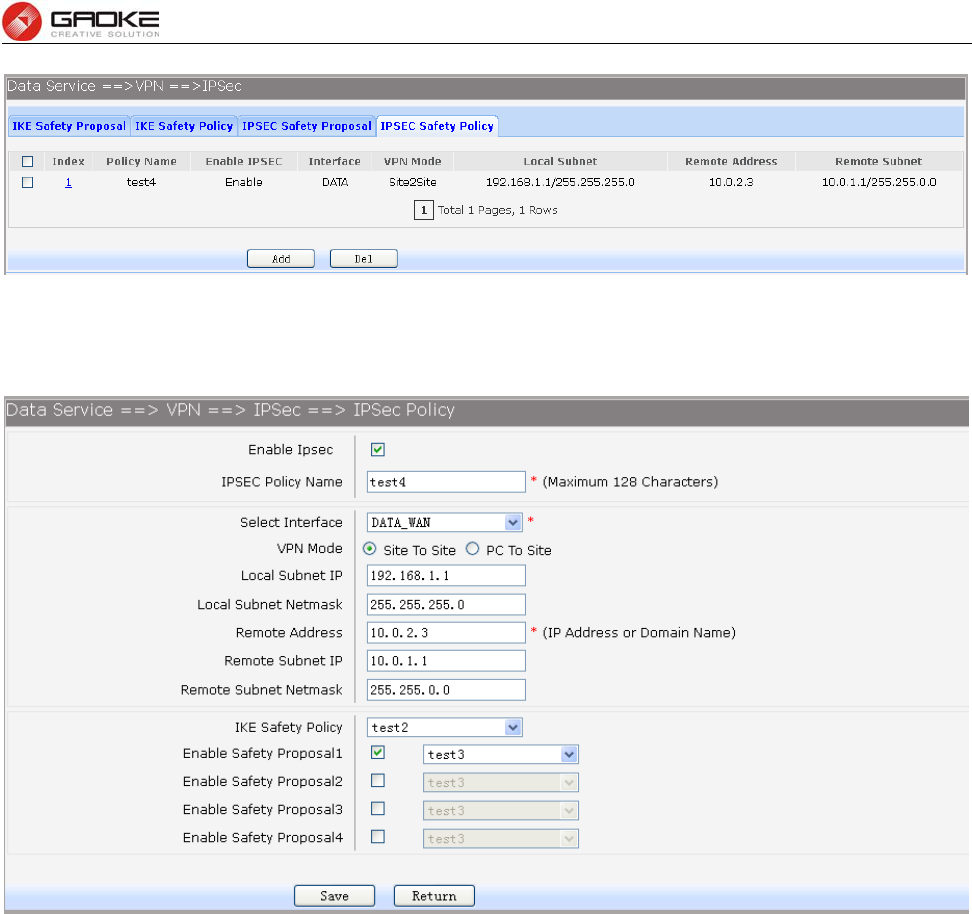
FG7008N User Manual
Page 59 of 111
Figure 3-84 View IPSEC Safety Policy Configuration
Click the Index in the entry you want to modify. If you want to delete the entry, select it and click the Del.
Click the Add button to add a new entry.
Figure 3-85 Add or Modify IPSEC Safety Policy Entry
The following items are displayed on this screen:
► Enable Ipsec: Enable or disable this IPSEC entry.
► IPSEC Policy Name: Specify a unique name to the IPSEC policy.
► Select Interface: Specify the local WAN port for this Policy.
► VPN Mode: Select the network mode for IPSEC policy. Options include:
Site To Site: Select this option when the client is a network.
PC to Site: Select this option when the client is a host.
► Local Subnet IP & Local Subnet Netmask: Specify IP address range on your local LAN to identify
which PCs on your LAN are covered by this policy.
► Remote Address: If PC to Site is selected, specify IP address on your remote network to
identify which PCs on the remote network are covered by this policy.
► Remote Subnet IP & Remote Subnet Netmask: Specify IP address range on your remote network to
identify which PCs on the remote network are covered by this policy.
► IKE Safety Policy: Specify the IKE policy. If there is no policy selection, add new policy on
VPN→IPSec→IKE Safety Policy page.
► Enable Safety Prososal: If enabled, Select IPSEC Proposal. If there is no policy selection, add new
IPSEC proposal on VPN→IPSec→IPSEC Safety Proposal page. Up to
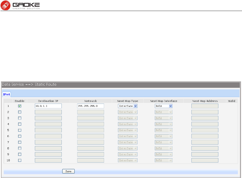
FG7008N User Manual
Page 60 of 111
four IPSEC Proposals can be selected.
3.4.8 Routing
3.4.8.1 Static Route
3.4.8.1.1 IPv4
Choose the menu Data Service→Routing→Static Route→IPv4 to load the following page.
Figure 3-86 Configure IPv4 Static Route
The following items are displayed on this screen:
► Enable: Select it to add and modify the current route. Conversely, disable the current
route.
► Destination IP: Enter the destination host the route leads to.
► Netmask: Enter the Subnet mask of the destination network.
► Next Hop Type: Include Next Hop Interface and Next Hop Address(see following option)
► Next Hop Interface: Specify the interface of next hop for current route
► Next Hop Address: Specify the address of next hop for current route
► Valid: Show the status of current route.
3.4.8.1.2 IPv6
The menu IPV6 is hidden if you don’t enable Ipv6 stack, please refer to configuration index
Network→IPv6 for detail setting.
Choose the menu Data Service→Route→Static Route→IPv6 to load the following page.
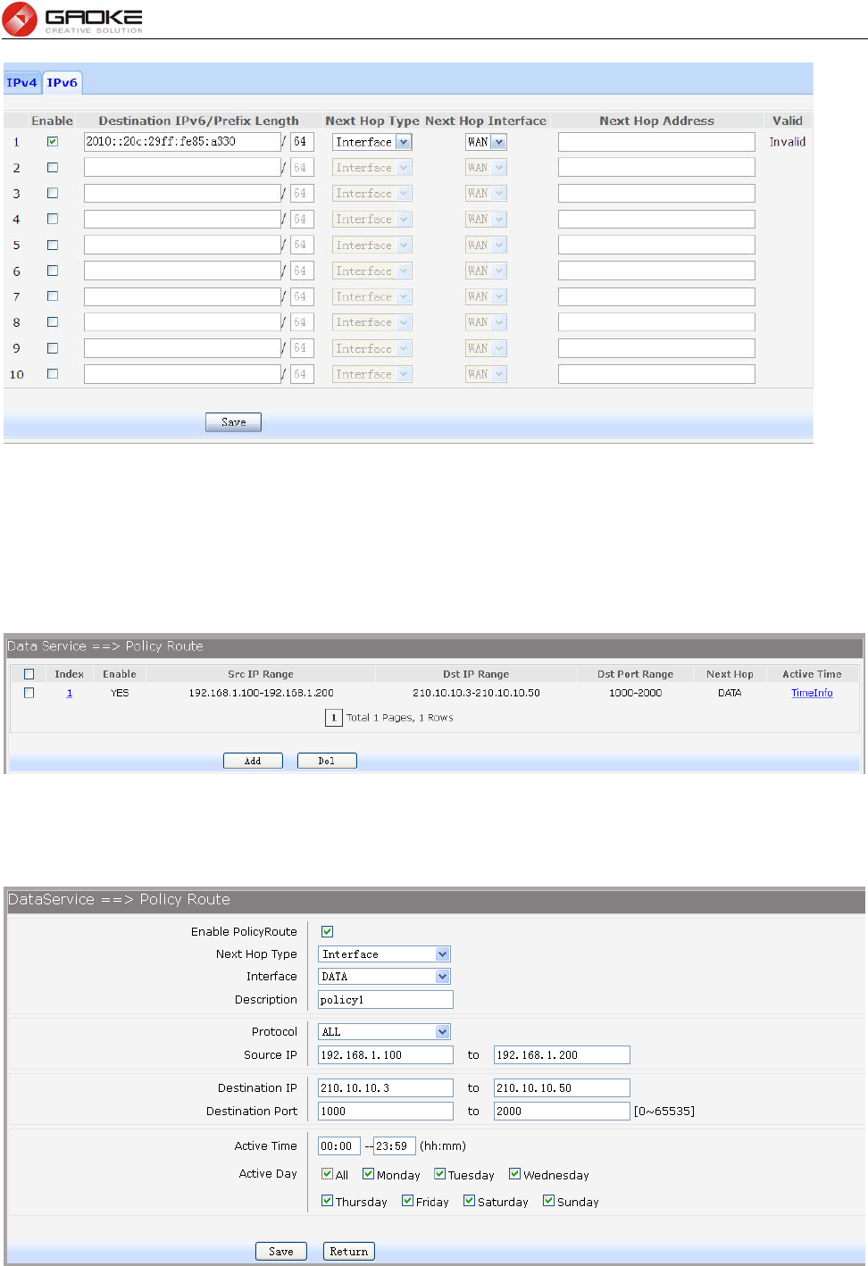
FG7008N User Manual
Page 61 of 111
Figure 3-87 Configure IPv6 Static Route
The configuration options of Ipv6 is similar to Ipv4, the prefix length is equal to mask of Ipv4 address.
3.4.8.2 Policy Route
Choose the menu Data Service→Route→Policy Route to load the following page.
Figure 3-88 View Policy Route
Click the Index in the entry you want to modify. If you want to delete the entry, select it and click the Del.
Click the Add button to add a new entry.
Figure 3-89 Add or Modify Policy Route
The following items are displayed on this page:
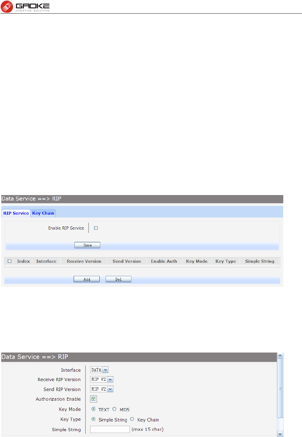
FG7008N User Manual
Page 62 of 111
► Enable PoliceRoute: Enable or disable the entry
► Next Hop Type: Select from pull-down list: Interface, Address.
► Interface: Specify the interface of next hop for the entry.
► Address: Specify the address of next hop for the entry.
► Description: Give description for the entry.
► Protocol: Specify the protocol, TCP, UDP or ALL.
► Source IP: Enter IP address or IP range of source in the rule entry.
► Destination IP: Enter IP address or IP range of destination in the rule entry.
► Destination Port: Specify port or port range of destination in the rule entry.
► Active Time: Specify the active time range for the rule entry.
► Active Day: Specify the active days for the rule entry.
3.4.8.3 RIP
The Routing Information Protocol (RIP) is one of the oldest distance-vector routing protocols, which
employs the hop count as a routing metric.
3.4.8.3.1 RIP Service
Choose the menu Data Service→RIP→RIP Service to load the following page.
Figure 3-90 RIP Service Configuration
The following items are displayed on this page:
► Enable RIP Service: Enable or disable RIP service function globally.
Click the Index in the entry you want to modify. If you want to delete the entry, select it and click the Del.
Click the Add button to add a new entry.
Figure 3-91 Add or Modify RIP Service Entry
The following items are displayed on this page:
► Interface: Specify the interface for the entry.
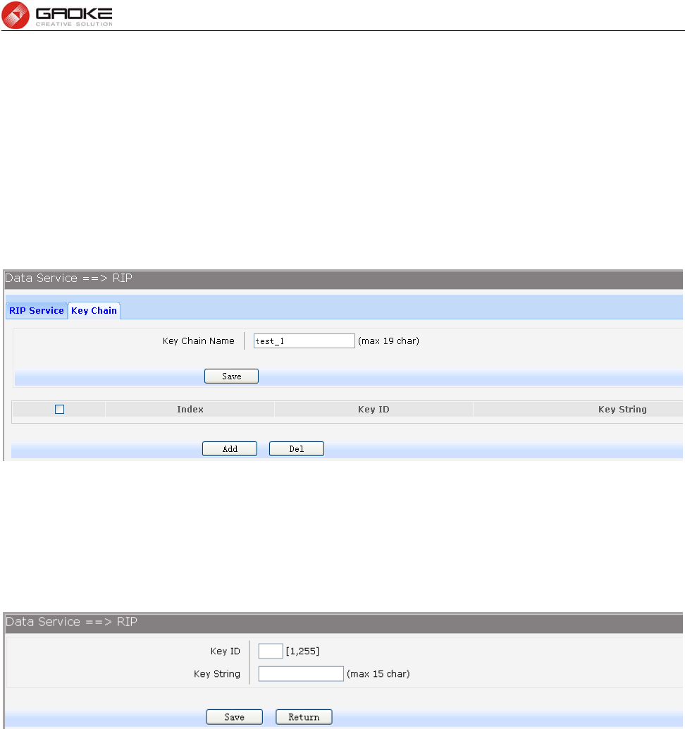
FG7008N User Manual
Page 63 of 111
► Receive RIP Version: Specify receiving RIP version for the entry.
► Send RIP Version: Specify sending RIP version for the entry.
► Authorization Enable: Check the box to enable authorization.
► Key Mode: Specify the encryption mode of key, TEXT(plaintext),MD5(cipertext).
► Key Type: Specify the key from Simple String or Key Chain.
► Simple String: If select Simple String in item of Key Type, enter simple string as key.
3.4.8.3.2 Key Chain
Key Chain is a chain of keys used as RIP authorization key.
Choose the menu Data Service→RIP→Key Chain to load the following page.
Figure 3-92 View RIP Key Chain Configuration
The following items are displayed on this page:
► Key Chain Name: Enter the name of key chain.
Click the Index in the entry you want to modify. If you want to delete the entry, select it and click the Del.
Click the Add button to add a new entry.
Figure 3-93 Add or Modify RIP Key Chain Entry
The following items are displayed on this page:
► Key ID: Enter the ID of the entry.
► Key String: Enter the Key of the entry.
3.4.9 Advanced Parameters
3.4.9.1 UPnP Parameter
The Universal Plug and Play (UPnP) technology is enabling a world in which music and other digital
entertainment content is accessible from various devices in the home without regard for where the media
is stored. Using UPnP devices the whole family can share in the fun together whether it's:
1) Viewing your best family photos via the TV
2) Watching home videos
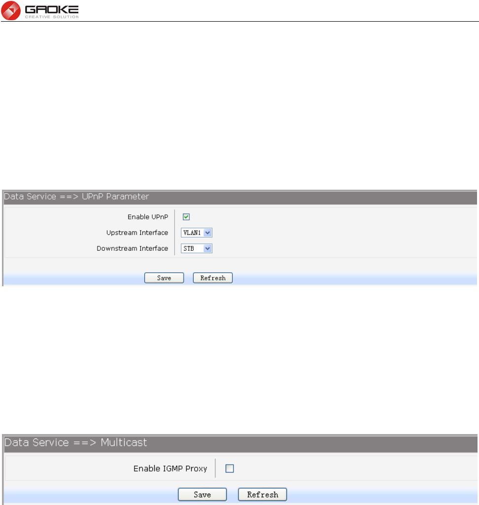
FG7008N User Manual
Page 64 of 111
3) Listening to favorite tunes throughout the house
The Digital Living Network Alliance (DLNA) is a non-profit collaborative trade organization established
by Sony in June 2003, which is responsible for defining interoperability guidelines to enable sharing of
digital media between multimedia devices. DLNA uses UPnP for media management, discovery and
control.
Here, UPNP mainly for DLNA, DLNA server can be automatically discovered by sending NOTIFY via
Multicast, and DLNA clients can search DLNA servers by sending M-SEARCH via Multicast.
Choose the menu Data Service→Advanced Parameters→UPnp Parameter to load the following
page.
Figure 3-94 Configure UPnp
The following items are displayed on this screen:
► Enable UPnP: Enable or disable the UPnP function globally.
► Upstream Interface: The network interface connected to the DLNA server.
► Downstream Interface: The network interface connected to the DLNA client.
3.4.10 Multicast
Choose the menu Data Service→Multicast to load the following page.
Figure 3-95 Configure Multicast
The following items are displayed on this screen:
► Enable IGMP Proxy: Enable or disable the IGMP proxy function globally. Currently, IGMP proxy is
mainly used for IPTV.
3.4.11 USB Storage
USB Storage function let Windows OS share files of USB storage mounted on embedded device by
Samba and ftp.
1) User Management
Manage the list of users which access USB storage.
Choose menu Data Service→USB Storage to load the following page.
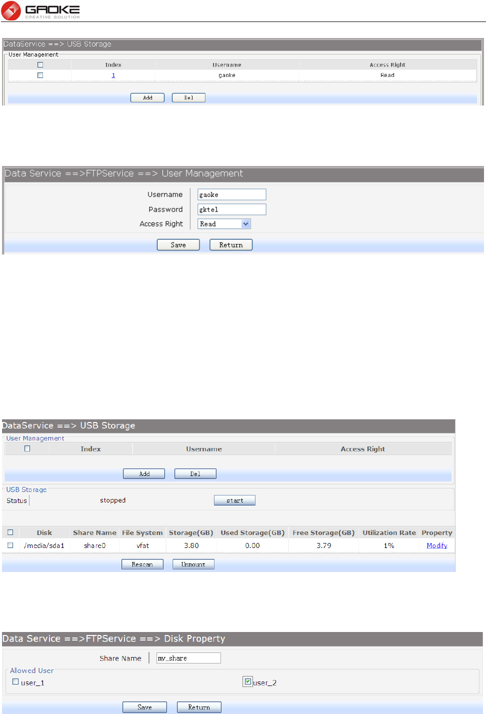
FG7008N User Manual
Page 65 of 111
Figure 3-96 View User Management Configuration
Click the Index in the entry you want to modify. If you want to delete the entry, select it and click the Del.
Click the Add button to add a new entry.
Figure 3-97 Add or Modify User Management Entry
The following items are displayed on this screen:
► Username: Enter user name of this entry.
► Password: Enter password of this entry.
► Access Right: Select access right from pull-down list, Read or Read/Write.
2) USB Storage
Scan the partitions of USB Storage by click Rescan button and umount specified partition by clicking
Umount button. Click start to start service, click stop to stop service.
Figure 3-98 View USB Storage
Click Modify to load the following page:
Figure 3-99 Modify USB Storage
The following items are displayed on this screen:
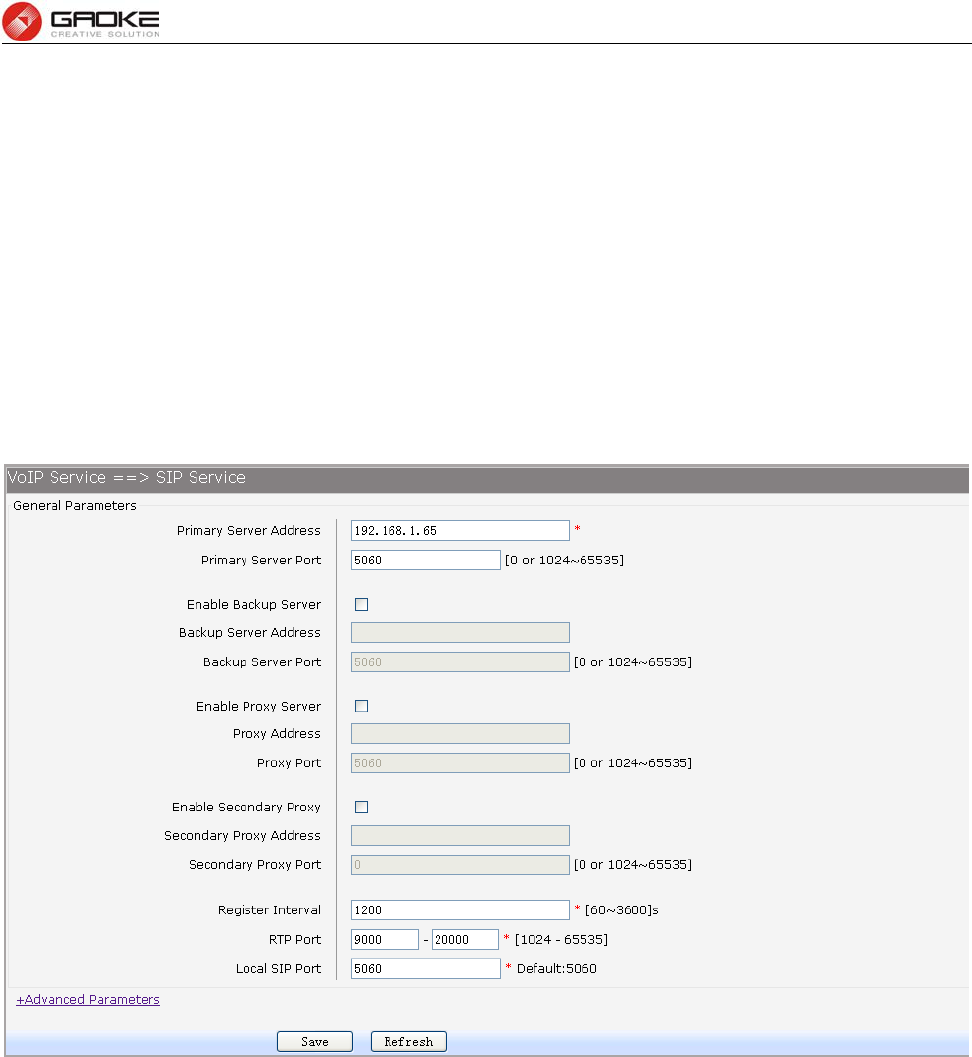
FG7008N User Manual
Page 66 of 111
► Share Name: Enter the share name.
► Allowed User: Select the users need to access the partition of the entry.
3.5 VOIP Service
The Session Initiation Protocol (SIP) is a signaling protocol used for establishing sessions in an IP
network. The protocol can be used for creating, modifying and terminating two-party (unicast) or
multiparty (multicast) sessions. Sessions may consist of one or several media streams.
3.5.1 SIP Service
Choose the menu VOIP Service→SIP Service to load the following page.
Figure 3-100 Configure General Parameters of SIP Service
The following items are displayed on this screen:
► Primary Server Address: Domain or IP of SIP server.
► Primary Server Port: Listening port of SIP server.
► Enable Backup Server: Enable or disable backup SIP server.
► Backup Server Address: Domain or IP of backup SIP server.
► Backup Server Port: Listening port of backup SIP server.
► Enable Proxy Server: Enable or disable Proxy server.
► Proxy Address: Domain or IP of proxy server.
► Proxy Port: Listening port of proxy server.
► Enable Secondary Proxy: Enable or disable backup proxy server.
► Secondary Proxy Address: Domain or IP of backup proxy server.
► Secondary Proxy Port: Listening port of backup proxy server.
► Register Interval: Enter the desired time interval at which the sip UA will send register
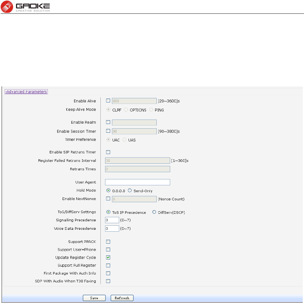
FG7008N User Manual
Page 67 of 111
message.
► RTP Port: Local RTP port range.
► Local SIP Port: Local listening port.
Click +Advanced Parameters to load the following page.
Figure 3-101 Configure Advanced Parameters of SIP Service
The following items are displayed on this screen:
► Enable Alive: After successful registration, whether to send keep-alive packets.
► Keep Alive Mode: Keep alive mode: CLRF, OPTIONS or PING.
► Enable Realm: Check the box to enable SIP signaling packets with realm field information.
► Enable Session Timer: Enable or disable UAC / UAS session refresh mode.
► Enable SIP Retrans Timer: When registration fails, whether to initiate retransmission, retransmission
cycle and time with configuration.
► User Agent: Check the box to enable signaling packets with User Agent field.
► Hold Mode: Select the SIP signal format of call hold.
► Enable Next Nonce: Enable SIP packets with nonce count field information, incremented each
one and with a maximum value.
► Support PRACK: Enable or disable provisional response. If enabled, 1xx (except 100rel)
messages are required to respond with ACK.
► Support User=Phone: Whether SIP signaling packets with User = Phone field information.
► Update Register Cycle: Based on server response to update registration period.
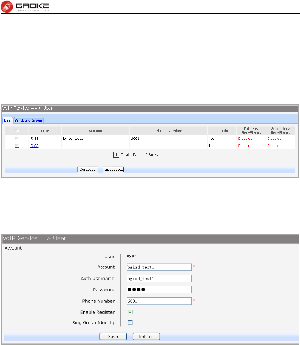
FG7008N User Manual
Page 68 of 111
► Support Full Register: Each registration packets are generated, rather than re-issued.
► First Package With Auth Info: The first registration packet with authentication information.
► SDP With Audio When T38 Faxing: T38 fax signaling packet with audio information.
3.5.2 User
3.5.2.1 User
Choose the menu VOIP Service→User→User to load the following page.
Figure 3-102 User Configuration
Click the Register button to start the registering to the SIP server.
Click the Unregister button to start the un-registering to the SIP server.
Click the User in the entry you want to modify to load the following page.
Figure 3-103 Configure User
The following items are displayed on this screen:
► Account: Account name registered to SIP server.
► Auth Username: Username of the account.
► Password: Password of the account.
► Phone number: Caller and called number of subscriber line.
► Enable Register: Enable registering.
► Ring Group Identity: Phone number configured as one hunt group, after saving, the configuration
can be seen in the Centrex page.
3.5.2.2 Wildcard Group
Choose the menu VOIP Service→User→Wildcard Group to load the following page.
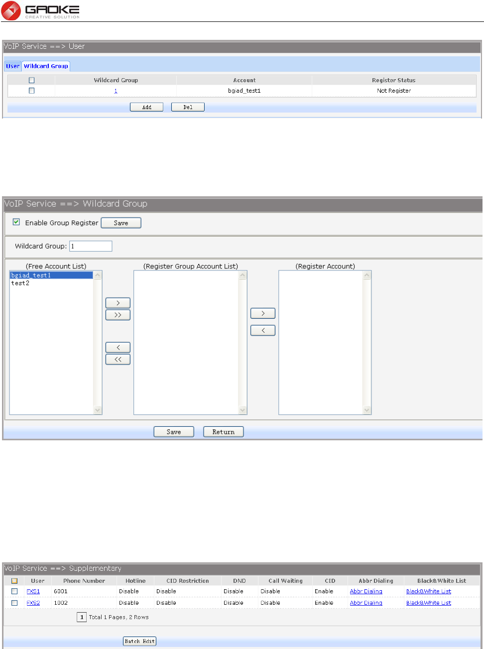
FG7008N User Manual
Page 69 of 111
Figure 3-104 Wildcard Group Configuration
Click the Wildcard Group in the entry you want to modify. If you want to delete the entry, select it and
click the Del. Click the Add button to add a new entry.
Figure 3-105 Add or Modify Wildcard Group Configuration
The following items are displayed on this screen:
► Enable Group Register: Enable or disable the group register function globally.
3.5.3 Supplementary
Choose the menu VOIP Service→Supplementary to load the following page.
Figure 3-106 User Supplementary
Click the User in the entry you want to modify to load the following page. You can also select
multiple, then click Batch Edit to batch configuration.
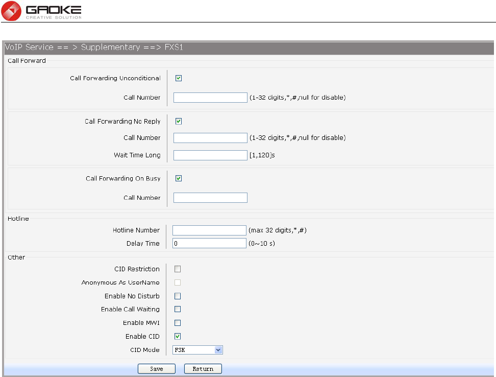
FG7008N User Manual
Page 70 of 111
Figure 3-107 Modify Supplementary Configuration
The following items are displayed on this screen:
► Call Forwarding Unconditional: Enable or disable CFU function, if enabled, enter Call Number.
1) Set by keypad service system: *57*TN#, TN is the phone
number to be redirected to.
2) Cancel by keypad service system: #57#.
► Call Forwarding No Reply: Enable or disable CFNR, if enabled, enter Call Number and Wait
Time Long.
1) Set by keypad service system: *41*TN#, TN is the phone
number to be redirected to.
2) Cancel by keypad service system: #41#.
► Call Forwarding On Busy: Enable or disable CFB function, if enabled, enter Call Number.
1) Set by keypad service system: *40*TN#, TN is the phone
number to be redirected to.
2) Cancel by keypad service system: #40#.
► Hotline Number: Enter number to hotline function, empty expressed disable.
1) Set delay hotline number by Keypad service system: *52*TN#,
TN is the hotline number.
2) Cancel delay hotline number by Keypad service system: #52#.
3) Set instant hotline number by Keypad service system:
*42*TN#, TN is the hotline number.
4) Cancel instant hotline number by Keypad service system:
#42*EN#, instant hotline can only be deactivated with other
extension; EN is the extension number which needs to deactivate
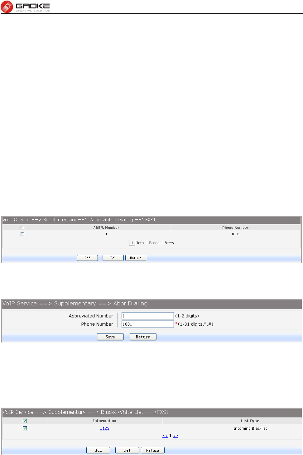
FG7008N User Manual
Page 71 of 111
instant hotline.
► Delay Time: Time 0 indicates immediate Hotline, Otherwise, indicates delay
Hotline. The Delay Time must be configured on the WEB.
► CID Restriction: Enable or disable CID Restriction. If Anonymous As UserName is
chosen, user name content is Anonymous also.
► Enable No Disturb: Allows block incoming calls at any time.
► Enable Call Waiting: When you talking, a third party phone comes in, you can hear the
beep tone.
► Enable MWI: Enable or disable MWI (Message-waiting indicator) function.
► Enable CID: Enable or disable to send CID to phone.
► CID Mode: There are two methods used for sending caller ID information
depending on the application and country specific requirements:
FSK: caller ID generation using Frequency Shift Keying (FSK)
DTMF: caller ID generation using DTMF signaling.
4) Abbreviated Dialing allows you to store selected phone numbers for quick and easy dialing. Each
telephone number can be dialed by using a one to two-digit code with a simple prefix. Stored
numbers may be up to 32 digits in length.
If you want to add or remove abbreviated dialing numbers, click the Abbr Dialing to load the
following page.
Figure 3-108 View Abbreviated Dialing Configuration
Click the Del button to delete the entries you select.
Click the Add button to add a new entry.
Figure 3-109 Add Abbreviated Dialing Entry
The following items are displayed on this screen:
► Abbreviated Number: Enter the abbreviated number.
► Phone Number: Enter the Actual phone number.
5) If you want to add or remove black&white list, click the Black&White List to load the following page.
Figure 3-110 Black&White List Configuration
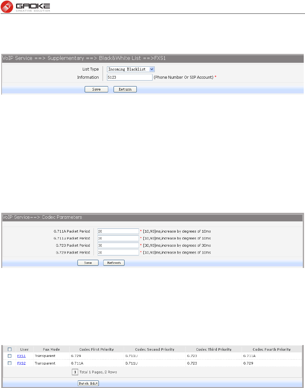
FG7008N User Manual
Page 72 of 111
Click the Information in the entry you want to modify. If you want to delete the entry, select it and click
the Del.
Click the Add button to add a new entry.
Figure 3-111 Add or Modify Black&White List Entry
The following items are displayed on this screen:
► List Type: Choose type of Black&White List, four types are provided:
Incoming Blacklist, Incoming Whitelist, Outgoing Blacklist, Outgoing Whitelist.
► Information: Enter the phone number or sip account.
3.5.4 Codec Parameters
1. Packet Period defines how long the device sends a RTP packet to the other side. The smaller the value,
the more bandwidth usage. The larger the value, the more voice delay. Choose the menu VOIP
Service→Codec Parameters to load the following page.
Figure 3-112 Configure Packet Period
► G.711A Packet Period: RTP packetization period of G.711A codec.
► G.711u Packet Period: RTP packetization period of G.711U codec.
► G.723 Packet Period: RTP packetization period of G.723 codec.
► G.729 Packet Period: RTP packetization period of G.729 codec.
2. Choose the menu VOIP Service→Codec Parameters to load the following page.
Figure 3-113 View Fax Mode&Codec Priority Configuration
To modify fax mode or codec priority of users, click the User in the entry you want to modify to load the
following page. You can also select multiple, then click Batch Edit to batch configuration.
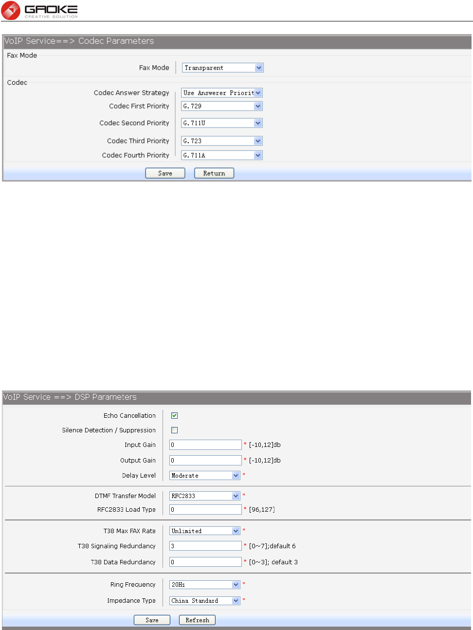
FG7008N User Manual
Page 73 of 111
Figure 3-114 Add or Modify Fax Mode&Codec Priority
The following items are displayed on this screen:
► Fax Mode: Choose fax mode, three types are provided: Transparent, T38, VBD.
► Codec Answer Strategy: Two modes are provided:
Use Answerer Priority: Codec selection decisions based on the priority
level configuration
Use Offerer Priority: Codec selection decision based on caller’s
priority.
► Codec Priority: If Use Answerer Priority is selected, set the priority of codec.
3.5.5 DSP Parameters
Choose the menu VOIP Service→DSP Parameters to load the following page.
Figure 3-115 Configure DSP Parameters
The following items are displayed on this screen:
► Echo Cancellation: Enable or disable echo cancellation.
► Silence Detection/Suppression: Enable or disable silence detection and silence suppression.
► Input Gain: Configure the input gain value.
► Output Gain: Configure the input gain value

FG7008N User Manual
Page 74 of 111
► Delay Level: Choose the delay level, five levels are provided: Minimum,
Smaller, Moderate, Larger, Maximum.
► DTMF Transfer Model: Select DTMF transmission mode: In-Band, INFO, RFC2833.
► RFC2833 Load Type: If RFC2833 is selected, specify payload type of RFC2833.
► T38 Max FAX Rate: Select the maximum rate, when using T38 fax mode: Unlimited,
2400bps, 4800bps, 7200bps, 9600bps, 12000bps, 14400bps.
► T38 Signaling Redundancy: Configure the redundancy of T38 signal.
► T38 Data Redundancy: Configure the redundancy of T38 data.
► Ring Frequency: Choose the ring frequency: 20Hz, 25Hz.
► Impedance Type: Choose the impedance type: 600Ώ, China Standard, Switzerland
Standard.
3.5.6 Digitmap
The destination number will be sent all in one time for SIP application, digitmap is used to determine
exactly when there are enough digits entered from the user to place a call. If the number length of suited
route item is fixed, the number will be sent when specified number of digits is received; the call will be
disconnected when inter-digit timeout expires. If the number length of suited route item is indefinite,
there are 3 ways to determine whether the digits is enough, press pound(#) key, timeout expires or
digitmap comparing. If digits dialed partly matching with digitmap patterns, continue waiting of number
receiving. If they match, send the number immediately. If not, send the number immediately too, in order
to play the prompts.
Table 3-1 Digitmap Characters
Character Description
0~9 Indicates specific digits in a telephone number expression.
X Wildcard, matches any digit, excluding “#” and “*”.
* Digit star
# Digit pound
- Connects the start and the end of a range
[] Indicates the a range of numbers(not letters).
. Matches an arbitrary number of occurrences of the
preceding digit, including 0.
| Indicates a choice of matching expressions (OR).
T Inter-digit timeout expires
S Short timer expires, usually place at the middle of an
expression
Digitmap Example: 8XXXXXXX|1[0-24]0|2[18].3|3XXSXX|[0-9*#][0-9*#][0-9*#].#|[0-9*#].T
“8XXXXXXX” denotes numbers start with 8, the length is 8.
“1[0-24]0” denotes numbers include 100, 110, 120 and 140.
“2[18].3” denotes numbers that start with 2 and end with 3, there can be arbitrary length of 1 or 8
after the first digit 2. 23, 213, 2183 is matched.
“3XXSXX” denotes numbers start with 3, the length can be 3 or 5. If the short timer configured
expires between the third digit and the fourth digit, the number will be sent.
“[0-9*#][0-9*#][0-9*#].#” denotes numbers end with #, and the length is no less than 2.
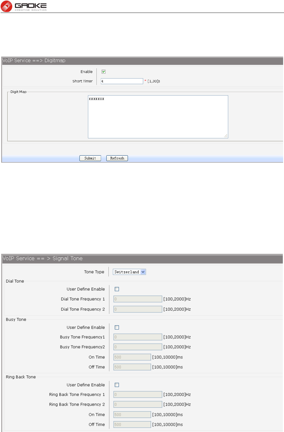
FG7008N User Manual
Page 75 of 111
“[0-9*#].T” denotes any number that dialing time out.
Choose the menu VOIP Service→Digitmap to load the following page.
Figure 3-116 Configure Digitmap
The following items are displayed on this screen:
► Enable: Enable or disable digit map function.
► Short Timer: Enter the time of Short Timer in second.
► Digit Map: Enter the digit map rules.
3.5.7 Signal Tone
Choose the menu VOIP Service→Signal Tone to load the following page.
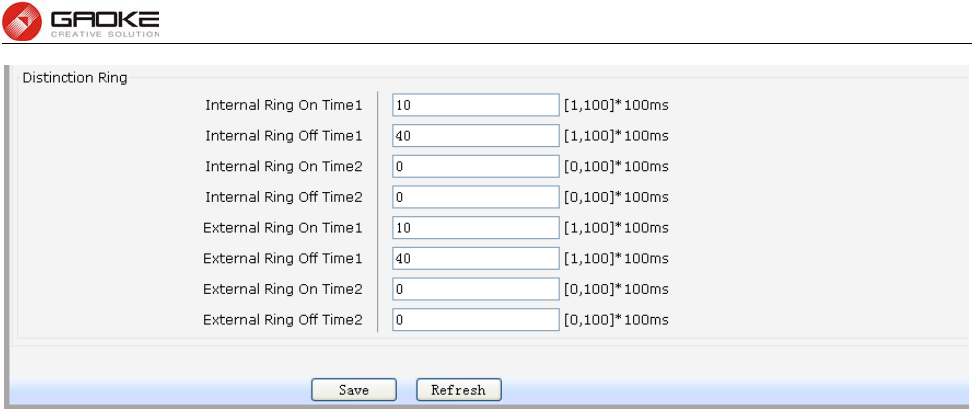
FG7008N User Manual
Page 76 of 111
Figure 3-117 Configure Signal Tone
The following items are displayed on this screen:
► Tone Type: Select the type of signal tone.
Dial Tone
► User Define Enable: Whether to use user-defined dial tone frequency.
► Dial Tone Frequency 1:
► Dial Tone Frequency 2:
Busy Tone
► User Define Enable: Whether to use user-defined busy tone frequency.
► Busy Tone Frequency 1:
► Busy Tone Frequency 2:
► On Time:
► Off Time:
Ring Back Tone
► User Define Enable: Whether to use user-defined ringback tone frequency.
► Ring Back Tone Frequency 1:
► Ring Back Tone Frequency 2:
► On Time:
► Off Time:
Distinction Ring: Specify the ring cadence for the FXS port. In these fields, you specify the on and off
pulses for the ring. The ring cadence that should be configured differs between internal call and external
call.
3.5.8 FXS Parameters
Choose the menu VOIP Service→FXS Parameters to load the following page.
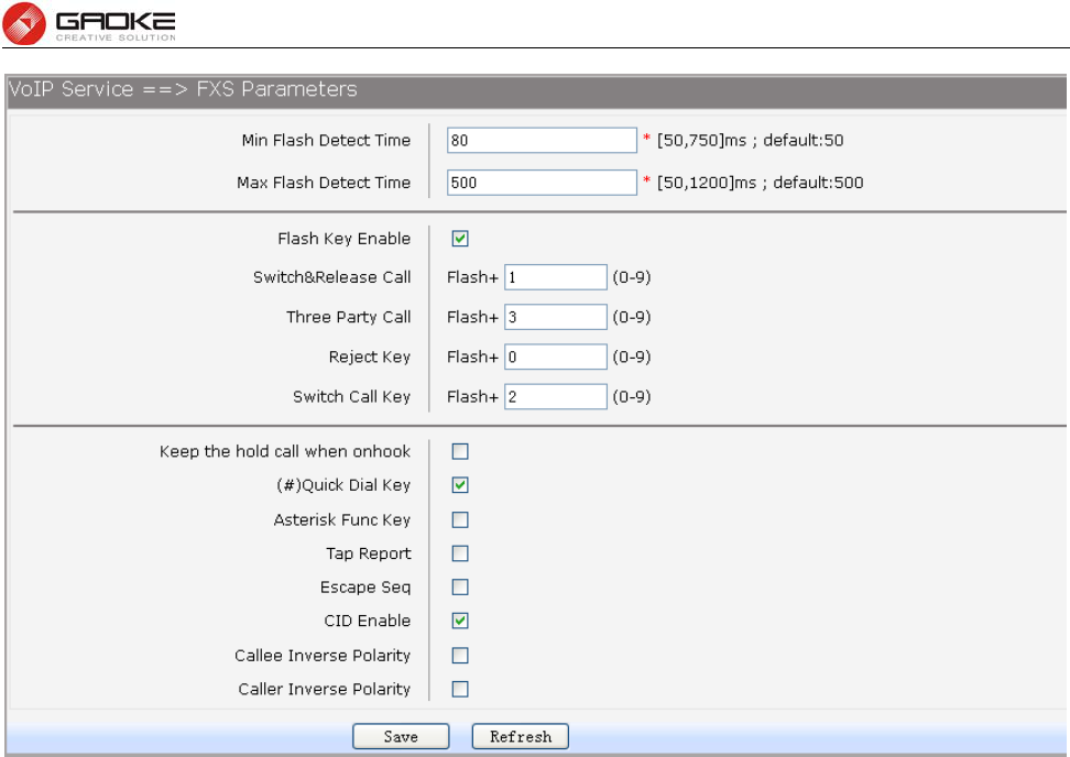
FG7008N User Manual
Page 77 of 111
Figure 3-118 Configure FXS Parameters
The following items are displayed on this screen:
► Min Flash Detect Time: The minimum time to detect the flash.
► Max Flash Detect Time: The maximum time to detect the flash.
► Flash Key Enable: Whether to enable digit detect after flash.
► Switch&Release Call: If the digit specified is detected after flash, terminate the active call and
recover the call on hold.
► Three Party Call: If the digit specified is detected after flash, enter the conference mode.
► Reject Key: If the digit specified is detected after flash, reject the call on hold.
► Switch Call Key: If the digit specified is detected after flash, hold the active call and recover
the call on hold.
► Keep the hold call when onhook: If selected, when hanging up in this context, the telephone rings
to notify the user there is still a call on hold.
► (#)Quick Dial Key: Whether to send telephone number immediately after receiving the # key.
► Asterisk Func Key: Whether to use the ‘*’ key as flash key.
► Tap Report: Whether to report an event to server when flash detected.
► Escape Seq: Whether to use an escape characters when sending special DTMF.
► CID Enable: Whether to enable caller id globally.
► Callee Inverse Polarity: Whether to activate the Polarity Reversal for FXS callee.
► Caller Inverse Polarity: Whether to activate the Polarity Reversal for FXS caller.
3.5.9 Centrex
To control call each other of internal number in the same device, choose the menu
VOIP Service→Centrex to load the following page.
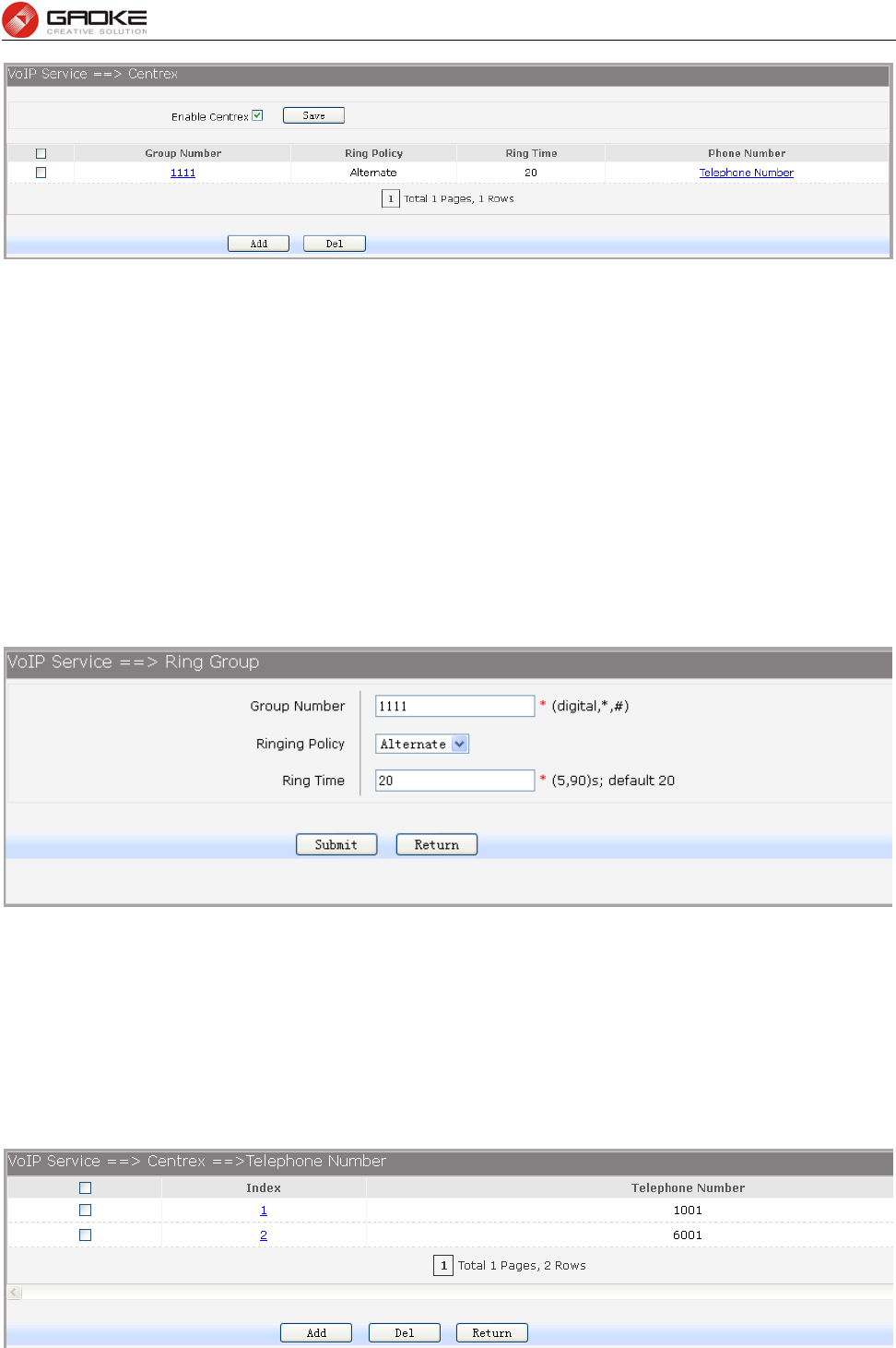
FG7008N User Manual
Page 78 of 111
Figure 3-119 Centrex&Ring Group Configuration
The following items are displayed on this screen:
► Enable Centrex: Whether to enable centrex function globally.
A hunt group is a collection of extensions that ring in a particular order when the hunt group number is
dialed. Hunt groups usually have a phone number associated with them, which are referred to as the
group number. Ordinal hunt groups always start ringing the first extension in the list. Alternate hunt
groups remember the last number that ringed first and begins ringing on the next number in the list.
when the end of the list is reached, both wrap around to the first number in the list again. With a parallel
hunt group, all extensions in the list will ring at the same time.
To delete an exist entry, select it and click the Del.
To modify ring policy or ring time configuration, please click the Group Number in the exist entry which
you want to modify. You can also click the Add button to add a new entry.
Figure 3-120 Add or Modify RingGroup
The following items are displayed on this screen:
► Group Number: The phone number of this ring group.
► Ringing Policy: Phone ringing policy: Alternate, Ordinal, Parallel.
► Ring Time: Ring time of each member.
Click Submit button when finished, then you can Add telephone numbers to this Ring Group, you can
also click the Phone Number in the exist entry to Add or Del telephone numbers.
Figure 3-121 Add or Delete Number of RingGroup
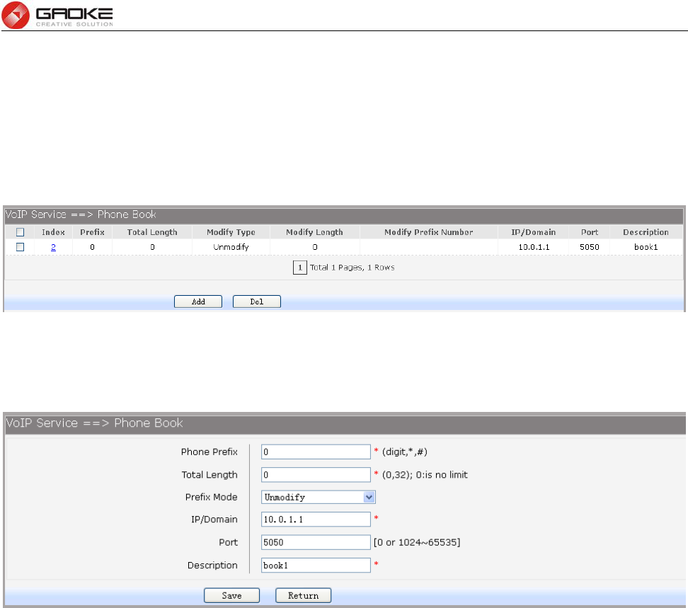
FG7008N User Manual
Page 79 of 111
The following items are displayed on this screen:
► Telephone Number: The number will be added to the ring group.
3.5.10 Phone Book
Choose the menu VOIP Service→Phone Book to load the following page.
Figure 3-122 Configure Phone Book
Click the Index in the entry you want to modify. If you want to delete the entry, select it and click the Del.
Click the Add button to add a new entry.
The following items are displayed on this screen:
► Phone Prefix: The prefix of this phone book.
► Total Length: The total length of number to wait before sending.
► Prefix Mode: Mode of processing number prefix: Unmodify, Remove, Add, Modify.
► IP/Domain: The IP address or domain of destination.
► Port: The port of destination.
► Description: Description of this rule.
3.6 System
3.6.1 Time Management
Menu of time management is used to manage system time.
1) Manual Configuration
Choose the menu Data Service→Time Management and select Manual Configuration to load the
following page.
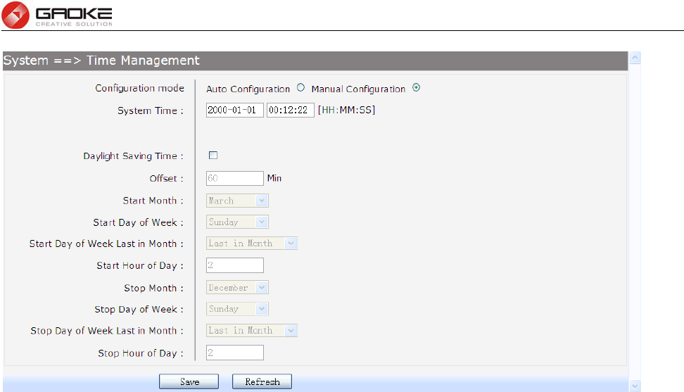
FG7008N User Manual
Page 80 of 111
Figure 3-123 Time Manual Configuration
The following items are displayed on this screen:
► Configuration mode: Specify configuration mode of time, Auto Configuration or Manual
Configuration, default is Manual Configuration.
► System Time: Enter the system time under Manual Configuration.
► Daylight Saving Time: Enable or disable the Daylight Saving Time(DST).
► Offset: Enter the offset of DST.
► Start Month: Specify the start month of DST, range from 1 to 12 in one year.
► Start Day of Week: Specify the start weekday of DST, range from Sunday to Saturday.
► Start Day of Week Last in Month: Specify the order of start weekday in the month from pull-down list
as following:
First in Month
Second in Month
Third in Month
Fourth in Month
Last in Month
► Start Hour of Day: Specify the start hour of DST, range from 0 to 23 in one day.
► End Month: Specify the end month of DST, range from 1 to 12 in one year.
► End Day of Week: Specify the end weekday of DST, range from Sunday to Saturday.
► End Day of Week Last in Month: Specify the order of end weekday in the month, similar as Start
Day of Week Last in Month.
► End Hour of Day: Specify the end hour of DST, range from 0 to 23 in one day.
2) Auto Configuration
Choose Auto Configuration to load the following page:
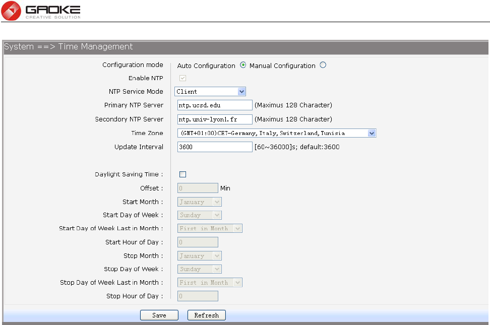
FG7008N User Manual
Page 81 of 111
Figure 3-124 Time Auto Configuration
The following items are displayed on this screen:
► Enable NTP: Enable or disable NTP service.
► NTP Service Mode: Specify CPE role as NTP Client or both Client and Server.
► Primary NTP Server: Specify the primary NTP server for role as NTP client.
► Second NTP Server: Specify the second NTP server for role as NTP client.
► Time Zone: Enter the local time zone.
► Update Interval: Specify update interval for role as NTP client.
3.6.2 Upgrade
3.6.2.1 Application
Firmware upgrade via WEB interface is available. There are 2 steps to complete firmware updating.
1) Choose menu “SystemUpgrade”, then select the right firmware file, click Upgrade, wait a
few minutes for firmware downloading and programming.
2) Choose menu “System Reboot”, then click Reboot button to reset the device.
3.6.2.2 Configuration
3.6.2.2.1 Update Configuration
Configuration updating via WEB interface is available. There are 2 steps to complete configuration
updating.
1) Choose menu “SystemUpgrade”, then select the right configuration file, click Upgrade, wait
a few seconds for downloading and programming.
2) Choose menu“System Reboot”, then click Reboot button to reset the device.
3.6.2.2.2 Export Configuration
Configuration exporting via WEB interface is available. Click the "Export Configuration File" to export
the configuration file.
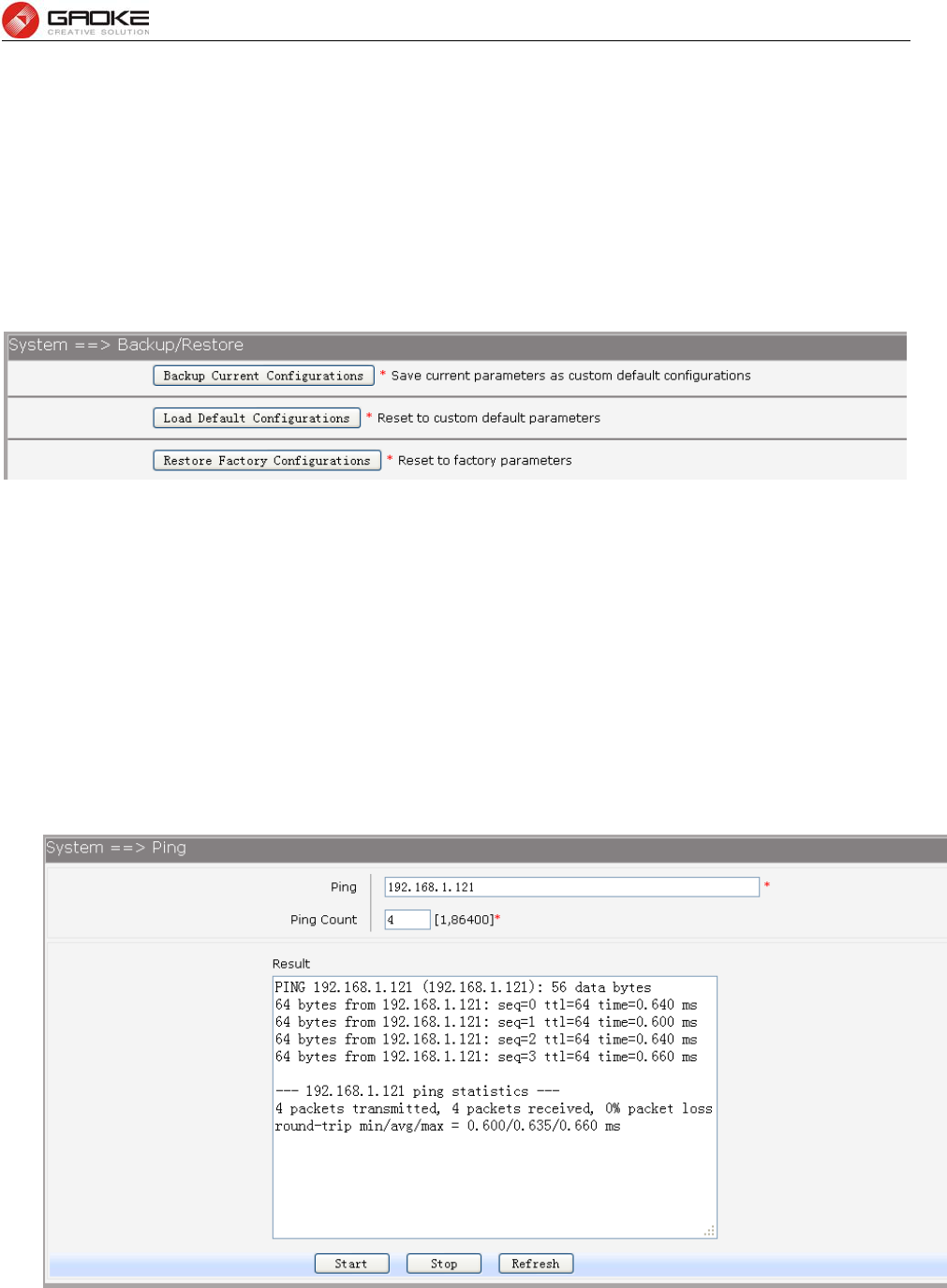
FG7008N User Manual
Page 82 of 111
Web interface configuration index: SystemUpgrade( Configuration).
3.6.3 Reboot System
Choose menu“System Reboot”, then click Reboot button to reset the device.
3.6.4 Backup/Restore
Choose the menu System→Backup/Restore to load the following page.
Figure 3-125 Backup/Restore Configurations
The following items are displayed on this screen:
► Backup Current Configurations: Save current parameters as customer default parameters.
► Load Default Configurations: To reset to customer default parameters.
► Restore Factory Configurations: To reset to factory parameters.
3.6.5 Diagnostic
3.6.5.1 Ping
Choose menu “SystemDiagnosticPing”, and then you can use Ping function to check connectivity
of your network in the following screen.
Figure 3-126 Ping Diagnostic
The following items are displayed on this screen:
► Ping: Enter the IP Address or Domain Name of the PC whose connection you wish to
diagnose.
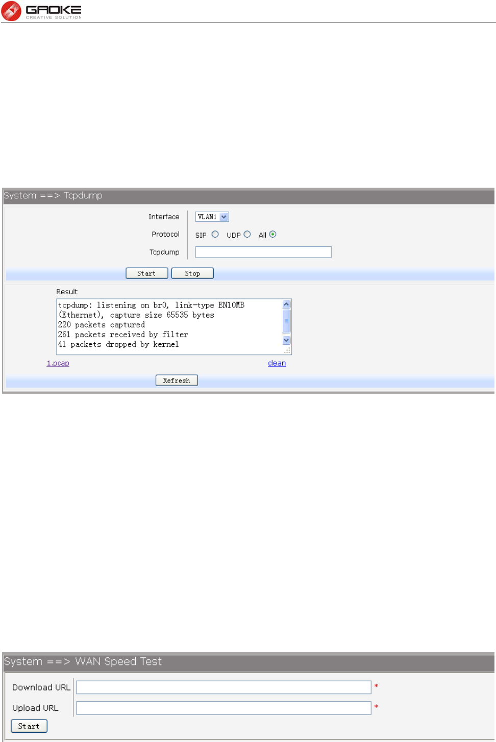
FG7008N User Manual
Page 83 of 111
► Ping Count: Specifies the number of Echo Request messages sent.
► Result: This page displays the result of diagnosis.
Click Start button to check the connectivity of the Internet.
Click Stop button to stop sending the Echo Request messages.
Click Refresh button to refresh the web page.
3.6.5.2 Tcpdump
You can use tcpdump tool to capture the packets, and show the result of capture packets.
Choose the menu System→Diagnostic→Tcpdump to load the following page.
Figure 3-127 Tcpdump Diagnostic
The following items are displayed on this screen:
► Interface: By selecting the interface, only packets through this interface will be captured.
► Protocol: By selecting the protocol, only packets of this protocol will be captured.
► Tcpdump: Enter some options of tcpdump(e.g. -n -s0 -c 100)
► Result: This page displays the result of capture packets.
Click Start button to capture the packets which correspond to the configuration requirement.
Click Stop button to stop capturing the packets.
Click "*.pcap" to open or download the capture packets file.
Click "clean" to delete all the packets file.
Click Refresh button to refresh the web page.
3.6.5.3 WAN Speed Test
Test the download speed and upload speed of WAN interface, and show the result on the web page.
Choose the menu System→Diagnostic→WAN Speed Test to load the following page.
Figure 3-128 WAN Speed Test
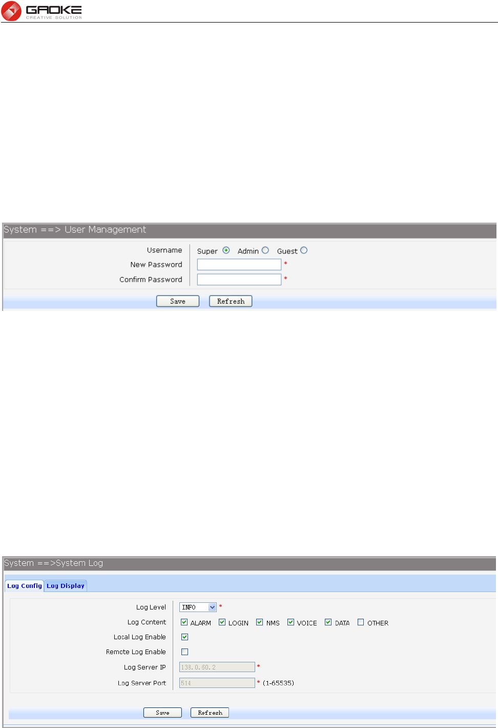
FG7008N User Manual
Page 84 of 111
The following items are displayed on this screen:
► Download URL: Enter the URL to test the download speed of WAN. For example
http://speedtest1.szunicom.com/speedtest/random1000x1000.jpg
► Upload URL: Enter the URL to test the upload speed of WAN. For example
http://speedtest1.szunicom.com/speedtest/random2000x2000.jpg
Click the Start button to starting test.
3.6.6 User Management
You can change the factory default user password of the device.
Choose the menu System→User Management to load the following page.
Figure 3-129 User Management
The following items are displayed on this screen:
► Username: You can select the user with different permissions. However, you can not select
the user whose permission is higher than your permission.
► New Password: Enter the new password for specified user, not more than 32 characters, and
the space is not supported.
► Confirm Password: Enter the new password again to confirm for specified user, not more than 32
characters, and the space is not supported.
Click the Save button when finished.
3.6.7 System Log
3.6.7.1 Log Config
Choose the menu System→System Log→Log Config to load the following page.
Figure 3-130 Configure System Log
The following items are displayed on this screen:
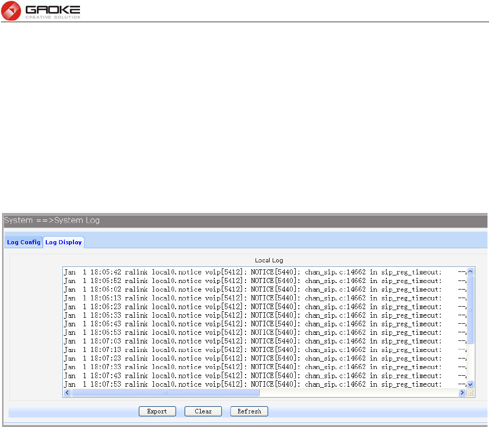
FG7008N User Manual
Page 85 of 111
► Log Level: By selecting the log level, only logs of this level will be shown.
► Log Content: By selecting the log content, only logs of selected content will be shown.
► Local Log Enable: Check this box to enable local log function.
► Remote Log Enable: Check this box to enable remote log function, the logs will be send to the Log
Server.
► Log Server IP: Enter the IP address of the Log Server.
► Log Server Port: Enter the port that Log service used.
Click the Save button when finished.
3.6.7.2 Log Display
Choose the menu System→System Log→Log Display to load the following page.
Figure 3-131 Display System Log
Click the Export button to export all the local logs as a file.
Click the Clear button to clear all the local logs from the device permanently, not just from the page.
Click Refresh button to refresh the web page.
3.6.8 TR069
TR-069 (Technical Report 069) is a Broadband Forum technical specification entitled CPE WAN
Management Protocol (CWMP). It defines an application layer protocol for remote management of
end-user devices. As a bi-directional SOAP/HTTP-based protocol, it provides the communication
between customer-premises equipment (CPE) and Auto Configuration Servers (ACS). It includes both a
safe auto configuration and the control of other CPE management functions within an integrated
framework.
Choose the menu System→TR069 to load the following page.
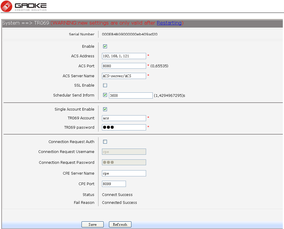
FG7008N User Manual
Page 86 of 111
Figure 3-132 Configure TR069
The following items are displayed on this screen:
► Serial Number: The serial number of device. Read only.
► Enable: Enable or disable the TR069 function globally.
► ACS Address: Enter the IP address or domain name of ACS.
► ACS Port: Enter the port of ACS.
► ACS Server Name: Enter the TR069 server name of ACS.
► SSL Enable: Enable or disable the SSL(Secure Sockets Layer) for TR069.
► Schedular Send Inform: Whether or not the CPE must periodically send CPE information to
Server using the Inform method call. Enter the duration in seconds
of the interval if enabled.
► Single Account Enable: Whether or not the TR069 Account is enabled.
► TR069 Account: Username used to authenticate the CPE when making a
connection to the ACS.
► TR069 password: Password used to authenticate the CPE when making a
connection to the ACS.
► Connection Request Auth: Whether to authenticate an ACS making a Connection Request to
the CPE.
► Connection Request Username: Username used to authenticate an ACS making a Connection
Request to the CPE.
► Connection Request Password: Password used to authenticate an ACS making a Connection
Request to the CPE.
► CPE Server Name: A part of the HTTP URL for an ACS to make a Connection
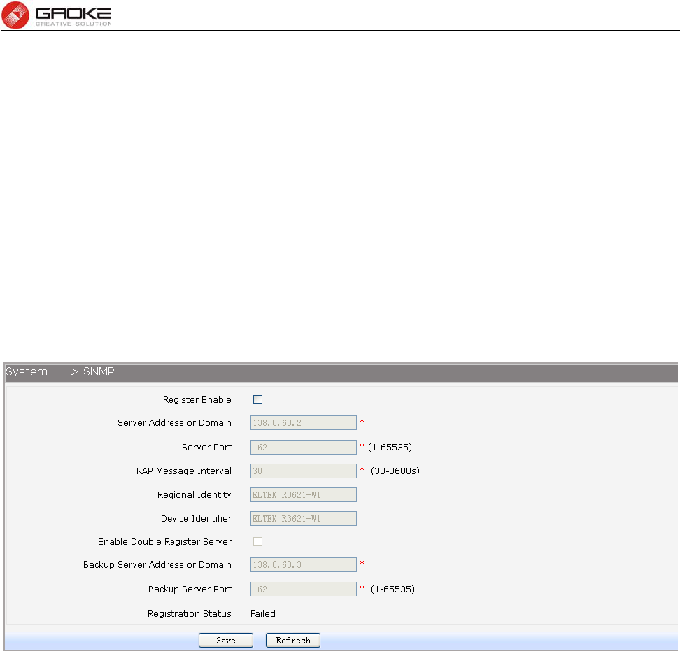
FG7008N User Manual
Page 87 of 111
Request notification to the CPE. In the form:http://host:port/path
► CPE Port: A part of the HTTP URL for an ACS to make a Connection Request
notification to the CPE. In the form:http://host:port/path
► Status: Connection Status when CPE making a connection to the ACS.
Read only.
► Fail Reason: Show reason for the failure when CPE making a connection to the
ACS. Read only.
Click the Save button when finished.
Click Refresh button to refresh the web page.
3.6.9 SNMP
You can configure the SNMP parameters and view the registration status of SNMP. Choose the
menu System→SNMP to load the following page.
Figure 3-133 Configure SNMP
The following items are displayed on this screen:
► Register Enable: Check this box to enable SNMP register.
► Server Address or Domain: Enter the IP address or domain name of register server.
► Server Port: Enter the port of Register Server.
► TRAP Message Interval: Set the sending interval between TRAP messages.
► Regional Identity: Set the identity of regional.
► Device Identifier: Set the identifier of device.
► Enable Double Register Server: Check this box to enable backup Register Server.
► Backup Server Address or Domain: Enter the IP Address or Domain Name of Backup Register
Server.
► Backup Server Port: Enter the port of Backup Register Server.
► Registration Status: The status of registration.Read only.
Click the Save button when finished.
Click Refresh button to refresh the web page.
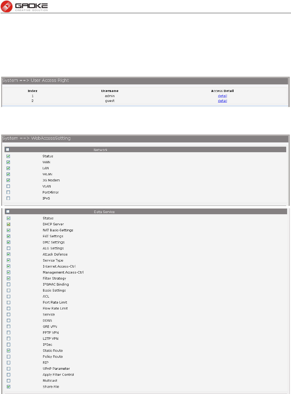
FG7008N User Manual
Page 88 of 111
3.6.10 User Access Right
If the permission level of login user is super, you can see this web page. On this page, you can
change the access right of the user to access the web pages.
Choose the menu System→User Access Right to load the following page.
Figure 3-134 View users
If you want to change the user access right, click detail in the entry to load the following page.
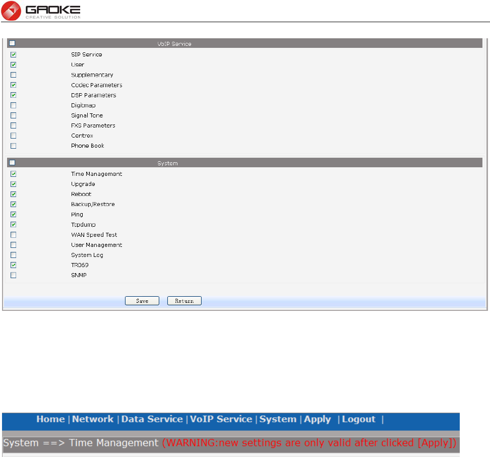
FG7008N User Manual
Page 89 of 111
Figure 3-135 Modify User Access Right
3.7 Apply
Follow the prompts,Some parameters will take effect after click the button of “Apply”.
Figure 3-136 Apply
3.8 Print Function
The device supports to link printer port and provides share printing capabilities to other computers. To
use print function, you need do the following steps.
2. Add Printer
Open the windows of the Control Panel, select Printers and Faxes, and add the printer
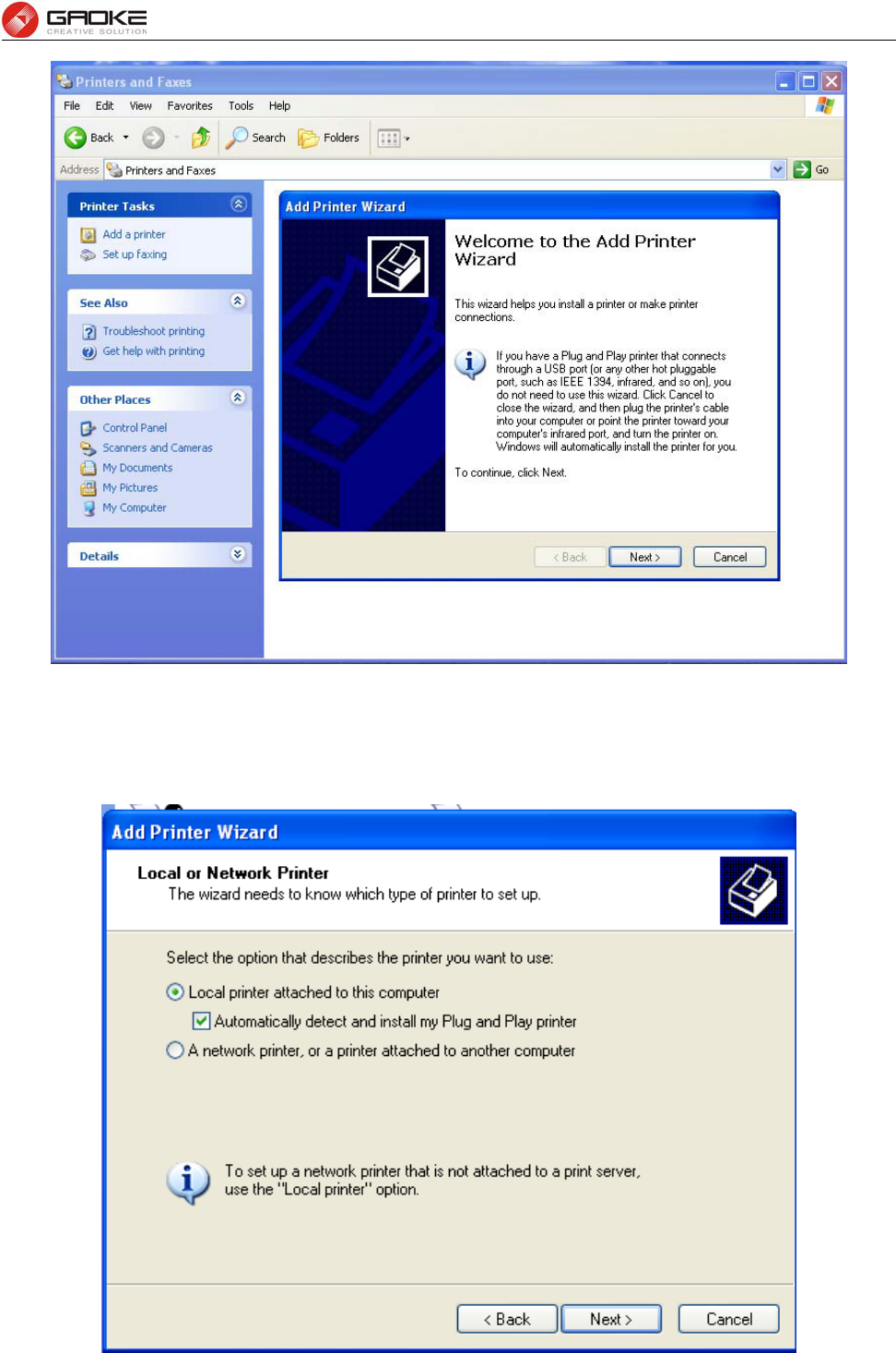
FG7008N User Manual
Page 90 of 111
Figure 3-137 Add Printer
3. Connecting local printer
Select "Local printer attached to this computer."
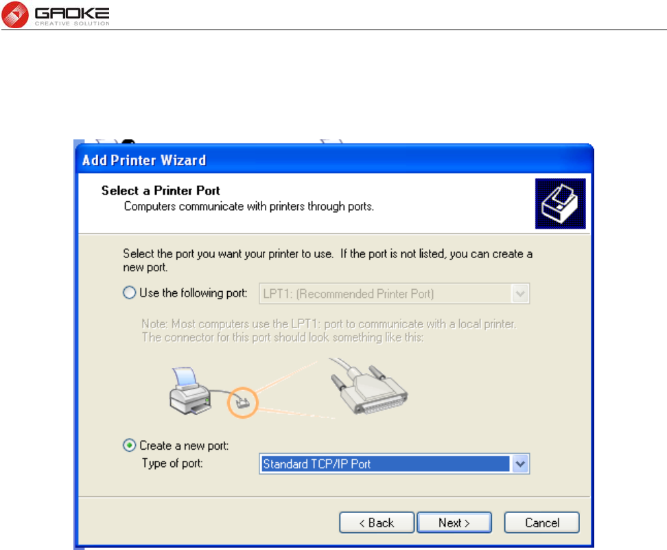
FG7008N User Manual
Page 91 of 111
Figure 3-138 Connecting local printer
4. Create a new port
Select "Create a new port" and select "Standard TCP / IP Port"
Figure 3-139 Create a new port
5. Add print device
Click Next, and add IP devices, assuming the device IP is 192.168.1.1.
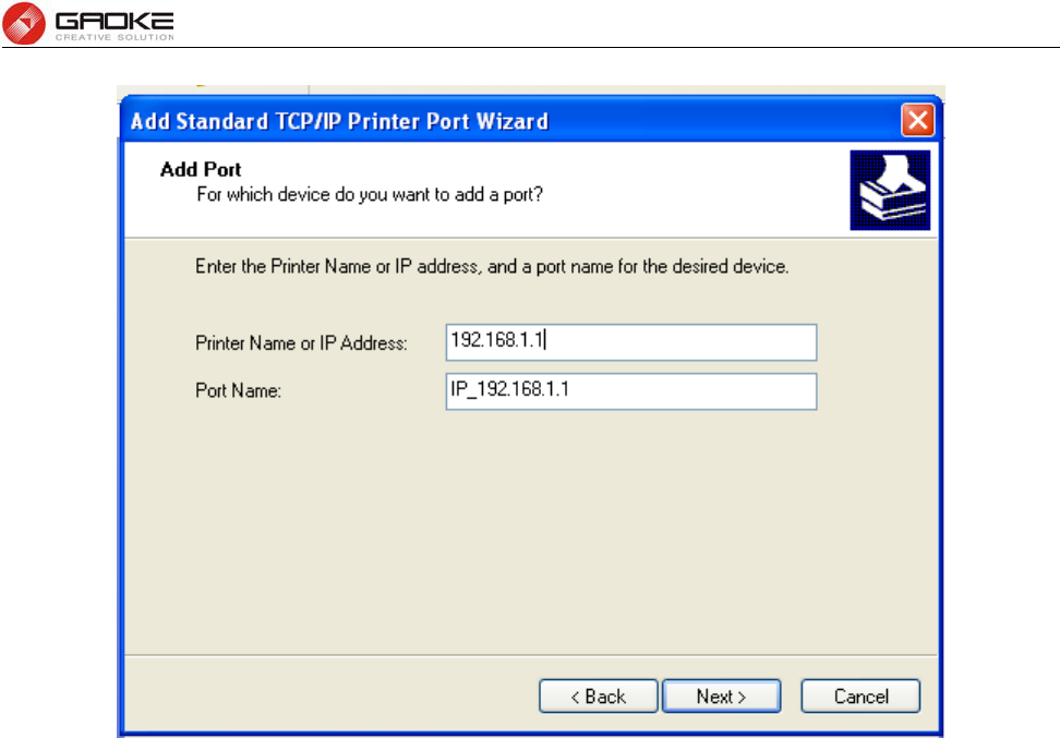
FG7008N User Manual
Page 92 of 111
Figure 3-140 Add IP LAN devices
6. Configure printer port
Select "Custom", click "Settings" to confirm the agreement as "RAW (R)"
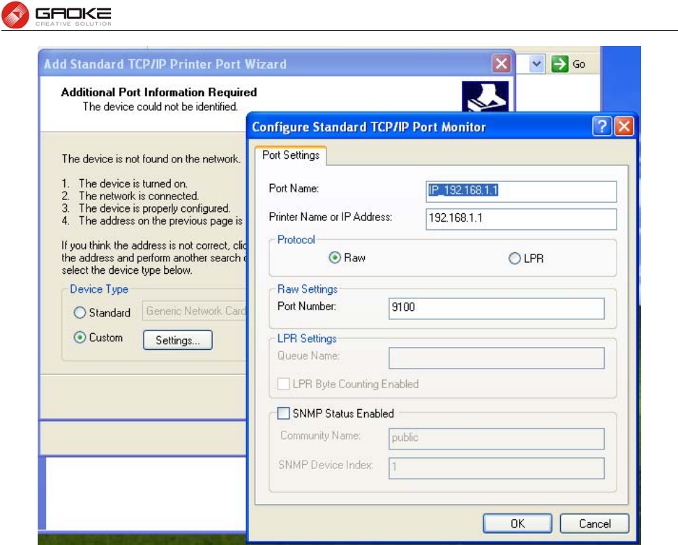
FG7008N User Manual
Page 93 of 111
Figure 3-141 Configuer printer port
7. Add Printer Driver
According to the printer manufacturer and printer type, select the appropriate driver. If the computer has
not printer driver, you need to install the printer driver.
After adding the printer, you can print through the USB printer.
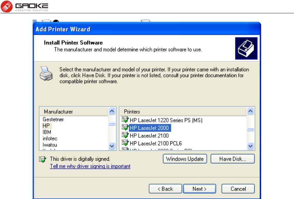
FG7008N User Manual
Page 94 of 111
Figure 3-142 Add Printer Driver
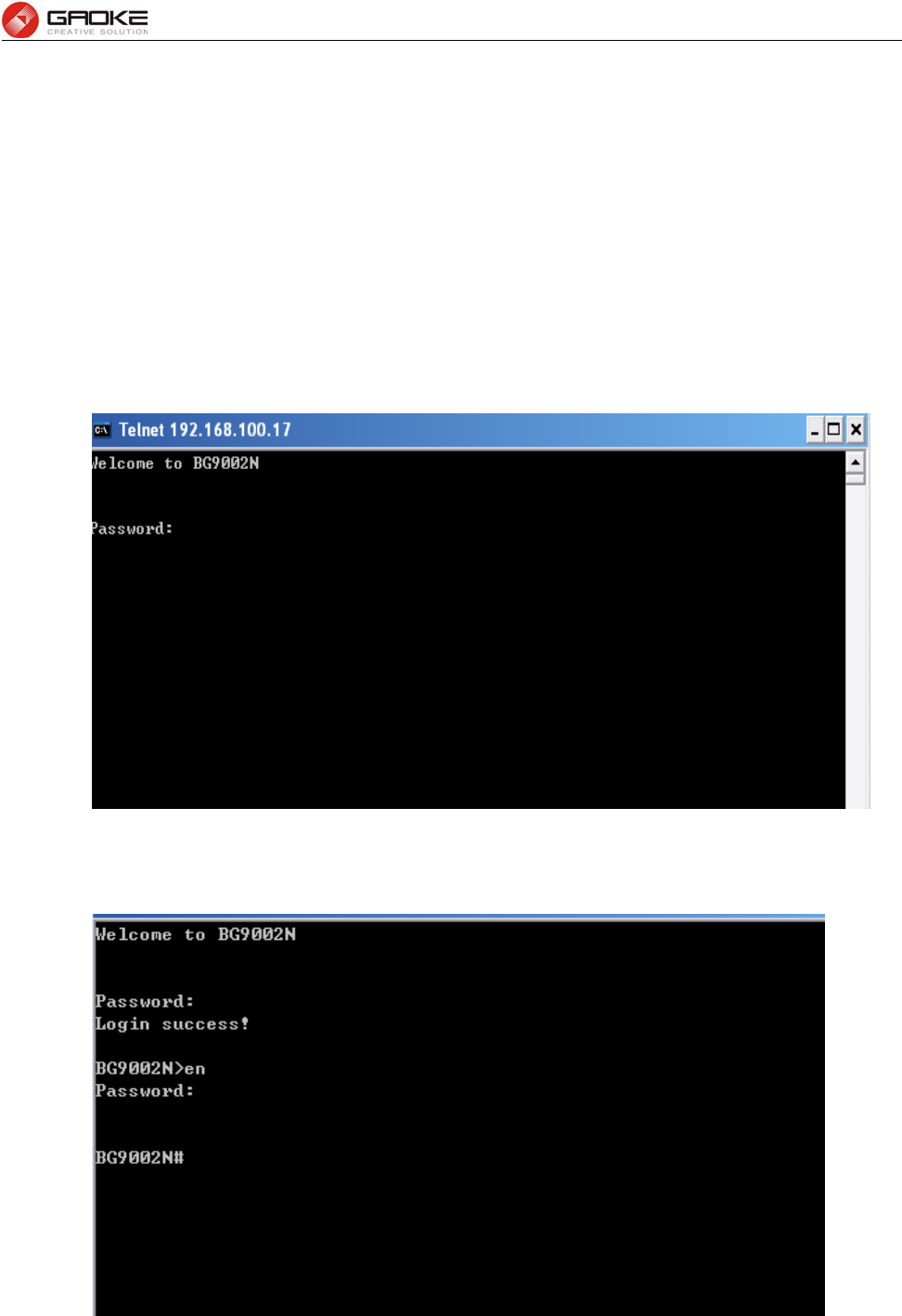
FG7008N User Manual
Page 95 of 111
4 CLI Introduction
4.1 Login
The CLI interface is ready for accessing about one minute after the device powers on. The default
LAN IP address is 192.168.100.1, you can access the CLI interface via either WAN port or LAN port.
Enter telnet with IP address and then press ENTER, you can get access to the Login interface. Such
as IP address is 192.168.100.17, you can input “telnet 192.168.100.17”, and then press ENTER, it
will show as below:
Figure 4-1 Telnet Login
And input the “password” and “en” and the privileged password, you will enter the CLI command
interface:
Figure 4-2 Telnet Command Interface
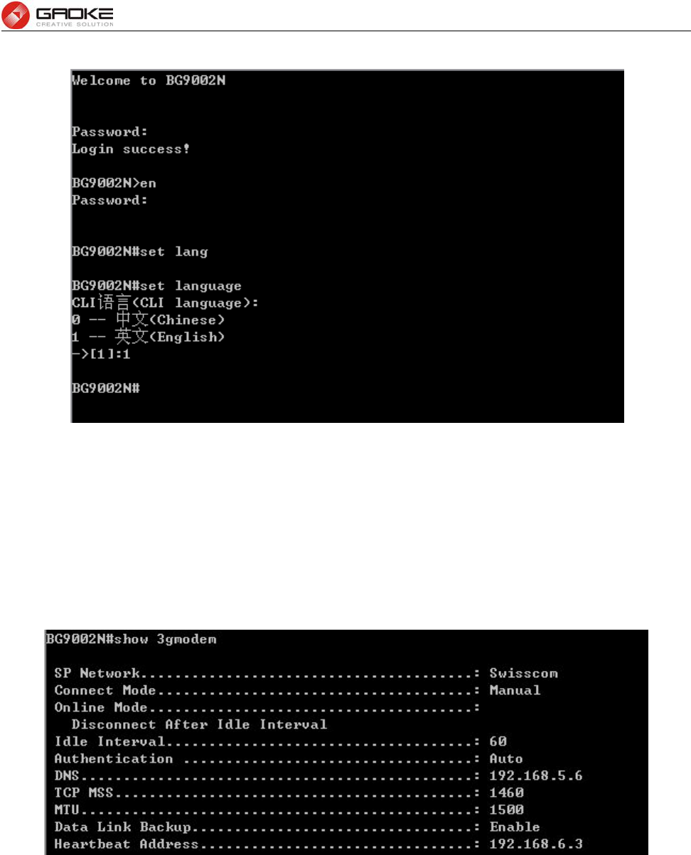
FG7008N User Manual
Page 96 of 111
Input the command “set language” to set the CLI language:
Figure 4-3 Set CLI Language
4.2 Network
4.2.1 3G Modem
The command “show 3gmodem” show the 3G modem information as below:
Figure 4-4 Show 3G Modem Information
The command “set 3gmodem” configure the 3G modem parameters as below.
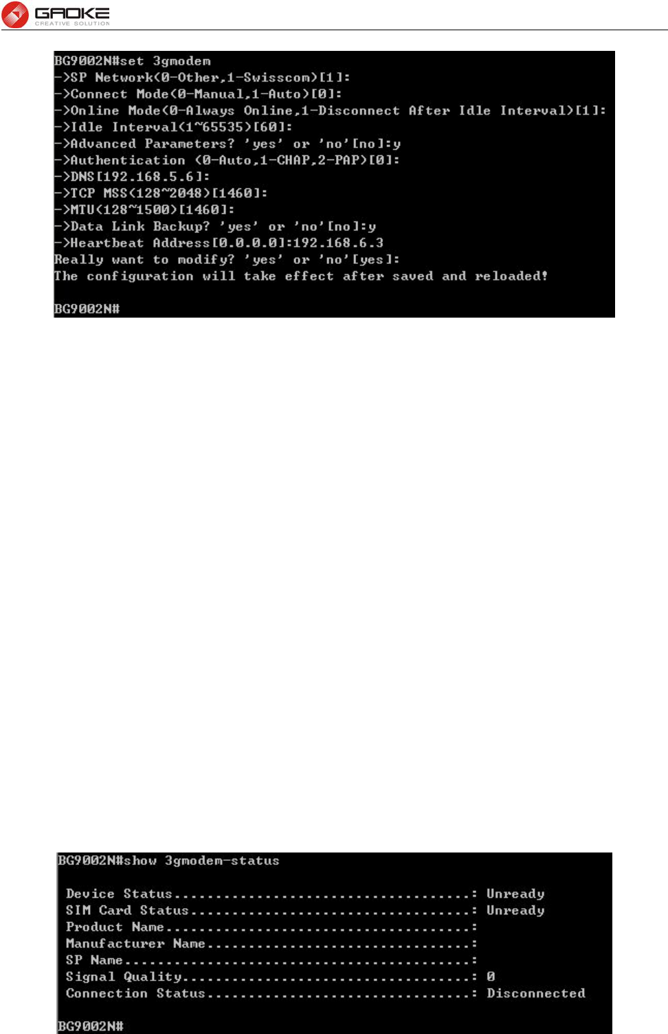
FG7008N User Manual
Page 97 of 111
Figure 4-5 Configure 3G Modem Parameters
The following items are displayed on this screen:
► SP Network: Other or Swisscom. If it is not the target user, you need to select the other.
► Connect Mode: Manual or Auto. The default is Auto.
► Online Mode: always online and disconnect after idle interval. The default is “always online”.
The default idle interval is 60 seconds.
If Other is selected, the following parameters appear:
► Username: 3G network dial-up username.
► Password: 3G network dial-up password.
► Dial Number: 3G network dial numbers.
► APN: 3G network access APN.
► PIN: 3G networks need to use dial-up PIN code, if not, can be set to empty.
Advanced Parameters:
► Authentication: 3G dial-up authentication, CHAP,PAP,Auto are provided. Default is Auto.
► DNS: The default is obtained from the dial-up network devices automatically. You can
also configure DNS manually.
► TCP MSS: Configure TCP maximum segment, we recommend using the default value.
► MTU: Configure 3G link MTU, the default value is recommended
► Data Link Backup: When enabled, if WAN uplink port is disconnected, the routing switches to the 3G
link.
► Heartbeat Address: Set the heartbeat detecting address of the link, the default configuration is not
required.
The command “show 3gmodem-status” show the 3G modem status as below:
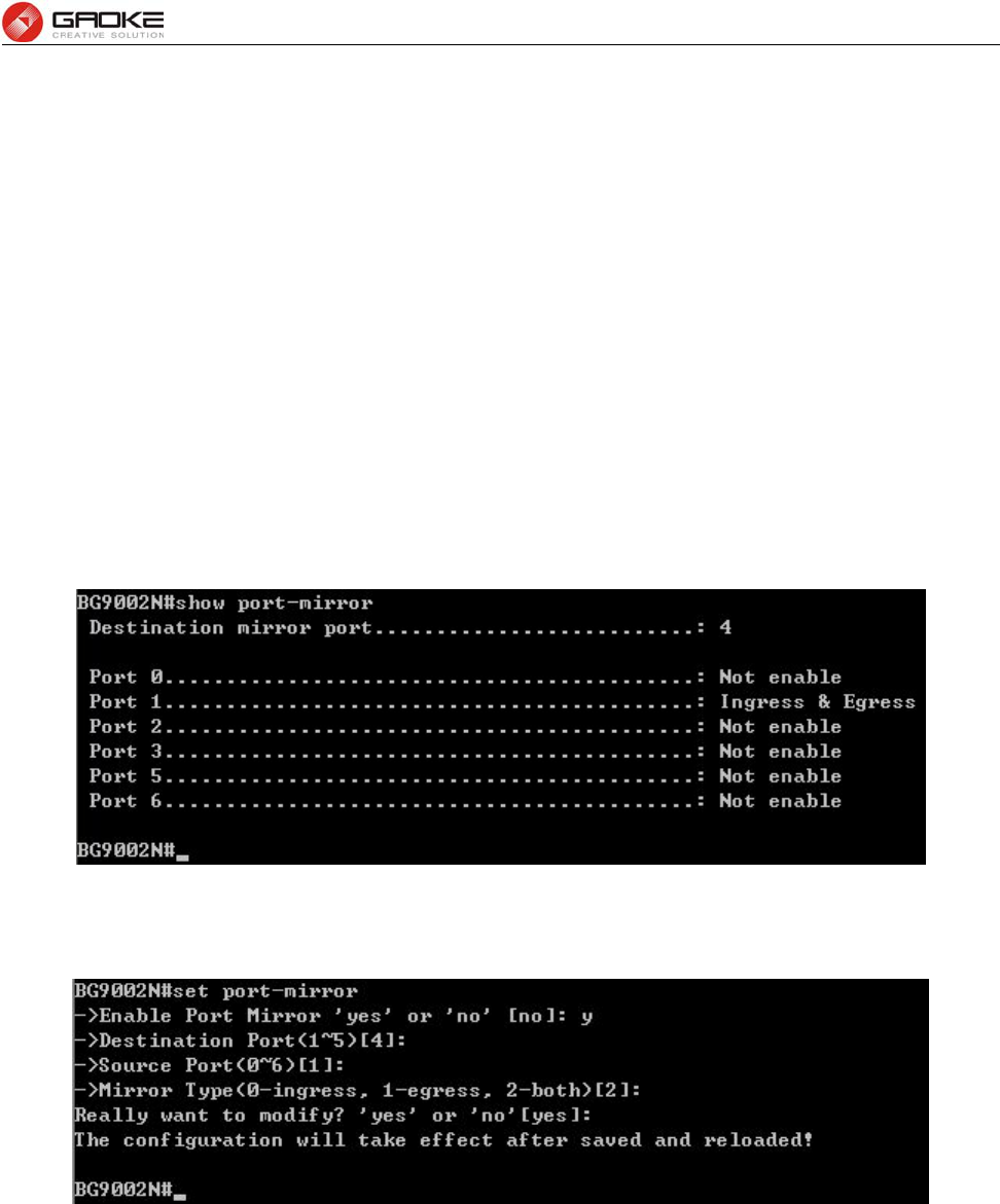
FG7008N User Manual
Page 98 of 111
Figure 4-6 Show 3G Modem Status
The following items are displayed on this screen:
► Device Status: Indicates whether to insert 3G module.
► SIM Card Status: Indicates whether to insert 3G modem in the SIM card, the ready state means
the SIM card is detected.
► Product Name: 3G modem Product Type.
► Manufacturer Name: 3G modem vendor name.
► SP Name: 3G modem service provider name.
► Signal Quality: Signal quality of 3G Modem, up to 31.
► Connection Status: Connected or disconnected.
4.2.2 Port Management
4.2.2.1 Port Mirror
The command “show port-mirror” show the port mirror information as below:
Figure 4-7 Show Port Mirror Information
The command “set port-mirror” configure the port mirror parameters as below.
Figure 4-8 Configure Port Mirror Parameters
The following items are displayed on this screen:
► Enable Port Mirror: Enable or disable port mirror.
► Destination Port: The duplicate of packets from Source Port will send to this destination port.
► Source Port: All packets received from Source Port will be duplicated and the duplicate will
be send to Destination Port.
4.2.2.2 Media Type
The command “show port-status” show the port status information as below:
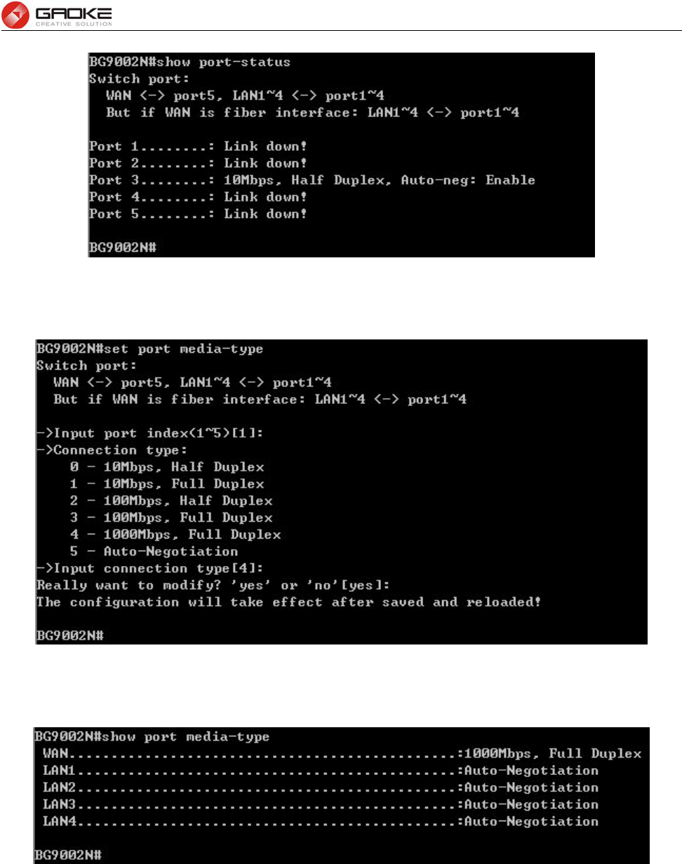
FG7008N User Manual
Page 99 of 111
Figure 4-9 Show Port Status Information
The command “show port media-type” show the port media type information as below:
Figure 4-10 Show Port Media Type Information
The command “set port media-type” configure the port media type parameters as below.
Figure 4-11 Configure Port Media Type Parameters
The following items are displayed on this screen:
► Media Type: provides the following six modes to all physical ports: 10M Half Duplex, 10M Full
Duplex, 100M Half Duplex, 100M Full Duplex, 1000M Full Duplex,
Auto-Negotiation.
► Current Status: Current link status of all physical ports. Read only.
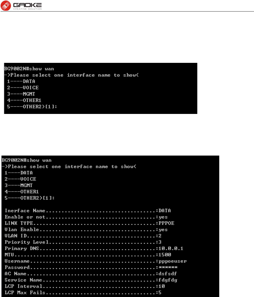
FG7008N User Manual
Page 100 of 111
4.2.3 Wan Parameter
4.2.3.1 Show Wan Parameter
The command “show wan” show the WAN interface configuration as below:
Figure 4-12 Show Wan Parameter
The wan interfaces include DATA、VOICE、MGMT、OTHER1 and OTHER2.
Input “1” to show DATA parameter as below:
Figure 4-13 Show DATA Interface Parameter
Input “2” to show VOICE parameter as below:
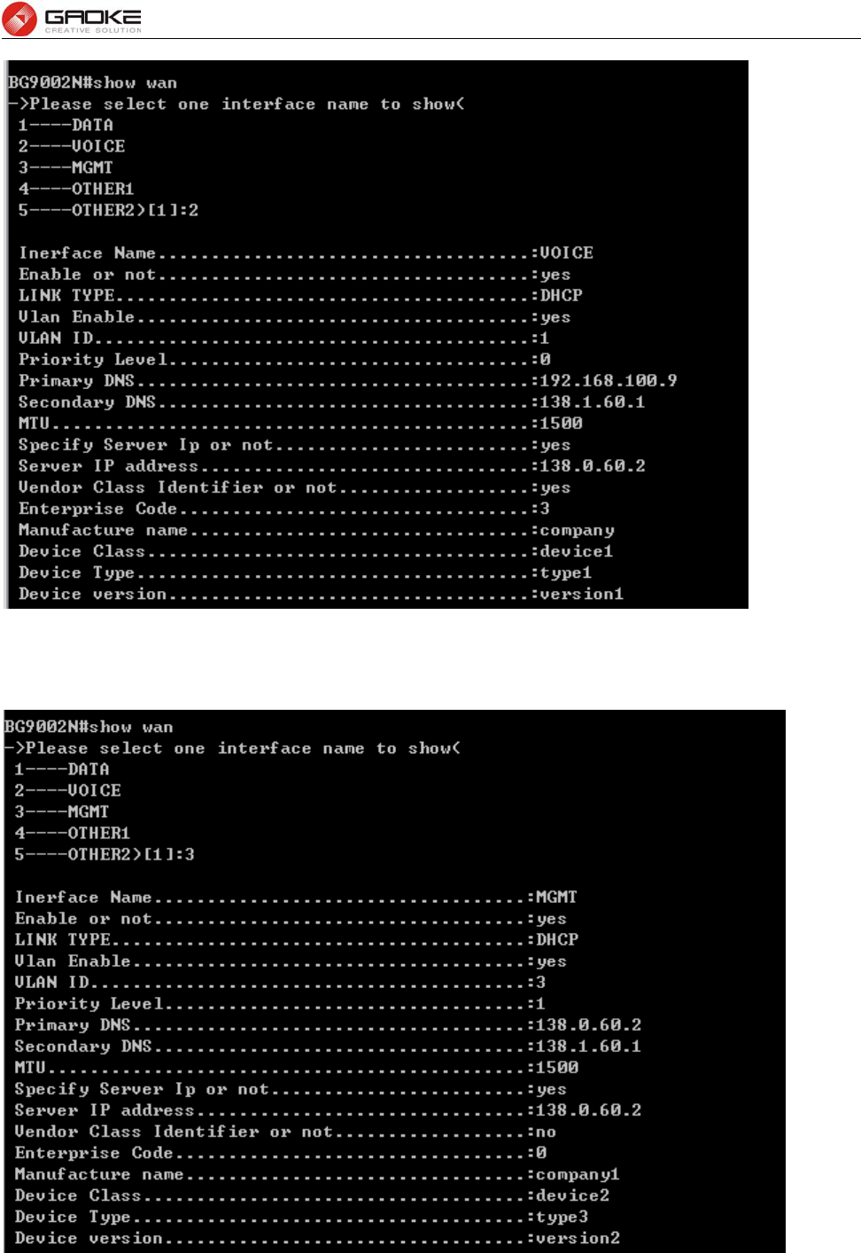
FG7008N User Manual
Page 101 of 111
Figure 4-14 Show VOICE Interface Parameter
Input “3” to show MGMT parameter as below:
Figure 4-15 Show MGMT Interface Parameter
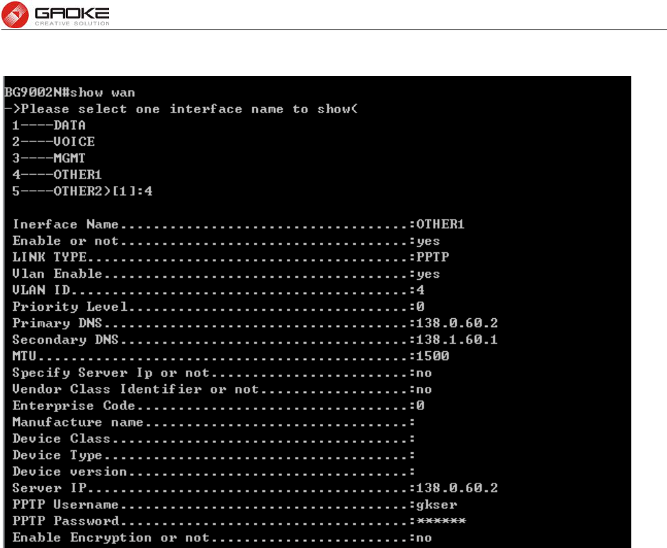
FG7008N User Manual
Page 102 of 111
Input “4” to show OTHER1 parameter as below:
Figure 4-16 Show OTHER1 Interface Parameter
Input “5” to show OTHER2 parameter as below:
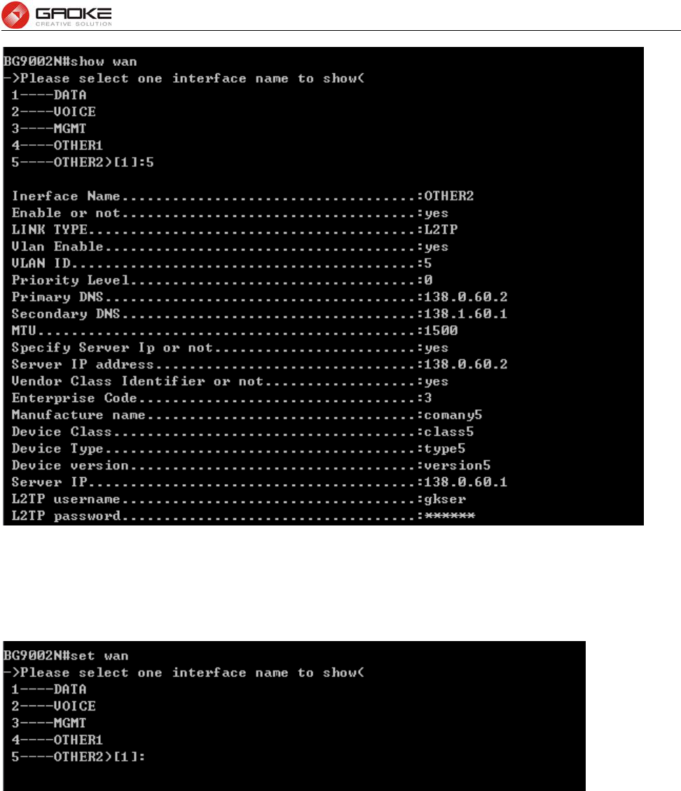
FG7008N User Manual
Page 103 of 111
Figure 4-17 Show OTHER2 Interface Parameter
4.2.3.2 Configure Wan Parameter
The command “set wan” configure the wan interface parameter as below:
Figure 4-18 Configure WAN Parameter
The wan interfaces include DATA、VOICE、MGMT、OTHER1 and OTHER2.
Input “1” to configure DATA parameter as below:
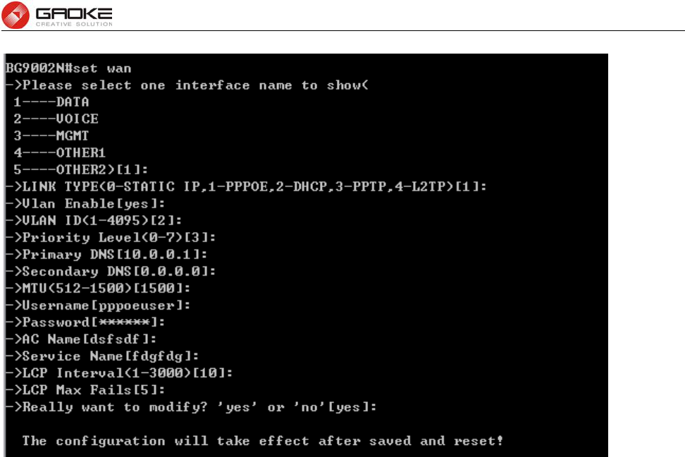
FG7008N User Manual
Page 104 of 111
Figure 4-19 Configure DATA Interface Parameter
The following items are displayed on this screen:
► Enable: Enable this WAN interface (DATA can’t be disabled).
► Type: Select PPPoE if your ISP provides xDSL Virtual Dial-up connection.
► VLAN Enable: Optional. Enable VLAN to configure VLAN ID and VLAN Priority Level.
► VLAN ID: Optional. VLAN ID of this WAN interface.
► Priority Level: Optional. VLAN Priority Level of this WAN interface.
► Primary DNS: Enter the IP address of your ISP’s Primary DNS (Domain Name Server)
manually. If you are not clear, please consult your ISP. It’s not allowed to
access the Internet via domain name if the Primary DNS field is blank.
► Secondary DNS: Optional. If a Secondary DNS Server address is available, enter it.
► Username: Enter the Account Name provided by your ISP. If you are not clear, please
consult your ISP.
► Password: Enter the Password provided by your ISP.
► Service Name /AC Name: Optional. The service name and AC (Access Concentrator) name, which
should not be configured unless you are sure it is necessary for your ISP. In
most cases, leaving these fields blank will work.
► LCP Interval: PPPoE will send an LCP echo-request frame to the peer every LCP interval
seconds.
► LCP Max Fails: PPPoE will presume the peer to be dead if LCP Max Fails LCP echo-requests
are send without receiving a valid LCP echo-reply.
Input “2” to configure VOICE parameter as below:
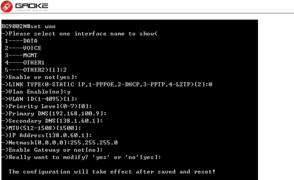
FG7008N User Manual
Page 105 of 111
Figure 4-20 Configure VOICE Interface Parameter
The following items are displayed on this screen:
► Enable: Enable this WAN interface (DATA can’t be disabled).
► Type: Select Static IP if your ISP has assigned a static IP address for your.
► VLAN Enable: Optional. Enable VLAN to configure VLAN ID and VLAN Priority Level.
► VLAN ID: Optional. VLAN ID of this WAN interface.
► Priority Level: Optional. VLAN Priority Level of this WAN interface.
► Primary DNS: Enter the IP address of your ISP’s Primary DNS (Domain Name Server). If you are
not clear, please consult your ISP. It’s not allowed to access the Internet via
domain name if the Primary DNS field is blank.
► Secondary DNS: Optional. If a Secondary DNS Server address is available, enter it.
► IP Address: Enter the IP address assigned by your ISP. If you are not clear, please consult your
ISP.
► Netmask: Enter the Subnet Mask assigned by your ISP.
► Gateway: Optional. Enter the Gateway assigned by your ISP.
Input “3” to configure MGMT parameter as below:
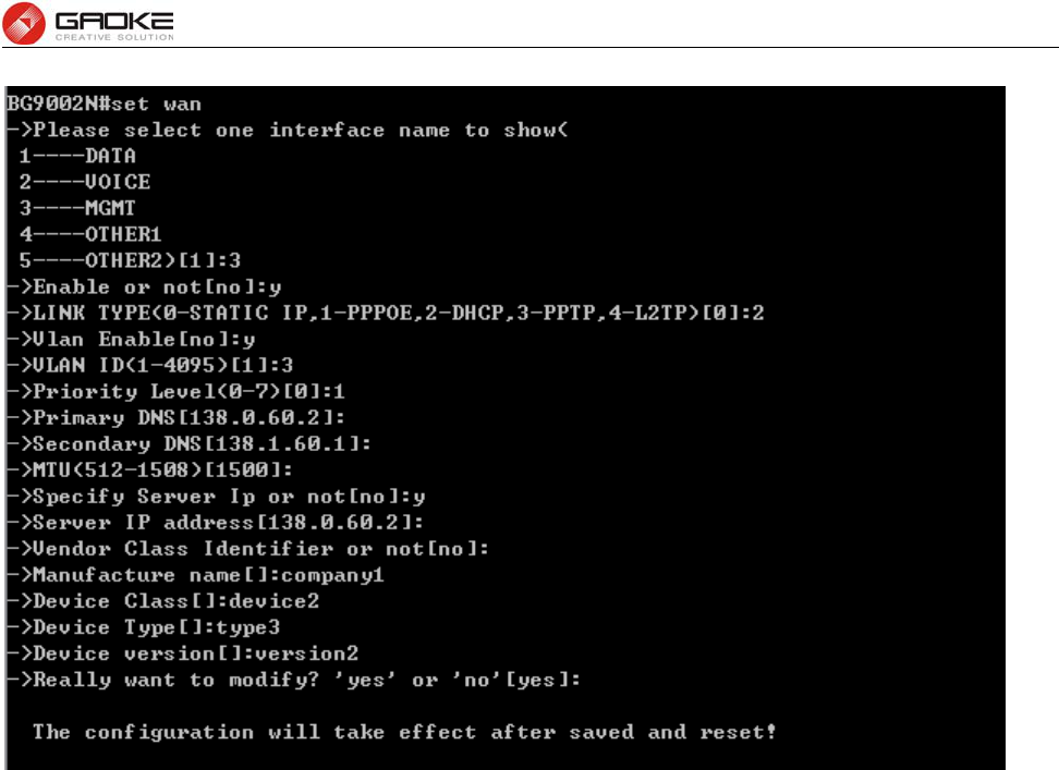
FG7008N User Manual
Page 106 of 111
Figure 4-21 Configure MGMT Interface Parameter
The following items are displayed on this screen:
► Enable: Enable this WAN interface (DATA can’t be disabled).
► Type: Select DHCP if your ISP assigns the IP address automatically.
► VLAN Enable: Optional. Enable VLAN to configure VLAN ID and VLAN Priority Level.
► VLAN ID: Optional. VLAN ID of this WAN interface.
► Priority Level: Optional. VLAN Priority Level of this WAN interface.
► Primary DNS: Enter the IP address of your ISP’s Primary DNS (Domain Name Server)
manually. If you are not clear, please consult your ISP. It’s not allowed to
access the Internet via domain name if the Primary DNS field is blank.
► Secondary DNS: Optional. If a Secondary DNS Server address is available, enter it.
► Appoint Server IP: Optional. If network has multiple DHCP servers, enter the IP address of your
ISP’S DHCP server
► Vendor Class Identifier: Optional. This option (60) is used by DHCP clients to optionally identify the
vendor type and configuration of a DHCP client.
► Enterprise Code: Optional.
► Manufacture Name: Optional.
► Device Class: Optional.
► Device Type: Optional.
► Device Version: Optional.
Input “4” to configure OTHER1 parameter as below:
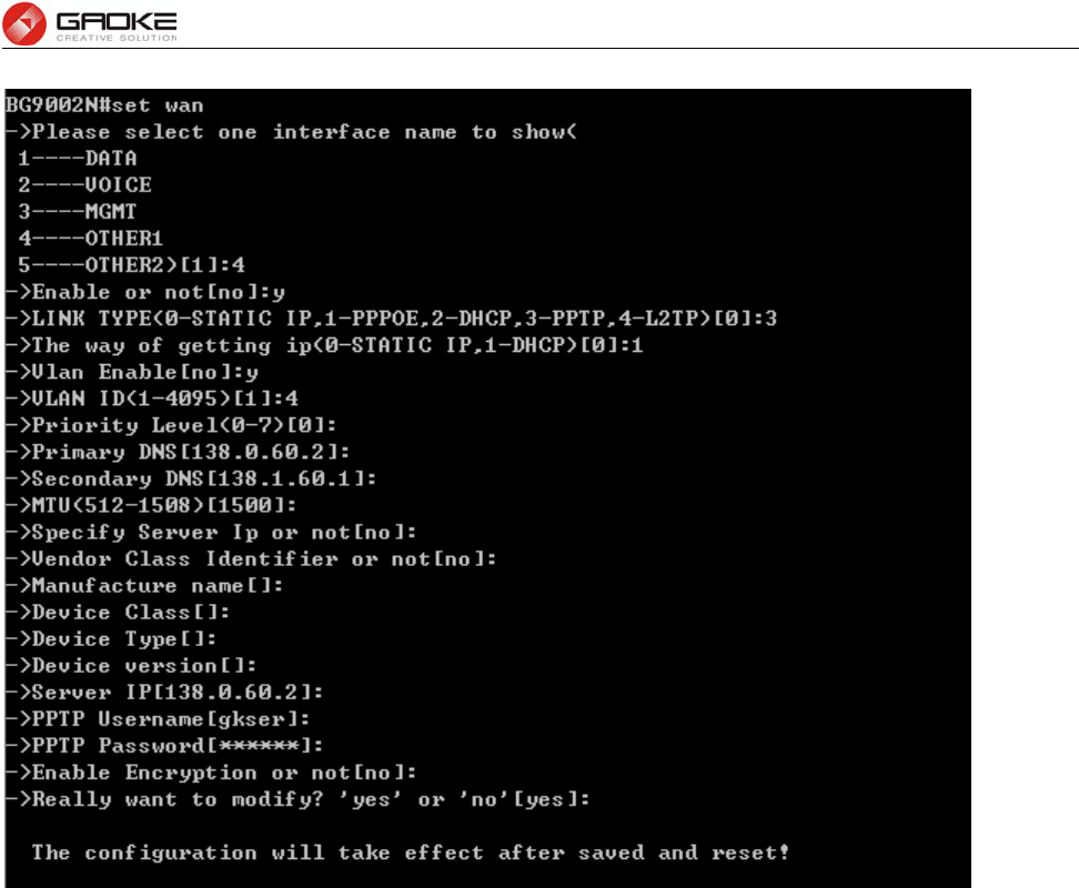
FG7008N User Manual
Page 107 of 111
Figure 4-22 Configure OTHER1 Interface Parameter
The following items are displayed on this screen:
► Enable: Enable this WAN interface (DATA can’t be disabled).
► Type: Select PPTP if your ISP provides a PPTP connection.
► VLAN Enable: Optional. Enable VLAN to configure VLAN ID and VLAN Priority Level.
► VLAN ID: Optional. VLAN ID of this WAN interface.
► Priority Level: Optional. VLAN Priority Level of this WAN interface.
► Primary DNS: Enter the IP address of your ISP’s Primary DNS (Domain Name Server)
manually. If you are not clear, please consult your ISP. It’s not allowed to
access the Internet via domain name if the Primary DNS field is blank.
► Secondary DNS: Optional. If a Secondary DNS Server address is available, enter it.
► Server IP: Enter the Server IP provided by your ISP.
► Username: Enter the Account Name provided by your ISP. If you are not clear, please
consult your ISP.
► Password: Enter the Password provided by your ISP.
► Enable Encryption: Enable PPTP link encryption.
Secondary Connection: Here allow you to configure the secondary connection. DHCP and Static IP
connection types are provided.
If Static is selected:
► IP Address: If Static IP is selected, configure the IP address of WAN port.
► Netmask: If Static IP is selected, configure the subnet mask of WAN port.
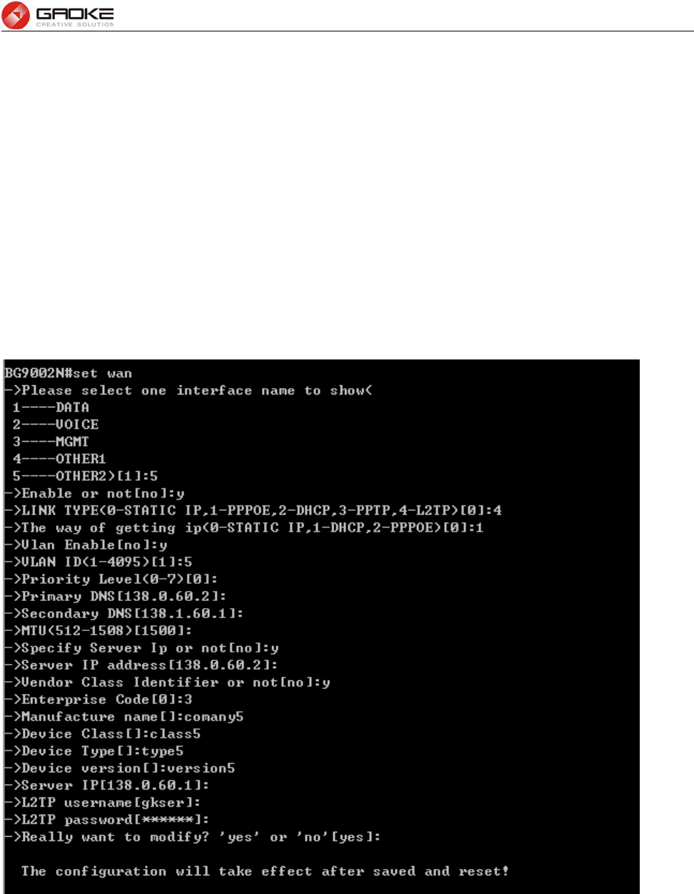
FG7008N User Manual
Page 108 of 111
► Gateway: Optional. If Static IP is selected, configure the default gateway of WAN port.
If DHCP is selected:
► Appoint Server IP: Optional. If network has multiple DHCP servers, enter the IP address of your
ISP’s DHCP server.
►Vendor Class Identifier: Optional. This option (60) is used by DHCP clients to optionally identify the
vendor type and configuration of a DHCP client.
► Enterprise Code: Optional.
► Manufacture Name: Optional.
► Device Class: Optional.
► Device Type: Optional.
► Device Version: Optional.
Input “5” to configure OTHER2 parameter as below:
Figure 4-23 Configure OTHER2 Interface Parameter
The following items are displayed on this screen:
► Enable: Enable this WAN interface (DATA can’t be disabled).
► Type: Select L2TP if your ISP provides a L2TP connection.
► VLAN Enable: Optional. Enable VLAN to configure VLAN ID and VLAN Priority Level.
► VLAN ID: Optional. VLAN ID of this WAN interface.
► Priority Level: Optional. VLAN Priority Level of this WAN interface.
► Primary DNS: Enter the IP address of your ISP’s Primary DNS (Domain Name Server). If
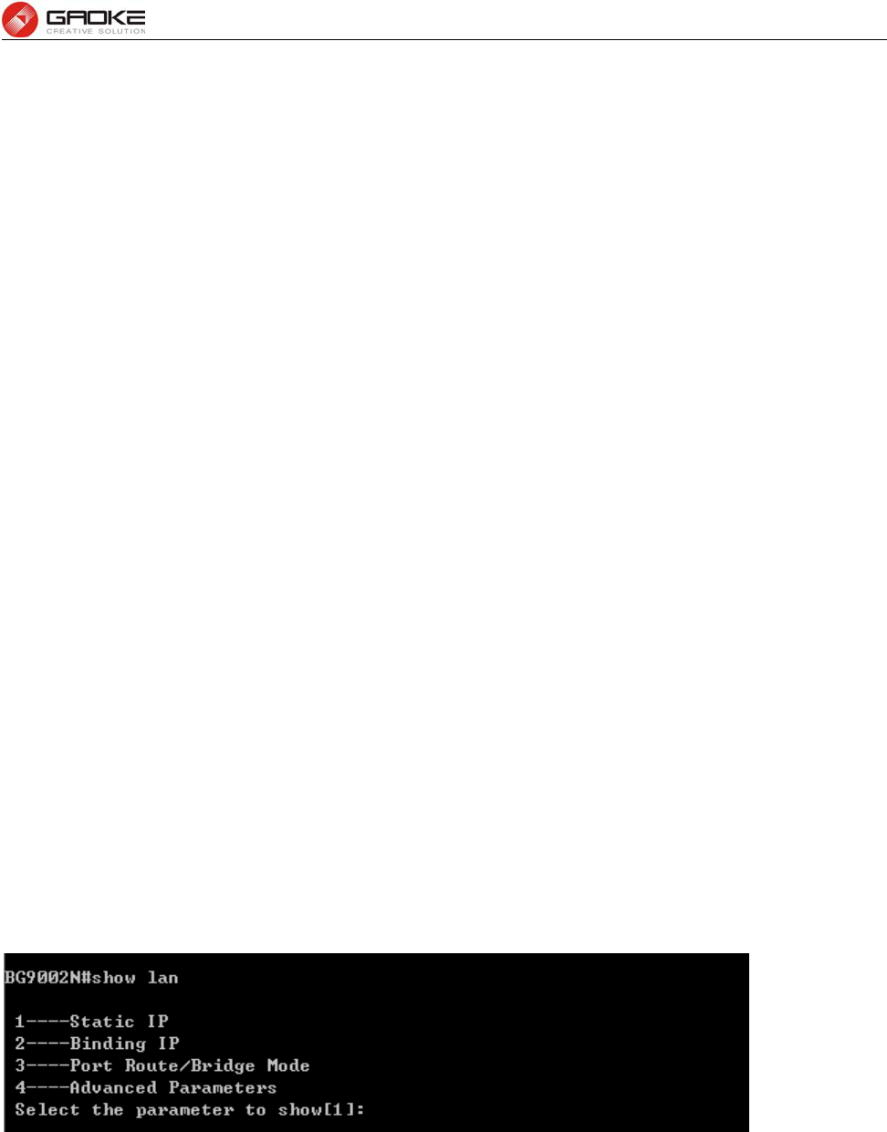
FG7008N User Manual
Page 109 of 111
you are not clear, please consult your ISP. It’s not allowed to access the
Internet via domain name if the Primary DNS field is blank.
► Secondary DNS: Optional. If a Secondary DNS Server address is available, enter it.
► Server IP: Enter the Server IP provided by your ISP.
► Username: Enter the Account Name provided by your ISP. If you are not clear, please
consult your ISP.
► Password: Enter the Password provided by your ISP.
Secondary Connection: Here allow you to configure the secondary connection. DHCP and Static IP
connection types are provided.
If Static is selected:
► IP Address: If Static IP is selected, configure the IP address of WAN port.
► Netmask: If Static IP is selected, configure the subnet mask of WAN port.
► Gateway: Optional. If Static IP is selected, configure the default gateway of WAN port.
If DHCP is selected:
► Appoint Server IP: Optional. If network has multiple DHCP servers, enter the IP address of your
ISP’s DHCP server.
►Vendor Class Identifier: Optional. This option (60) is used by DHCP clients to optionally identify the
vendor type and configuration of a DHCP client.
► Enterprise Code: Optional.
► Manufacture Name: Optional.
► Device Class: Optional.
► Device Type: Optional.
► Device Version: Optional.
4.2.4 Lan Parameter
4.2.4.1 Show Lan Parameter
The command “show lan” show the LAN configuration as below:
Figure 4-24 Show LAN Parameter
Input “1” to show LAN static IP confguration as below:
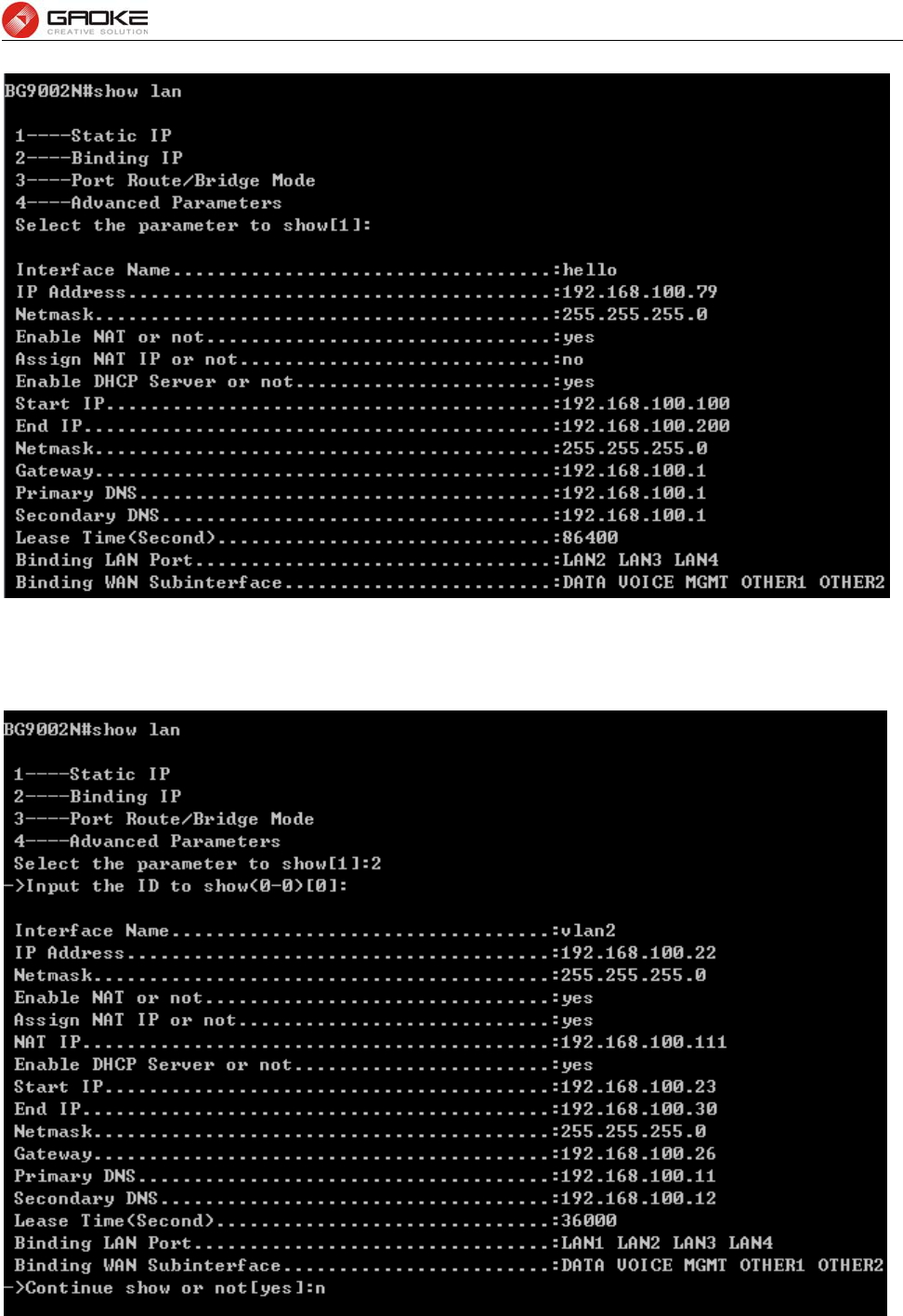
FG7008N User Manual
Page 110 of 111
Figure 4-25 Show Static IP Parameter
Input “2” to show binding IP configuration as below:
Figure 4-26 Show Binding IP Parameter
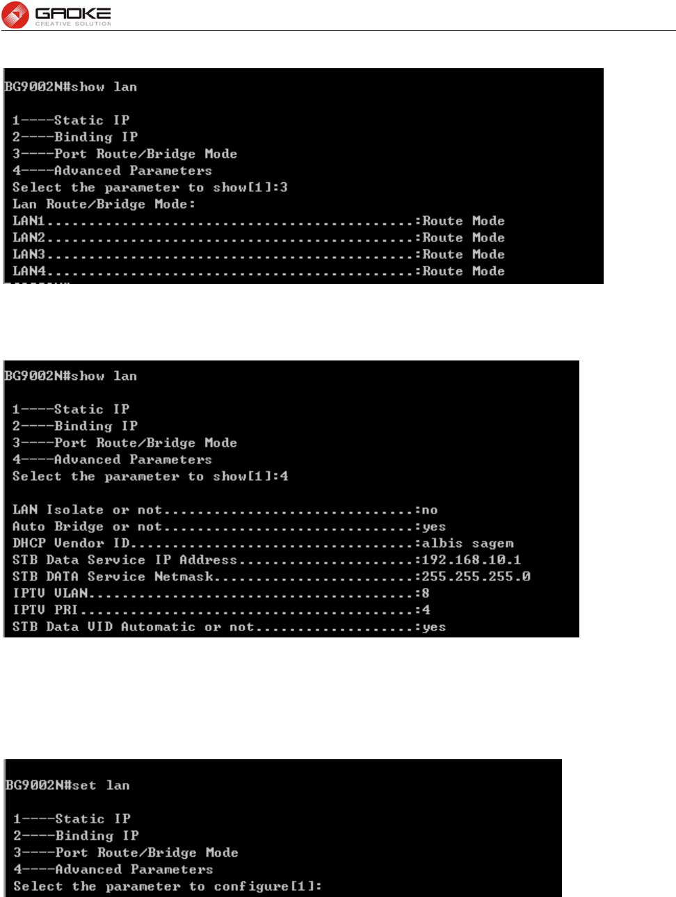
FG7008N User Manual
Page 111 of 111
Input “3” to show port route/bridge mode as below:
Figure 4-27 Show Port Mode Parameter
Input “4” to show advanced parameters as below:
Figure 4-28 Show Advanced Parameter
4.2.4.2 Configure Lan Parameter
The command “set lan” configure the LAN parameter as below:
Figure 4-29 Configure LAN Parameter
Input “1” to configure static IP as below:
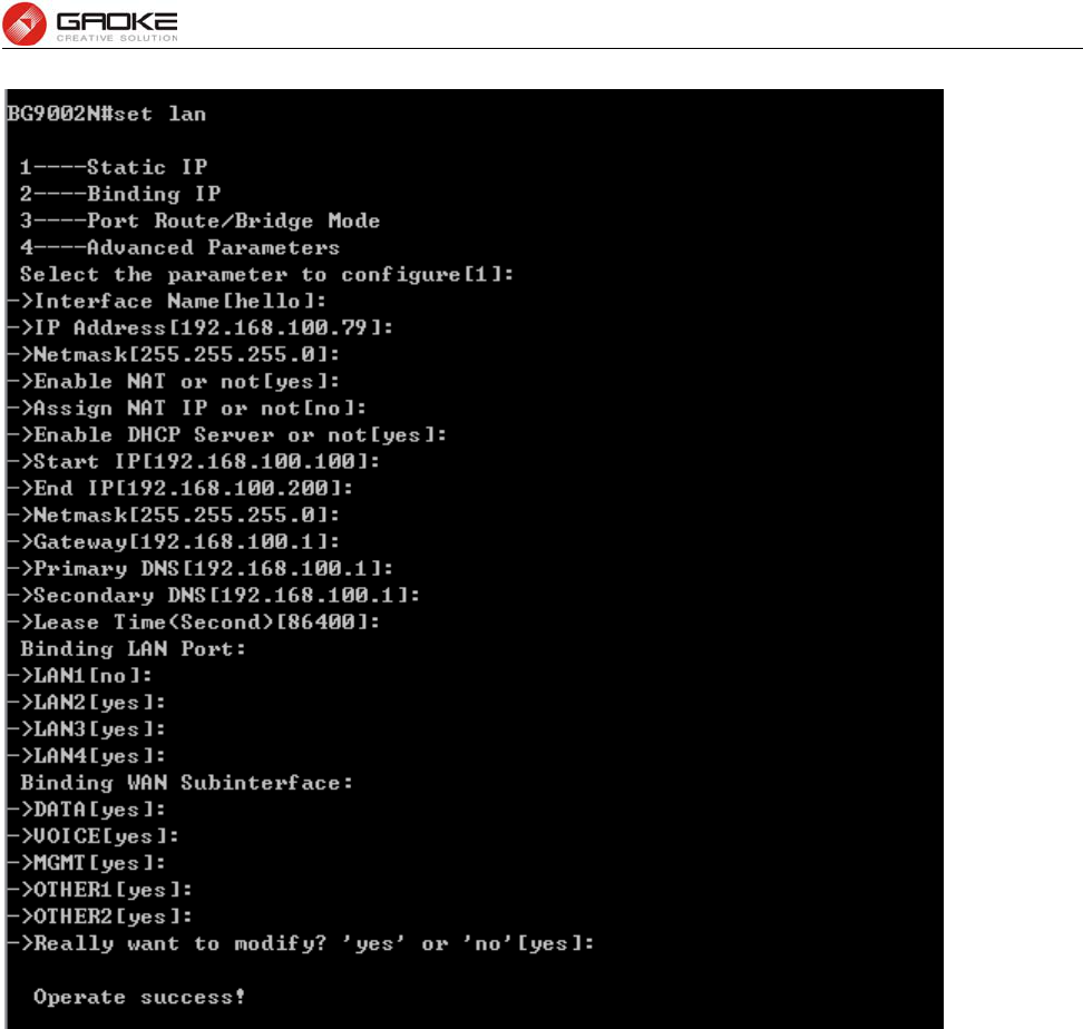
FG7008N User Manual
Page 112 of 111
Figure 4-30 Configure Static IP Parameter
The following items are displayed on this part.
► Interface Name: Name of this LAN interface.
► IP Address: Enter the IP address for this LAN interface.
► Netmask: Enter the subnet mask for this LAN interface.
► NAT: Optional Enable or disable NAT for this LAN interface
► Assign NAT IP: Optional If NAT is selected. NAT IP address can be assigned.
► Enable DHCP Server: Enable or disable DHCP server on this LAN interface.
► Start IP: If Enable DHCP Server is selected, enter the Start IP address to define a
range for the DHCP server to assign dynamic IP addresses. This address
should be in the same IP address subnet with the IP address of this LAN
interface.
► End IP: If Enable DHCP Server is selected, enter the End IP address to define a
range for the DHCP server to assign dynamic IP addresses. This address
should be in the same IP address subnet with the IP address of this LAN
interface.
► Netmask: If Enable DHCP Server is selected, enter the Netmask to define a range for
the DHCP server to assign dynamic IP addresses.
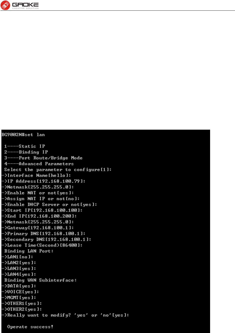
FG7008N User Manual
Page 113 of 111
► Gateway: Optional .If Enable DHCP Server is selected, enter the Gateway address to
be assigned.
► Primary DNS: Optional. If Enable DHCP Server is selected, enter the Primary DNS server
address to be assigned.
► Secondary DNS: Optional. If Enable DHCP Server is selected, enter the Secondary DNS
server address to be assigned.
► Lease Time(Second): If Enable DHCP Server is selected, specify the length of time the DHCP
server will reserve the IP address for each client. After the IP address
expired, the client will be automatically assigned a new one.
► Binding LAN Port: Select the physical LAN port to bind the IP address of this LAN interface.
► Binding WAN Subinterface: Select the WAN subinterface which the packet from this LAN interface
can be sending to.
Input “2” to configure binding IP as below:
Figure 4-31 Configure Binding IP Parameter
Input “3” to configure port route/bridge mode as below:
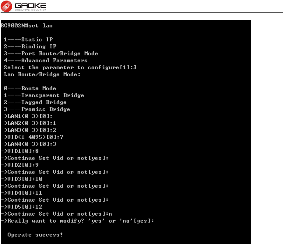
FG7008N User Manual
Page 114 of 111
Figure 4-32 Configure Port Mode Parameter
The following items are displayed on this part.
► Port: The physical LAN port name (LAN1~LAN4).
► Route/Bridge: Mode of this physical LAN port. The following four modes are provided:
Route: route to WAN
Transparent bridge: not modify the packets;
Tagged bridge: LAN untagged, WAN tagged; only 1 VID supported
Promisc Mode: Tagged packets in bridge mode, untagged packets in route mode;
most 5 VIDs supported (e.g. 8, 10, 13).
► VLAN ID List: If Tagged bridge/Promisc Mode is selected, configure the VID/VIDs.
Input “4” to configure advanced parameters as below:
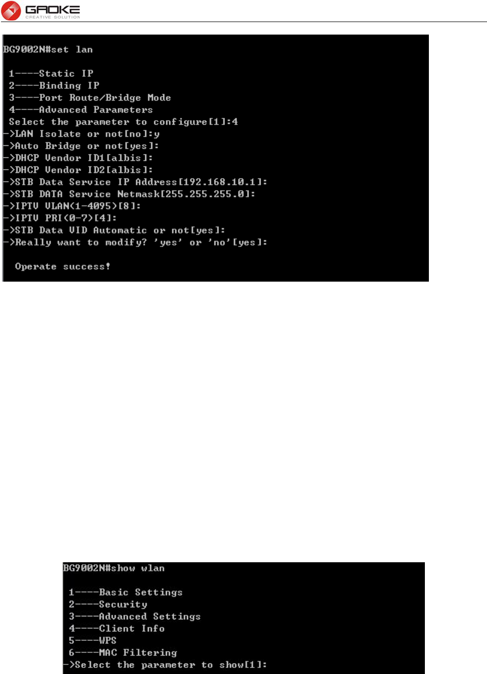
FG7008N User Manual
Page 115 of 111
Figure 4-33 Configure Advanced Parameter
The following items are displayed on this part.
► LAN Isolate: Check the box to prohibit the access between LAN interfaces.
► Auto Bridge: Check the box to dynamically create IPTV bridge for STB.
► DHCP Vendor ID: Vendor class identifier List (DHCP 60 option), support at most two vendor IDs.
► IPAddress: IP address of interface for STB data service.
► Netmask: Subnet mask of interface for STB data service.
► VID: VID of IPTV VLAN.
► PRI: Priority level of IPTV VLAN.
► Automatic: Check the box to automatically detect the VID of STB data service.
4.2.5 WLAN
4.2.5.1 Show WLAN Parameter
The command “show wlan” show the WLAN configuration as below:
Figure 4-34 Show WLAN Parameter
Input “1” to show basic settings as below:
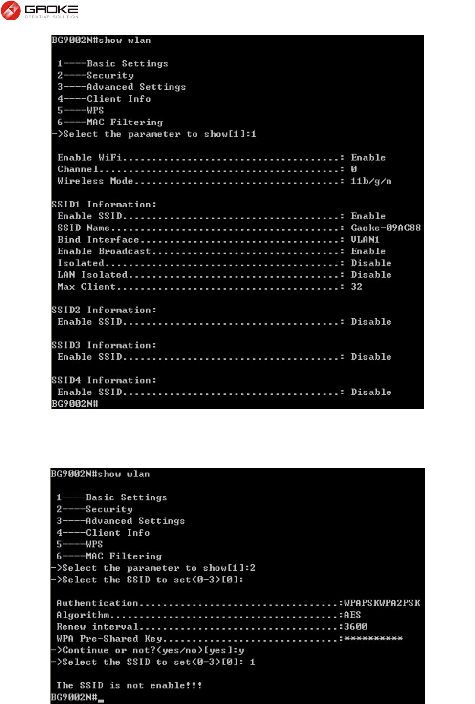
FG7008N User Manual
Page 116 of 111
Figure 4-35 Show Basic Settings
Input “2” to show security configuration as below:
Figure 4-36 Show Security Parameter
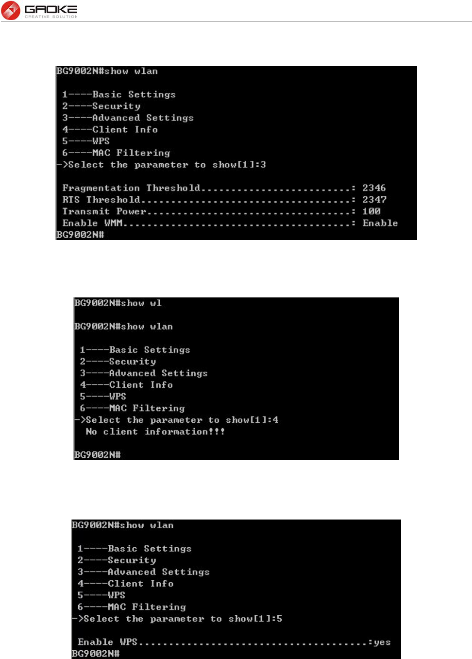
FG7008N User Manual
Page 117 of 111
Input “3” to show advanced settings as below:
Figure 4-37 Show Advanced Settings
Input “4” to show client information as below:
Figure 4-38 Show Client Information
Input “5” to show WPS configuration as below:
Figure 4-39 Show WPS Parameter
Input “6” to show MAC filtering configuration as below:
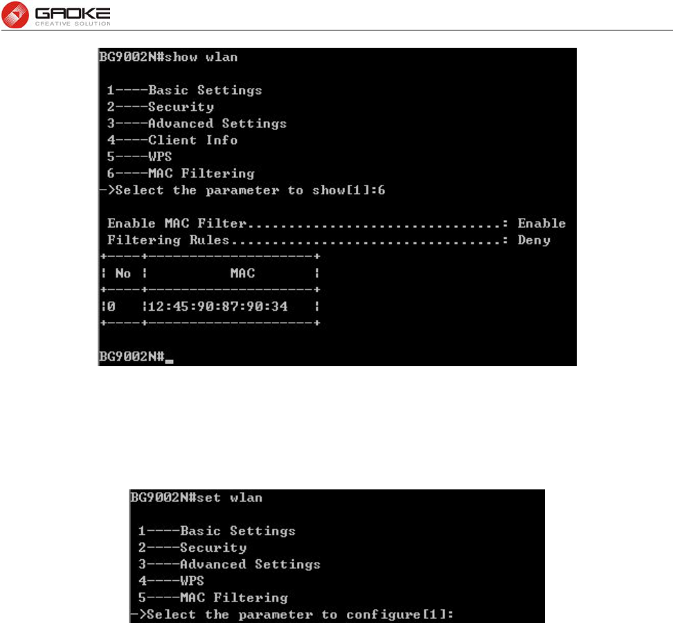
FG7008N User Manual
Page 118 of 111
Figure 4-40 Show MAC Filtering Parameter
4.2.5.2 Configure WLAN Parameter
The command “set wlan” configure the WLAN parameter as below:
Figure 4-41 Configure WLAN Parameter
Input “1” to configure basic settings as below: