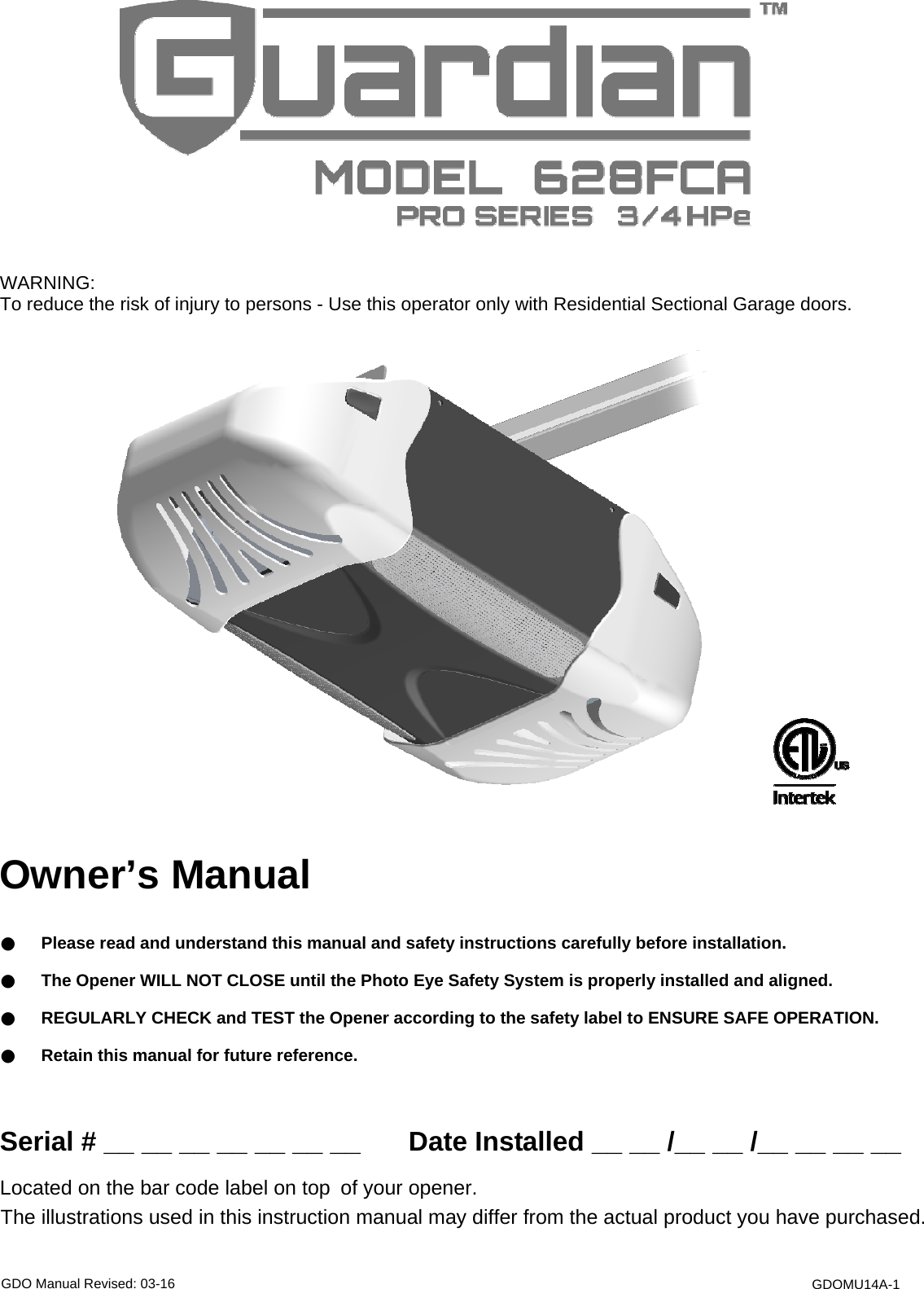
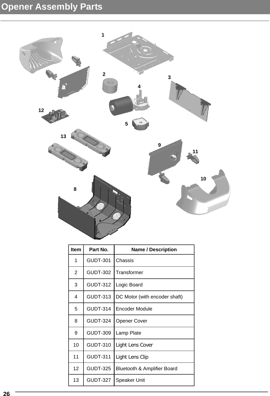
GUARDIAN 303RX-MBT Garage Door Opener User Manual
GUARDIAN SHANGHAI CORP. Garage Door Opener Users Manual
UserManual.wiki
>
GUARDIAN
>
303RX MBT User Manual
Users Manual
Navigation menu
Upload a User Manual
Namespaces
Wiki Guide
HTML
PDF
Info
Views
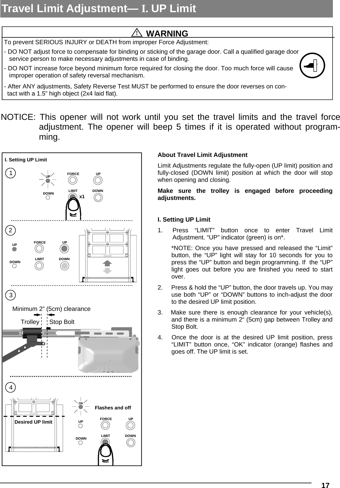
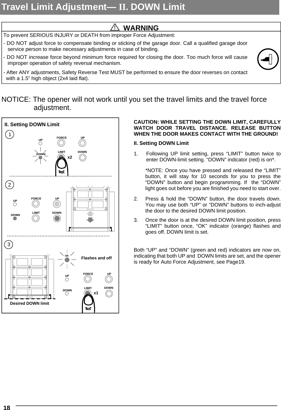
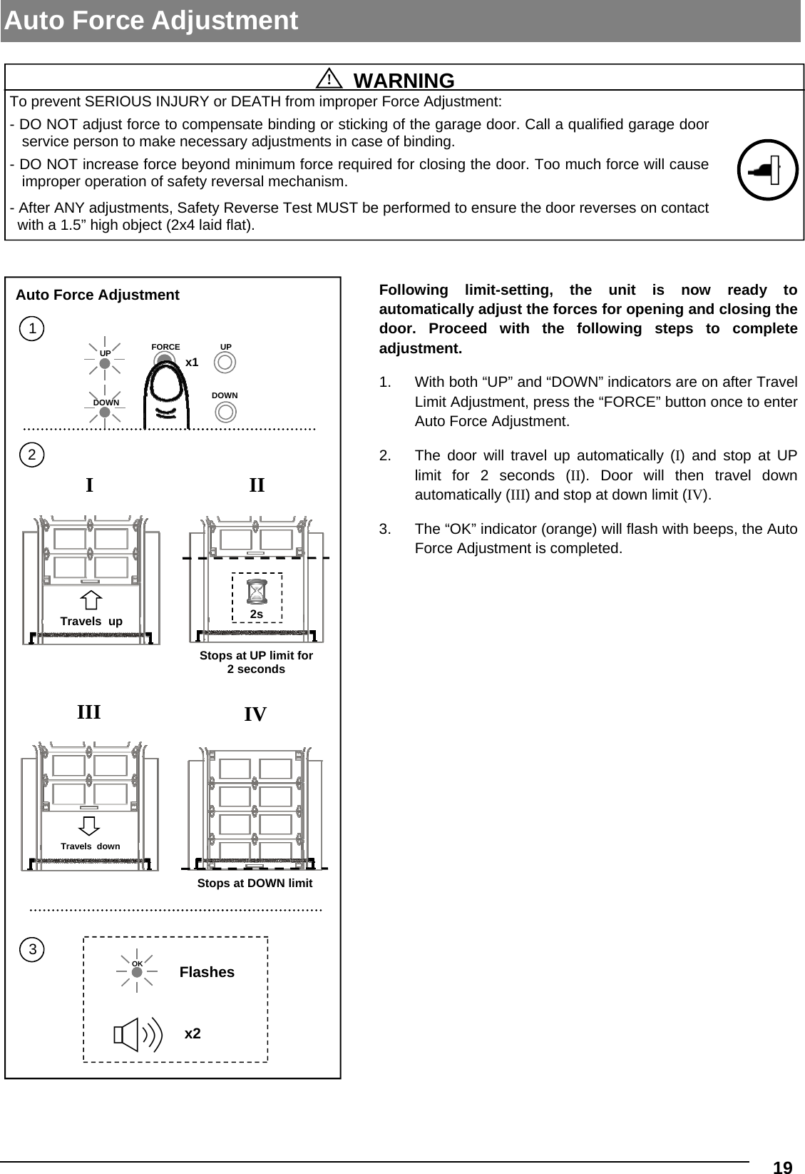
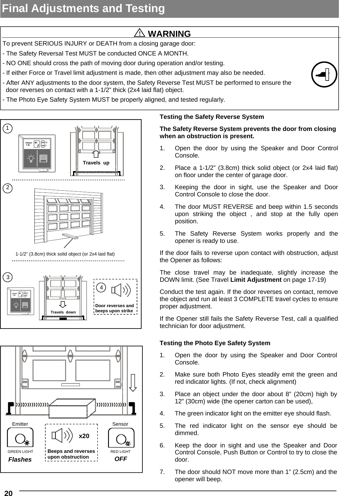
User Manual
Discussion / Help
Navigation