GUARDIAN 303RX-MBT Garage Door Opener User Manual
GUARDIAN SHANGHAI CORP. Garage Door Opener Users Manual
GUARDIAN >
Users Manual

Owner’s Manual
● Please read and understand this manual and safety instructions carefully before installation.
● The Opener WILL NOT CLOSE until the Photo Eye Safety System is properly installed and aligned.
● REGULARLY CHECK and TEST the Opener according to the safety label to ENSURE SAFE OPERATION.
● Retain this manual for future reference.
GDO Manual Revised: 03-16 GDOMU14A-1
WARNING:
To reduce the risk of injury to persons - Use this operator only with Residential Sectional Garage doors.
Serial # __ __ __ __ __ __ __ Date Installed __ __ /__ __ /__ __ __ __
Located on the bar code label on top of your opener.
The illustrations used in this instruction manual may differ from the actual product you have purchased.
2
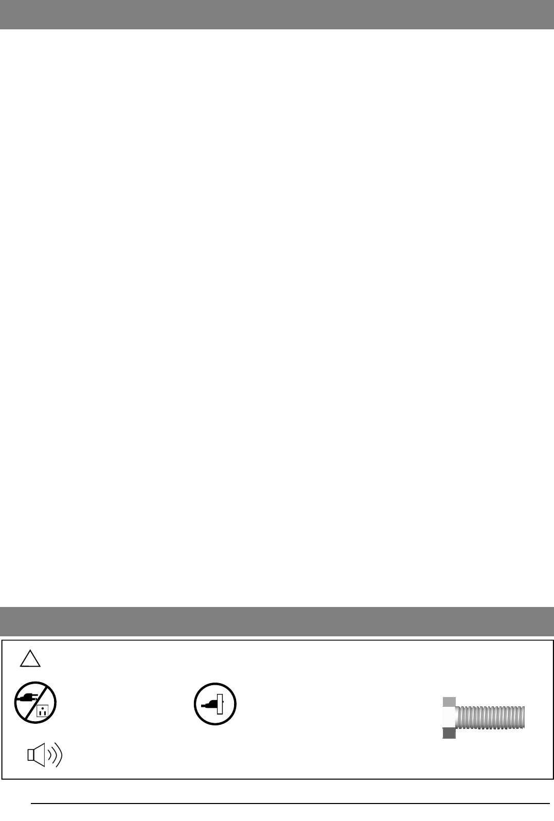
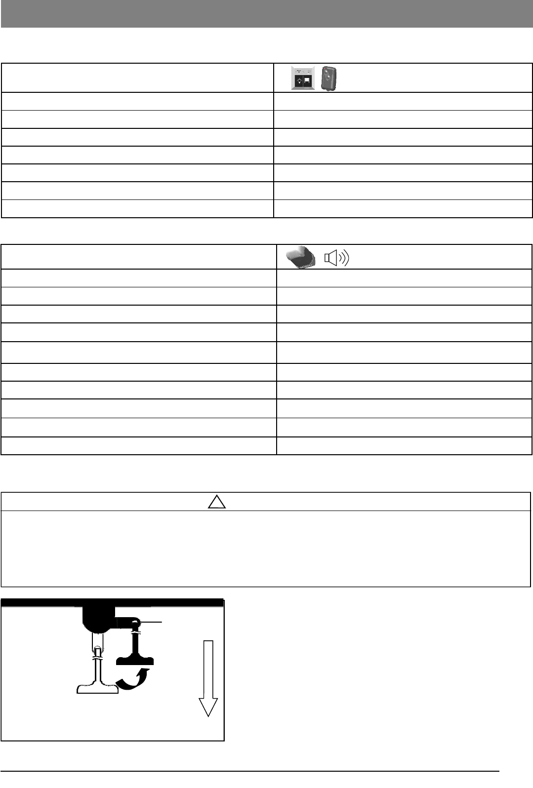
Beeps from built-in buzzer of the opener
DO NOT connect power Please connect power
Introduction
Symbols and Icons 2
Inventory 3
Preparation / Door Balance Test 4
Tools Required 4
Assembly
Assembling T-Rail 5
Tension the Belt 6
Installation
Mounting Header Bracket 7
Attaching Rail to Header Bracket and Mounting Door Bracket 8
Mounting Opener to Ceiling 9
Attaching Door Arms 10
Installing Light and Emergency Release Handle 11
Wiring
Wiring Instructions 12
Connecting Photo Eye Safety System 13
Connecting Speaker and Door Control Console 14
Bluetooth Music Playback / Hands Free Features 15
Connecting Power 16
Adjustment
Aligning the Photo Eye Safety System 16
Travel Limit Adjustment—I. UP Limit 17
Travel Limit Adjustment—II. DOWN Limit 18
Auto Force Adjustment 19
Final Adjustment and Testing 20
Operation
Programming Remote Controls 21
Operating the Opener 22-23
Maintenance 24
Troubleshooting 24
Repair Parts and Service
Installation and Accessory Parts 25
Opener Assembly parts 26
FCC Statement 27
Warranty 28
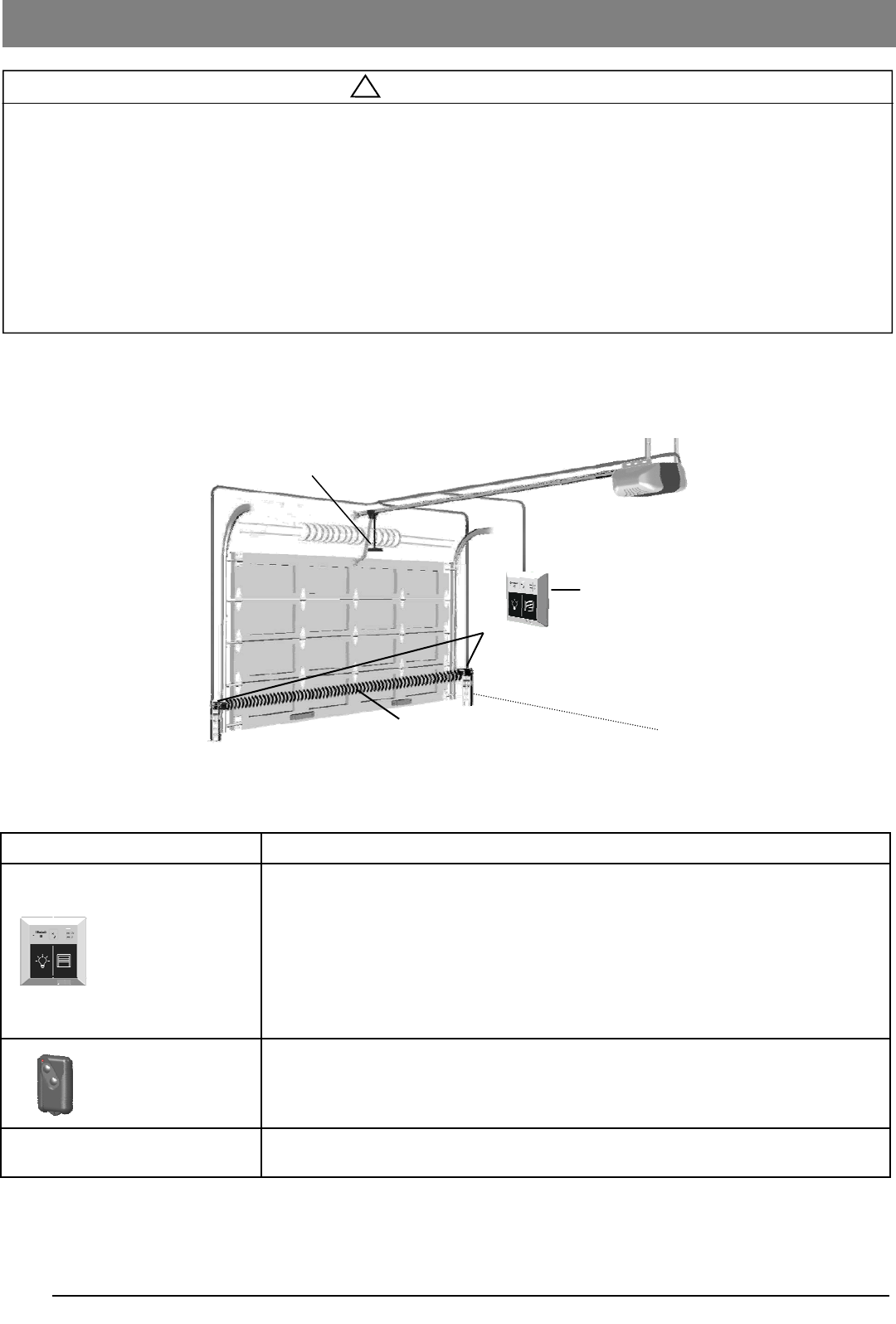
Symbols and Icons
! WARNING READ WARNINGS CAREFULLY to prevent SERIOUS INJURY or DEATH caused by
electrocution or mechanical hazard.
Installation hardware
shown in actual size
Table of Contents
3
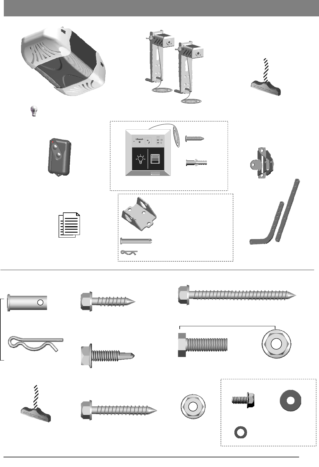
Door Bracket
Inventory
Drywall Anchor
x 2
x 2
Screw #6 x 1”
Photo Eye Safety System
Literature + Safety Labels
Door Arms
Remote Control
Header Bracket
Clevis Pin Long x1
5/16’’ x 2-1/4’’
Hitch Pin — Locking Clevis Pins x1
Emergency Release Handle
+ Rope
INSTALLATION HARDWARE, LOCATED IN HARDWARE BAG (SHOWN IN ACTUAL SIZE 1:1)
Speaker and Door Control Console
x 2
Hitch Pin
— Locking Clevis Pins
x 2
Lag Screw 5/16” x 1 5/8”
— Door Bracket
Bolt 5/16” -18 x 1” 5/16” Flange Nut
x 6 x 6
x 4
x 2
Clevis Pin — Door arms
5/16” x 1”
INSTALLATION HARDWARE, LOCATED IN HARDWARE BAG (SHOWN IN ACTUAL SIZE 1:1)
Lag Screw 5/16” x 2 1/2”
— Header Bracket
x 2
x 4
Emergency Release Handle
+ Rope
Flange Nut
1/4” -20
Sheet Metal Screw 1/4” x 1”
— Door Bracket
x 2
Lag Screw 1/4” x 1”
— Photo Eye System
Hexagonal Screw
#10 - 24 x 1/2”
Spring Washer #10
Washer #10
x 1 x 1
x 1
x 1
— Door arms / Mounting Opener
T-rail Assembly
( Light bulbs are not included)
Opener Unit + Light Lens Cover
4
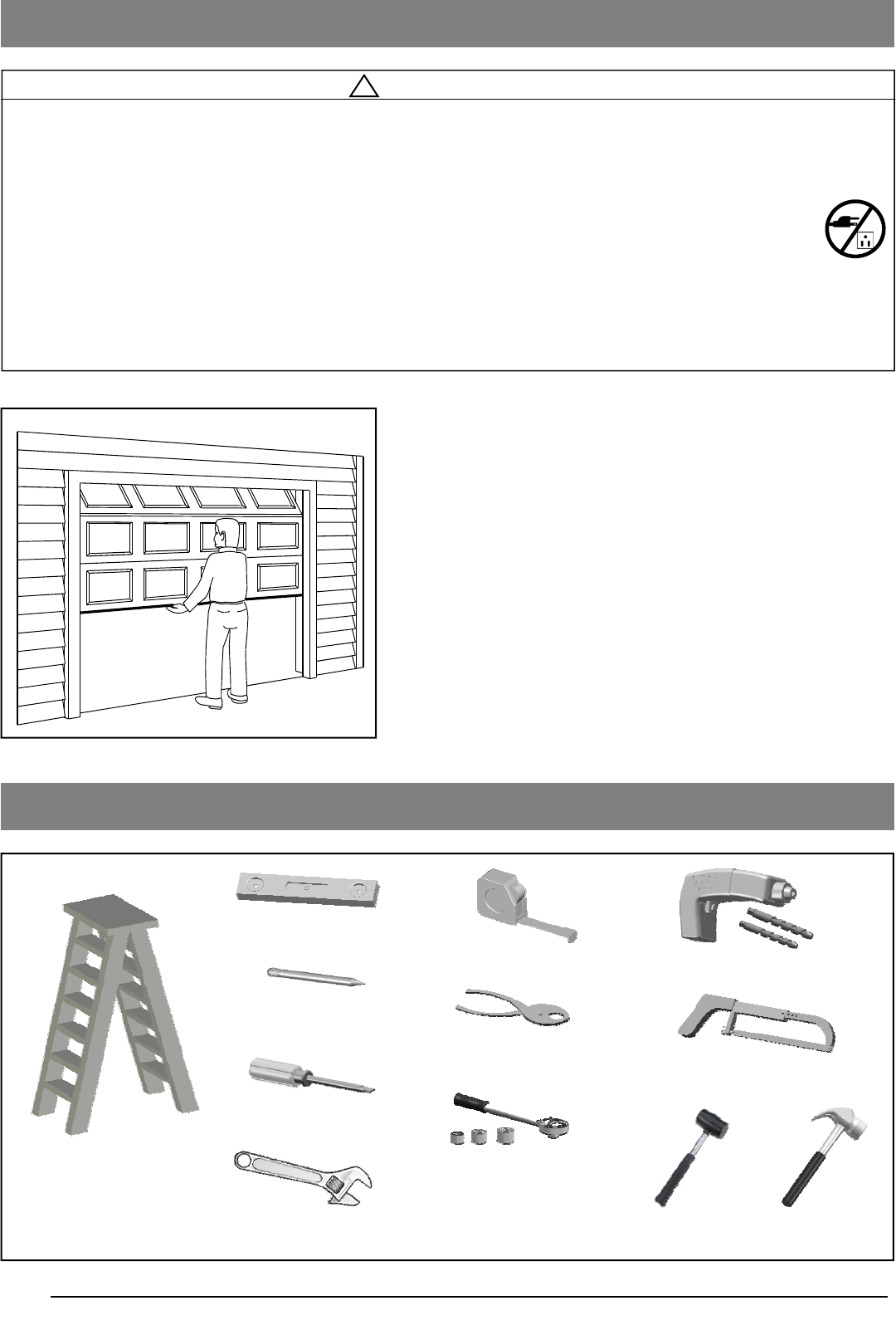
Level
Tape Measure
Hack Saw
Pencil
Drill, 3/16” and 5/16” Drill Bits
Tools Required
Step Ladder
Screwdriver
Hammer
Sectional Garage Door BEFORE Beginning Installation:
1. Disable locks and remove all ropes connected to the
garage door.
2. Perform the following door test to ensure your door is
balanced and in good working condition.
To Test Your Garage Door
1. Raise and lower the door to check if there is any sticking or
binding.
2. Check for loose hinges, damaged rollers, frayed cables and
damaged or broken springs.
3. Lift the door approximately halfway and release. The door
should stay at the point under proper spring tension.
Call a qualified garage door service technician if your door binds,
sticks or is unbalanced.
! WARNING
To prevent SERIOUS INJURY or DEATH:
- Before beginning installation of the Opener please complete the following test to ensure that your door is
balanced and in good working condition.
- A poorly balanced door can cause serious injury and damage to the Opener.
- Always have a qualified garage door service technician make any required adjustments and/or repairs to
your door before proceeding with installation.
- DISABLE ALL LOCKS and REMOVE ALL ROPES connected to the garage door BEFORE installing
and/or operating the Opener.
To prevent damage to the door and Opener:
- DO NOT connect power until instructed.
- Operate this Opener with AC 120V/60Hz power supply ONLY.
Adjustable Wrench
Ratchet with
5/16”, 7/16” and 1/2” sockets
Preparation
Pliers
Rubber Mallet
5
! CAUTION
- DO NOT connect power until instructed.
- To prevent INJURY, keep hands and fingers
away from joints and possible sharp edges.
- Wear gloves when installing chain/belt and cable.
! WARNING
To prevent SERIOUS INJURY:
- DO NOT connect power until instructed.
- Keep hands and fingers clear from sprocket during operation.
- Wear gloves when installing chain/belt and cable.
- Keep hands and fingers away from joints and possible sharp edges.
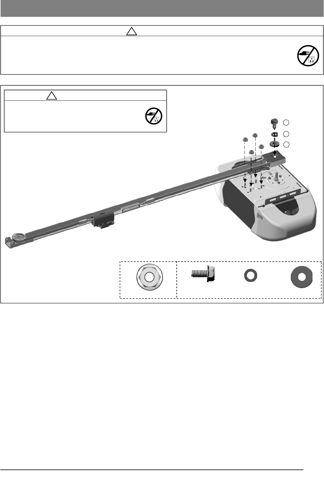
Fig.1
Assembling T-Rail
2
3
4
1/4” Flange Nut x 4
To Assemble the Rail
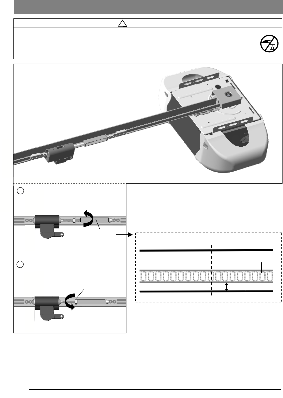
Align the pre-assembled T-rail on the top of opener in the direction as shown in Fig.1.
Secure the T-rail to the opener firmly using 1/4” flange nut x 4.
Final Step to T-Rail Installation
Fasten the Screw(2) to the motor shaft with spring washer(3) and washer(4) in between.
Hexagonal Screw
#10 - 24 x 1/2” Spring Washer #10 Washer #10
6
! WARNING
To prevent SERIOUS INJURY:
- DO NOT connect power until instructed.
- Keep hands and fingers clear from sprocket during operation.
- Wear gloves when installing chain/belt and cable.
- Keep hands and fingers away from joints and possible sharp edges.
Shaft-Linker
Tighten until...
Tighten nut
Flange Nut
2
1/4” (6mm)
Base of Rail
Mid-point of rail assembly
Belt
Top of Rail
Actual Size
1 Note: The chain or belt rail assembly comes pre-tensioned
from the factory.
Tension the Belt
1. Rotate the Shaft Linker towards the Trolley Shaft until the belt
is slightly loose about 1/4” (6mm) above the base of the rail,
referring to the actual-sized illustration below.
2. Tighten the Flange Nut on Trolley Shaft against the
Shaft-Linker.
Remove the temporary screw driver holding the position of the
trolley.
Tension the Belt / Chain
7
To Install Header Bracket
Note: Installation procedures may vary according to door
type.
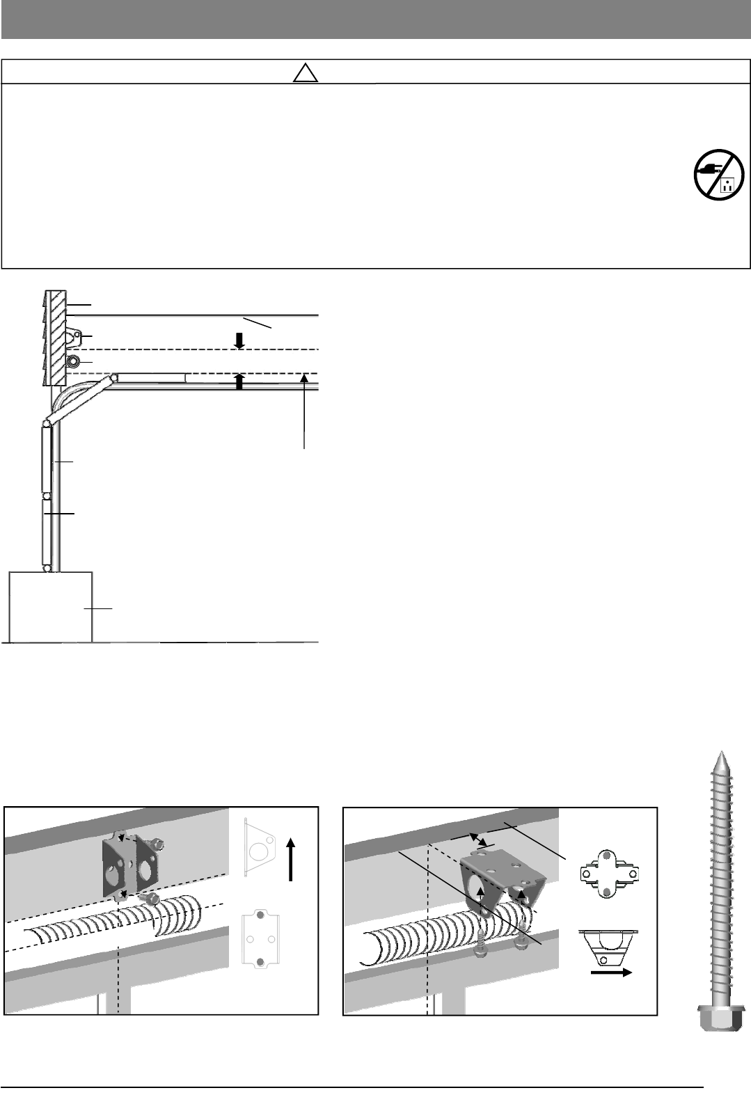
1. While inside your garage, close the door and mark the
vertical centerline of the garage door. Extend the line onto
the header wall above the door spring.
2. Open the door to the highest point of travel. Mark a line on
the header wall 2” (5cm) above the highest point of travel.
Note: DO NOT install the Header Bracket over drywall. In some
installations, it may be necessary to install a 2x4 across two wall
studs to create a suitable location for the Header Bracket.
If installing into masonry, use concrete anchors (not provided).
Wall-Mounting
As shown in Fig.2, place the Header Bracket on the vertical
centerline in direction shown.
Mark and drill two 3/16” holes. Fasten the Header Bracket
securely to a structural support using two 5/16” x 2-1/2” Lag
Screws.
Alternative Ceiling-Mounting
Ceiling-mounting is suggested ONLY when clearance is minimal.
Extend the vertical centerline onto the ceiling as shown in Fig.3.
Center the Header Bracket on the vertical mark, no more than
6” (15cm) from the header wall. Mark and drill holes to fasten the
Header Bracket securely to a structural support.
Fig.1
Ceiling
Header Bracket
Header Wall
2” (5cm) clearance
Door Track
Door
Highest Point of Door Travel
Support block on floor
Door Spring
! WARNING
To prevent SERIOUS INJURY:
- DO NOT connect power until instructed.
- The Header Bracket MUST be SECURELY fastened to the structural support on the mounting wall or
ceiling, otherwise the door may not reverse when required. DO NOT install the Header Bracket over drywall.
- Concrete anchors MUST be used when mounting the Header Bracket into masonry.
- NEVER try to loosen, move or adjust garage door springs, cables, Pulleys, Brackets, or hardware, all of
which are under EXTREME tension.
- Contact a qualified garage door service technician if your door binds, sticks or is unbalanced. An unbalanced
door might not reverse when required.
Mounting Header Bracket
UP
OPENER
MAX. 6” (15cm)
Highest Point of Door Travel
Vertical Centerline
Horizontal Line
Finished Ceiling
Lag Screw
5/16” x 2-1/2”
Vertical Centerline
Fig.2 (Wall-Mounting) Fig.3 (Ceiling-Mounting)
8
! CAUTION
To prevent SERIOUS INJURY:
- DO NOT connect power until instructed.
- REINFORCEMENT is recommended for fiberglass, aluminum or lightweight steel garage doors BEFORE
installing the door Bracket. Contact your door manufacturer for reinforcement options.
Fig.1
Fig.3
(a) (b) (c)
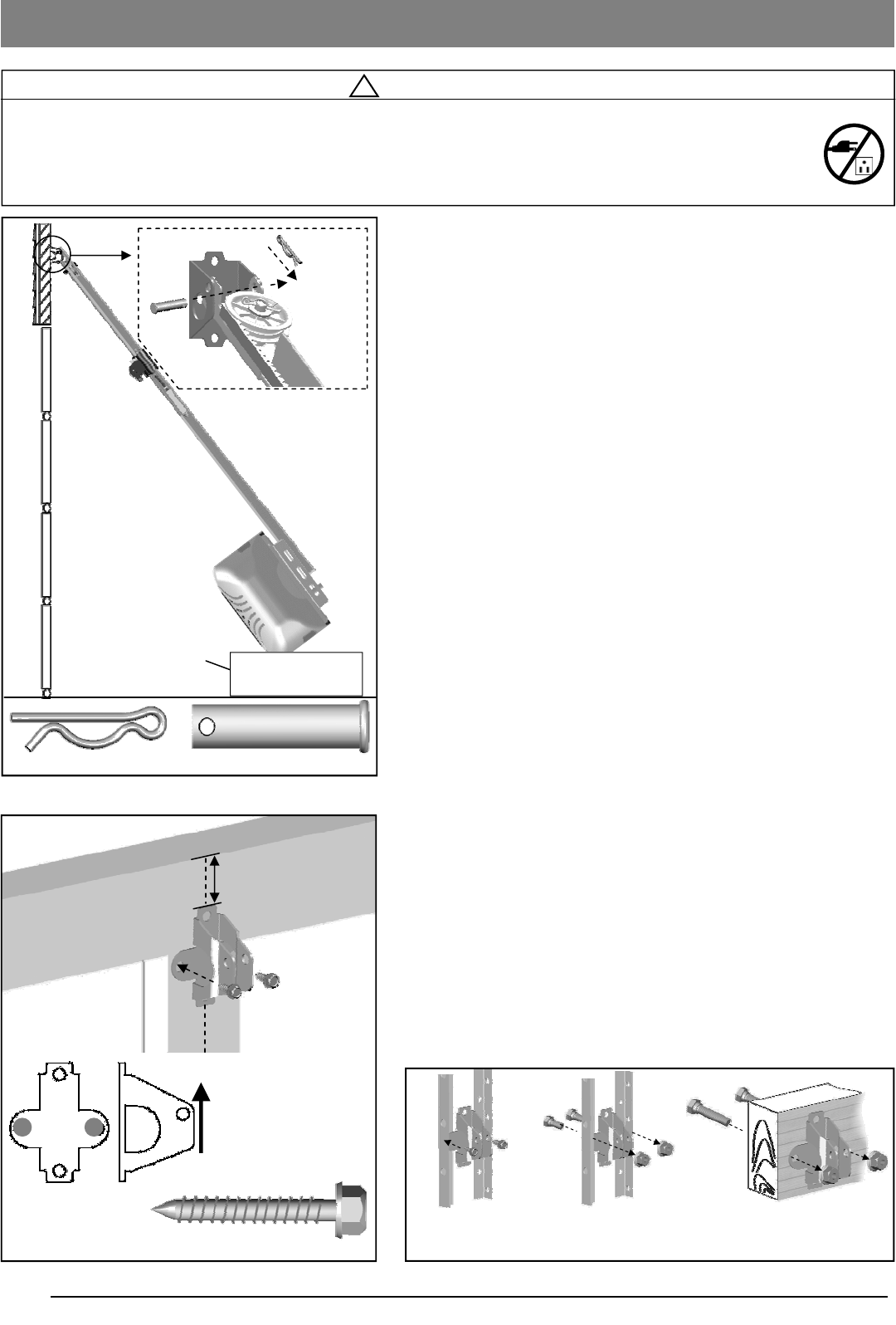
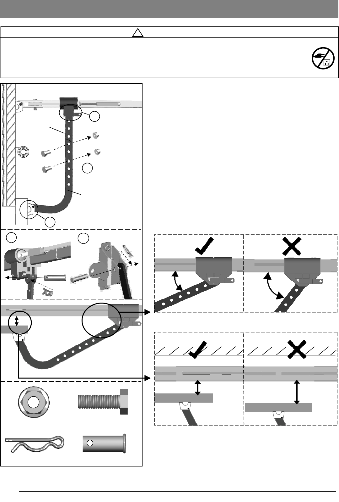
To Attach the Opener to the Header Bracket
1. As shown in Fig.1, use the packaging carton as temporary
support for the Opener. Place the Opener on carton to
prevent damage.
2. Align the mounting hole on the header rail to the mounting
hole on the Header Bracket.
3. Connect the Header Rail and the Door Bracket together with
a 5/16” x 2-1/4” Clevis Pin and lock it in place with a Hitch
Pin.
To mount the Door Bracket
Note: Some door reinforcement kits may provide direct
attachment of the door arm to the reinforcement bracket. If you
have a door reinforcement bracket with this option, skip this step
and proceed with the next step “Mounting Opener to Ceiling”.
1. Position the Door Bracket on the centerline of the door
approximately 2” - 4” (5-10cm) below the top edge of the
door. Secure the Door Bracket with 5/16” x 1 5/8” Lag Screw
(provided) as shown in Fig.2.
2. Alternately, depending on the construction of your door,
install using one of the steps shown if Fig. 3 below:
For steel / lightweight doors with vertical steel
reinforcements / factory reinforced.
(a) Mark and drill two 3/16” holes. Make sure not to drill
through the garage door. Secure the Door Bracket with two
1/4” x 1” Sheet Metal Screws (provided) as shown in Fig.3
(a).
(b) Alternative installation: Drill two 5/16” holes through the
door. Secure the Door Bracket using two 5/16” carriage
Bolts, lock washers and nuts (not provided) as shown in
Fig.3(b). The length of bolts will depend on the thickness of
your door.
Wood door
(c) Mark and drill two 5/16” holes through the garage door.
Secure the Door Bracket using two 5/16” carriage bolts,
washers and nuts (not provided) as shown in Fig.3(c). The
length of bolts will depend on the thickness of your door.
Note: DO NOT use Sheet Metal Screws on a wood door.
Attaching Rail to Header Bracket and Mounting Door Bracket
Fig.2
UP
Vertical Centerline of Door
2-4” (5-10cm)
Top Edge of Door
Carton
Clevis Pin - 5/16” x 2-1/4”
Hitch Pin
Lag Screw 5/16” x 1 5/8” Sheet Metal Screw
1/4” x 1”
Not Provided Not Provided
9
! WARNING
To prevent SERIOUS INJURY or DEATH:
- DO NOT connect power until instructed.
- Install the Opener at least 7 feet (2.13m) above the floor.
- Fasten the Opener SECURELY to STRUCTURAL SUPPORTS of the garage to prevent falling.
- If installing Brackets to masonry, concrete anchors (not provided) MUST be used.
Mounting Opener to Ceiling
Angle Iron not provided
Fig.1
Fig.2
Fig.3
Structural support
Finished ceiling
Bolt / Lock
Washer / Nut
Bolt / Lock
Washer / Nut
Angle Iron not provided
Finished ceiling
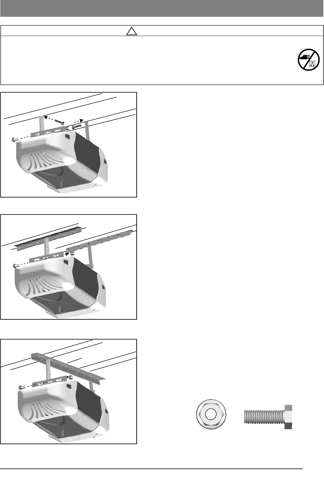
To Mount the Opener to Ceiling
The three most common installation options are shown in
Fig.1-3.
Fig.1 shows mounting the Opener directly to structural
support on the ceiling. Fig.2 and 3 show mounting on a
finished ceiling, with heavy duty angle iron*.
*angle iron not included
Determine the mounting option that works best for your
application and follow installation steps below:
1. Raise the Opener and rail assembly and temporarily place it
on a stepladder.
2. Position the Opener and rail assembly so that it is aligned to
the center line of the garage door. If the Header Bracket
was mounted off center, align the Opener with the Header
Bracket.
3. Measure the distance from each side of the Opener to the
structural supports.
4. Cut both Hanging Brackets* to appropriate length
*(Hanging Bracket not included)
5. Drill 3/16” holes in the structural supports.
6. Secure one end of each of the Hanging Brackets to the
structural supports using 5/16”x2-1/2” Lag Screws (not
provided).
7. Secure the Opener to the Hanging Brackets and secure
each side with a 5/16”-18x1” Bolt and 5/16” Flange Nut
(provided).
8. Move the door manually to check clearance between
highest point of travel of the door and rail. If the door hits the
rail, raise the Header Bracket or adjust the mounting of
Opener.
9. Remove the ladder ONLY when the Opener is securely
mounted to the structural supports.
Bolt 5/16” - 18 x 1”
5/16” Flange Nut
Securing Opener to Hanging Brackets
10
! WARNING
To prevent SERIOUS INJURY:
- DO NOT connect power until instructed.
- Keep hands and fingers away from the sprocket during operation.
- Wear gloves when installing chain/belt and cable.
- Keep hands and fingers away from joints and possible sharp edges.
Attaching Door Arms
Clevis Pin - 5/16” x 1”
Hitch Pin
Bolt 5/16” - 18x1”
Flange Nut
1 2
Fig.1
To Connect Door Arm
Follow the steps shown in Fig. 1
1. Fasten the Straight Door Arm to the Trolley with a
5/16” x 1” Clevis Pin and lock it with a Hitch Pin.
2. Fasten the Curved Door Arm to the Door Bracket with
5/16” x 1”Clevis Pin and lock it with a Hitch Pin.
3. To connect the door arms together, choose two pairs of holes
which are as far apart as possible. Fasten the arms using two
5/16” x 1” Bolts and Flange Nuts.
<1-3/4”mm
>1-3/4”mm
Ceiling Ceiling
Rail of Opener
Door Panel
Rail of Opener
Door Panel
Curved Door Arm
Straight Door Arm
1
2
3
NOTE: The straight door arm must be installed vertically to
the door when door is at closed position.
11
! WARNING
To prevent SERIOUS INJURY or DEATH from electrocution:
- Disconnect power cord before installing/replacing light bulb.
To prevent possible OVERHEATING or damage to Opener:
- Use ONLY A19 (E26) incandescent bulbs (100W max.).
- DO NOT use short neck or specialty light bulbs.
- DO NOT use halogen bulbs.
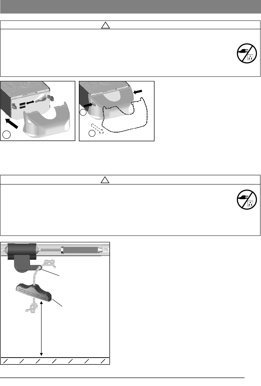
Safety Notice
Mount the emergency release within reach, but at least 6 feet
above the floor and avoiding contact with vehicles to avoid
accidental release.
To attach the Emergency Release Handle:
1. Thread one end of the rope through the hole of the
Emergency Release Handle and secure with an overhand
knot.
2. Thread the other end of the rope through the hole in the
Trolley lever.
3. Measure the rope length so that the handle is 6 feet
(183cm) above the floor and is clear from the top of your
vehicle. Secure with a overhand knot.
Fig. 2
! WARNING
To prevent SERIOUS INJURY or DEATH from a falling garage door:
- In case of power failure or door obstruction, PULL EMERGENCY HANDLE to release door from Opener.
- When Emergency Release is in the released position, the door can be operated manually.
- To reconnect, flip the lever on the Trolley towards Opener, back to Connect position, it will reconnect auto-
matically upon pressing the Door Control Button on the Speaker and Door Control Console or Remote Con-
trol.
- DO NOT use Emergency handle to pull the door open or closed.
Installing Light and Emergency Release Handle
6 feet (1.83m) above floor
Lever
Emergency Release Handle
Fig. 2
To install light bulb as shown in Fig.1:
1. Install a standard A19 (E26) 100 watt
maximum light bulb.
2. Re-attach the Light Lens Cover
To replace light bulb as shown in Fig.2:
1. Press the release buttons and detach it
from the Opener.
2. Replace light bulb and reattach the
Light Lens Cover.
Notice
When replacing the light bulb, make sure the
bulb on the Opener has cooled down to pre-
vent injury.
1
2
Fig.1
2
100W MAX
12
In the following section, the Photo Eye Safety System and
Door Control Console will be connected to the Opener.
Please read and understand the wiring instructions before
connecting wires.
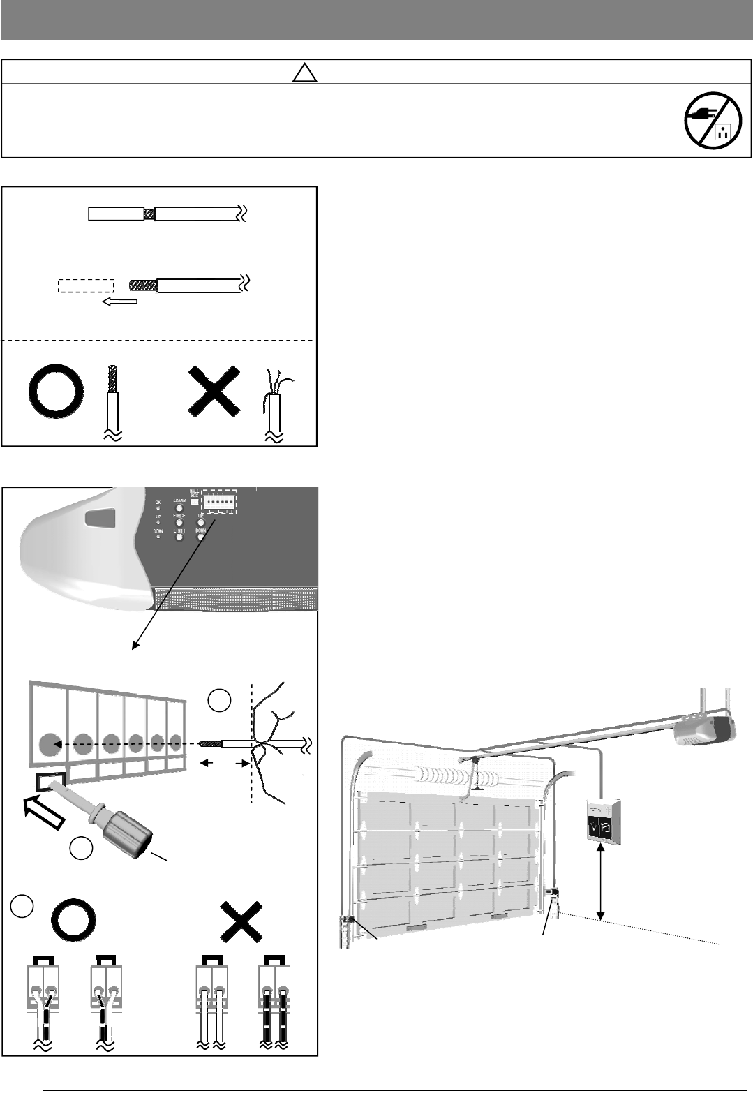
1. Remove the pre-cut skin on the open end of wire from
accessories. Wires MUST NOT be frayed and connected
properly as shown in Fig.1.
2. To connect a wire to an assigned terminal, use a small “flat
head” screwdriver to push in the orange tab on the Wire
Terminal as shown in Fig.2.
3. Insert approximately 1/2” (13mm) of the wire into the
terminal while pushing in the tab as shown in Fig.2.
4. Each accessory requires a pair of terminals, Each pair of
terminals MUST be connected with one white wire and one
striped wire (non-polarized) from the SAME accessory as
shown in Fig.2.
5. Check for proper connection by gently pulling on the wire.
The wire should not come out of the terminal. NO exposed
part of the wire should be visible outside of the terminal.
6. Use the insulated staples provided to secure the wires to
the wall and/or ceiling. Be careful not to damage the wires
while securing the staples.
! WARNING
To prevent SERIOUS INJURY or DEATH from electrocution:
- Power MUST NOT be connected until instructed.
- NO exposed part of the wire should be visible outside of the terminal for proper connection.
Min. 5 feet (1.5m)
above floor
Wiring Instructions
Photo Eye Safety System
Fig. 2
Wire shown in actual size
1/2”
Wire Terminals
Fig. 1
2
3
Screwdriver or similar tool
1
Wire from accessories
Remove and discard pre-cut skin
PUSH BUTTON
PHOTO EYE
PUSH BUTTON
PHOTO EYE
Speaker and Door
Control Console
13
! WARNING
To prevent SERIOUS INJURY or DEATH from electrocution:
- Power MUST NOT be connected BEFORE Photo Eye Safety system is connected and aligned.
- The Opener will not operate until the Photo Eye Safety System is properly connected and aligned.
- Install the Photo Eyes NO higher than 6” (15cm) above the floor.
No part of garage door or other objects should obstruct the Photo Eye Safety System during door-closing.
Connecting Photo Eye Safety System
About the Photo Eye Safety System
The Photo Eye Safety System provides protection against
entrapment while the door is closing. When properly connected
and aligned, the emitter Photo Eye emits an invisible infrared
light beam while the Sensor Photo Eye monitors that beam.
If the beam is obstructed during door-closing, the entrapment
protection will be triggered and the door will stop and reverse to
the open position. The opener will beep for 20 times indicating
an obstruction.
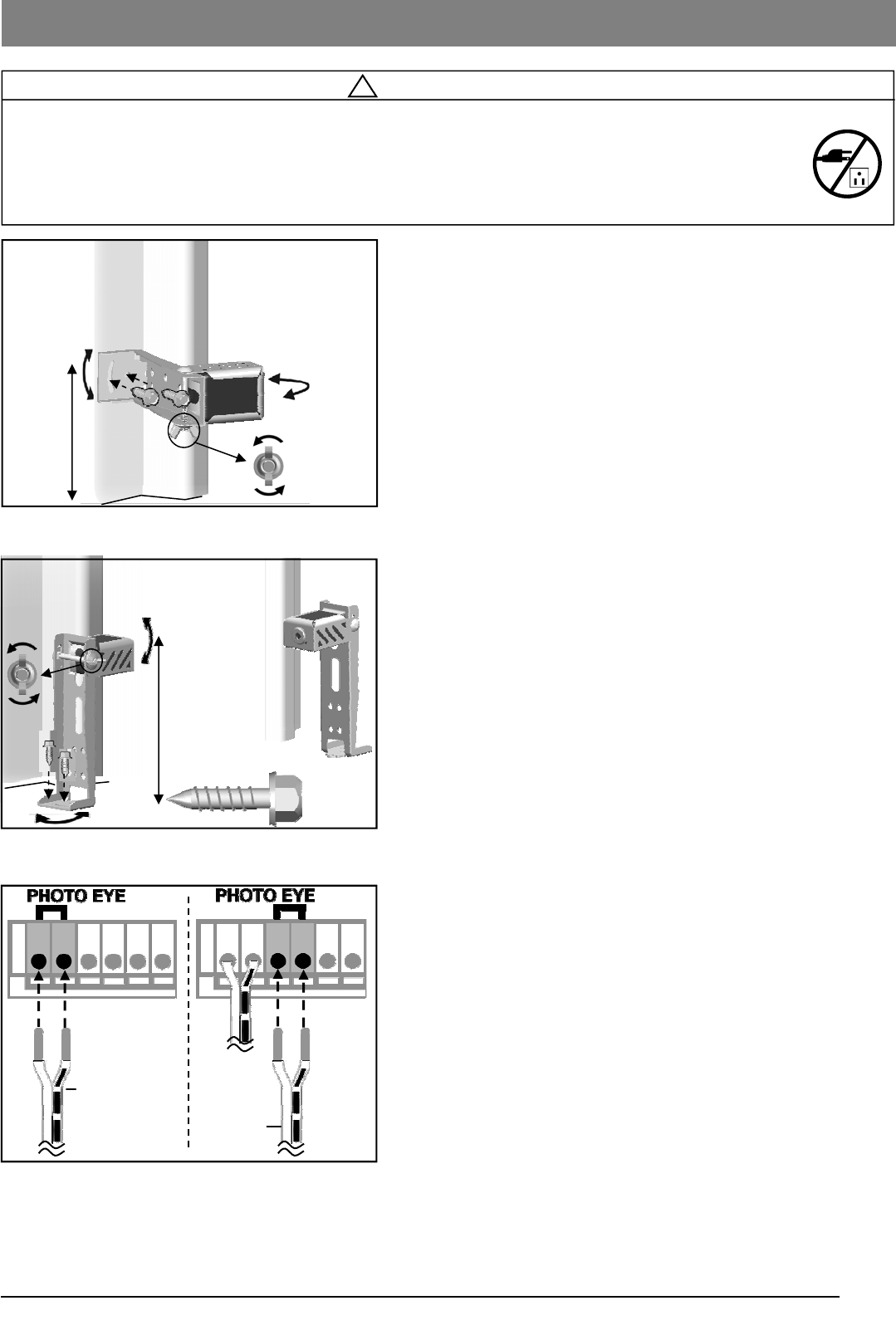
Installing The Photo Eye Safety System
Wall-mounting
1. Place the Photo Eyes facing each other on each side of
the garage door. Position the sensors so they are no
higher than 6” (15cm) above the floor, as shown in Fig.1.
2. Drill 3/16” holes using the mounting holes on the Bracket
as a template. Secure with #12 x 1” Lag Screws
(provided).
3. If necessary use the Optional Wall-mount Position (Fig.1)
to better fit your door-track and improve obstacle
avoidance. To adjust the position, loosen the wing nut,
disassemble the Bracket and move the Photo Eye to the
lower position on the holder.
4. If necessary, align the Photo Eyes by loosening the wing
nut . (This step may be further required in Aligning the
Photo Eye Safety System on page 16.)
Alternative Floor-mounting
1. Place the Photo Eyes facing each other on each side of
the garage door, as shown in Fig.2.
2. If attaching to concrete, secure the photo eyes using
concrete anchors and bolts (not provided).
3. If necessary, align the Photo Eyes by loosening the wing
nut. (This step may be further required in Aligning the
Photo Eye Safety System on page 16.)
To Connect Photo Eye Safety System
1. Connect a pair of wires from either one of the Photo Eyes
to a pair of “PHOTO EYE” terminals on the rear of the
Opener as shown in Fig. 3. Refer to Wiring Instructions
on page 12 for proper connections.
2. Repeat above step to connect the other Photo Eye.
3. Refer to Wiring Instructions on page 12 to ensure wires
are connected properly.
Fig. 2 (Floor Mount)
Fig. 3
From one of
the Photo Eye From the
other one
Fig. 1 (Wall Mount)
#12 x 1”
Lag Screw
Loosen
Inside
Garage
Door Track
6” max. above floor
Alignment
Alignment
Inside
Garage
Door Track
6” max.
Inside
Garage
14
! WARNING
To prevent SERIOUS INJURY or DEATH from electrocution:
- Power MUST NOT be connected until instructed.
To prevent SERIOUS INJURY or DEATH from using the Speaker and Door Control Console or Push Button
and a closing door:
- Install the Speaker and Door Control Console or Push Button within sight of the door at a minimum height
of 5 feet (1.5m) above the floor. Make sure it is out of the reach of children and moving parts of door
and hardware.
- NEVER permit children to access the Speaker and Door Control Console, Push Button or Remote Controls.
- Operate the door ONLY when it is adjusted properly with no obstructions present and is in clear sight.
- ALWAYS keep a moving door in sight until it’s completely closed.
- NEVER cross the path of a moving door.
Drywall Anchor
Screw #6 x1”
Min. 5 feet (1.5m)
above floor
Fig. 1
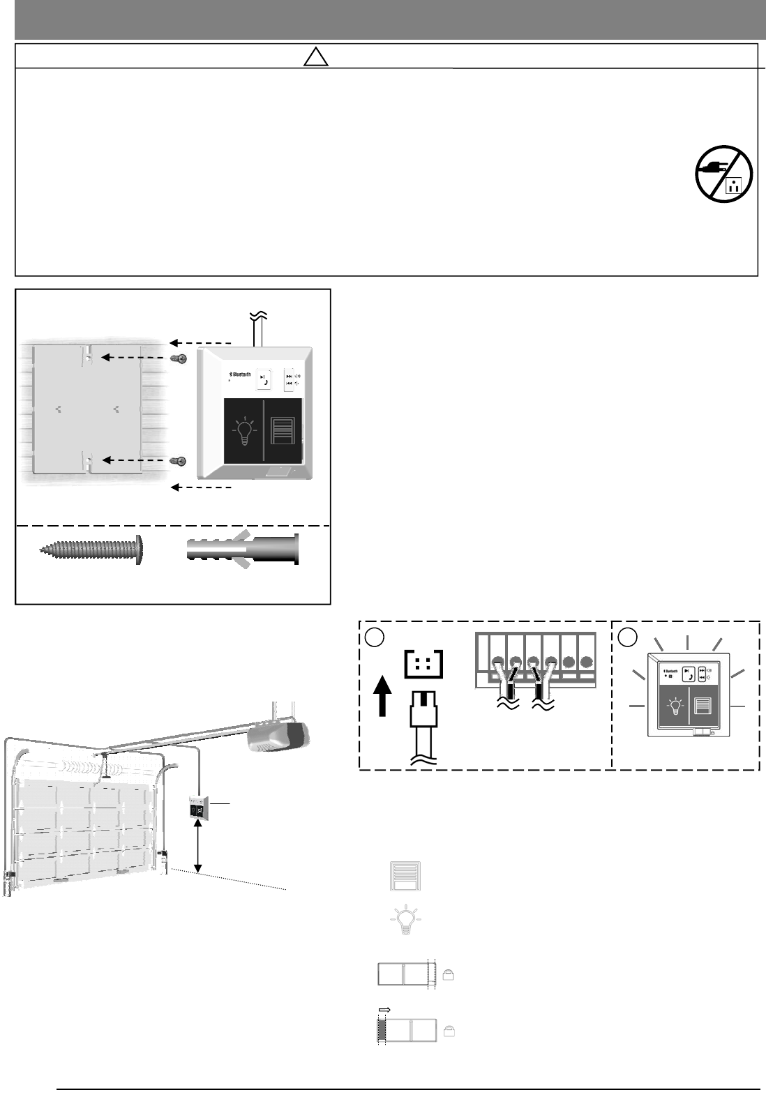
Connecting Speaker and Door Control Console
The Speaker and Door Control Console is a wired, illuminated
door and Bluetooth device control with speakers
To install the Speaker and Door Control Console:
1. Inside your garage, install the back plate of the Speaker
and Door Control Console within sight of the door at a
minimum height of 5 feet (1.5m) off the ground. Ensure it is
installed out of the reach of children and free from the
moving parts of the door and hardware.
2. Fasten it to a solid surface with 1” screws. If attaching to
drywall or other hollow surface, drill 3/16” holes and use
the provided Drywall Anchors.
3. Snap the Speaker and Door Control Console onto the
back plate.
To Connect the Speaker and Door Control Console
Connect the plug from the Speaker and Door Control Console
to the “Wall Panel” outlet on the rear of the Opener, as shown in
Fig.2.
Fig. 2
UNLOCK
Speaker and Door Control Console
(ONLY after installation is completed )
Door — Press and release to access the door
Light — Turns the courtesy light On/Off
Wall
Panel
1 2
Check illumination after
connecting power
Speaker and Door
Control Console
LOCK
Vacation Lock
Unlock — Door can be accessed by either Door
button or controls
Lock — Prevent access of door by any controls
and Door button.
From Speaker and
Door Control Console
15
Trouble-shooting
Unit doesn't respond
- If the unit appears to be “frozen” or locked up, you may need
to reset it. To do so, unplug the power of GDO and re-plug.
- Once reset, you will need to adjust them and re-pair with your
Bluetooth devices.
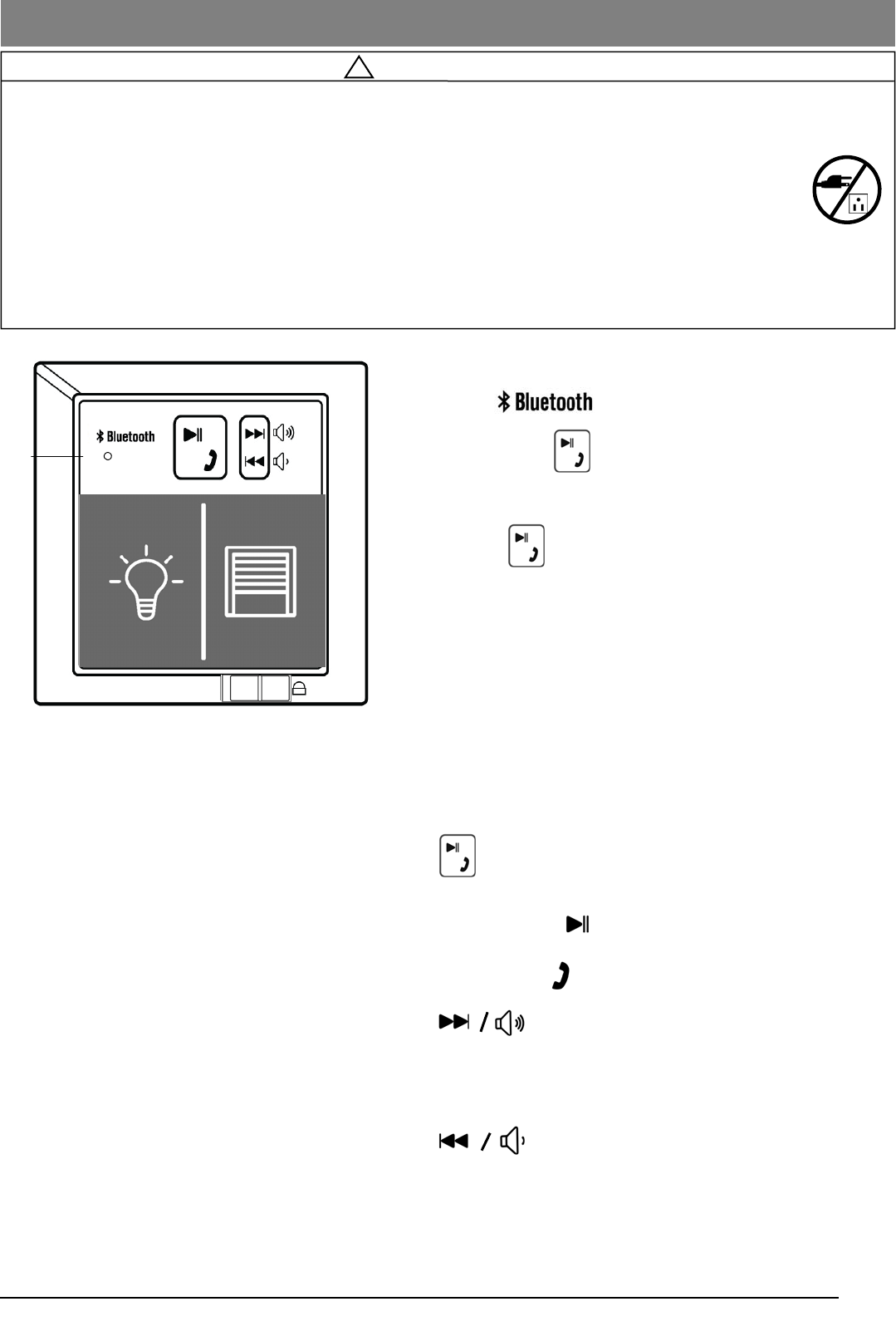
Music Playback Controls
Play/Pause / Phone
- Music Playback
- Speakerphone
-
Momentary press - Next song
Constant press - Volume up
-
Momentary press - Previous song
Constant press - Volume down
! WARNING
To prevent SERIOUS INJURY or DEATH from electrocution:
- Power MUST NOT be connected until instructed.
To prevent SERIOUS INJURY or DEATH from using the Speaker and Door Control Console or Push Button
and a closing door:
- Install the Speaker and Door Control Console or Push Button within sight of the door at a minimum
height of 5 feet (1.5m) above the floor. Make sure it is out of the reach of children and moving parts of
door and hardware.
- NEVER permit children to access the Speaker and Door Control Console , Push Button or Remote Controls.
- Operate the door ONLY when it is adjusted properly with no obstructions present and is in clear sight.
- ALWAYS keep a moving door in sight until it’s completely closed.
- NEVER cross the path of a moving door.
Bluetooth Music Playback / Hands free Features
Pairing using Bluetooth:
1. Enable on handheld device
2. Press and hold button on the wall control until it flashes
2. Search and choose "GUARDIAN" on handheld device
3. Flashing indicator on wall console will glow steadily as
confirmation and your music will be played through the
opener speakers.
MIC
16
! WARNING
To prevent SERIOUS INJURY or DEATH from electrocution or fire:
- Power MUST be DISCONNECTED BEFORE proceeding with permanent wiring procedures.
- Garage Door Opener installation and wiring MUST be in compliance with all local electrical and building
codes. Make sure the Opener is ALWAYS grounded.
- NEVER use an extension cord, 2-wire adapter or modify the power plug in any way to make it fit the outlet.
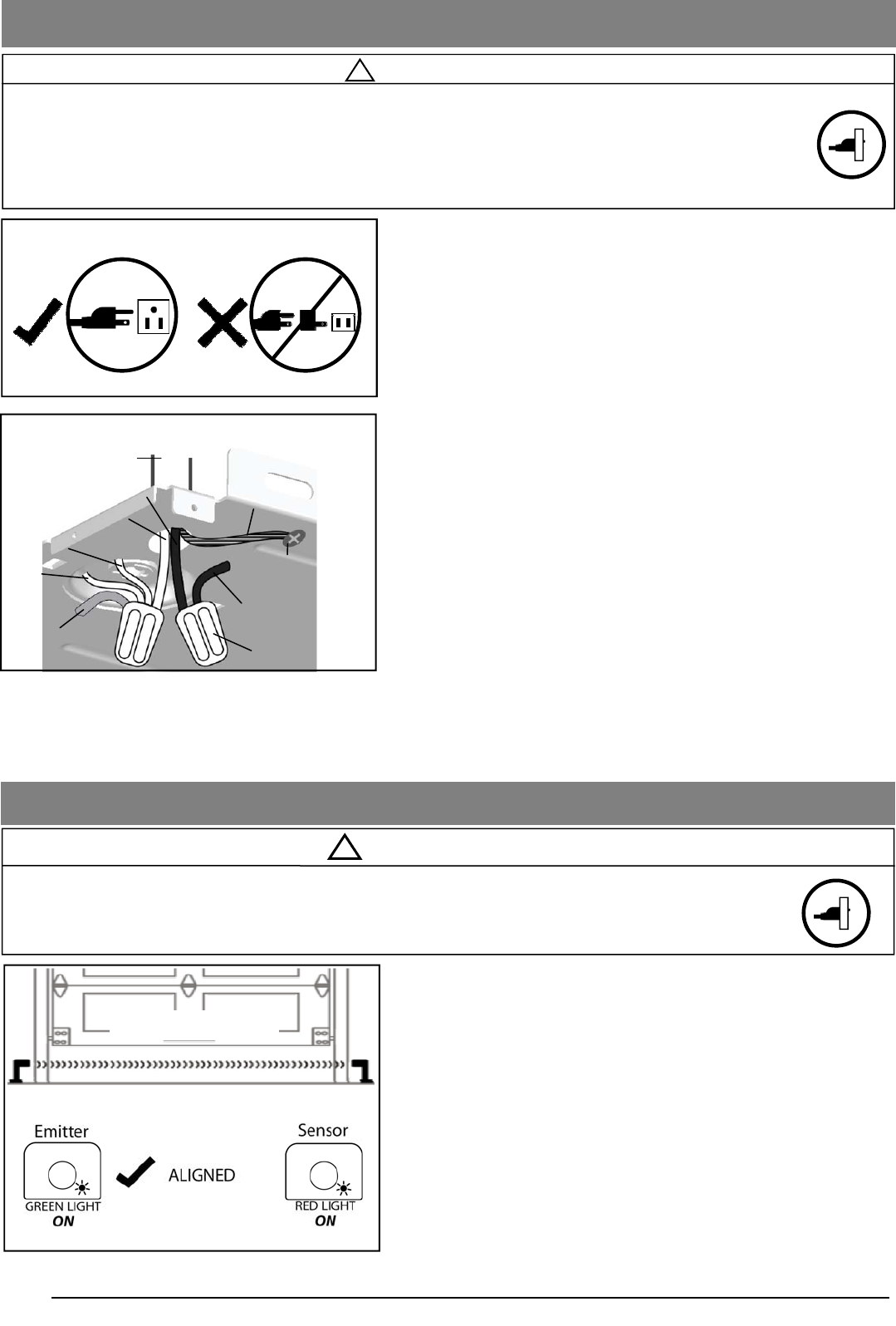
Connecting Power
To Align the Photo Eye Safety System:
1. When the Photo Eye System is properly connected and the
power is connected, one of the Photo Eyes will emit a
steady green light. This Photo Eye is the Emitter that
generates the Invisible Light Beam.
2. When properly aligned, the Sensor should emit a steady
red light when it senses the invisible light beam from the
Emitter.
3. If the indication is unsteady, flashes or is dim, check for
any obstructions and adjust the position until the Sensor
gives a STEADY RED LIGHT.
Note: The path of the invisible light beam MUST NOT be
obstructed. No part of the garage door or any
hardware should interfere with the beam or the
Opener will not close the door.
Aligning the Photo Eye Safety System
To prevent SERIOUS INJURY or DEATH from a closing garage door:
- The Photo Eye Safety System MUST be installed BEFORE connecting power.
- The Photo Eye Safety System MUST be properly connected and aligned BEFORE operating the Opener.
! WARNING
Invisible Light Beam
Ordinary Power Connection
For Permanent Wiring ONLY
Conduit with wire
Yellow (from Motor)
White (from Light)
Neutral (White)
Wire nut (Not provided)
White
(from Logic Board)
Line (Black ) Ground (Green/Yellow)
Black (from Logic Board)
Ground Screw (Green)
DO NOT OPERATE OPENER AT THIS TIME.
To Connect Power
Plug the Opener into a grounded outlet ONLY. If there is no
grounded outlet present, call a qualified electrician to replace the
outlet. Use of a surge protector is highly recommended.
Permanent Wiring (If Required by Local Code)
1. Remove the enclosure by removing the 6 screws located
on the sides and rear of the Opener.
2. Cut the two cable pressure connectors connecting line
(black) and neutral (white) wire from the power cord.
3. Remove the grounding screw connecting the green wire.
4. Remove the power cord.
5. Group neutral (white) wires from power source with 2 white
wires from light cable, and logic board, and yellow wire
from motor, inside the Opener. Connect them with a wire
nut.
6. Group line (black) wires from power source with another
black wires from logic board inside the Opener. Connect
them with a wire nut.
7. Secure the ground (green or bare) wire from the power
source with a grounding screw.
8. Reinstall the enclosure.
9. Turn on power supply. If the wiring is properly connected, a
“click” should be heard and the light will illuminate (if a bulb
is installed). If there is no response from the Opener, check
power source and wiring.
17
! WARNING
To prevent SERIOUS INJURY or DEATH from improper Force Adjustment:
- DO NOT adjust force to compensate for binding or sticking of the garage door. Call a qualified garage door
service person to make necessary adjustments in case of binding.
- DO NOT increase force beyond minimum force required for closing the door. Too much force will cause
improper operation of safety reversal mechanism.
- After ANY adjustments, Safety Reverse Test MUST be performed to ensure the door reverses on con-
tact with a 1.5” high object (2x4 laid flat).
Travel Limit Adjustment— I. UP Limit
x1
UP
DOWN
FORCE
LIMIT
UP
DOWN
UP
DOWN
FORCE
LIMIT
UP
DOWN
Desired UP limit
Flashes and off
I. Setting UP Limit
UP
DOWN
FORCE
LIMIT
UP
DOWN
OK
1
2
3
4
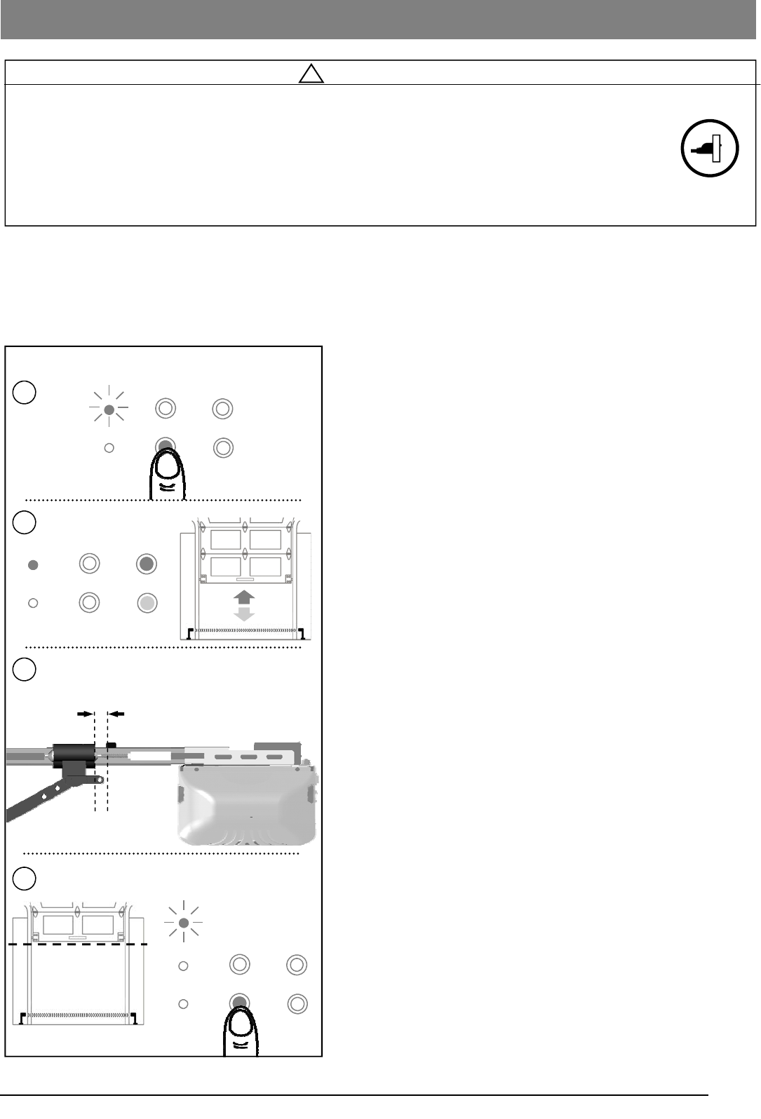
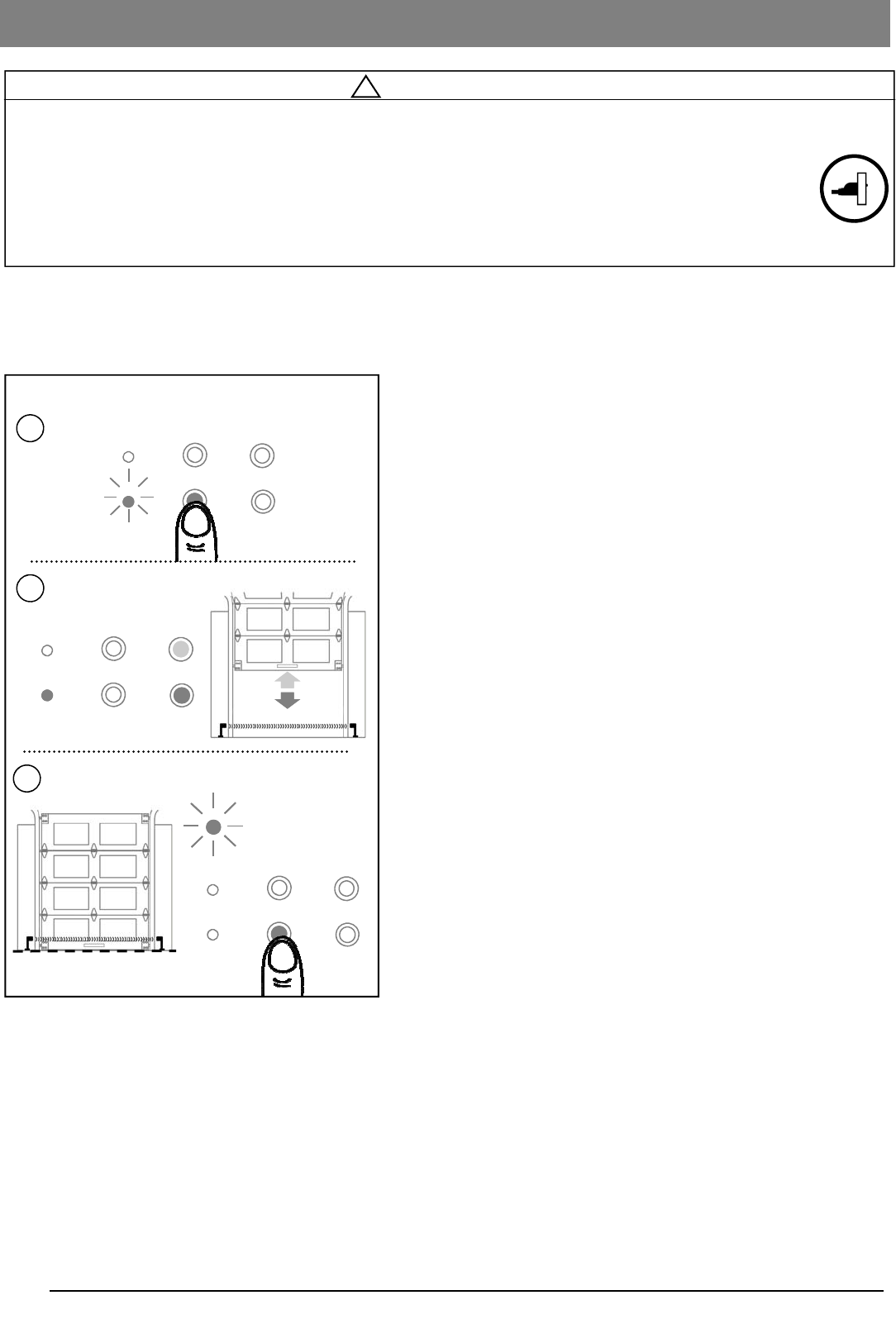
About Travel Limit Adjustment
Limit Adjustments regulate the fully-open (UP limit) position and
fully-closed (DOWN limit) position at which the door will stop
when opening and closing.
Make sure the trolley is engaged before proceeding
adjustments.
I. Setting UP Limit
1. Press “LIMIT” button once to enter Travel Limit
Adjustment. “UP” indicator (green) is on*.
*NOTE: Once you have pressed and released the “Limit”
button, the “UP” light will stay for 10 seconds for you to
press the “UP” button and begin programming. If the “UP”
light goes out before you are finished you need to start
over.
2. Press & hold the “UP” button, the door travels up. You may
use both “UP” or “DOWN” buttons to inch-adjust the door
to the desired UP limit position.
3. Make sure there is enough clearance for your vehicle(s),
and there is a minimum 2“ (5cm) gap between Trolley and
Stop Bolt.
4. Once the door is at the desired UP limit position, press
“LIMIT” button once, “OK” indicator (orange) flashes and
goes off. The UP limit is set.
NOTICE: This opener will not work until you set the travel limits and the travel force
adjustment. The opener will beep 5 times if it is operated without program-
ming.
Stop Bolt
Trolley
Minimum 2” (5cm) clearance
18
! WARNING
To prevent SERIOUS INJURY or DEATH from improper Force Adjustment:
- DO NOT adjust force to compensate binding or sticking of the garage door. Call a qualified garage door
service person to make necessary adjustments in case of binding.
- DO NOT increase force beyond minimum force required for closing the door. Too much force will cause
improper operation of safety reversal mechanism.
- After ANY adjustments, Safety Reverse Test MUST be performed to ensure the door reverses on contact
with a 1.5” high object (2x4 laid flat).
Travel Limit Adjustment— II. DOWN Limit
Desired DOWN limit
Flashes and off
II. Setting DOWN Limit
UP
DOWN
FORCE
LIMIT
UP
DOWN
UP
DOWN
FORCE
LIMIT
UP
DOWN
OK
x2
UP
DOWN
FORCE
LIMIT
UP
DOWN
x1
1
2
3
CAUTION: WHILE SETTING THE DOWN LIMIT, CAREFULLY
WATCH DOOR TRAVEL DISTANCE. RELEASE BUTTON
WHEN THE DOOR MAKES CONTACT WITH THE GROUND!
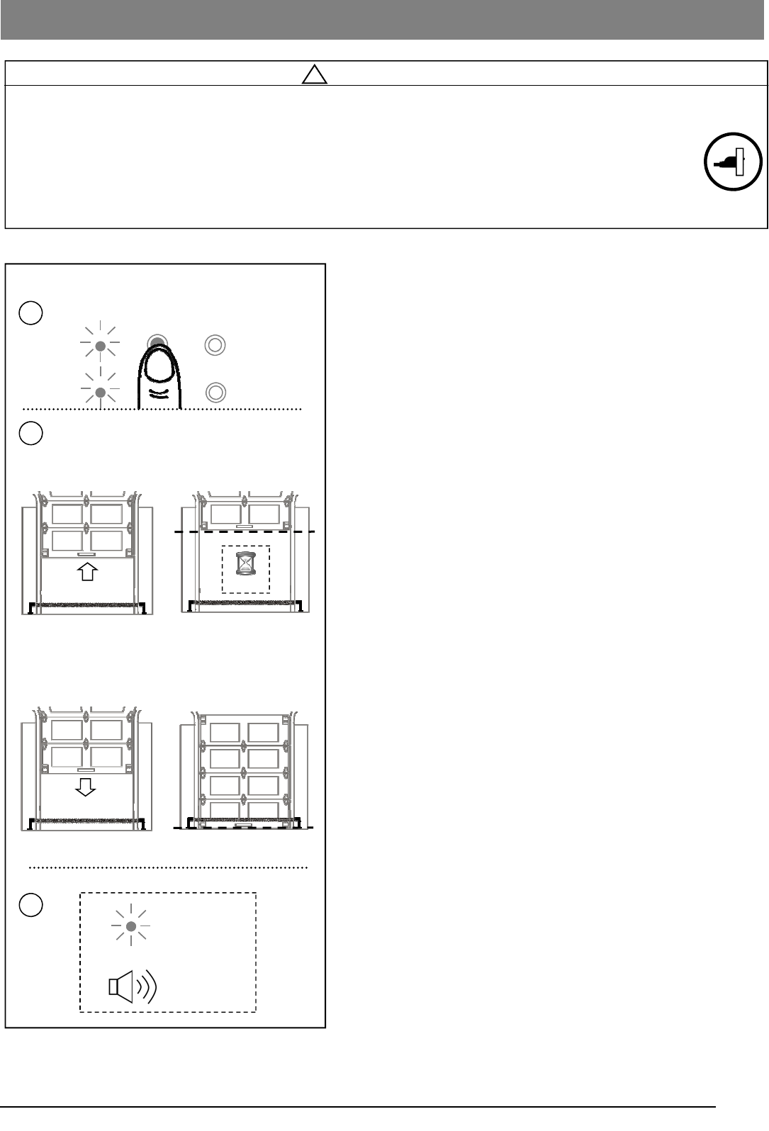
II. Setting DOWN Limit
1. Following UP limit setting, press “LIMIT” button twice to
enter DOWN-limit setting. “DOWN” indicator (red) is on*.
*NOTE: Once you have pressed and released the “LIMIT”
button, it will stay for 10 seconds for you to press the
“DOWN” button and begin programming. If the “DOWN”
light goes out before you are finished you need to start over.
2. Press & hold the “DOWN” button, the door travels down.
You may use both “UP” or “DOWN” buttons to inch-adjust
the door to the desired DOWN limit position.
3. Once the door is at the desired DOWN limit position, press
“LIMIT” button once, “OK” indicator (orange) flashes and
goes off. DOWN limit is set.
Both “UP” and “DOWN” (green and red) indicators are now on,
indicating that both UP and DOWN limits are set, and the opener
is ready for Auto Force Adjustment, see Page19.
NOTICE: The opener will not work until you set the travel limits and the travel force
adjustment.
19
! WARNING
To prevent SERIOUS INJURY or DEATH from improper Force Adjustment:
- DO NOT adjust force to compensate binding or sticking of the garage door. Call a qualified garage door
service person to make necessary adjustments in case of binding.
- DO NOT increase force beyond minimum force required for closing the door. Too much force will cause
improper operation of safety reversal mechanism.
- After ANY adjustments, Safety Reverse Test MUST be performed to ensure the door reverses on contact
with a 1.5” high object (2x4 laid flat).
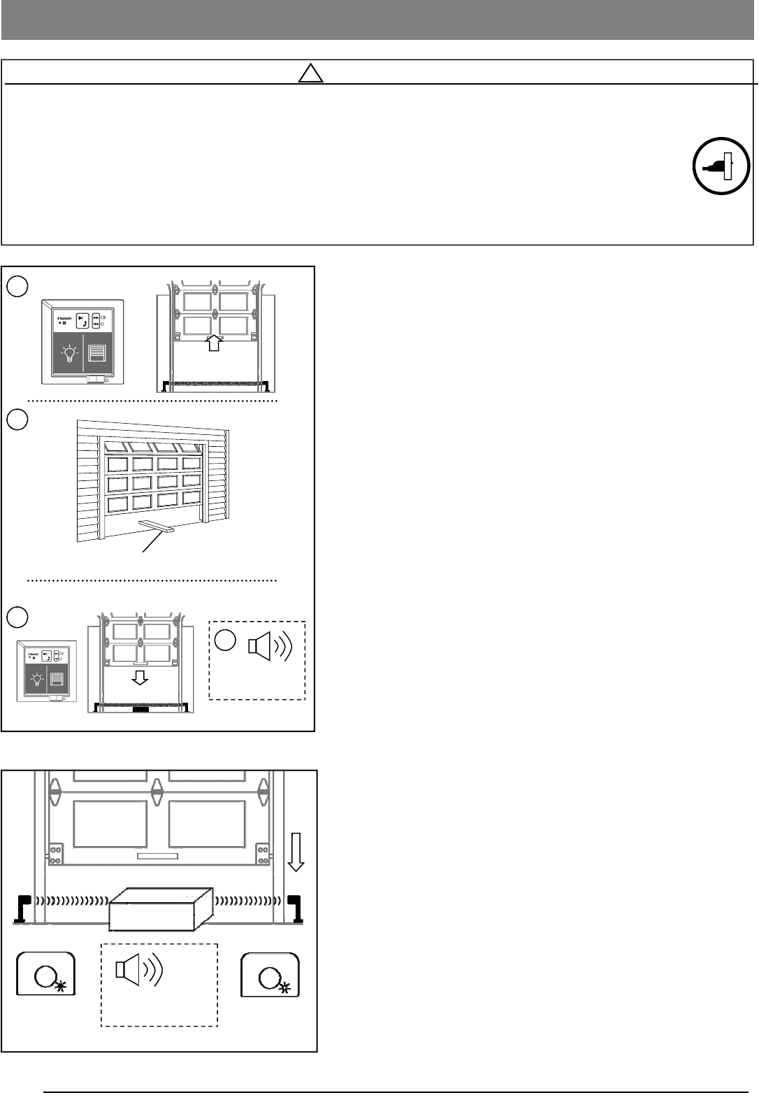
Auto Force Adjustment
Following limit-setting, the unit is now ready to
automatically adjust the forces for opening and closing the
door. Proceed with the following steps to complete
adjustment.
1. With both “UP” and “DOWN” indicators are on after Travel
Limit Adjustment, press the “FORCE” button once to enter
Auto Force Adjustment.
2. The door will travel up automatically (I) and stop at UP
limit for 2 seconds (II). Door will then travel down
automatically (III) and stop at down limit (IV).
3. The “OK” indicator (orange) will flash with beeps, the Auto
Force Adjustment is completed.
2s
Stops at DOWN limit
Travels up
Stops at UP limit for
2 seconds
Travels down
I II
III IV
x2
Flashes
OK
x1
UP
DOWN
FORCE
LIMIT
UP
DOWN
1
2
3
Auto Force Adjustment
20
Final Adjustments and Testing
Testing the Safety Reverse System
The Safety Reverse System prevents the door from closing
when an obstruction is present.
1. Open the door by using the Speaker and Door Control
Console.
2. Place a 1-1/2” (3.8cm) thick solid object (or 2x4 laid flat)
on floor under the center of garage door.
3. Keeping the door in sight, use the Speaker and Door
Control Console to close the door.
4. The door MUST REVERSE and beep within 1.5 seconds
upon striking the object , and stop at the fully open
position.
5. The Safety Reverse System works properly and the
opener is ready to use.
If the door fails to reverse upon contact with obstruction, adjust
the Opener as follows:
The close travel may be inadequate, slightly increase the
DOWN limit. (See Travel Limit Adjustment on page 17-19)
Conduct the test again. If the door reverses on contact, remove
the object and run at least 3 COMPLETE travel cycles to ensure
proper adjustment.
If the Opener still fails the Safety Reverse Test, call a qualified
technician for door adjustment.
Testing the Photo Eye Safety System
1. Open the door by using the Speaker and Door Control
Console.
2. Make sure both Photo Eyes steadily emit the green and
red indicator lights. (If not, check alignment)
3. Place an object under the door about 8” (20cm) high by
12” (30cm) wide (the opener carton can be used),
4. The green indicator light on the emitter eye should flash.
5. The red indicator light on the sensor eye should be
dimmed.
6. Keep the door in sight and use the Speaker and Door
Control Console, Push Button or Control to try to close the
door.
7. The door should NOT move more than 1” (2.5cm) and the
opener will beep.
1-1/2” (3.8cm) thick solid object (or 2x4 laid flat)
Travels up
Travels down
1
3
4
2
Door reverses and
beeps upon strike
OFF
Flashes
Beeps and reverses
upon obstruction
x20
Sensor Emitter
GREEN LIGHT RED LIGHT
! WARNING
To prevent SERIOUS INJURY or DEATH from a closing garage door:
- The Safety Reversal Test MUST be conducted ONCE A MONTH.
- NO ONE should cross the path of moving door during operation and/or testing.
- If either Force or Travel limit adjustment is made, then other adjustment may also be needed.
- After ANY adjustments to the door system, the Safety Reverse Test MUST be performed to ensure the
door reverses on contact with a 1-1/2” thick (2x4 laid flat) object.
- The Photo Eye Safety System MUST be properly aligned, and tested regularly.
21
! WARNING
To Prevent SERIOUS INJURY or DEATH:
- Keep remote control and battery out of reach of children.
- NEVER permit children to access the Speaker and Door Control Console, Push Button nor Remote Controls.
- Operate the door ONLY when it is properly adjusted, and there are no obstructions present.
- ALWAYS keep a moving door in sight until completely closed. NEVER cross the path of a moving door.
To reduce risk of fire, explosion or electric shock:
- DO NOT short circuit, recharge, dissemble or heat the battery.
- Replace with 23AE 12 Volt batteries ONLY. Dispose of batteries properly.
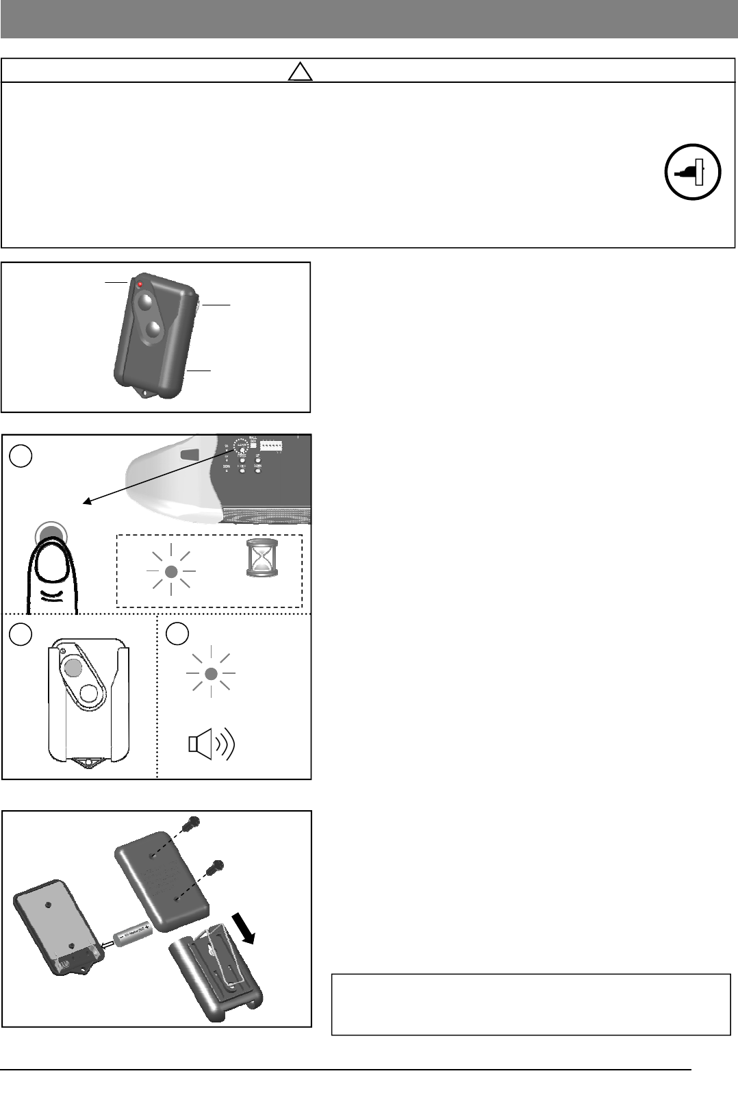
Programming Remote Controls
To Program Remote Control (s):
1. Press/release the “LEARN” button once on the rear control
panel, “OK” LED will glow and beep. The unit is now ready
to accept a remote control in the next 30 seconds as
shown in Fig.2.
2. Press/release any desired button on the Remote Control.
3. The “OK” LED will flash and beep twice indicating
Remote Control is stored successfully.
Up to 20 Remote Controls (including wireless keypad codes)
can be added to the unit by repeating the above procedures.
If more than 20 Remote Controls are stored, the first stored
Remote Control will be replaced. (i.e. the 21st Remote Control
replaces the 1st stored Remote Control .)
Removing ALL Remote Controls:
To remove ALL Remote Controls from memory, press and hold
the “LEARN” button for 5 seconds. The “OK” LED will flash and
beep 2 times indicating. ALL Remote Controls have been
removed from memory.
Replacing Remote Control Battery:
When the battery of the Remote Control is low, the indicator
light will become dim and/or the range of the Remote Control
will decrease. To replace the battery, remove the battery cover
from the Remote Control and replace with a 23AE 12 volt
alkaline battery with polarity shown in Fig.3.
This device complies FCC Rules for HOME OR OFFICE USE. Operation is
subject to the following two conditions: (1) this device may not cause harmful
interference, and (2) this device must accept any interference received,
including interference that may cause undesired operation.
Fig.1
Fig.3
Fig.2
LEARN
30
seconds
OK
1
Visor Clip
Holster
Signal and Battery
Indicator
2
OK
3
x2
x2
22
! WARNING
To Prevent SERIOUS INJURY or DEATH:
- READ AND FOLLOW ALL INSTRUCTIONS AND WARNINGS IN THE OWNER’S MANUAL AND LABELS
- Keep Remote Control and battery out of reach of children.
- NEVER permit children to access the Speaker and Door Control Console, Push Button or Remote Controls.
- Operate the door ONLY when it is properly adjusted, and there are no obstructions and is in clear sight.
- ALWAYS keep a moving door in sight until completely closed. NEVER cross the path of a moving door.
- If Travel limit adjustment is made, Force Adjustment may also needed.
- After ANY adjustments, the Safety Reverse Test MUST be performed to ensure the door reverses on contact
with a 1-1/2” thick object (2x4 laid flat).
- ALWAYS ensure that your door is balanced and in good working condition.
Operating the Opener
Emergency Release Handle
Photo Eye Safety System
Invisible Light Beam
Actual Operating Scenario
Speaker and Door
Control Console
Controls Operation
Speaker and Door
Control Console
Momentary press the “DOOR” button on the Door Control Console, the door starts
to move, and controls as follows:
- Open or close the door.
- Reverse the door while it is closing
- Stops the door while it is opening.
Constant press to close the door when the Photo Eye Safety System is not
installed, misaligned or obstructed INTENTIONALLY. Press and hold the button
until door is fully closed.
Remote Control
Remote distance up to 200ft. in open field.
For safety concerns, the Remote Control WILL NOT work if the Photo Eye Safety
System is not properly installed and aligned.
Wireless Keyless Entry Keypad* Program the Wireless Keyless Entry Keypad accordingly and access the door using
the PIN code.
Activating the Opener
Attach the protective cover to the opener after installation and adjustment is completed.
*Optional
23
Door Status vs. Activation
! WARNING
To Prevent SERIOUS INJURY or DEATH:
- Use Emergency Release to disconnect Trolley ONLY when the door is CLOSED to prevent unexpected rapid falling in
case of a unbalanced / poor-conditioned door.
- Use Emergency Release ONLY when doorway is clear of persons and obstructions.
- DO NOT use Emergency Release to pull the door open or closed.
In case of a power failure or door obstruction, PULL
EMERGENCY Handle to release door from Opener.
To Disconnect Trolley for Manual Operation
With the door closed, pull down the emergency release handle to
the DISCONNECT position. The door can be raised / lowered
manually.
To Re-connect Trolley
Pull the Handle toward the Opener so that the lever will flip up to
the CONNECT position. The Trolley will reconnect itself when the
Opener is activated or when the door is manually opened/closed.
Lever
CONNECT
DISCONNECT
Pull to Disconnect
Flip to reconnect
Manual Operation
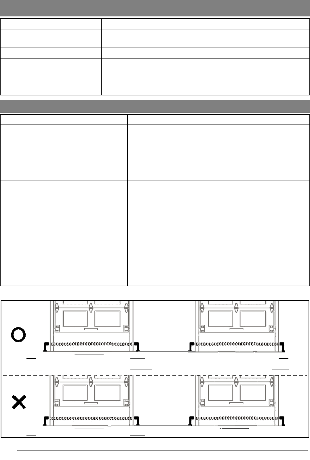
Door status Activation using Speaker and Door
Control Console / Remote Control
Door at fully open / close position Door will move to fully close / open position
Door is closing Door will reverse
Door is opening Door will stop
Door is stopped as intended in partially open position Close
Door is obstructed while closing Door will reverse while flashing courtesy light
Door is obstructed while opening Door will stop
Door is fully opened and Photo Eye System is obstructed Door will not close
Operating the Opener
Operation / Condition
Opener is initially plugged-in (no travel limits stored) Flash x 5
Reconnecting power (with travel limits stored) Flash x 3
“LEARN” button is pressed Beep x 1
Upon activation Light On for 4.5 minutes
Upon activation by remote controls Beep x 1, Light On for 4.5 minutes
Remote Control / Keyless Entry PIN code accepted Beep x 2
Opener is operated without programming Beep x 5
Door travels with abnormal speed Beep x 12 (1 beep / second)
Photo Eye System is obstructed during door-closing Beep x 20
The door is obstructed during travel Beep x 25
Courtesy Light / Buzzer Responses
Courtesy Light / Buzzer Responses
24
Problem Possible Cause / Solution
Opener does not open or close and beeps 5x Reprogram the operator. See pages 17-19.
Opener does not respond to Remote Control - Refer page 21 to reprogram Remote Control.
- Check Remote Control battery.
Opener stops before reaching full open / close
position
Travel Limit is not properly adjusted. This could also be force related.
Check adjustment or reprogram referring to pages 17-19. Conduct
Safety Reverse Test after ANY adjustment.
The door reverses unintentionally
- Make sure the Photo Eye Safety System is aligned and clear of
obstructions.
- If door is replaced or door condition has significant changes,
- Refer to page 4 to check the door balance
- Refer to page 17-19 to re-adjust Travel Limits and Travel Force.
The door reverses upon touching the floor and
the courtesy light flashes Refer to page 17-19 to reset Travel Limits and Travel Force.
The Opener does not close the door and the
indicator on one of the Photo Eyes flashes
The Photo Eye Safety System is misaligned or obstructed, refer to
page16 for proper alignment.
The Opener is working properly but the courtesy
light does not turn on Replace light bulb (A19 incandescent Max.100W).
The courtesy light does not turn off Light relay is stuck. Tap relay on the board to free contact or replace
logic board.
Schedule Maintenance
Once a month Door balance test, refer to page 4.
Safety reverse test, refer to page 20.
Twice a year Check chain/belt tension ( refer to page 6 for adjustment if necessary).
Once a year
- Limit and Force adjustment may be necessary due to weather conditions.
Refer to pages 17-19 for adjustment. Conduct Safety Reverse Test after ANY
adjustments.
- Lubricate door rollers, bearings and hinges. The Opener is permanently
lubricated, DO NOT lubricate or grease the Opener, rail or door tracks.
Maintenance
Red Green LED
Green LED
Green LED
Green LED
Red LED
Green LED
Red LED
Red LED
Green LED
Red LED
Red LED
Note: If installing operators on two doors in the same garage, to ensure proper operation, Photo Eyes should
be aligned as below:
Troubleshooting
See additional trouble shooting tips on the www.adhguardianusa.com website.
25
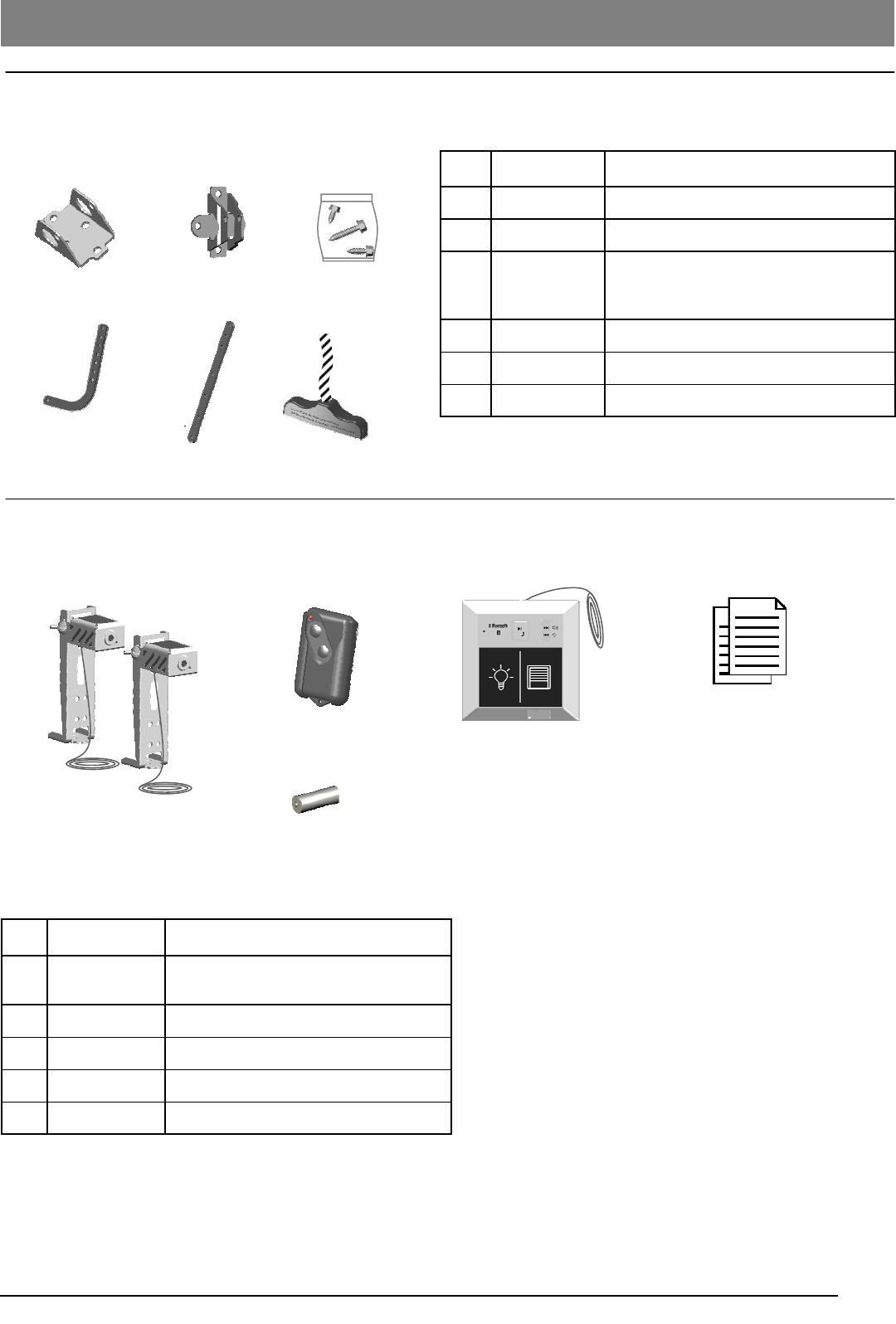
Installation Parts
Accessories
Item Part No. Name / Description
1 GUAT-027 Header Bracket
2 GUAT-022 Door Bracket
3 GUAT-023 Hardware Bag
(Installation hardware shown on P.3)
4 GUAT-024 Curved Door Arm
5 GUAT-025 Straight Door Arm
6 GUAT-026 Emergency Release Handle & Rope
Item Part No. Name / Description
1 GUAT-201 Photo Eye Safety System
(Emitter + Sensor with Brackets)
2 GDOR2B Remote Control
3 GUDT-203 12V AE23 Alkaline Battery
4 GUDT-212 Speaker and Door Control Console
5 GUDT-213 Owner’s manual
1 2 3
4 5 6
1 2
3
5
Repair Parts
4
26
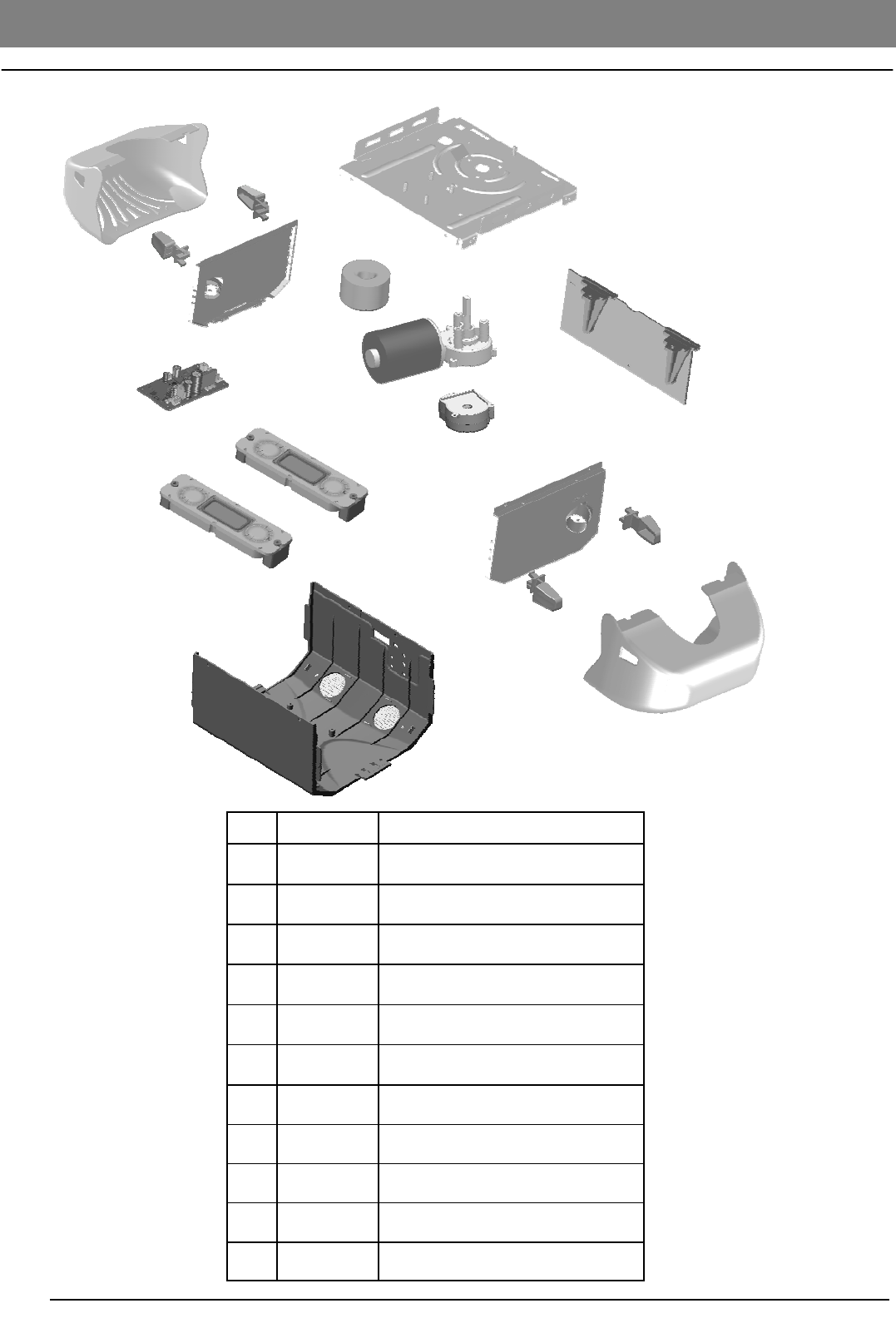
Opener Assembly Parts
Item Part No. Name / Description
1 GUDT-301 Chassis
2 GUDT-302 Transformer
3 GUDT-312 Logic Board
4 GUDT-313 DC Motor (with encoder shaft)
5 GUDT-314 Encoder Module
8 GUDT-324 Opener Cover
9 GUDT-309 Lamp Plate
10 GUDT-310 Light Lens Cover
11 GUDT-311 Light Lens Clip
13 GUDT-327 Speaker Unit
12 GUDT-325 Bluetooth & Amplifier Board
1
2
4
3
9
8
10
11
5
12
13

27
FCC Statement
Manufacturer hereby warrants:
Any Changes or modifications not expressly approved by the party responsible for compliance could void the user’s
authority to operate the equipment.
This equipment complies with FCC radiation exposure limits set forth for an uncontrolled environment. This equipment
should be installed and operated with minimum distance 20cm between the radiator& your body.
This transmitter must not be co-located or operating in conjunction with any other antenna or transmitter.
This device complies with part 15 of the FCC Rules. Operation is subject to the following two conditions:
(1) This device may not cause harmful interference, and (2) this device must accept any interference received, including
interference that may cause undesired operation.
This equipment has been tested and found to comply with the limits for a Class B digital device, pursuant to part 15 of
the FCC Rules. These limits are designed to provide reasonable protection against harmful interference in a Residential
installation. This equipment generates uses and can radiate radio frequency energy and, if not installed and used in
accordance with the instructions, may cause harmful Interference to radio communications. However, there is no
guarantee that interference will not occur in a particular installation. If this equipment does cause harmful interference to
radio or television reception, which can be determined by turning the equipment off and on, the user is encouraged to try
to correct the interference by one or more of the following measures:
—Reorient or relocate the receiving antenna.
—Increase the separation between the equipment and receiver.
—Connect the equipment into an outlet on a circuit different from that to which the receiver is connected.
—Consult the dealer or an experienced radio technician for help.

Manufacturer hereby warrants:
1. Garage Door Operators to be free from defects in material and workmanship for a period of five (5) years for motors and
one (1) year for Electronics and Mechanics from date of purchase, if installed by an authorized reseller, otherwise if
installed by the purchaser one (1) year will apply.
2. Garage Door Operators (Commercial and Industrial Application) to be free from defects in material and workmanship for
a period of three (3) months from date of purchase.
3. Where the garage door operator has been returned to the manufacturer for Warranty repairs, all costs incurred in the
return will be paid for by the purchaser. If in the opinion of the manufacturer the product is faulty, all defective parts will
be replaced at no charge to the purchaser.
4. Proof of purchase must be given to the manufacturer at time of Warranty claim.
5. The manufacturer reserves the right to modify any existing or future products without incurring any obligation to
incorporate such modification to products already manufactured or to which this Warranty may relate.
6. Warranty only applies if this product has been installed to the Manufacturers recommendation
7. This Warranty does not apply to any defect, loss or damage arising or caused directly or indirectly by or as a result of :
(i) Any defect (including detects in component parts or accessories) arising from or attributable to the failure to carry
out normal preventive maintenance or adjustment itself.
(ii) To any additional damage or deterioration arising from attributable to the operation of the Operator after it is known
to be defective.
8. Exclusions to Warranty Period:
(i) Repair or Warranty Work - three (3) month
9. Not included in Warranty:
(i) Batteries.
(ii) Fuses.
(iii) Light bulbs.
(iv) Sensitivity adjustment.
(v) Handheld Remote Controls and receiver range.
10. Note : All Warranties will be void subject to:
(i) Water damage and condensation.
(ii) Power supply black out or surge.
(iii) Act of God.
(iv) Modification or adjustment by unauthorized persons.
(v) Any interference from radio (including citizen band radios or and other electronic device)
(vi) Preventative maintenance and regular servicing not undertaken.
(vii) Account not paid in full by the purchaser.
11. Subject only to the provisions of the Trade practices Act and any legislation of the State or Territory wherein the
operators of the Manufacturer have been sold or installed (which may confer certain rights on consumers of goods
and those rights by such legislation may be rendered incapable of exclusion) this Warranty supersedes and excludes
all representations, warranties and conditions whether expressed or implied by law and the Manufacturer shall have
no liability or otherwise than herein provided for any loss and damage (including consequential loss and damage, loss
of use or profits) by reasons of delay, defective or faulty materials or workmanship, negligence or any act, matter or
thing done permitted or omitted to be done by the Manufacturer.
WARRANTY
THIS WARRANTY FORM SHOULD BE COMPLETED AT TIME OF INSTALLATION
This Warranty Form should be retained by the purchaser at all times and produced with the purchase docket by the
Purchaser as proof of the purchase date.
PURCHASER’S NAME:
PURCHASER’S ADDRESS:
INSTALLED BY:
INSTALLER’S ADDRESS:
INSTALLER’S SIGNATURE:
SERIAL NUMBER OF THE OPERATOR:
GUARDIAN SERVICE
Your operator has been installed by a professional installation specialist. If service information is required please contact
the installing company or your local Guardian dealer. Look for your Guardian dealer online, in the yellow pages or call our
service number for a dealer near you.
Service number : 1-424-272-6998
Please have the following information when you call:
·Model number of the operator
·Serial number of the operator--located on the bar code label on top of the opener, above the adjustment buttons
WARRANTY
GARAGE DOOR OPERATORS