GUARDIAN DCRX01-CC Garage Door Opener User Manual L5112 T GU 615 150710
GUARDIAN SHANGHAI CORP. Garage Door Opener L5112 T GU 615 150710
UserManual.wiki
>
GUARDIAN
>
DCRX01 CC User Manual
Users Manual
Navigation menu
Upload a User Manual
Namespaces
Wiki Guide
HTML
PDF
Info
Views
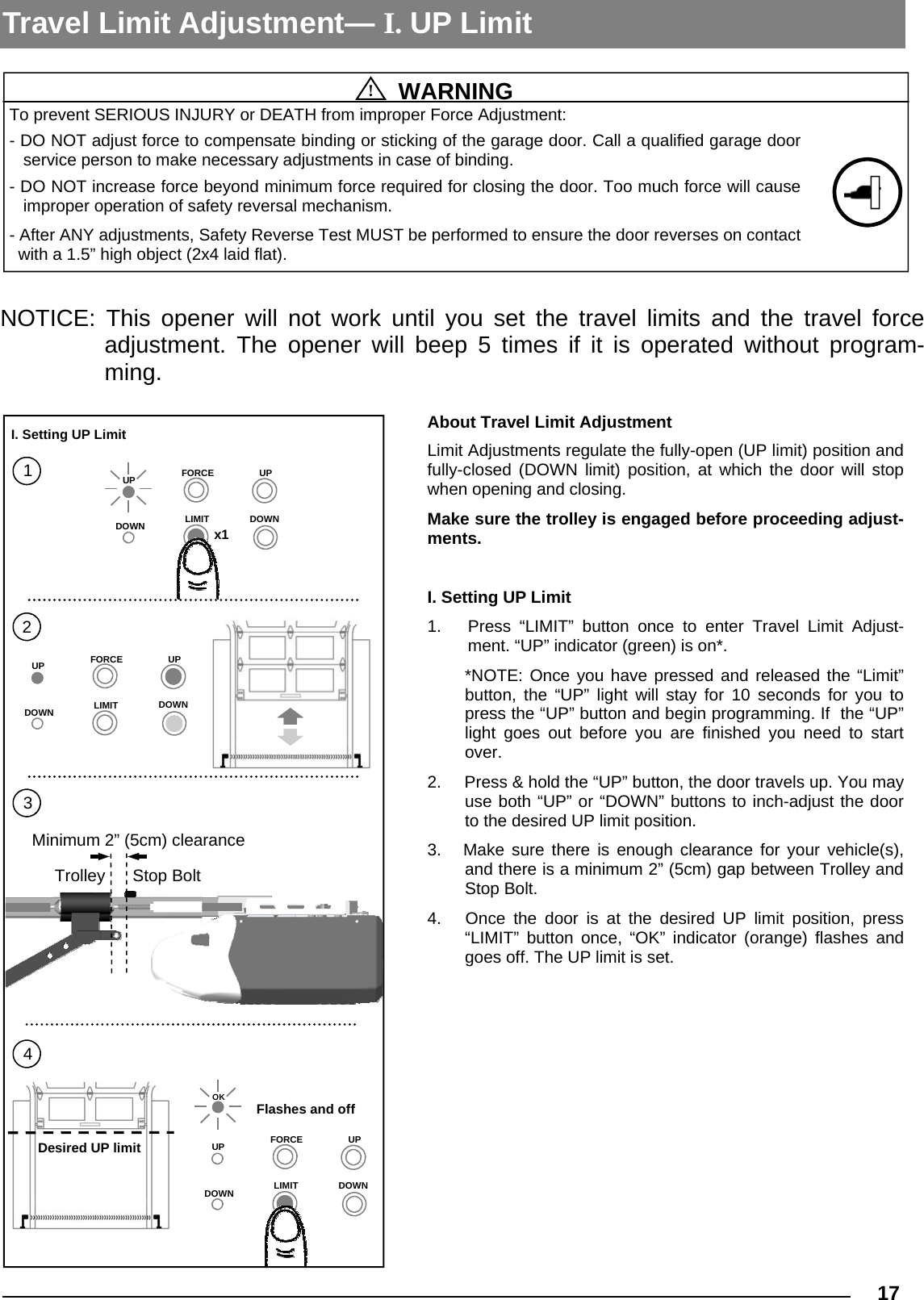
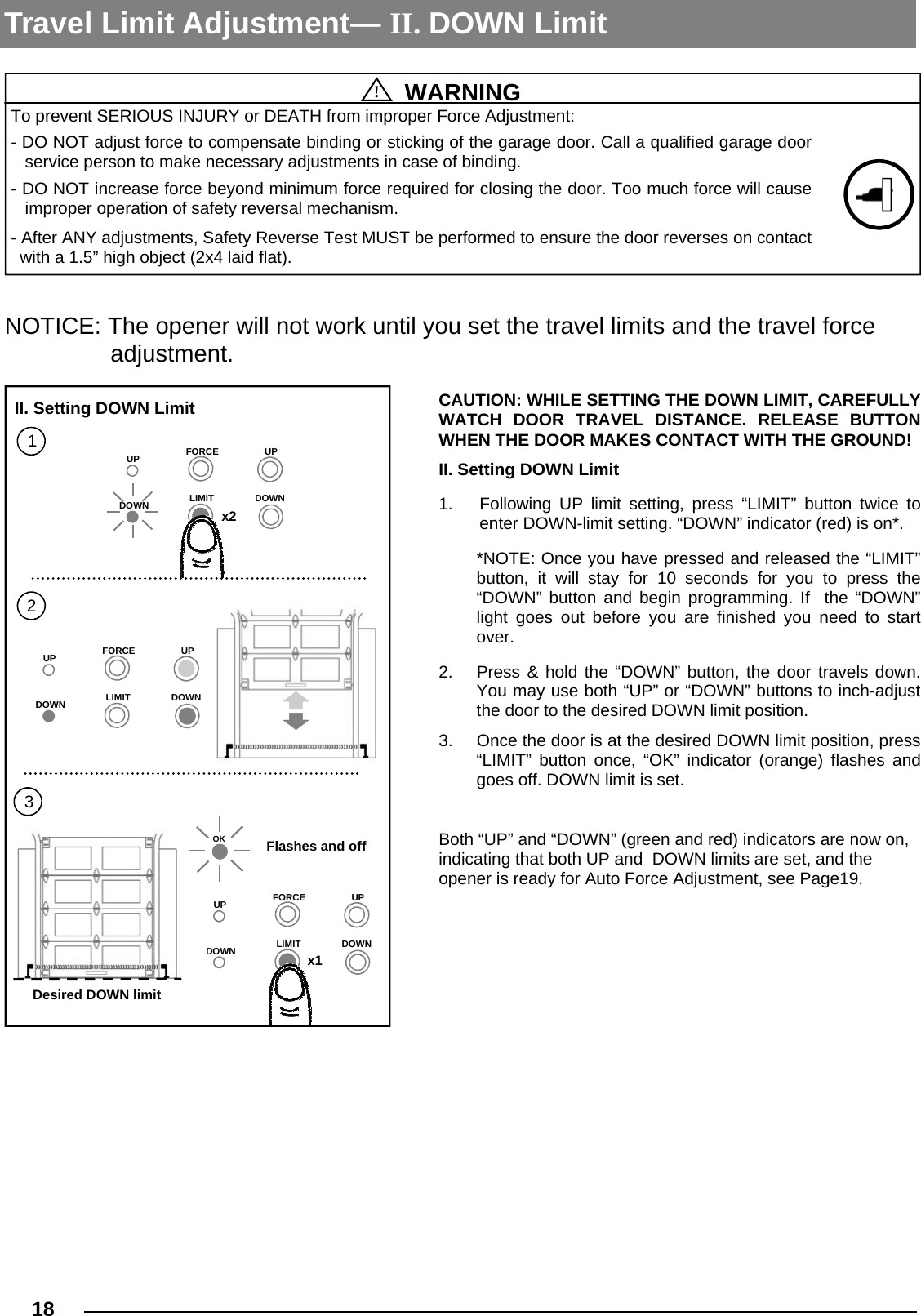
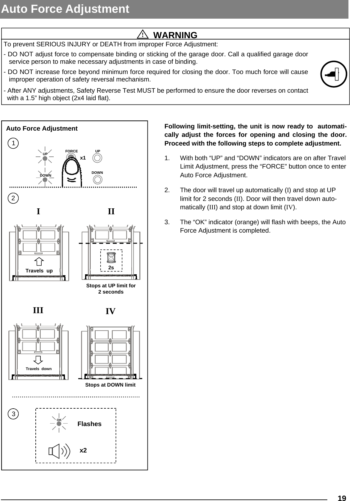
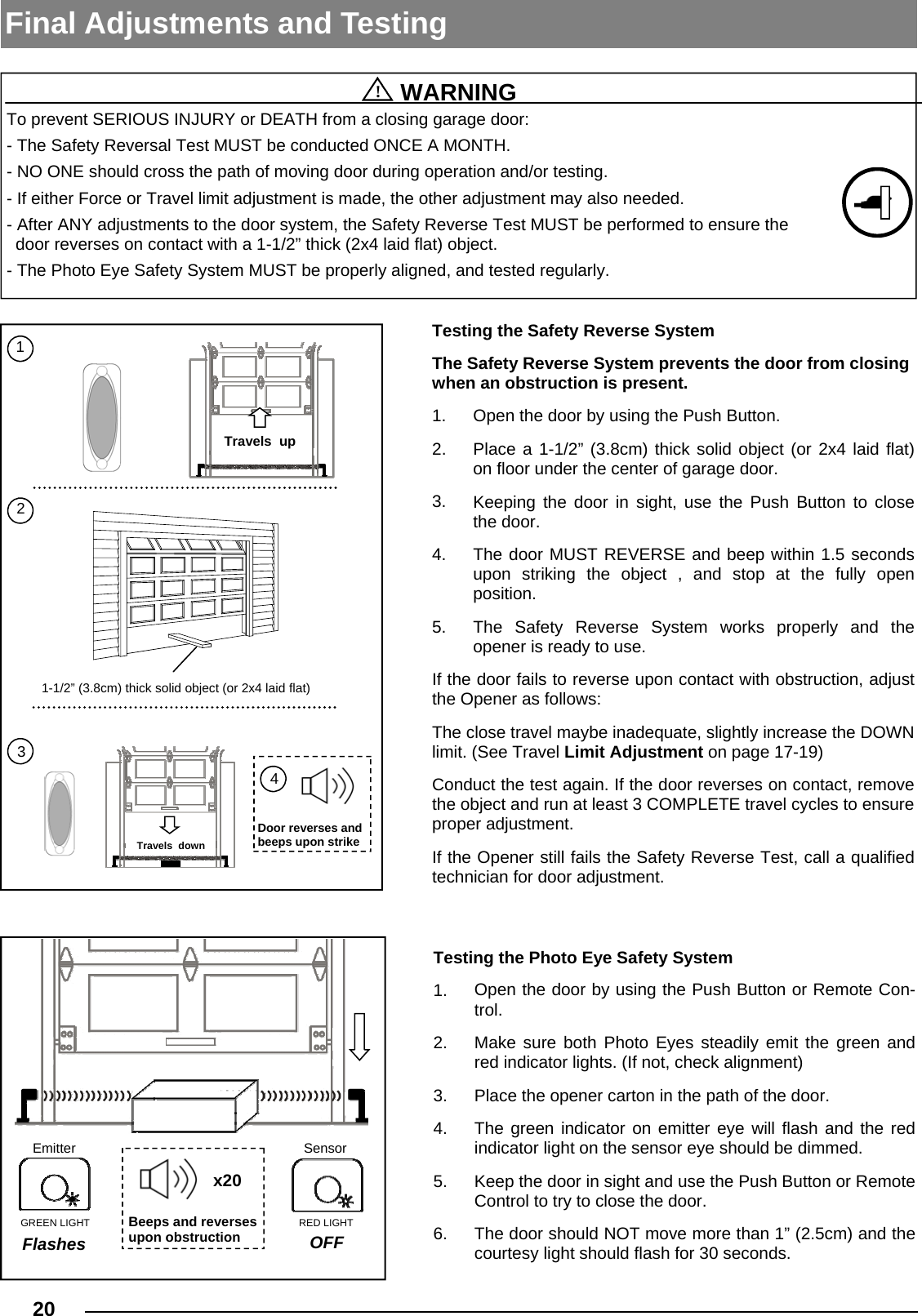
User Manual
Discussion / Help
Navigation