GVC EPIQ-694 EPIQ Computer User Manual MR804manualX01
GVC International U.S.A., Inc. EPIQ Computer MR804manualX01
UserManual.wiki
>
GVC
>
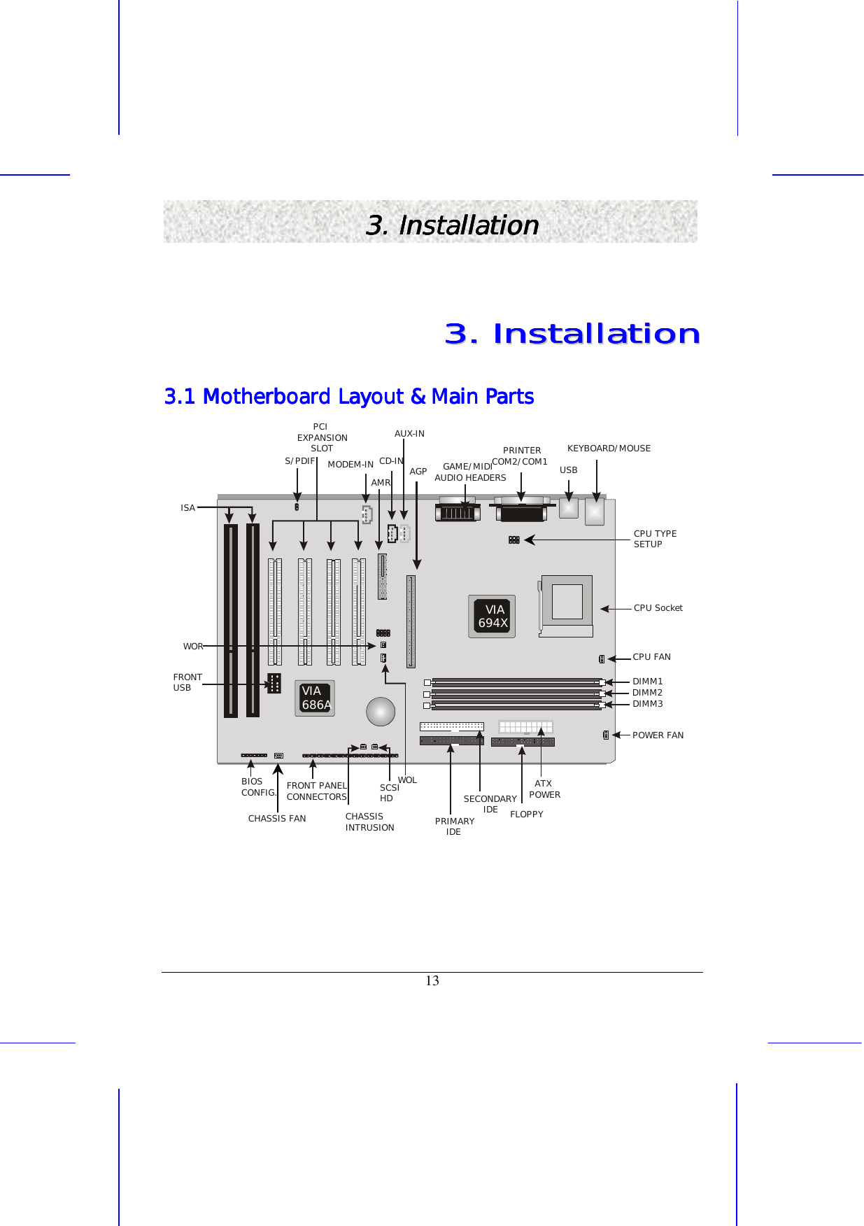
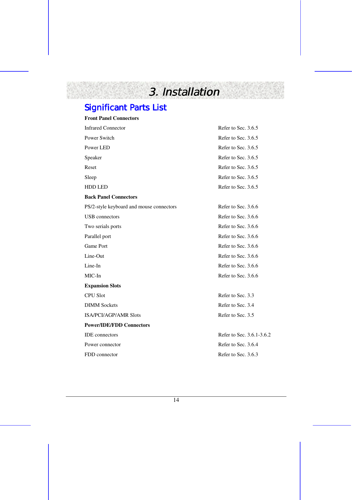
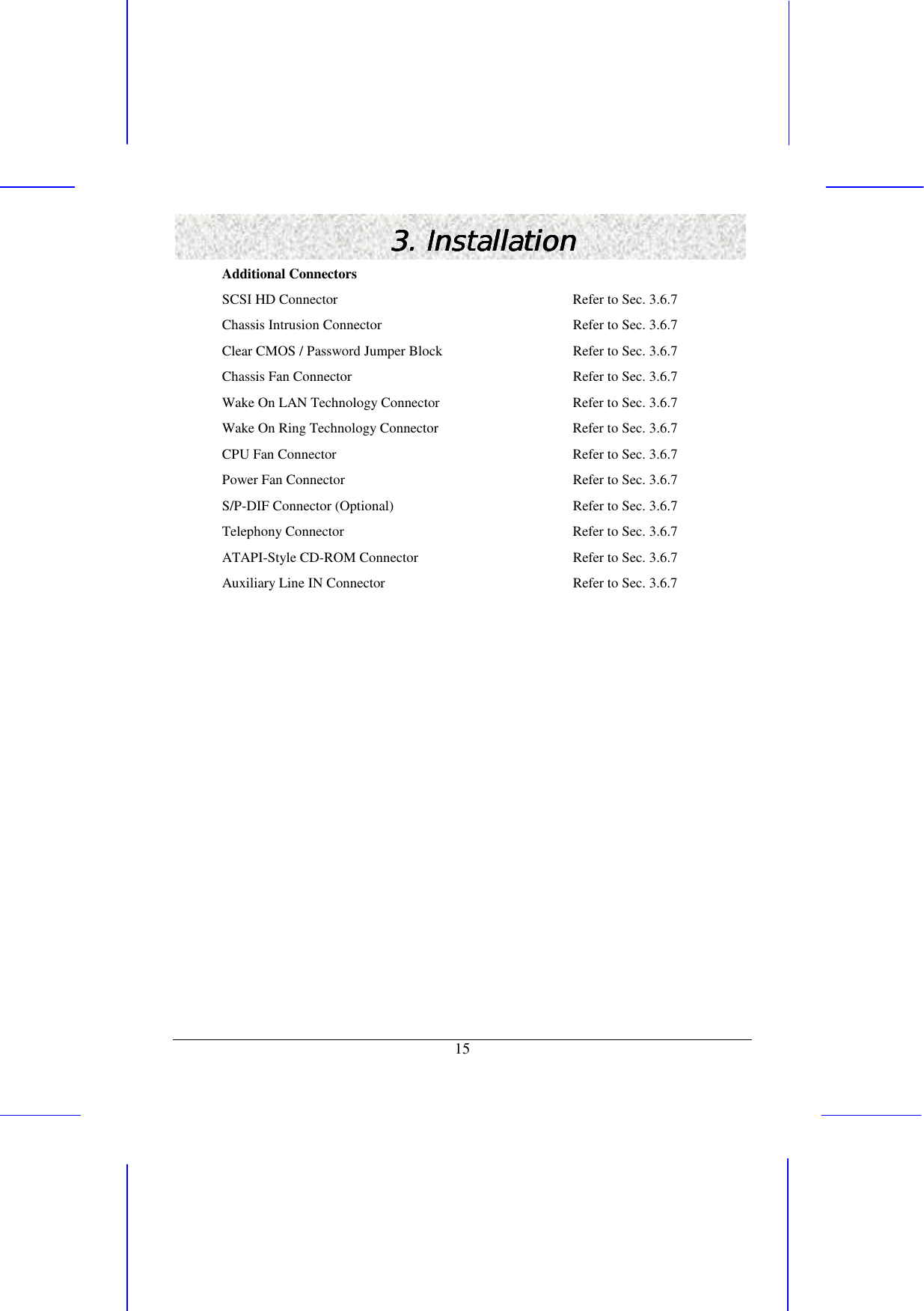
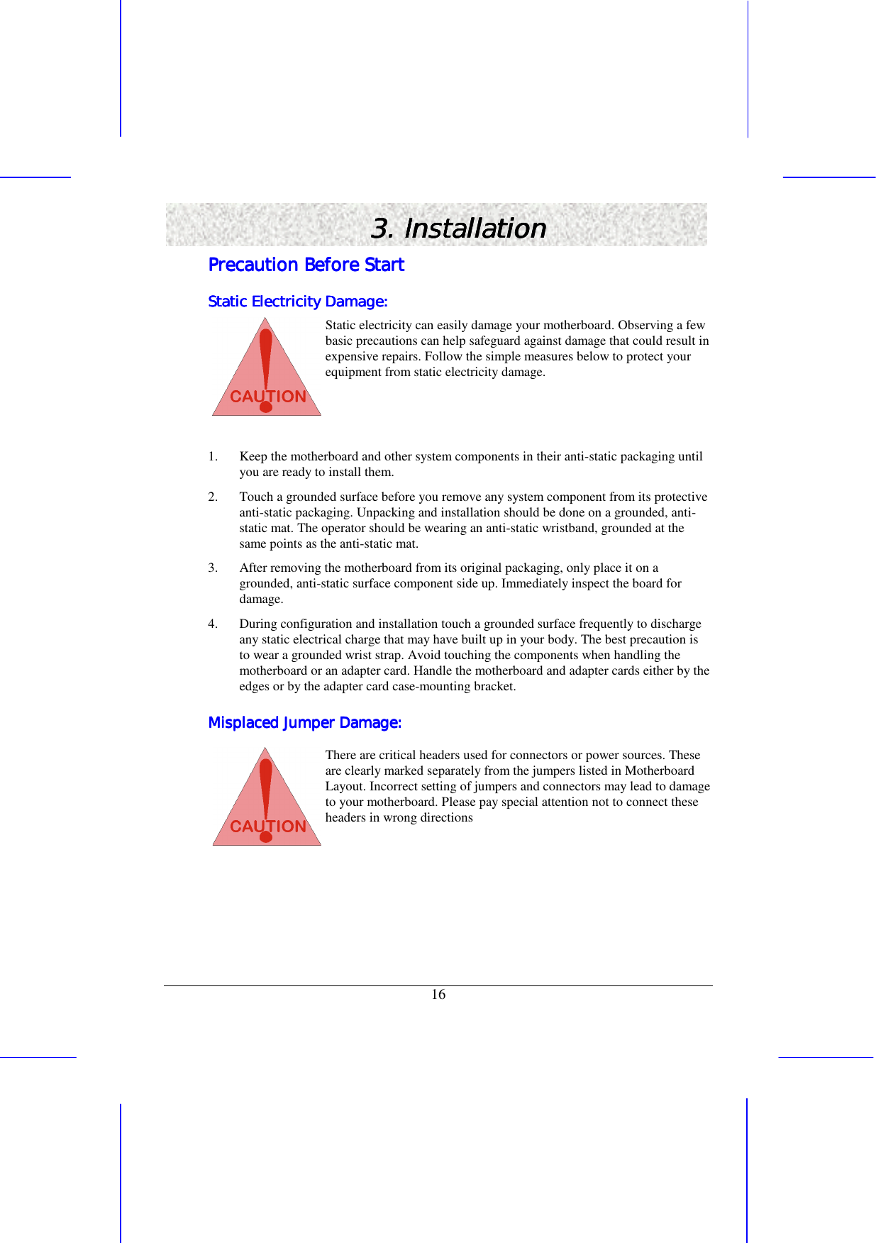
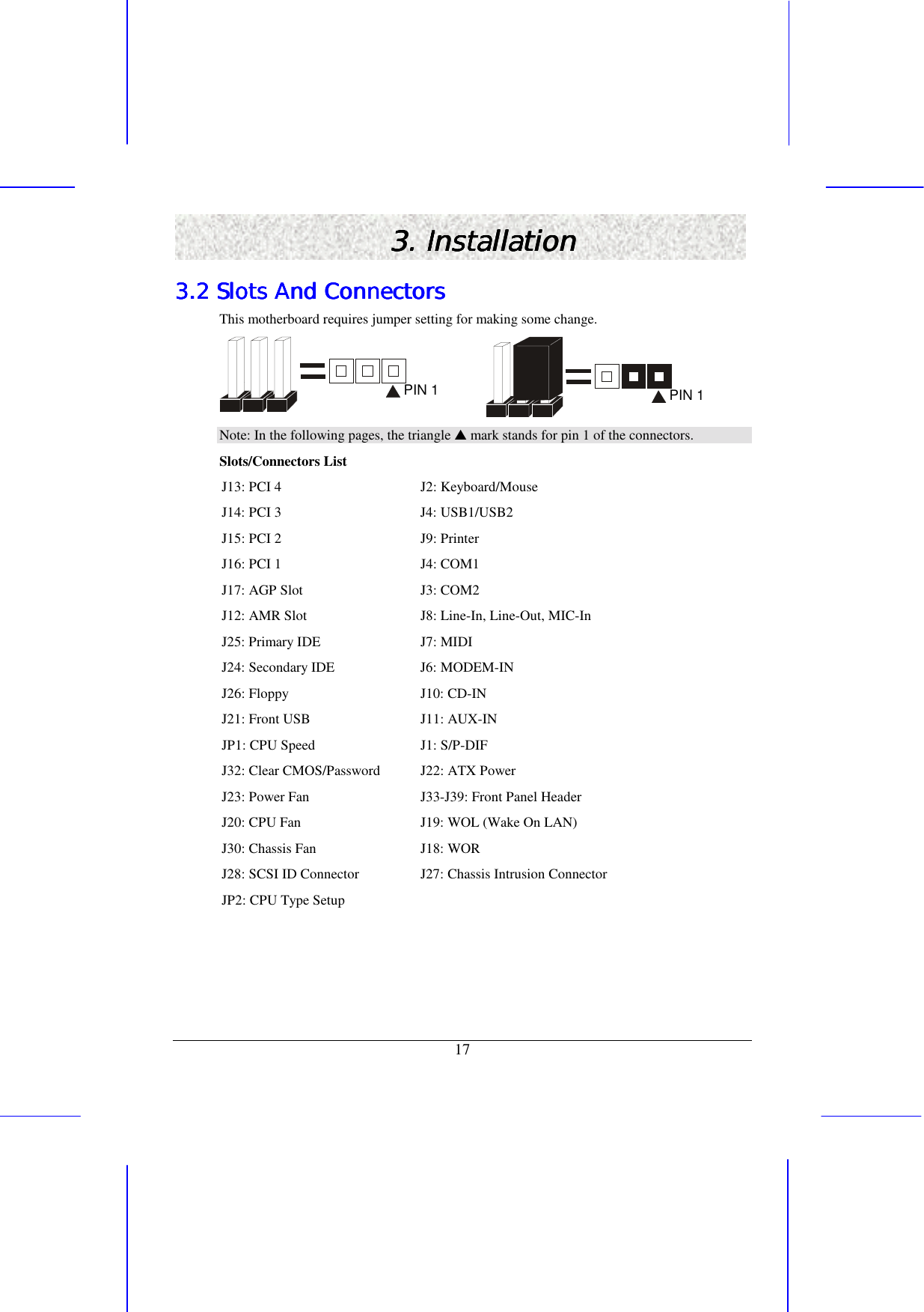
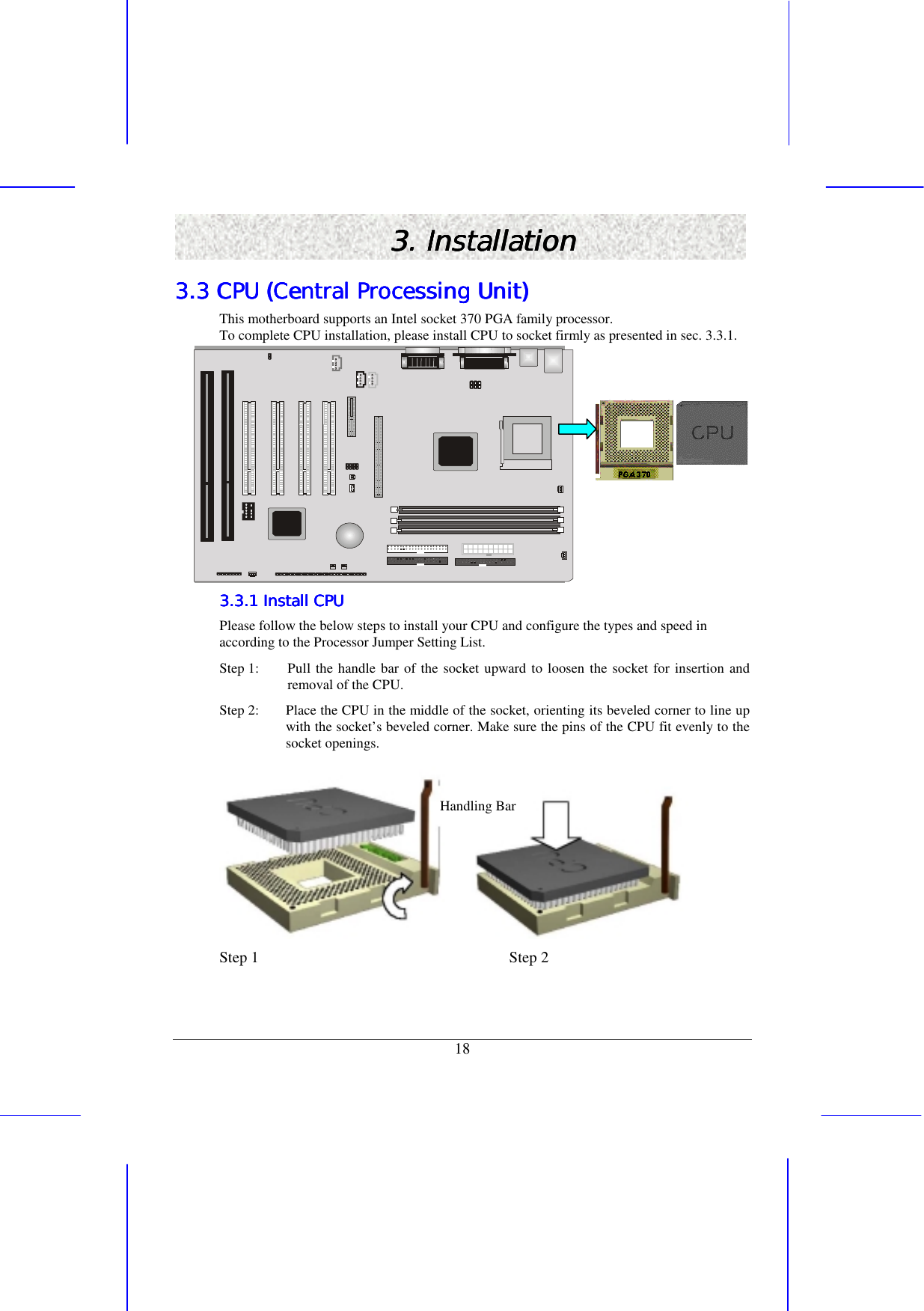
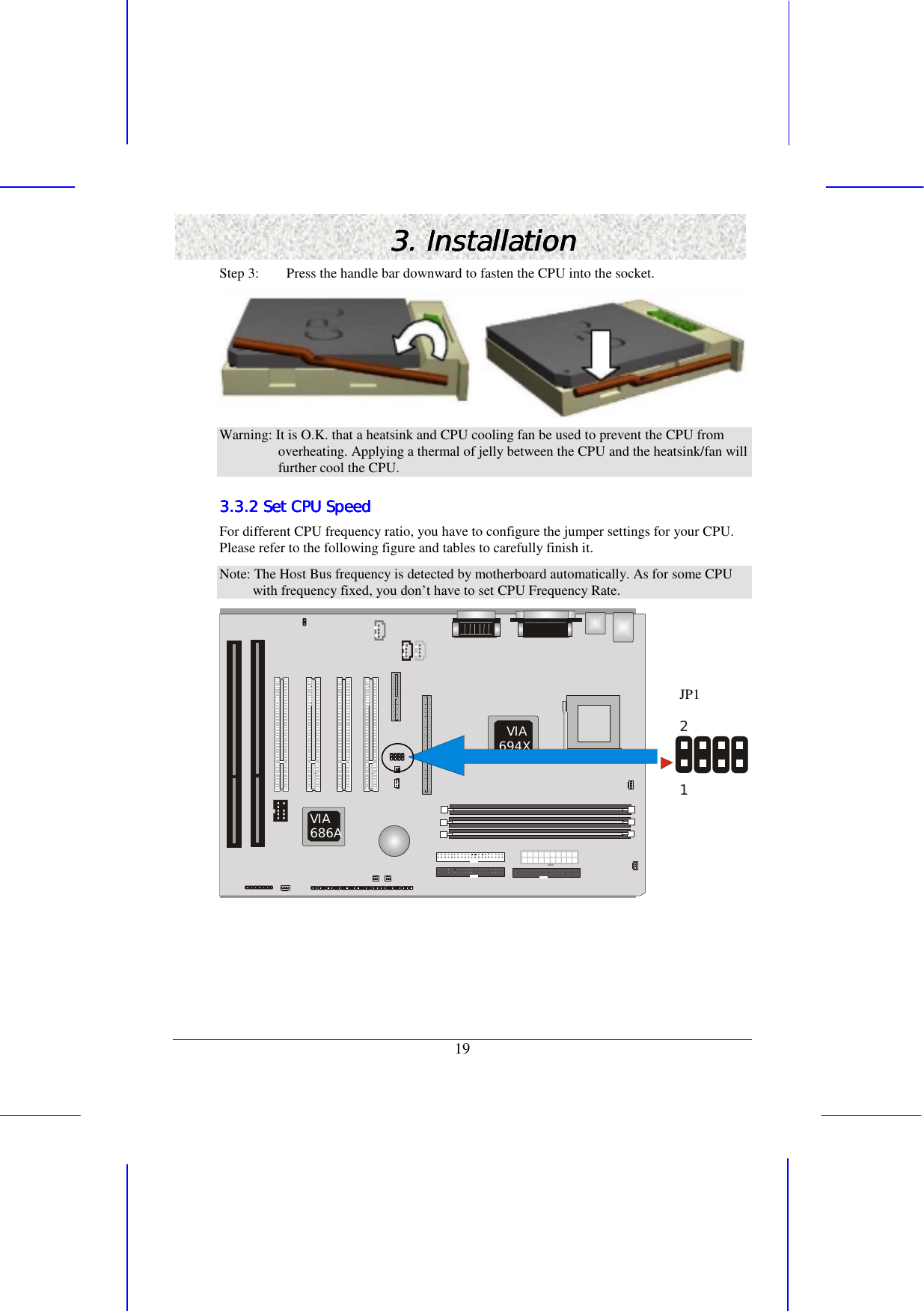
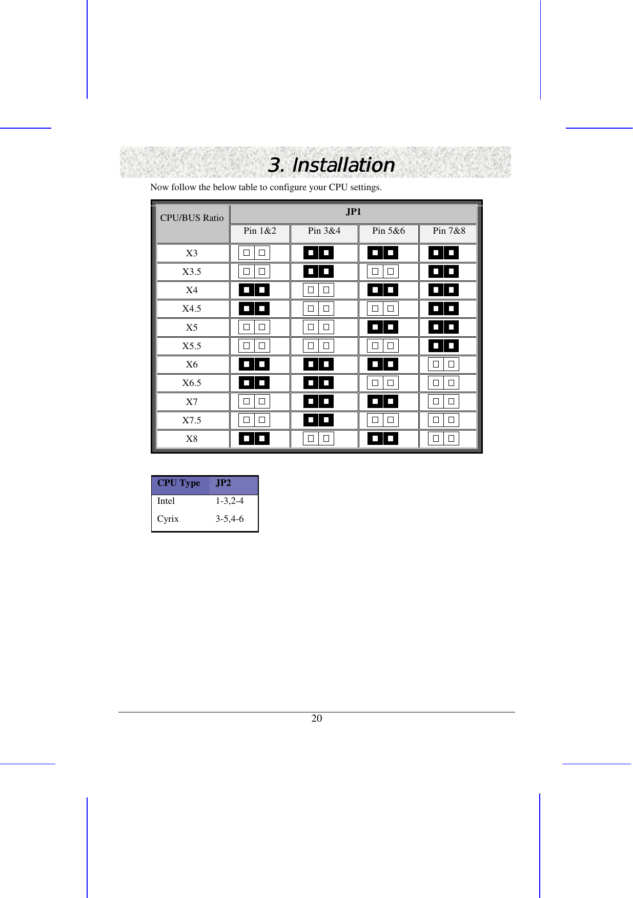
EPIQ 694 User Manual
manual
Navigation menu
Upload a User Manual
Namespaces
Wiki Guide
HTML
PDF
Info
Views
User Manual
Discussion / Help
Navigation