Galaxy Tracking Systems VTRAKH450 UHF-FM VehicleTracking Unit User Manual INTRODUCTION
Galaxy Tracking Systems L.L.C. UHF-FM VehicleTracking Unit INTRODUCTION
Contents
- 1. Users Manual1
- 2. Users Manual2
- 3. Service Manual
Users Manual2
Appendix A
User’s Manual

Vehicle Location and Tracking System
(VLaTS)
Vehicle Transceiver Unit (VTU)
User’s Guide
Preliminary
7 Sept 1999
Prepared For:
Galaxy Tracking Systems, L.L.C.
2500 English Creek Ave., Bldg C
Egg Harbor Twp., NJ 08234-5562
(609) 645-0900
FAX (609) 645-3316
Prepared By:
Galaxy Scientific Corp.
600 Louis Drive, Suite 202
Warminster, Pa 18974
(215) 672-8005
FAX (215) 672-8708
Email: TechSupport@GalaxyScientific.com
The data contained in this document is proprietary to Galaxy Tracking Systems,
L.L.C. Use or disclosure of this data beyond the purposes of the performance of
the tasks defined herein without written permission is prohibited.
Table of Contents
1 INTRODUCTION ..................................................................................................................................1
2 SCOPE .................................................................................................................................................1
3 APPLICABLE DOCUMENTS...............................................................................................................1
4 SPECIFICATIONS................................................................................................................................1
5 SYSTEM OVERVIEW...........................................................................................................................3
5.1 MOBILE COMPONENTS ........................................................................................................................3
5.2 FIXED COMPONENTS ...........................................................................................................................3
5.3 RF TRANSMISSION SCHEME ................................................................................................................4
5.4 SYSTEM TIMING ..................................................................................................................................4
6 VTU COMPONENTS............................................................................................................................5
6.1 VTU SYSTEM ENCLOSURE ..................................................................................................................5
6.1.1 GPS Receiver ..........................................................................................................................5
6.1.2 Radio........................................................................................................................................5
6.1.3 System Controller ....................................................................................................................6
6.2 ANTENNAS AND CABLES ......................................................................................................................6
6.3 OPTIONAL COMPONENTS.....................................................................................................................6
6.3.1 Switch Box (Alarms and Indicators).........................................................................................6
6.3.2 Relay Box (Vehicle Controls)...................................................................................................6
7 VTU CONNECTORS AND CONNECTIONS........................................................................................7
7.1 INPUTS ...............................................................................................................................................9
7.2 OUTPUTS .........................................................................................................................................10
7.3 POWER ............................................................................................................................................10
7.4 ANTENNAS........................................................................................................................................10
8 VTU OPERATIONS............................................................................................................................11
8.1 VTU STARTUP..................................................................................................................................11
8.2 VTU OPERATING MODES ..................................................................................................................11
8.2.1 OUT OF SERVICE Operating Mode......................................................................................11
8.2.2 IN SERVICE Operating Mode................................................................................................12
Galaxy Tracking Systems, L.L.C. VTU User’s Guide
4
Use or disclosure of data contained on this sheet is subject to the restriction on the title page of this report.
Figure 1 - Vehicle Location and Tracking System Architecture.......................................3
Figure 2 - Vehicle Transceiver Unit (VTU).......................................................................5
Figure 3 VTU INPUT PIN DEFINITIONS - 10 pin BROWN Molex Connector.................7
Figure 4 VTU POWER CONNECTOR PIN DEFINITIONS - 4 pin WHITE Molex
Connector.................................................................................................................8
Figure 5 VTU OUTPUT PIN DEFINITIONS - 8 pin BROWN Molex Connector...............9
Galaxy Tracking Systems, L.L.C. VTU User’s Guide
1
Use or disclosure of data contained on this sheet is subject to the restriction on the title page of this report.
1 INTRODUCTION
This document is intended to provide a description of the operation and interfaces of
the Vehicle Transceiver Unit (VTU).
2 SCOPE
This document describes the operation and use of the Vehicle Transceiver Unit (VTU).
3 APPLICABLE DOCUMENTS
Vehicle Location and Tracking System (VLaTS)
Vehicle Tracking Unit (VTU) Installation Guide Revision 1
24 February 1999
Vehicle Location and Tracking System (VLaTS)
Mobile Tracking Unit (MTU) User’s Guide
7 Sept 1999
4 Specifications
Size 17.5 x 10 x 6 cm
Weight 650 grams w/o cabling
Primary Power Automotive 12 VDC
Backup Power Rechargeable Lead Acid Battery (2 Amp-Hrs)
Power Consumption (all at 12V) 1.2 amps peak during RF transmit
330 milliamps quiescent
180 milliamps in sleep mode max
Operating Temperature Range -30 to 60 celsius
Humidity 95% RH non condensing
Vibration 1 Hz to 10 Hz, 25mm displacement
10Hz to 1 kHz, 2G
Shock 12G half sine wave, 12 msec
RF 450-470 Mhz Transceiver
Galaxy Tracking Systems, L.L.C. VTU User’s Guide
2
Use or disclosure of data contained on this sheet is subject to the restriction on the title page of this report.
25 kHz channel spacing
2 watt transmitter
GMSK modulation, 9600-baud data rate
Bit scrambling, FEC and Data interleaving employed
GPS Motorola GT+ 8 channel C/A code receiver
Differential positioning
Inputs 4 optically isolated discretes
1 TTL level programming input / output
Optically isolated ignition sense
Outputs 7 TTL level discretes
1 TTL level discrete power / Tx indicator output
Galaxy Tracking Systems, L.L.C. VTU User’s Guide
3
Use or disclosure of data contained on this sheet is subject to the restriction on the title page of this report.
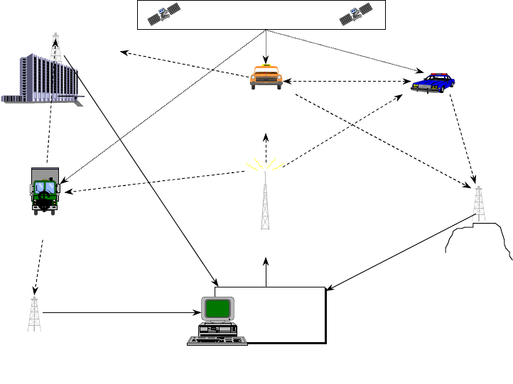
5 SYSTEM OVERVIEW
A typical configuration of Galaxy’s vehicle tracking system is illustrated below.
CENTRAL
COMMAND
CENTER
(CCC)
CENTRAL
COMMAND
CENTER
(CCC)
CENTRAL BROADCASTING
UNIT (CBU)
GPS SATELLITE NETWORK
FIXED TRACKING
UNIT (FTU)
FTU
FTU
DIGITAL DATA
LINK (DDL)
DDL DDL
DDL
Private Vehicle
Transceiver Unit
(VTU) Mobile
Tracking
unit
(MTU)
RF
RF
RF
RF
RF
Fleet Vehicle
Tranceiver Unit
(VTU)
GPS
GPS
RF
Figure 1 - Vehicle Location and Tracking System Architecture
5.1 Mobile Components
The Vehicle Transceiver Unit (VTU) is the mobile component of Galaxy’s vehicle
location and tracking system. Each VTU contains a GPS receiver to determine location,
and a UHF radio for communications. VTUs run directly off of vehicular battery power
and are small enough to be easily hidden.
Vehicles equipped with VTUs can be commanded to continuously report their position,
speed, and status.
For anti-theft and security related applications, the VTU can provide limited remote
control of vehicle systems (e.g., lights, horn or ignition), as well as automated and
manual alarms.
5.2 Fixed Components
The tracking system’s infrastructure is comprised a powerful transmitter, Central
Galaxy Tracking Systems, L.L.C. VTU User’s Guide
4
Use or disclosure of data contained on this sheet is subject to the restriction on the title page of this report.
Broadcasting Unit (CBU), and a host of fixed receivers, Fixed Tracking Units (FTUs),
placed strategically throughout the area of operations to ensure uninterrupted
communications to member vehicles. The CBU operates under the direct control of the
Central Command Center (CCC) which provides the primary operator interface to
command and control the system. The CBU transmits aiding data, system timing data
and VTU commands at precise intervals synchronized to GPS time.
Every VTU command requires an acknowledgment back to the CCC. The exact time
and interval at which the VTU is to transmit its response(s) is contained in the original
VTU command. Vehicle (VTU) transmissions are received by FTU(s) and forwarded by
direct cable connection or telephone line back to the CCC.
5.3 RF Transmission Scheme
Galaxy’s system currently supports sixteen radio channels. Each channel is comprised
of a receive / transmit frequency pair within the radio’s operating frequency range. Each
channel is divided using a Time Division Multiple Access (TDMA) transmission scheme
that begins on a one-hour boundary and repeats every 30 seconds. Each 30-second
cycle is divided into five six-second frames. The frames are further divided into 100
msec “slots”.
The first six time slots of each frame are allocated to CBU transmissions. The
remaining time slots are allocated dynamically to specific VTUs under control of the
command center.
5.4 System Timing
Accurate time is required to maintain the TDMA transmission scheme employed for
UHF communications. All system components are synchronized to within a few
milliseconds of each other using the GPS 1 PPS output pulse.
Galaxy Tracking Systems, L.L.C. VTU User’s Guide
5
Use or disclosure of data contained on this sheet is subject to the restriction on the title page of this report.
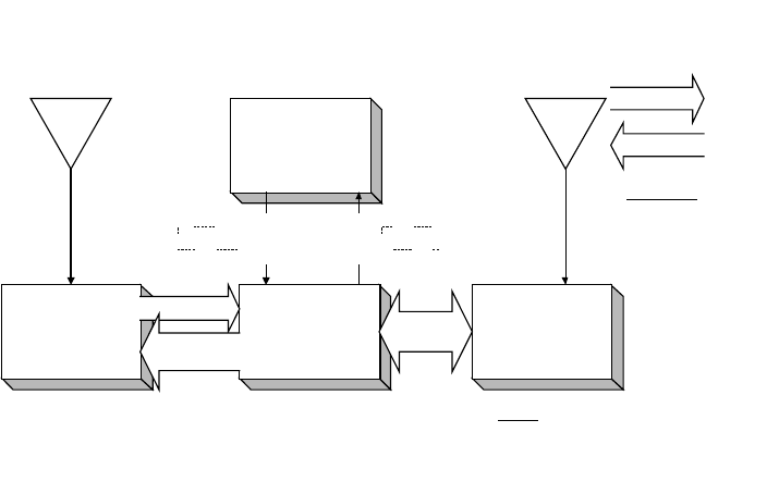
6 VTU Components
GPS Subsys tem
(GPS Receiv er) Digital B aseband
Subsyst em
(Micro Controller)
p,v,t
ID, stat us Comm unicati ons
Subsystem
(Radio Modem)
Packets ,
Timing data /
control
Feat ures
3 Freq between (450-470 Mhz)
960 0 baud GMSK modulati on
Forward Error Correcti on (Hamming c ode, Data Int erleavi ng)
2 watt transmit power
20 K range
GPS
VLaTS Vehicle Tracking Unit (VTU)
p,v,t, ID,st atus
Commands,
Timing
Stat us I ncludes:
H ardware st at us
GPS Tracki ng s tat us
Discretes status
Configur ati on,
Initialization,
GPS Correcti ons
Vehicl e
Movement,
SOS,
Assistance,
Car Alarm
Unauthoriz ed Mov ement
Ar med,
SOS,
Assistance
Discretes Indicators
UHF
Figure 2 - Vehicle Transceiver Unit (VTU)
6.1 VTU System Enclosure
6.1.1 GPS Receiver
Every VTU contains a GPS receiver and is equipped with a GPS antenna and an
antenna cable. The receiver is differentially aided through the RF link to provide vehicle
position accuracy to within a few meters and synchronized system time accurate to
within .5 ms. The position information is transmitted to the command center at a precise
predetermined moment based on system time.
The GPS receiver will report a position at 0 degrees latitude and 0 degrees longitude
unless it can find and track GPS satellites. This takes less than a minute under normal
circumstances, but can take up to a half an hour the first time the VTU is turned on. It is
recommended that the VTU equipped vehicle be allowed to remain stationary for 15
minutes, with a clear view of the sky, the first time it is powered up.
6.1.2 Radio
The VTU radio is capable of operation on 16 distinct frequencies over the frequency
Galaxy Tracking Systems, L.L.C. VTU User’s Guide
6
Use or disclosure of data contained on this sheet is subject to the restriction on the title page of this report.
range of 450 to 470 MHz at 2 watts. Frequencies are preset at the factory and selected
for operation from the command center via the RF link.
6.1.3 System Controller
The system controller is the heart of the VTU. It integrates the radio and GPS, contains
the system logic the overall operation of the VTU. It is comprised of a single board
embedded controller equipped with a Motorola 68HC11 microcontroller, 32 Kilobytes of
flash ROM, 32 Kilobytes of SRAM and various support components to enable the
circuitry to perform the desired tasks. In addition, the baseband board is equipped with
a MX-COM 909A single chip GMSK data pump modem for the purpose of providing the
communications subsystem with modulation and Forward Error Correction (FEC) for
data transmission and reception.
6.2 Antennas and Cables
A GPS Antenna, a UHF antenna, associated cables and power cabling are included
with each VTU. GPS antennas are available as permanently mounted units, temporary
magnetic mount units or as covert units. Similar options are available for UHF
antennas. Refer to the VTU Installation Guide details.
6.3 Optional Components
6.3.1 Switch Box (Alarms and Indicators)
As an option, a small switch box can be acquired for installation in VTU equipped
vehicles. The box houses the three momentary contact switches for issuing alarms and
arming the unauthorized movement sensor and four LED indicators. Three of the
indicators display alarm status, the fourth monitors VTU power and transmit activity.
The switch box is small enough that it can be mounted unobtrusively in the passenger
compartment in such a way that the operator can monitor status, but it will go unnoticed
by other occupants (or a thief).
6.3.2 Relay Box (Vehicle Controls)
The VTU provide four outputs suitable for controlling relays. With the relays installed in
various automotive systems, lights, horn, ignition, etc. the VTU can be controlled or
disabled by suitably equipped chase vehicles. Refer to the Mobile Tracking Unit (MTU)
User’s Guide.
This type of installation is very model or even vehicle specific and is ordinarily left to
qualified mechanics or motor pool personnel.
Galaxy Tracking Systems, L.L.C. VTU User’s Guide
7
Use or disclosure of data contained on this sheet is subject to the restriction on the title page of this report.
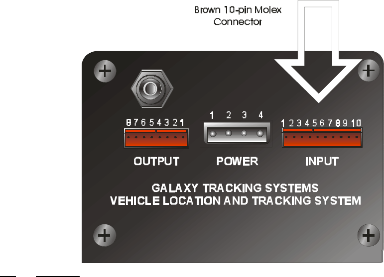
7 VTU Connectors and Connections
Figure 3 VTU INPUT PIN DEFINITIONS - 10 pin BROWN Molex Connector
Pin Function
10 DO NOT CONNECT, UNIT MAY BE DAMAGED BY ANY CONNECTION TO THIS PIN
9 Ground
8 DO NOT CONNECT, UNIT MAY BE DAMAGED BY ANY CONNECTION TO THIS PIN
7 DO NOT CONNECT, UNIT MAY BE DAMAGED BY ANY CONNECTION TO THIS PIN
6 DO NOT CONNECT, UNIT MAY BE DAMAGED BY ANY CONNECTION TO THIS PIN
5 NO CONNECTION
4 Input, Alarm Discrete--connect to ground (pin 9) to activate
3 Input, Unauthorized Movement Discrete--connect to ground (pin 9) to activate
2 Input, Roadside Assistance request Discrete--connect to ground (pin 9) to activate
1 Input, SOS Input Discrete--connect to ground (pin 9) to activate
Galaxy Tracking Systems, L.L.C. VTU User’s Guide
8
Use or disclosure of data contained on this sheet is subject to the restriction on the title page of this report.
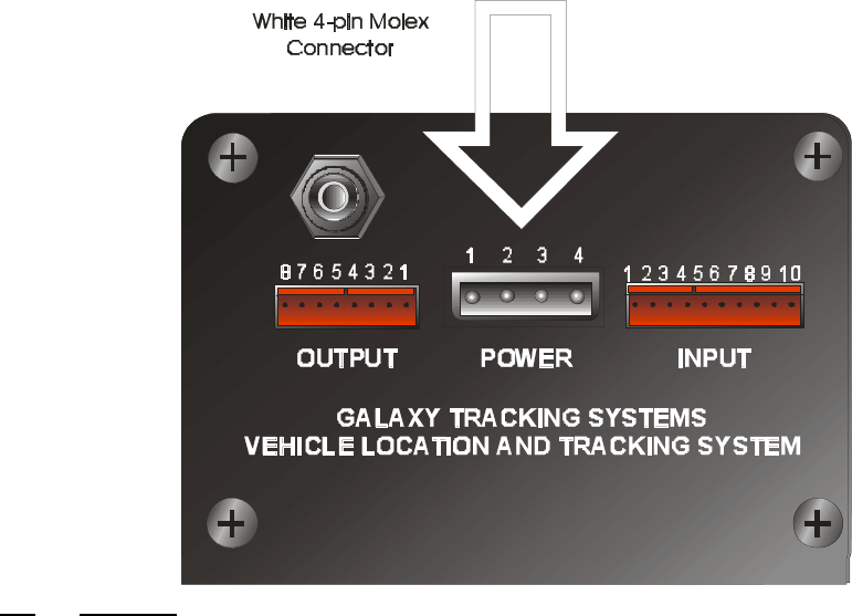
Figure 4 VTU POWER CONNECTOR PIN DEFINITIONS - 4 pin WHITE Molex
Connector
Pin Function
1 Chassis Ground
2 VCC +12V
3 No Connection
4 Ignition Sense-- +12V if engine on/ 0 V if off
Galaxy Tracking Systems, L.L.C. VTU User’s Guide
9
Use or disclosure of data contained on this sheet is subject to the restriction on the title page of this report.
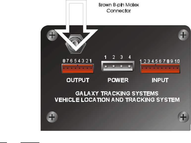
Figure 5 VTU OUTPUT PIN DEFINITIONS - 8 pin BROWN Molex Connector
Pin Function
1 Power / Transmit LED (Connect anode of LED to this pin, cathode to pin 9 of the 10 pin Molex or other
ground point) Illuminates when unit is powered, blinks off during transmit.
2 Unauthorized Movement Indicator LED (Connect cathode of LED to this pin, anode through 500 ohm
resistor to 12V)
3 Roadside Assistance request Indicator LED (Connect cathode of LED to this pin, anode through 500 ohm
resistor to 12V)
4 SOS Indicator LED (Connect cathode of LED to this pin, anode through 500 ohm resistor to 12V)
5 Engine Disable Relay control—Inactive: 0V. Active: 5V to shut off engine. WARNING, This output can
only provide 20 ma of current. Drawing more than 20 ma at this pin will destroy the device. There MUST
be a current amplification device at this output to drive the relay.
6 Signal Light Relay control—Inactive: 0V. Active: oscillates to 0 to 5V to flash signal lights. WARNING,
This output can only provide 20 ma of current. Drawing more than 20 ma at this pin will destroy the
device. There MUST be a current amplification device at this output to drive the relay.
7 Horn Relay control—Inactive: 0V. Active: oscillates 0 to 5V to honk horn. WARNING, This output can
only provide 20 ma of current. Drawing more than 20 ma at this pin will destroy the device. There MUST
be a current amplification device at this output to drive the relay.
8 Headlights Relay control—Inactive: 0V. Active: oscillates 0 to 5V to flash headlights. WARNING, This
output can only provide 20 ma of current. Drawing more than 20 ma at this pin will destroy the device.
There MUST be a current amplification device at this output to drive the relay.
The VTU is equipped with a total of four inputs (J2) and eight outputs (J1).
7.1 Inputs
Three of the inputs (pins 1-3 on J2) interface to the Switch Box option. The functions
currently served by these connections are SOS, request for roadside assistance and
arming of the unauthorized movement sensor. A momentary contact switch is provided
Galaxy Tracking Systems, L.L.C. VTU User’s Guide
10
Use or disclosure of data contained on this sheet is subject to the restriction on the title page of this report.
on the Switch Box for each of the three inputs. When pressed, two of the switches
issue silent alarms (SOS, Assistance) and the third toggles the unauthorized movement
sensor between the armed and disarmed states. The remaining input is used to sense
activation of the vehicle alarm system (if present).
7.2 Outputs
Each of the three Switch Box switches have an associated status LED output (pins 5-7
on J1). When one of the silent alarm switches is pressed, the corresponding LED will
flash at a 1 Hz rate to indicate an alarm has been sent to the command center. When
the alarm is acknowledged, the LED lights continuously. The LED can only be
extinguished (and the alarm cleared) from the command center. The third LED is lit
when the unauthorized movement sensor is armed.
The fourth output (pin 8) drives an LED that indicates VTU power and blinks off
whenever the VTU transmits.
The remaining four outputs (pins 4, 5, 6 and 7) can drive small loads (<20mA) and must
be interfaced to real world circuits through high current drivers (MOSFETS) or relays.
These outputs are dedicated to the control of external devices such as vehicle
accessories, horns, etc.
7.3 Power
7.4 Antennas
Galaxy Tracking Systems, L.L.C. VTU User’s Guide
11
Use or disclosure of data contained on this sheet is subject to the restriction on the title page of this report.
8 VTU Operations
8.1 VTU Startup
The VTU initializes first time power is applied after installation. Most importantly, the
GPS receiver must find and track satellites, compute its position and synchronize to
GPS time. A clear view of the sky and the GPS satellite constellation is required to do
this. If the vehicle is parked in a garage or is shaded from the sky, it should be moved
to a location with an unobstructed view of the sky. The vehicle SHOULD REMAIN
STATIONARY until the GPS receiver has had time to initialize (30 minutes or less).
It is absolutely imperative that GPS initialize properly. All VTU and CBU
communications are synchronized to GPS time. An unsynchronized VTU may transmit
within some other VTU’s time slot (in which case both VTUs seem to disappear) or may
not transmit at all.
To verify that the VTU is ready for use, a series of commands are issued form the
command center. A number of ONE-SHOT commands are transmitted first. A ONE
SHOT requests a single response from the VTU no matter what its operating mode.
Any response from the VTU verifies the communication link and that VTU time keeping
via GPS has been established.
Next the VTU is commanded to IN SERVICE mode. Proper initialization of the VTU is
indicated when the correct time, GPS tracking status and position are returned to the
command center in the IN SERVICE response. If the status is not correct, additional
ONE-SHOT commands are transmitted to the VTU until the responses (IN SERVICE
messages) indicate that initialization is complete. At this point the VTU is ready for use.
Once the VTU has been initialized the first time, it will be able to reinitialize within a
minute unless it has been disconnected from vehicle battery power for a long period of
time (greater than a week).
8.2 VTU Operating Modes
The VTU operates in one of two modes, IN SERVICE or OUT OF SERVICE. In either
mode, the VTU receives commands over the UHF radio link from the command center.
The VTU confirms each command by responding with either an IN SERVICE or OUT
OF SERVICE message.
Commanded settings and status are maintained through power outages.
8.2.1 OUT OF SERVICE Operating Mode
The VTU is factory configured to begin life in the OUT OF SERVICE operating mode.
OUT OF SERVICE is a standby mode that is also used to verify unit communications.

Galaxy Tracking Systems, L.L.C. VTU User’s Guide
12
Use or disclosure of data contained on this sheet is subject to the restriction on the title page of this report.
While in this mode, the VTU will transmit an OUT OF SERVICE response to all
commands except the IN SERVICE command.
When OUT OF SERVICE, all in-vehicle alarms are disabled, (see SELF-ACTIVATION).
8.2.1.1 OUT OF SERVICE Operating Mode Commands
The commands available with OUT OF SERVICE follow.
IN SERVICE Command
Upon receipt of an IN SERVICE command, the VTU will change operating mode to IN
SERVICE and transmit an IN SERVICE message to report the change in mode. The
VTU is set operational by this command and can begin to report position, time, status
and on-board alarms.
8.2.2 IN SERVICE Operating Mode
When commanded IN SERVICE, the VTU will respond with a single IN SERVICE
message at the exact time indicated in the command packet. While IN SERVICE, the
VTU transmits an IN SERVICE message in response to all commands. The VTU will
also transmit an IN SERVICE message in response to alarms activated by the vehicle
operator (e.g., SOS) or events (e.g., unauthorized movement).
8.2.2.1 IN SERVICE Operating Mode Commands
The commands available with IN SERVICE follow.
OUT OF SERVICE
The VTU will change operating mode to OUT OF SERVICE and transmit an OUT OF
SERVICE message to report the change in mode. On-board alarms are disabled. All
subsequent commands (except IN SERVICE) are answered with an OUT OF SERVICE
message.
ONE SHOT
The one-shot command is a request for a single position / status report. The VTU
responds with a single IN SERVICE message containing current status, position, speed
and time.
ACTIVATE TRACKING
The ACTIVATE TRACKING command causes the VTU to begin regular position
reporting. The rate and the exact moment at which the VTU reports and the frequency
on which the report is transmitted are all contained in the command. Tracking mode is
used to monitor vehicle movements and status in real-time and to vector pursuit
vehicles to intercept points.
DEACTIVATE TRACKING
Position reporting ceases when DEACTIVATE TRACKING is commanded. The VTU

Galaxy Tracking Systems, L.L.C. VTU User’s Guide
13
Use or disclosure of data contained on this sheet is subject to the restriction on the title page of this report.
responds with one last IN SERVICE message to indicate the change in tracking status.
Commanding the VTU OUT OF SERVICE also stops tracking reports, however, in this
case, the VTU responds with a single OUT OF SERVICE message to report its change
in operating mode.
POLL REQUEST
The POLL REQUEST equivalent to issuing a ONE SHOT to every member a group
(fleet) of vehicles. Upon receipt of a POLL REQUEST each VTU will compare the
transmitted poll information to poll classes defined internally. If there is a match, the
VTU will transmit an IN SERVICE message at the frequency and in the time slot
specified in the matching poll class. Poll classes are factory configured to allow low
priority status reporting for large groups of related vehicles.
Poll responses are low priority. If the VTU is responding to a command or a self-
activation the poll request is ignored. A scheduled poll response is automatically
canceled if the VTU receives a command packet or self-activates. Polls do not extend
beyond the end of the 30-second cycle in which the poll was requested. If the VTU
schedules a poll response, it will ignore any new poll packets until the scheduled poll
response completes.
SELF ACTIVATION (SOS)
A vehicle (VTU) does not report its position on a regular basis until it is commanded to
ACTIVATE by the command center. In emergency situations, however, the VTU can
request to begin regular position reporting in order to be tracked by “SELF
ACTIVATING”.
The conditions that can result in SELF-ACTIVATIONS are SOS, request for roadside
assistance, unauthorized movement and vehicle alarm. SOS and the roadside
assistance requests are initiated when the operator depresses a switch (if equipped
with the switch box option). If the operator has armed the VTU motion sensor (included
in the switch box option), movement of the vehicle beyond a few hundred feet or at
speeds in excess of 20 KPH will trigger a SELF-ACTIVATION.
If the vehicle has an alarm system with an appropriate output signal, it can be
connected to the VTU. Triggering the vehicle alarm will then also generate a SELF-
ACTIVATION.
SELF ACTIVATION ACKNOWLEDGEMENT
Once a SELF-ACTIVATION has occurred, the corresponding status LED on the switch
box will blink until the SELF-ACTIVATION has been acknowledged by the command
center, at which point the LED will glow steadily.
RESET ALARMS
Galaxy Tracking Systems, L.L.C. VTU User’s Guide
14
Use or disclosure of data contained on this sheet is subject to the restriction on the title page of this report.
The SELF-ACTIVATION condition can only be cleared from the command center after
the situation causing it has been addressed. Clearing the SELF-ACTIVATION
extinguishes the LED. The reset command clears all Self Activations currently in
process in the VTU, including those that have not been acknowledged.