Gallagher Group C19753X Prox Reader Mifare (Teardrop) User Manual Prox Mifare Series Teardrop
Gallagher Group Ltd Prox Reader Mifare (Teardrop) Prox Mifare Series Teardrop
UserManual.wiki
>
Gallagher Group
>
C19753X User Manual
Users Manual
Navigation menu
Upload a User Manual
Namespaces
Wiki Guide
HTML
PDF
Info
Views
User Manual
Discussion / Help
Navigation

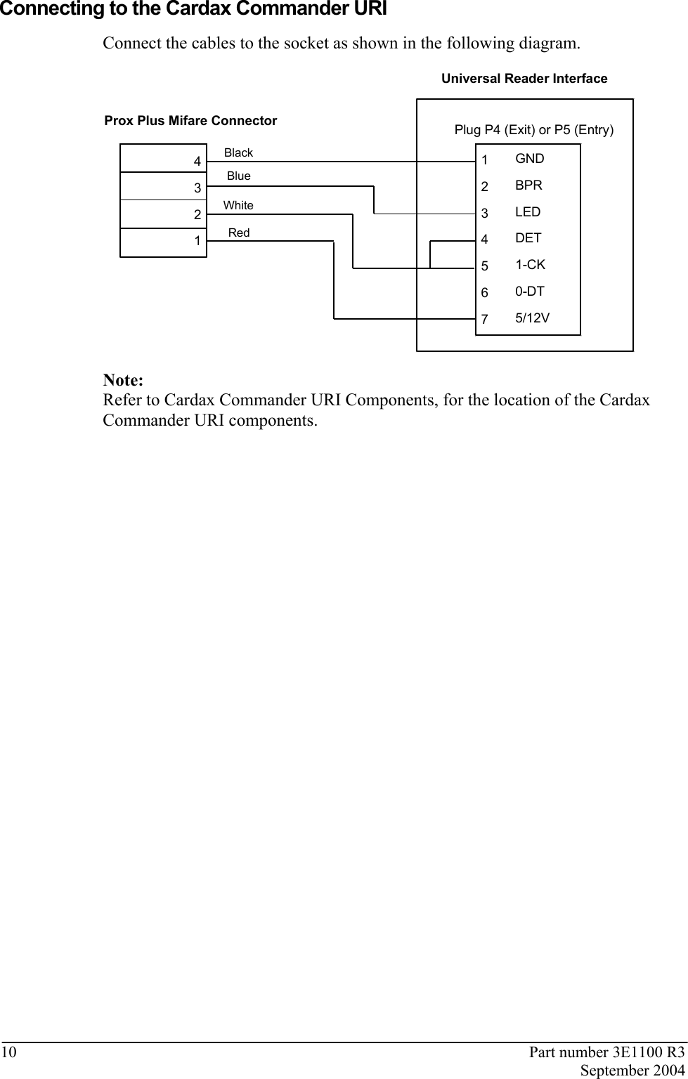
![Part number 3E1100 R3 9 September 2004 Connecting to the Cardax FT URI Connect the cables to the socket as shown: Prox Plus Mifare Connector4321GNDOUTPUTSOUTPUTSDETCOMMSCOMMS5/12VPlug P1 or P2Cardax FT Universal Reader InterfaceRedWhiteBlueBlack Connect the Prox Mifare Series (Teardrop) reader connector to either the P1 or P2 plug on the Cardax FT URI. Refer to the Cardax FT URI component layout diagram, next, for the location of the plugs. Q31D18U19T1R7R50R55R52R51R53R54JP2D13D23D24D1D2D3D4D6D5D11D10D25D20D19D17D15Q7Q2D12D16D14Q30Q2992101P8JP1SW1EQ26Q27COMMNC NOCOILRLY2COMMNC NOCOILD28D27D26R80R79R95R96R81R94D21Q28D22Q41(c)1999 PEC(New Zealand) LtdREV[A][B][C]22825V2 Assy 228265V 12VP4Balanced Inputspin 1 = Input1pin 2 = Input 2pin 3 = Input 3pin 4 = Input 4pin 5 = Input 5pin 6 = Input 6pin 7 = GroundP7Relay Outputspin 1 = R1 Normally closedpin 2 = R1 Normally openpin 3 = R1 Commonpin 4 = R2 Normally closedpin 5 = R2 Normally openpin 6 = R2 Commonpin 7 = GroundP5Power & Commspins 1 & 2 = RS485pin 3 = 13.6 V ± 15%pin 4 = 0VSW1Unit addressSet unit numberP8Diagnostic portP613.6 V ± 15%outpin 1 = 13.6 V ± 15%pin 2 = Ground 3A fusedP3Keypadpin 1 = Row1pin 2 = Row 2pin 3 = Row 3pin 4 = Row 4pin 5 = Column1pin 6 = Column2pin 7 = Column3pin 8 = GroundP2Non-CardaxFTReader 2pin 1 = 5/12 V powerpin 2 = DataApin 3 = DataBpin 4 = Card detectpin 5 = LED outputpin 6 = Beeper outputpin 7 = GroundP1Non-CardaxFTReader 1pin 1 = 5/12 V powerpin 2 = DataApin 3 = DataBpin 4 = Card detectpin 5 = LED outputpin 6 = Beeper outputpin 7 = GroundF113.6 V Input FuseRating = 500mAF213.6 V Output FuseRating = 3AD17 and D21Relay state indicatorsLED on = EnergisedLED off = De-energisedD18Run LEDD10Comms LEDflashing = communicating withFT ControllerJP1Reader Voltage select= 5V (200mA total)= 12V (1A total)P1P2](https://usermanual.wiki/Gallagher-Group/C19753X/User-Guide-471897-Page-9.png)