Gallagher Group C30022X Prox Readers T11 Mifare and T12 Mifare User Manual
Gallagher Group Ltd Prox Readers T11 Mifare and T12 Mifare Users Manual
Users Manual
R5 | Part Number: 3E2512 | 1
Installation Note | Gallagher T12 Reader
Installation Note
Gallagher T12 Reader
The Gallagher T12 Reader
The Gallagher T12 Reader is a smart card proximity reader. It can be installed
as either an entry reader or exit reader. It can be mounted on a BS 4662 British
Standard square flush box.
The reader can read Mifare DESFire EV1, Mifare Plus and Mifare Classic cards.
The Multi Tech variant can also read 125Khz cards.
Gallagher T12 Multi Tech Readers only: Using dual technology 125/Mifare
cards with Gallagher T12 Multi Tech Readers may cause both card technologies
to be read, resulting in double card badges and unusual reader feedback.
Gallagher strongly recommends against using dual technology 125/Mifare
cards with Gallagher Multi Tech Readers for sites running pre-Command Centre
v7.00 software (due for release 2nd half, 2011). From Command Centre
v7.00, a site may specify which technology a Multi Tech reader should read
off a dual technology card.
This equipment contains components that can be damaged by electrostatic
discharge. Ensure both you and the equipment are earthed before beginning
any servicing.

2 | Part Number: 3E2512 | R5
Installation Note | Gallagher T12 Reader
The reader sends information to the Cardax FT Controller and acts upon information
sent from the Cardax FT Controller. The reader itself does not make any access
decisions.
The Gallagher T12 Reader uses the “Cardax IV Reader” communications protocol
to communicate with the Cardax FT Controller.
Before you begin
Shipment Contents
Check the shipment contains the following items:
1 x Gallagher T12 Reader facia assembly•
1 x Gallagher T12 Reader base•
1 x M3 Torx Post Security screw•
2 x M3.5 Phillips drive fixing screws•
4 x 25mm No.6 self tapping, pan head, Phillips drive fixing screws•
4 x 40mm No.6 self tapping, pan head, Phillips drive fixing screws•
Power Supply
The Gallagher T12 Reader is designed to operate over a supply voltage range of
9 - 16Vdc measured at the reader terminals. The operating current draw is dependant
on the supply voltage at the reader. For the Standard variant at 12Vdc the current
draw is 89mA (standby). During card read, beeper and LED activity, the current will
momentarily reach 124mA (peak). For the Multi Tech variant at 12Vdc the current
draw is 88mA (standby) and will momentarily reach 140mA (peak).
The power source should be linear or a good quality switched-mode power supply. The
performance of the reader may be affected by a low quality, noisy power supply.
Cabling
The Gallagher T12 Reader requires a minimum cable size of 4 core 24 AWG
(0.2mm2) stranded security cable. This cable allows the transmission of data (2 wires)
and power (2 wires). When using a single cable to carry both power supply and
data, both the power supply voltage drop and data requirements must be considered.
Although the reader is specified to operate at 9Vdc, for good engineering design it
is recommended that the voltage at the reader should be approximately 12Vdc.
Examples of approved cables for connecting a single Gallagher T12 Reader to a
Controller and power supply, showing maximum cable lengths for each type of cable
and the associated circuits are:
R5 | Part Number: 3E2512 | 3
Installation Note | Gallagher T12 Reader
Manufacturer
reference Cable format*
Combined
power and data
in a single cable
Data only in a
single cable
CAT5E 4 twisted pair
Each 2 x 0.2mm2 (24 AWG)
100m (330ft) 300m (1000ft)
SEC472 4 x 0.2mm2
Not twisted pairs (24 AWG)
100m (330ft) 250m (800ft)
SEC4142 4 x 0.4mm2
Not twisted pairs (21 AWG)
150m (500ft) 150m (500ft)
BELDEN 8723 2 twisted pair
Each 2 x 0.4mm2 (22 AWG)
100m (330ft) 150m (500ft)
BELDEN 9842 2 twisted pair
Each 2 x 0.2mm2 (24 AWG)
100m (330ft) 200m (650ft)
* The matching of wire sizes to equivalent wire gauges are only approximate.
Note: Grounding shielded cable may reduce the obtainable cable length by 25%
to 30%.
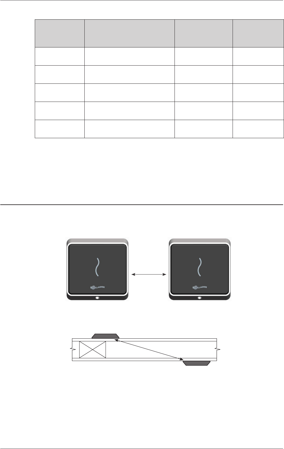
Distance between Proximity Readers
The distance separating any two proximity readers must not be less than 200mm
(8 inches) in all directions.
200mm
When mounting a proximity reader on an internal wall, check that any reader fixed
to the other side of the wall is not less than 200mm (8 inches) away.
200mm
4 | Part Number: 3E2512 | R5
Installation Note | Gallagher T12 Reader
Installation
The Gallagher T12 Reader is designed to be mounted on a standard British electrical
flush box, or any solid flat surface. However installation on metal surfaces, particularly
those with a large surface area will reduce read range. The extent to which the range
is reduced will depend upon the type of metal used.
The recommended mounting height for the reader is 1.1m (3.6ft) from the floor level
to the centre of the reader device. However this may vary in some countries and you
should check local regulations for variations to this height.
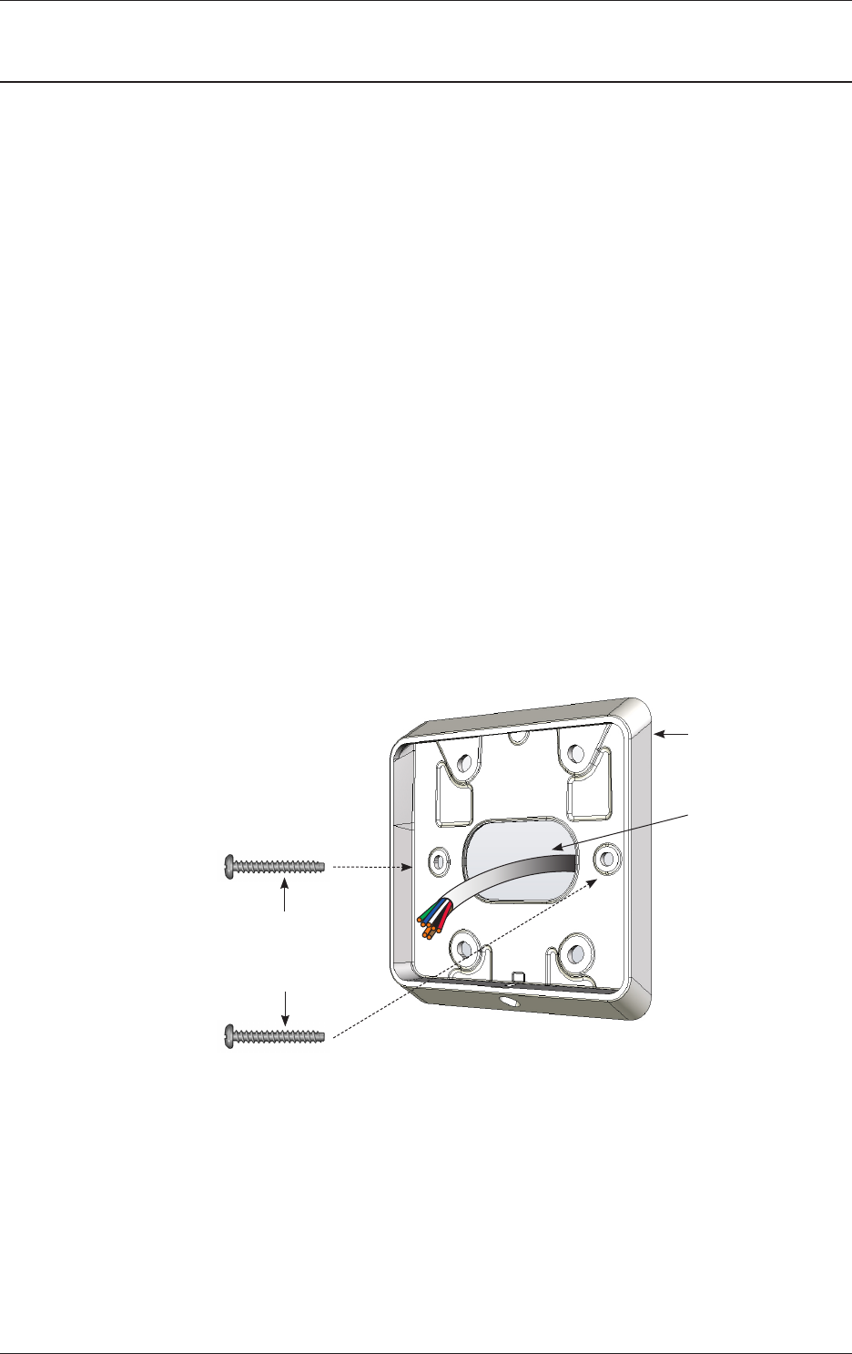
Ensure the building cable has been run out through the flush box.1.
If you are not mounting to a flush box, use the drill template at the back of this
installation note as a guide, to drill all five holes. Drill the 13mm (1/2 inch)
diameter centre hole (this is the centre hole for which the building cable will
exit the mounting surface) and the four fixing holes.
Run the building cabling through the reader base.2.
Secure the base to the flush box using the two M3.5 screws provided. It is 3.
important the base of the reader is flush with and tight against the mounting
surface.
If you are not mounting to a flush box, secure the base to the mounting surface
using the four fixing screws provided.
Base
Building
cable
M3.5 screw
M3.5 screw
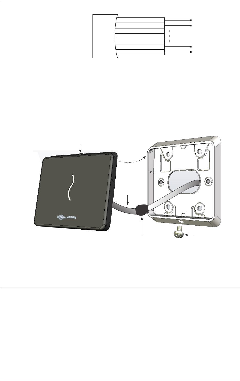
Connect the reader tail extending from the facia assembly to the building cable. 4.
Connect the wires shown below.
Note: Do not cut the ‘Reserved’ wires, as these may be used for future functions.
R5 | Part Number: 3E2512 | 5
Installation Note | Gallagher T12 Reader
Positive Red
Negative Black
Reserved Orange
Reserved Green
Reserved Brown
CDXIV TX White
CDXIV RX Blue
Cardax IV Reader
Fit the facia assembly into the base by clipping the small lip, into the top of 5.
the base and holding the top, press the bottom of the facia assembly down
into the base.
Insert the M3 Torx Post Security screw (using a T10 Torx Post Security screwdriver) 6.
through the hole at the bottom of the base to secure the facia assembly.
Note: The recommended torque for the security screw is 0.7Nm (0.5 lb/ft). It
is important not to exceed the maximum torque of 1.5Nm (1.1 lb/ft).
Facia
Reader tail
Connection Fit screw to secure
facia to base
Removal of the facia assembly is a simple reversal of these steps.7.
Connections
A Gallagher T12 Reader can connect to one of the following devices using the
“Cardax IV Reader” communications protocol:
Cardax FT Reader Module (for the Controller 6000)•
Cardax FT GBUS Universal Reader Interface (Cardax FT GBUS URI)•
Cardax FT Controller 3000-4R or 3000-8R•
Cardax FT Universal Reader Interface (Cardax FT URI)•
Cardax FT Reader I/O Interface•
6 | Part Number: 3E2512 | R5
Installation Note | Gallagher T12 Reader
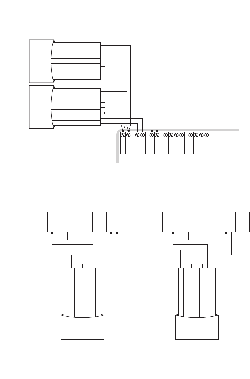
Connecting to the Cardax FT Reader Module (for the Controller 6000)
Connect the wires to the sockets as shown:
-
+
R1 Out
R1 In
C
1
2
3
C
4
5
6
R2 Out
R2 In
Cardax FT Reader Module
Positive Red
Negative Black
Reserved Orange
Reserved Green
Reserved Brown
CDXIV TX White
CDXIV RX Blue
Cardax IV Reader 2
Positive Red
Negative Black
Reserved Orange
Reserved Green
Reserved Brown
CDXIV TX White
CDXIV RX Blue
Cardax IV Reader 1
Connecting to the Cardax FT GBUS Universal Reader Interface
Connect the wires to the sockets as shown in either of the following diagrams:
RLY 2 COM
RLY 2 NO
RLY 2 NC
DATA 0
DATA 1
OUT 1
OUT 2
COM A
COM B
TAMPER
GND
VOUT
GND
VIN
GND
Pin 15 Reader Top Row
Pin 1
Cardax FT GBUS URI
Positive Red
Negative Black
Reserved Orange
Reserved Green
Reserved Brown
CDXIV TX White
CDXIV RX Blue
Cardax IV Reader
RLY 2 COM
RLY 2 NO
RLY 2 NC
DATA 0
DATA 1
OUT 1
OUT 2
COM A
COM B
TAMPER
GND
VOUT
GND
VIN
GND
Pin 15 Reader Top Row
Pin 1
Cardax FT GBUS URI
Positive Red
Negative Black
Reserved Orange
Reserved Green
Reserved Brown
CDXIV TX White
CDXIV RX Blue
Cardax IV Reader
R5 | Part Number: 3E2512 | 7
Installation Note | Gallagher T12 Reader
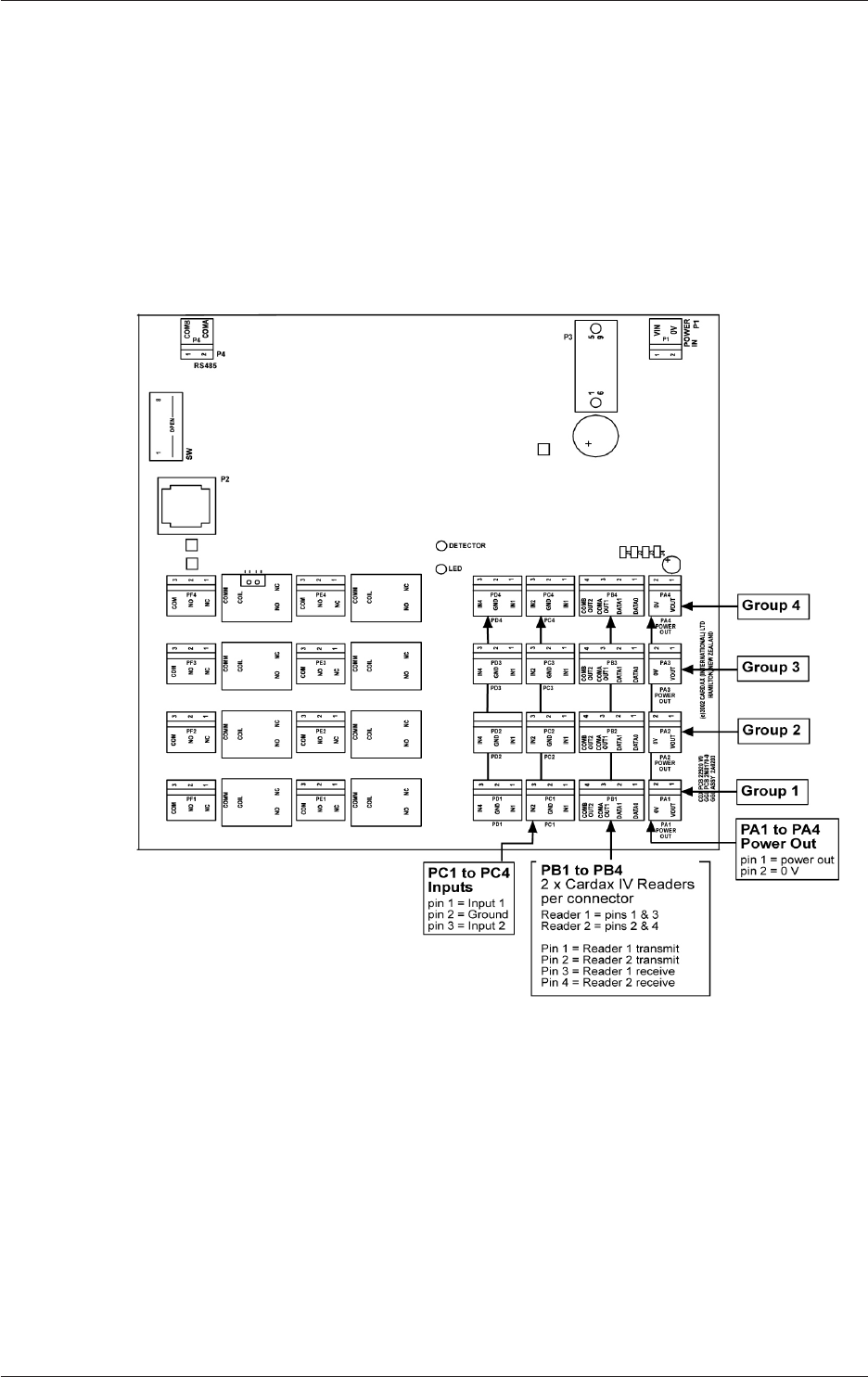
Connecting to the Cardax FT Controller 3000-4R or 3000-8R
The ports to which the Gallagher T12 Reader can connect are set up as groups, as
follows:
Two groups (numbered 1 and 2) on the Controller 3000-4R, and•
Four groups (numbered 1 to 4) on the Controller 3000-8R•
Each group provides connection for two Gallagher T12 Readers. Refer to the following
diagram for the location of the ports on the Cardax FT Controller 3000-8R.
8 | Part Number: 3E2512 | R5
Installation Note | Gallagher T12 Reader
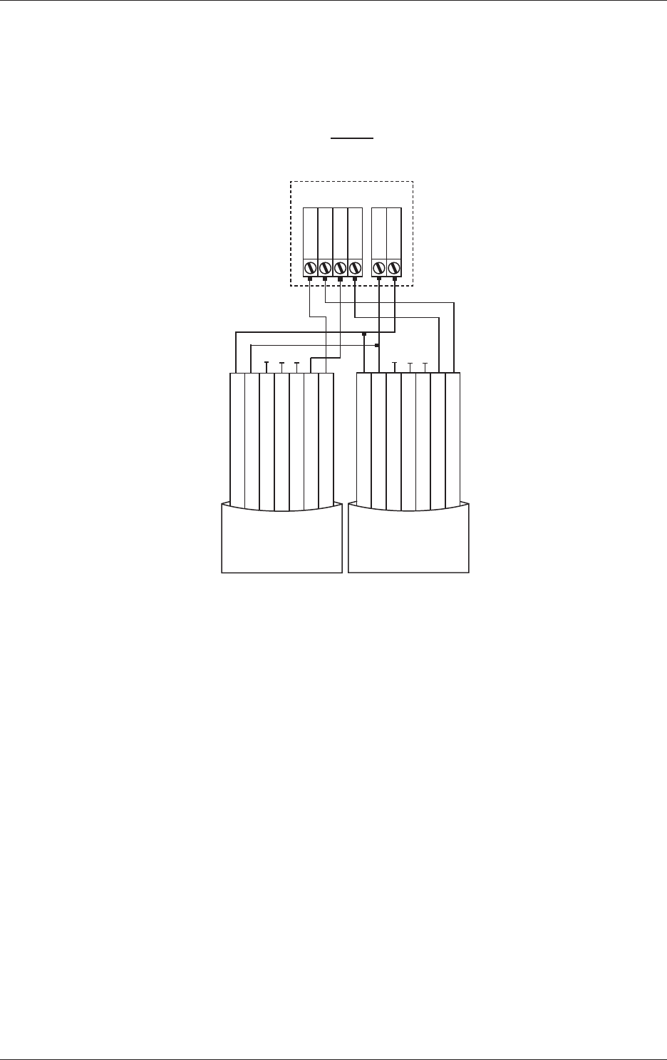
Make the connections from the Gallagher T12 Reader to either the Cardax FT
Controller 3000-4R or 3000-8R as shown:
PB1 and PA1... to... PB2 and PA2 (3000-4R)
PB4 and PA4 (3000-8R)
Cardax FT Controller 3000-4R or 3000-8R
Group
1 V OUT
2 0 V
1 DATA 0
2 DATA 1
3 OUT 1
4 OUT 2
PB PA
Positive Red
Negative Black
Reserved Orange
Reserved Green
Reserved Brown
CDXIV TX White
CDXIV RX Blue
Cardax IV Reader
Positive Red
Negative Black
Reserved Orange
Reserved Green
Reserved Brown
CDXIV TX White
CDXIV RX Blue
Cardax IV Reader
Note: Within each group, you cannot mix Cardax IV readers with Wiegand Readers.
This is because connecting one Wiegand reader requires all four pins on plug PB. For
example, if you connect a Cardax IV reader to Port 1 of Group 1, Port 2 of Group
1 can only connect to another Cardax IV reader.
R5 | Part Number: 3E2512 | 9
Installation Note | Gallagher T12 Reader
Technical Specications
Technical Specications
Routine maintenance: Not applicable for this reader
Cleaning: This reader should only be cleaned with a clean, lint
free, damp cloth
Power required: Voltage: 9Vdc - 16Vdc
Current (at 12Vdc): 89mA (standby) Standard variant
124mA (peak) Standard variant
88mA (standby) Multi Tech variant
140mA (peak) Multi Tech variant
Environmental: Temperature Range: -30°C to +70°C
Note: Direct sunlight may increase the internal reader
temperature above the ambient temperature level.
Humidity: 95% non-condensing
Environmental Protection: IP68
Impact Rating: IK07
Approvals and Standards
This product complies with the environmental regulations for the
Restriction of Hazardous Substances in electrical and electronic
equipment (RoHS). The RoHS directive prohibits the use of
electronic equipment containing certain hazardous substances in
the European Union.
This symbol on the product or its packaging indicates that this
product must not be disposed of with other waste. Instead, it is
your responsibility to dispose of your waste equipment by handing
it over to a designated collection point for the recycling of waste
electrical and electronic equipment. The separate collection and
recycling of your waste equipment at the time of disposal will
help conserve natural resources and ensure that it is recycled in a
manner that protects human health and the environment. For more
information about where you can drop off your waste equipment
for recycling, please contact your local city recycling office or the
dealer from whom you purchased the product.
ACN 002 132 943

10 | Part Number: 3E2512 | R5
Installation Note | Gallagher T12 Reader
FCC This device complies with part 15 of the FCC Rules. Operation
is subject to the following two conditions: (1) This device may
not cause harmful interference, and (2) this device must accept
any interference received, including interference that may cause
undesired operation.
Note: Changes or modifications not expressly approved by
Gallagher Group Limited could void the user’s authority to operate
this equipment.
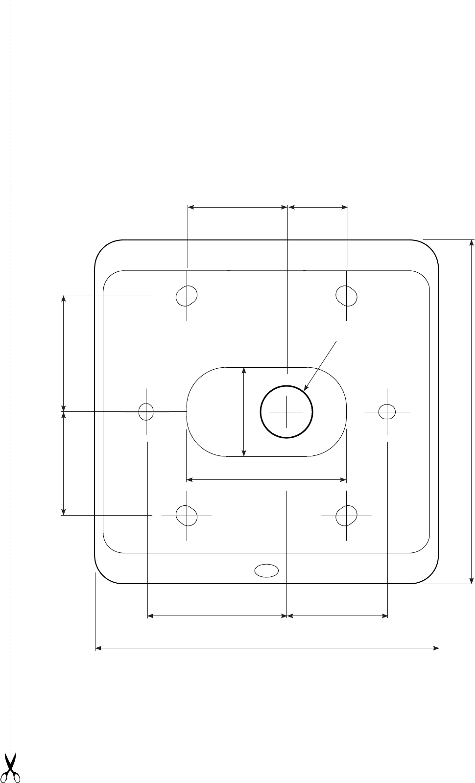
Drill Template
35mm (1.38 inches)
26mm (1 inch) 29mm (1.41 inches)
86mm (3.39 inches)
13mm (1/2 inch)
diameter
hole for cable
86mm (3.39 inches)
25mm (1 inch)
25mm (1 inch)
15mm
22.3mm
(0.88 inches)
40mm (1.57 inches)
(0.59 inches)