Gallagher Group C30044XA Prox Readers T11 Multi Tech, T11 Multi Tech PIV and T12 Multi Tech User Manual
Gallagher Group Ltd Prox Readers T11 Multi Tech, T11 Multi Tech PIV and T12 Multi Tech Users Manual
Contents
- 1. Users Mnual
- 2. Users Manual 2
- 3. Users Manual
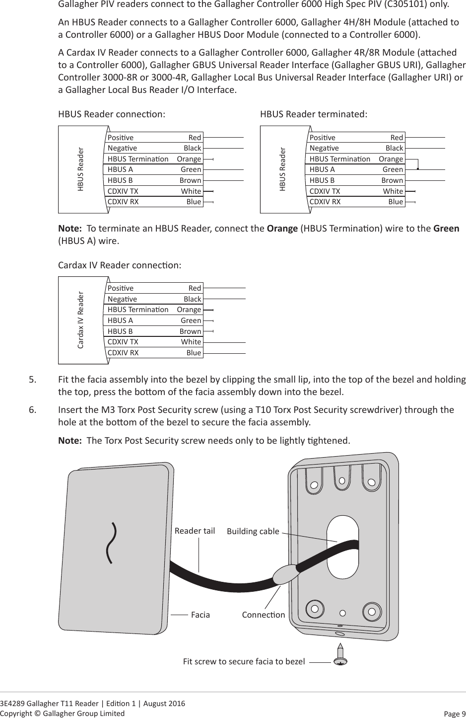
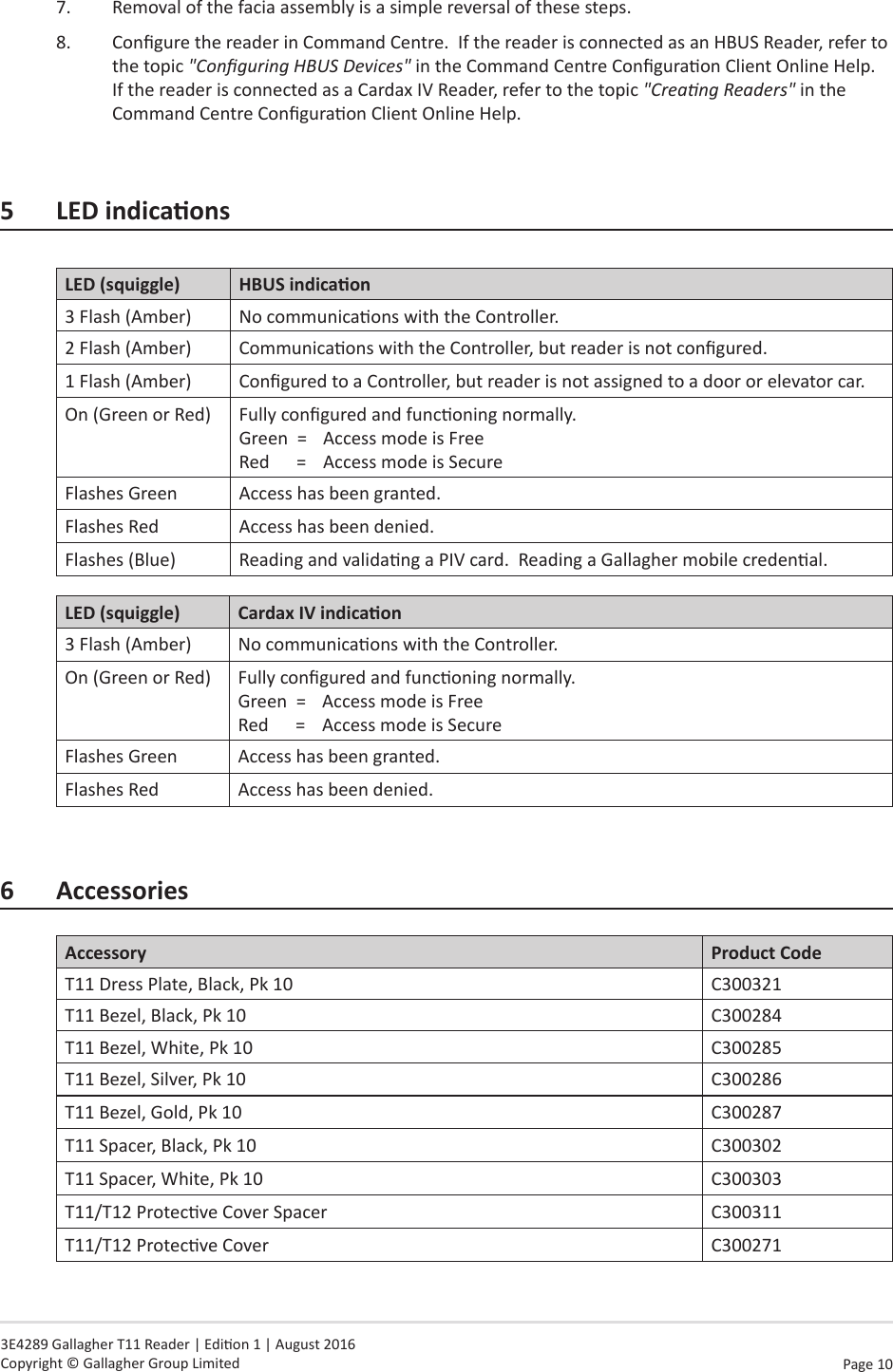
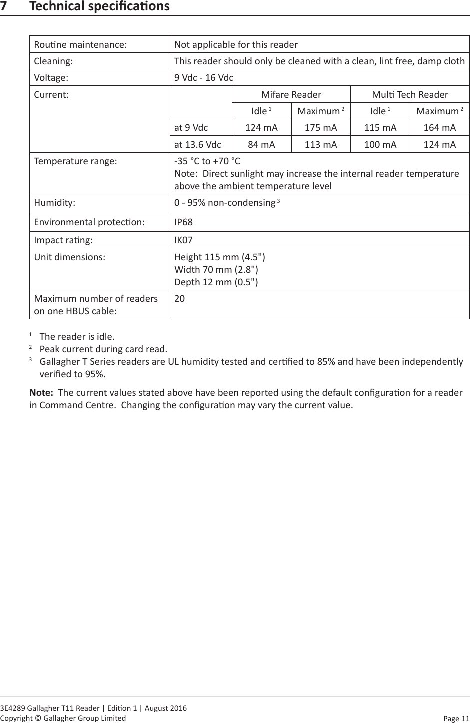
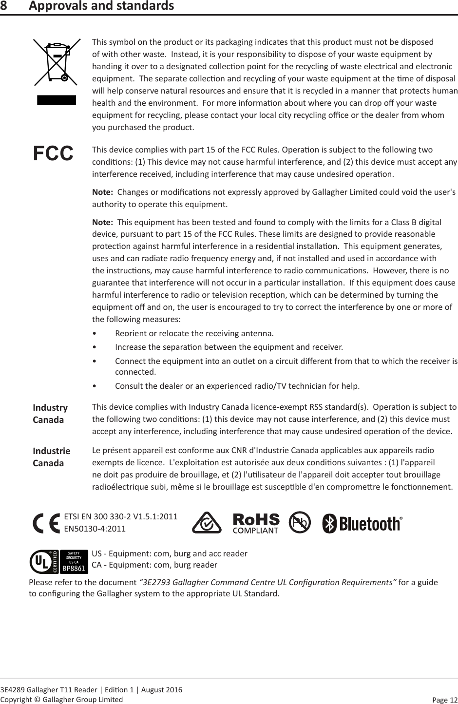
Users Manual