Garland XG362S L 4526884 Sonic Gas Xpress Grill Rev 4 User Manual To The Ca9db746 A575 46fe B6c2 B558367c8085
User Manual: Garland XG362S-L to the manual
Open the PDF directly: View PDF ![]() .
.
Page Count: 42
Part # 4526884 Rev 4 (10/08/10)
Users are cautioned that maintenance and repairs must be performed by a Garland authorized service agent
using genuine Garland replacement parts. Garland will have no obligation with respect to any product that has been
improperly installed, adjusted, operated or not maintained in accordance with national and local codes or installation
instructions provided with the product, or any product that has its serial number defaced, obliterated or removed,
or which has been modied or repaired using unauthorized parts or by unauthorized service agents.
For a list of authorized service agents, please refer to the Garland web site at http://www.garland-group.com.
The information contained herein, (including design and parts specications), may be superseded and is subject
to change without notice.
© 2010 The Garland Group
FOR YOUR SAFETY:
DO NOT STORE OR USE GASOLINE
OR OTHER FLAMMABLE VAPORS OR
LIQUIDS IN THE VICINITY OF THIS OR ANY OTHER
APPLIANCE
WARNING:
IMPROPER INSTALLATION, ADJUSTMENT,
ALTERATION, SERVICE OR MAINTENANCE CAN
CAUSE PROPERTY DAMAGE, INJURY, OR DEATH.
READ THE INSTALLATION,
OPERATING AND MAINTENANCE
INSTRUCTIONS THOROUGHLY
BEFORE INSTALLING OR
SERVICING THIS EQUIPMENT
PLEASE READ ALL SECTIONS OF THIS MANUAL AND
RETAIN FOR FUTURE REFERENCE.
THIS PRODUCT HAS BEEN CERTIFIED AS COMMERCIAL
COOKING EQUIPMENT AND MUST BE INSTALLED BY
PROFESSIONAL PERSONNEL AS SPECIFIED.
IN THE COMMONWEALTH OF MASSACHUSETTS
THIS PRODUCT MUST BE INSTALLED BY A LICENSED
PLUMBER OR GAS FITTER.
For Your Safety:
Post in a prominent location, instructions to be
followed in the event the user smells gas. This
information shall be obtained by consulting your local
gas supplier.
INSTALLATION
& OPERATING
INSTRUCTIONS
GAS & ELECTRIC XPRESS GRILLS
FOR SONIC
MODEL NUMBERS:
XG36S, XG362S-L, XE36S, XE362S-2L
GARLAND COMMERCIAL RANGES, LTD.
1177 Kamato Road, Mississauga, Ontario L4W 1X4
CANADA
Phone: 905-624-0260
Fax: 905-624-5669
* Energy Star only applies to the gas grill model XG36

Part # 4526884 Rev 4 (10/08/10)Page 2
IMPORTANT INFORMATION
WARNING:
This product contains chemicals known to the State of California to cause cancer and/or birth
defects or other reproductive harm. Installation and servicing of this product could expose you
to airborne particles of glass wool/ceramic fibers. Inhalation of airborne particles of glass wool/
ceramic fibers is known to the State of California to cause cancer. Operation of this product could
expose you to carbon monoxide if not adjusted properly. Inhalation of carbon monoxide is known
to the State of California to cause birth defects or other reproductive harm.
Part # 4526884 Rev 4 (10/08/10) Page 3
PRODUCT INFORMATION
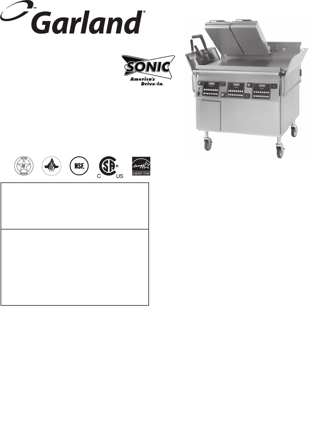
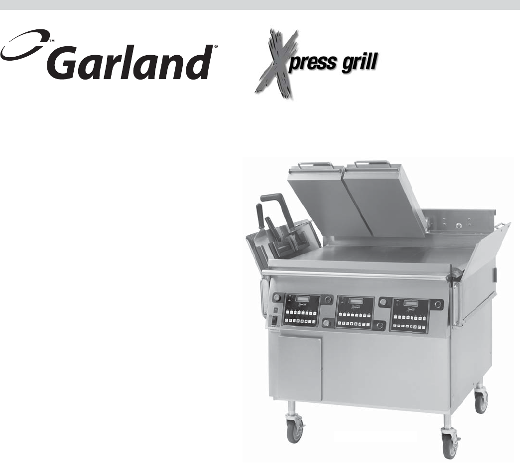
The Garland Xpress Grill provides a method for e cient two-sided cooking, while accommodating a variety of products. The
unit will also serve as a at grill, and meets all standards for safety, e ciency, and cleanliness.
Model XG362-L
Standard Features:
• Stainless steel front, top & sides
• 33,000 BTU/Hr input for each twelve-inch section
of griddle
• Built in pressure regulator, (one per twelve inch
section of griddle), and gas shut-o valve
• 3/4" thick, Carbon steel griddle plate, machine ground,
highly polished
• Swivel casters complete with front brakes (4)
• Die cast aluminum electric top heating elements
rated 208V or 240V
• Automatic lifting and lowering top heaters
• Towel bar with bun pan lip
• Two, 1.5 gal. (5.68 L), stainless steel grease containers
with utensil holders
• Separate programmable controller for each
twelve-inch section
• Multi-colored LED indicator lights to identify
operational mode
• Cord and plug power supply
• One year limited parts and labor warranty
(USA & Canada)
Model XG362S-L

Part # 4526884 Rev 4 (10/08/10)Page 4
IMPORTANT INFORMATION . . . . . . . . . . . . . . . . . . . . . . . . . . . . . . . . . . . . . . . . . . . . . . . . . . . . . 2
PRODUCT INFORMATION. . . . . . . . . . . . . . . . . . . . . . . . . . . . . . . . . . . . . . . . . . . . . . . . . . . . . . . . 3
Standard Features: . . . . . . . . . . . . . . . . . . . . . . . . . . . . . . . . . . . . . . . . . . . . . . . . . . . . . . . . . . . . . . . . . . . . . . . . . . . . . . . . 3
DIMENSIONS AND SPECIFICATIONS. . . . . . . . . . . . . . . . . . . . . . . . . . . . . . . . . . . . . . . . . . . . . . 6
INTRODUCTION . . . . . . . . . . . . . . . . . . . . . . . . . . . . . . . . . . . . . . . . . . . . . . . . . . . . . . . . . . . . . . . . 7
Warranty . . . . . . . . . . . . . . . . . . . . . . . . . . . . . . . . . . . . . . . . . . . . . . . . . . . . . . . . . . . . . . . . . . . . . . . . . . . . . . . . . . . . . . . . . 7
Shipping Damage Claim Procedure. . . . . . . . . . . . . . . . . . . . . . . . . . . . . . . . . . . . . . . . . . . . . . . . . . . . . . . . . . . . . . . . 7
SAFETY PRECAUTIONS . . . . . . . . . . . . . . . . . . . . . . . . . . . . . . . . . . . . . . . . . . . . . . . . . . . . . . . . . . 8
INSTALLATION. . . . . . . . . . . . . . . . . . . . . . . . . . . . . . . . . . . . . . . . . . . . . . . . . . . . . . . . . . . . . . . . . . 9
Rating Plate Location . . . . . . . . . . . . . . . . . . . . . . . . . . . . . . . . . . . . . . . . . . . . . . . . . . . . . . . . . . . . . . . . . . . . . . . . . . . . . 9
General Information . . . . . . . . . . . . . . . . . . . . . . . . . . . . . . . . . . . . . . . . . . . . . . . . . . . . . . . . . . . . . . . . . . . . . . . . . . . . . . 9
National Codes Requirements: . . . . . . . . . . . . . . . . . . . . . . . . . . . . . . . . . . . . . . . . . . . . . . . . . . . . . . . . . . . . . . . . . . . . 9
Gas Connections, and Pipe Sizing: . . . . . . . . . . . . . . . . . . . . . . . . . . . . . . . . . . . . . . . . . . . . . . . . . . . . . . . . . . . . . . . . . 9
Accessory Kit – Main Gas Inlet:. . . . . . . . . . . . . . . . . . . . . . . . . . . . . . . . . . . . . . . . . . . . . . . . . . . . . . . . . . . . . . . . . . . . 10
Accessory Kit – Electrical Supply Lines:. . . . . . . . . . . . . . . . . . . . . . . . . . . . . . . . . . . . . . . . . . . . . . . . . . . . . . . . . . . . 11
Electrical Connection Terminal Block Connection . . . . . . . . . . . . . . . . . . . . . . . . . . . . . . . . . . . . . . . . . . . . . . . . . 12
Grease Bucket: . . . . . . . . . . . . . . . . . . . . . . . . . . . . . . . . . . . . . . . . . . . . . . . . . . . . . . . . . . . . . . . . . . . . . . . . . . . . . . . . . . . 12
Appliances Equipped with Casters: . . . . . . . . . . . . . . . . . . . . . . . . . . . . . . . . . . . . . . . . . . . . . . . . . . . . . . . . . . . . . . . 12
Ventilation and Clearance:. . . . . . . . . . . . . . . . . . . . . . . . . . . . . . . . . . . . . . . . . . . . . . . . . . . . . . . . . . . . . . . . . . . . . . . . 12
Changing to a di erent type of gas . . . . . . . . . . . . . . . . . . . . . . . . . . . . . . . . . . . . . . . . . . . . . . . . . . . . . . . . . . . . . . . 12
GRILL CONTROLS . . . . . . . . . . . . . . . . . . . . . . . . . . . . . . . . . . . . . . . . . . . . . . . . . . . . . . . . . . . . . . 13
Master Power Switch: . . . . . . . . . . . . . . . . . . . . . . . . . . . . . . . . . . . . . . . . . . . . . . . . . . . . . . . . . . . . . . . . . . . . . . . . . . . . 13
LED Indicators:. . . . . . . . . . . . . . . . . . . . . . . . . . . . . . . . . . . . . . . . . . . . . . . . . . . . . . . . . . . . . . . . . . . . . . . . . . . . . . . . . . . 13
Display: . . . . . . . . . . . . . . . . . . . . . . . . . . . . . . . . . . . . . . . . . . . . . . . . . . . . . . . . . . . . . . . . . . . . . . . . . . . . . . . . . . . . . . . . . 13
Product Buttons (0-9):. . . . . . . . . . . . . . . . . . . . . . . . . . . . . . . . . . . . . . . . . . . . . . . . . . . . . . . . . . . . . . . . . . . . . . . . . . . . 13
Power Button: . . . . . . . . . . . . . . . . . . . . . . . . . . . . . . . . . . . . . . . . . . . . . . . . . . . . . . . . . . . . . . . . . . . . . . . . . . . . . . . . . . . 13
Program Button: . . . . . . . . . . . . . . . . . . . . . . . . . . . . . . . . . . . . . . . . . . . . . . . . . . . . . . . . . . . . . . . . . . . . . . . . . . . . . . . . . 13
Temperature Button: . . . . . . . . . . . . . . . . . . . . . . . . . . . . . . . . . . . . . . . . . . . . . . . . . . . . . . . . . . . . . . . . . . . . . . . . . . . . . 14
Up/Down Arrow Buttons; 2 Functions: . . . . . . . . . . . . . . . . . . . . . . . . . . . . . . . . . . . . . . . . . . . . . . . . . . . . . . . . . . . 14
Enter Button: . . . . . . . . . . . . . . . . . . . . . . . . . . . . . . . . . . . . . . . . . . . . . . . . . . . . . . . . . . . . . . . . . . . . . . . . . . . . . . . . . . . . 14
Cancel/Raise Platen Button, (Green): . . . . . . . . . . . . . . . . . . . . . . . . . . . . . . . . . . . . . . . . . . . . . . . . . . . . . . . . . . . . . 14
Black Button: . . . . . . . . . . . . . . . . . . . . . . . . . . . . . . . . . . . . . . . . . . . . . . . . . . . . . . . . . . . . . . . . . . . . . . . . . . . . . . . . . . . . 14
Main Pre-Programed Product Items. . . . . . . . . . . . . . . . . . . . . . . . . . . . . . . . . . . . . . . . . . . . . . . . . . . . . . . . . . . . . . . 14
OPERATION . . . . . . . . . . . . . . . . . . . . . . . . . . . . . . . . . . . . . . . . . . . . . . . . . . . . . . . . . . . . . . . . . . . 15
Installing Release Material: . . . . . . . . . . . . . . . . . . . . . . . . . . . . . . . . . . . . . . . . . . . . . . . . . . . . . . . . . . . . . . . . . . . . . . . 15
Lighting Instructions: . . . . . . . . . . . . . . . . . . . . . . . . . . . . . . . . . . . . . . . . . . . . . . . . . . . . . . . . . . . . . . . . . . . . . . . . . . . . 15
Simpli ed Cook Cycle Instructions: . . . . . . . . . . . . . . . . . . . . . . . . . . . . . . . . . . . . . . . . . . . . . . . . . . . . . . . . . . . . . . . 16
To Cook in Two-Sided Mode: . . . . . . . . . . . . . . . . . . . . . . . . . . . . . . . . . . . . . . . . . . . . . . . . . . . . . . . . . . . . . . . . . . . . . 16
To Cook in Flat Grill Mode:. . . . . . . . . . . . . . . . . . . . . . . . . . . . . . . . . . . . . . . . . . . . . . . . . . . . . . . . . . . . . . . . . . . . . . . . 17
Enter Standby Mode:. . . . . . . . . . . . . . . . . . . . . . . . . . . . . . . . . . . . . . . . . . . . . . . . . . . . . . . . . . . . . . . . . . . . . . . . . . . . . 17
Exit Standby Mode: . . . . . . . . . . . . . . . . . . . . . . . . . . . . . . . . . . . . . . . . . . . . . . . . . . . . . . . . . . . . . . . . . . . . . . . . . . . . . . 17
To Display the Current Temperatures: . . . . . . . . . . . . . . . . . . . . . . . . . . . . . . . . . . . . . . . . . . . . . . . . . . . . . . . . . . . . . 17
To View Settings for a Menu Item:. . . . . . . . . . . . . . . . . . . . . . . . . . . . . . . . . . . . . . . . . . . . . . . . . . . . . . . . . . . . . . . . . 17
To Clean the Grill: . . . . . . . . . . . . . . . . . . . . . . . . . . . . . . . . . . . . . . . . . . . . . . . . . . . . . . . . . . . . . . . . . . . . . . . . . . . . . . . . 17
CLEANING AND MAINTENANCE . . . . . . . . . . . . . . . . . . . . . . . . . . . . . . . . . . . . . . . . . . . . . . . . 18
Cleaning During Operation: . . . . . . . . . . . . . . . . . . . . . . . . . . . . . . . . . . . . . . . . . . . . . . . . . . . . . . . . . . . . . . . . . . . . . . 18
Daily Cleaning:. . . . . . . . . . . . . . . . . . . . . . . . . . . . . . . . . . . . . . . . . . . . . . . . . . . . . . . . . . . . . . . . . . . . . . . . . . . . . . . . . . . 18
PLATEN ZEROING . . . . . . . . . . . . . . . . . . . . . . . . . . . . . . . . . . . . . . . . . . . . . . . . . . . . . . . . . . . . . . 19
ACCESSORIES. . . . . . . . . . . . . . . . . . . . . . . . . . . . . . . . . . . . . . . . . . . . . . . . . . . . . . . . . . . . . . . . . . 21
TABLE OF CONTENTS

Part # 4526884 Rev 4 (10/08/10) Page 5
TABLE OF CONTENTS continued
PROGRAMMING . . . . . . . . . . . . . . . . . . . . . . . . . . . . . . . . . . . . . . . . . . . . . . . . . . . . . . . . . . . . . . . 24
Programming Modes/Menu Sequence: . . . . . . . . . . . . . . . . . . . . . . . . . . . . . . . . . . . . . . . . . . . . . . . . . . . . . . . . . . . 24
Menu Items...
To Change the Cook Time of a Product: . . . . . . . . . . . . . . . . . . . . . . . . . . . . . . . . . . . . . . . . . . . . . . . . . . . . . . . . . . . 26
To Turn Platen, (2-Sided), Cooking On/O : . . . . . . . . . . . . . . . . . . . . . . . . . . . . . . . . . . . . . . . . . . . . . . . . . . . . . . . . 26
To Change Upper Platen Set Temperature: . . . . . . . . . . . . . . . . . . . . . . . . . . . . . . . . . . . . . . . . . . . . . . . . . . . . . . . . 26
To Change Grill Set Temperature: . . . . . . . . . . . . . . . . . . . . . . . . . . . . . . . . . . . . . . . . . . . . . . . . . . . . . . . . . . . . . . . . . 26
To Change Product Gap Setting: . . . . . . . . . . . . . . . . . . . . . . . . . . . . . . . . . . . . . . . . . . . . . . . . . . . . . . . . . . . . . . . . . . 26
To Change Product Button, “Key” Assignment . . . . . . . . . . . . . . . . . . . . . . . . . . . . . . . . . . . . . . . . . . . . . . . . . . . . . 27
To Change a Product Name: . . . . . . . . . . . . . . . . . . . . . . . . . . . . . . . . . . . . . . . . . . . . . . . . . . . . . . . . . . . . . . . . . . . . . . 27
System Info...
To View Recovery Time - Upper Platen:. . . . . . . . . . . . . . . . . . . . . . . . . . . . . . . . . . . . . . . . . . . . . . . . . . . . . . . . . . . . 27
To View Recovery Time - Grill:. . . . . . . . . . . . . . . . . . . . . . . . . . . . . . . . . . . . . . . . . . . . . . . . . . . . . . . . . . . . . . . . . . . . . 27
To View the Garland Part Number: . . . . . . . . . . . . . . . . . . . . . . . . . . . . . . . . . . . . . . . . . . . . . . . . . . . . . . . . . . . . . . . . 27
To View the Flash Number: . . . . . . . . . . . . . . . . . . . . . . . . . . . . . . . . . . . . . . . . . . . . . . . . . . . . . . . . . . . . . . . . . . . . . . . 28
To View the Software Number:. . . . . . . . . . . . . . . . . . . . . . . . . . . . . . . . . . . . . . . . . . . . . . . . . . . . . . . . . . . . . . . . . . . . 28
To View the Download Number: . . . . . . . . . . . . . . . . . . . . . . . . . . . . . . . . . . . . . . . . . . . . . . . . . . . . . . . . . . . . . . . . . . 28
System Setup
To Change temperature Units, (°F or °C): . . . . . . . . . . . . . . . . . . . . . . . . . . . . . . . . . . . . . . . . . . . . . . . . . . . . . . . . . . 28
To Change Gap Setting Display Units:. . . . . . . . . . . . . . . . . . . . . . . . . . . . . . . . . . . . . . . . . . . . . . . . . . . . . . . . . . . . . 28
To Change the Alarm Volume: . . . . . . . . . . . . . . . . . . . . . . . . . . . . . . . . . . . . . . . . . . . . . . . . . . . . . . . . . . . . . . . . . . . . 29
To Change the Key Chirp:. . . . . . . . . . . . . . . . . . . . . . . . . . . . . . . . . . . . . . . . . . . . . . . . . . . . . . . . . . . . . . . . . . . . . . . . . 29
To Change Probe Calibration - Upper:. . . . . . . . . . . . . . . . . . . . . . . . . . . . . . . . . . . . . . . . . . . . . . . . . . . . . . . . . . . . . 29
To Change Probe Calibration - Grill: . . . . . . . . . . . . . . . . . . . . . . . . . . . . . . . . . . . . . . . . . . . . . . . . . . . . . . . . . . . . . . . 30
To Change Platen Set: . . . . . . . . . . . . . . . . . . . . . . . . . . . . . . . . . . . . . . . . . . . . . . . . . . . . . . . . . . . . . . . . . . . . . . . . . . . . 30
To Change Instant-On Time:. . . . . . . . . . . . . . . . . . . . . . . . . . . . . . . . . . . . . . . . . . . . . . . . . . . . . . . . . . . . . . . . . . . . . . 30
To Change Control Type: . . . . . . . . . . . . . . . . . . . . . . . . . . . . . . . . . . . . . . . . . . . . . . . . . . . . . . . . . . . . . . . . . . . . . . . . . 30
To Turn Extended Time On/O : . . . . . . . . . . . . . . . . . . . . . . . . . . . . . . . . . . . . . . . . . . . . . . . . . . . . . . . . . . . . . . . . . . . 30
To Change the Grill Function: . . . . . . . . . . . . . . . . . . . . . . . . . . . . . . . . . . . . . . . . . . . . . . . . . . . . . . . . . . . . . . . . . . . . . 31
To Change the Start Delay: . . . . . . . . . . . . . . . . . . . . . . . . . . . . . . . . . . . . . . . . . . . . . . . . . . . . . . . . . . . . . . . . . . . . . . . 31
To Change the Alarm Mode: . . . . . . . . . . . . . . . . . . . . . . . . . . . . . . . . . . . . . . . . . . . . . . . . . . . . . . . . . . . . . . . . . . . . . . 31
To Turn Clean Mode On/O : . . . . . . . . . . . . . . . . . . . . . . . . . . . . . . . . . . . . . . . . . . . . . . . . . . . . . . . . . . . . . . . . . . . . . . 31
To Add a Product Name in Library:. . . . . . . . . . . . . . . . . . . . . . . . . . . . . . . . . . . . . . . . . . . . . . . . . . . . . . . . . . . . . . . . 31
To Modify a Product Name in Library: . . . . . . . . . . . . . . . . . . . . . . . . . . . . . . . . . . . . . . . . . . . . . . . . . . . . . . . . . . . . . 32
Service Mode
To Change SCK Address:. . . . . . . . . . . . . . . . . . . . . . . . . . . . . . . . . . . . . . . . . . . . . . . . . . . . . . . . . . . . . . . . . . . . . . . . . . 32
To Perform Limit Switch Test: . . . . . . . . . . . . . . . . . . . . . . . . . . . . . . . . . . . . . . . . . . . . . . . . . . . . . . . . . . . . . . . . . . . . . 32
CALIBRATION. . . . . . . . . . . . . . . . . . . . . . . . . . . . . . . . . . . . . . . . . . . . . . . . . . . . . . . . . . . . . . . . . . 33
Bi-Weekly Calibration:. . . . . . . . . . . . . . . . . . . . . . . . . . . . . . . . . . . . . . . . . . . . . . . . . . . . . . . . . . . . . . . . . . . . . . . . . . . . 33
Probe Locations: . . . . . . . . . . . . . . . . . . . . . . . . . . . . . . . . . . . . . . . . . . . . . . . . . . . . . . . . . . . . . . . . . . . . . . . . . . . . . . . . . 34
TROUBLESHOOTING . . . . . . . . . . . . . . . . . . . . . . . . . . . . . . . . . . . . . . . . . . . . . . . . . . . . . . . . . . . 35
ERROR MESSAGES:
Probe Error . . . . . . . . . . . . . . . . . . . . . . . . . . . . . . . . . . . . . . . . . . . . . . . . . . . . . . . . . . . . . . . . . . . . . . . . . . . . . . . . . . . . . . 35
Heating Error . . . . . . . . . . . . . . . . . . . . . . . . . . . . . . . . . . . . . . . . . . . . . . . . . . . . . . . . . . . . . . . . . . . . . . . . . . . . . . . . . . . . 35
Platen Down Error . . . . . . . . . . . . . . . . . . . . . . . . . . . . . . . . . . . . . . . . . . . . . . . . . . . . . . . . . . . . . . . . . . . . . . . . . . . . . . . 36
Platen Up Error. . . . . . . . . . . . . . . . . . . . . . . . . . . . . . . . . . . . . . . . . . . . . . . . . . . . . . . . . . . . . . . . . . . . . . . . . . . . . . . . . . . 36
Gas Ignition Error . . . . . . . . . . . . . . . . . . . . . . . . . . . . . . . . . . . . . . . . . . . . . . . . . . . . . . . . . . . . . . . . . . . . . . . . . . . . . . . . 36
COMM Error . . . . . . . . . . . . . . . . . . . . . . . . . . . . . . . . . . . . . . . . . . . . . . . . . . . . . . . . . . . . . . . . . . . . . . . . . . . . . . . . . . . . . 36
Motor Overcurrent Error. . . . . . . . . . . . . . . . . . . . . . . . . . . . . . . . . . . . . . . . . . . . . . . . . . . . . . . . . . . . . . . . . . . . . . . . . . 36
Motor Error . . . . . . . . . . . . . . . . . . . . . . . . . . . . . . . . . . . . . . . . . . . . . . . . . . . . . . . . . . . . . . . . . . . . . . . . . . . . . . . . . . . . . . 36
Motor Error2. . . . . . . . . . . . . . . . . . . . . . . . . . . . . . . . . . . . . . . . . . . . . . . . . . . . . . . . . . . . . . . . . . . . . . . . . . . . . . . . . . . . . 37
Lower Switch Error . . . . . . . . . . . . . . . . . . . . . . . . . . . . . . . . . . . . . . . . . . . . . . . . . . . . . . . . . . . . . . . . . . . . . . . . . . . . . . . 37
Upper Switch Error . . . . . . . . . . . . . . . . . . . . . . . . . . . . . . . . . . . . . . . . . . . . . . . . . . . . . . . . . . . . . . . . . . . . . . . . . . . . . . . 37
WIRING DIAGRAMS . . . . . . . . . . . . . . . . . . . . . . . . . . . . . . . . . . . . . . . . . . . . . . . . . . . . . . . . . . . . 38
Part # 4526884 Rev 4 (10/08/10)Page 6
Model
Total
kW
Load
Loading kW/Phase Nominal Amps Per Line
208/220/240V 3ph 208V 220V 240V
TB 1-Ph 3-Phase Delta 1-Ph 3-Phase Delta 1-Ph 3-Phase Delta
X-Y X-Z Y-Z L1-L2 X Y Z L1-L2 X Y Z L1-L2 X Y Z
XG36S12.99 4.00 4.99 4.00 1 41.63 37.43 33.30 37.43 39.36 35.38 31.49 35.38 36.08 32.43 28.90 32.43
2 20.82 – – – 19.68 – – – 18.04 – – –
XG362S-L/R 8.66 2.66 3.33 2.66 1 41.63 24.93 22.14 24.93 39.36 23.57 20.94 23.57 36.08 21.61 19.19 21.61
3-Phase
Models LINE
Total
kW
Load
Loading kW Per Phase Nominal Amps Per Line
208/220/240V 3ph 208V 3-Phase Delta 220V 3-Phase Delta 240V 3-Phase Delta
X-Y X-Z Y-Z L1 (X) L2 (Y) L3 (Z) L1 (X) L2 (Y) L3 (Z) L1 (X) L2 (Y) L3 (Z)
XE36STB1 17.30 6.07 5.97 5.27 50.10 47.22 46.80 47.36 44.65 44.24 43.42 40.92 40.56
TB2 8.30 3.03 2.63 2.63 23.61 23.61 21.93 22.32 22.32 20.73 20.46 20.46 19.00
XE362S-L TB1 13.12 4.73 4.45 3.93 38.25 36.13 34.94 36.17 34.16 33.03 33.15 31.32 30.28
TB2 8.30 3.03 2.63 2.63 23.61 23.61 21.93 22.32 22.32 20.73 20.46 20.46 19.00
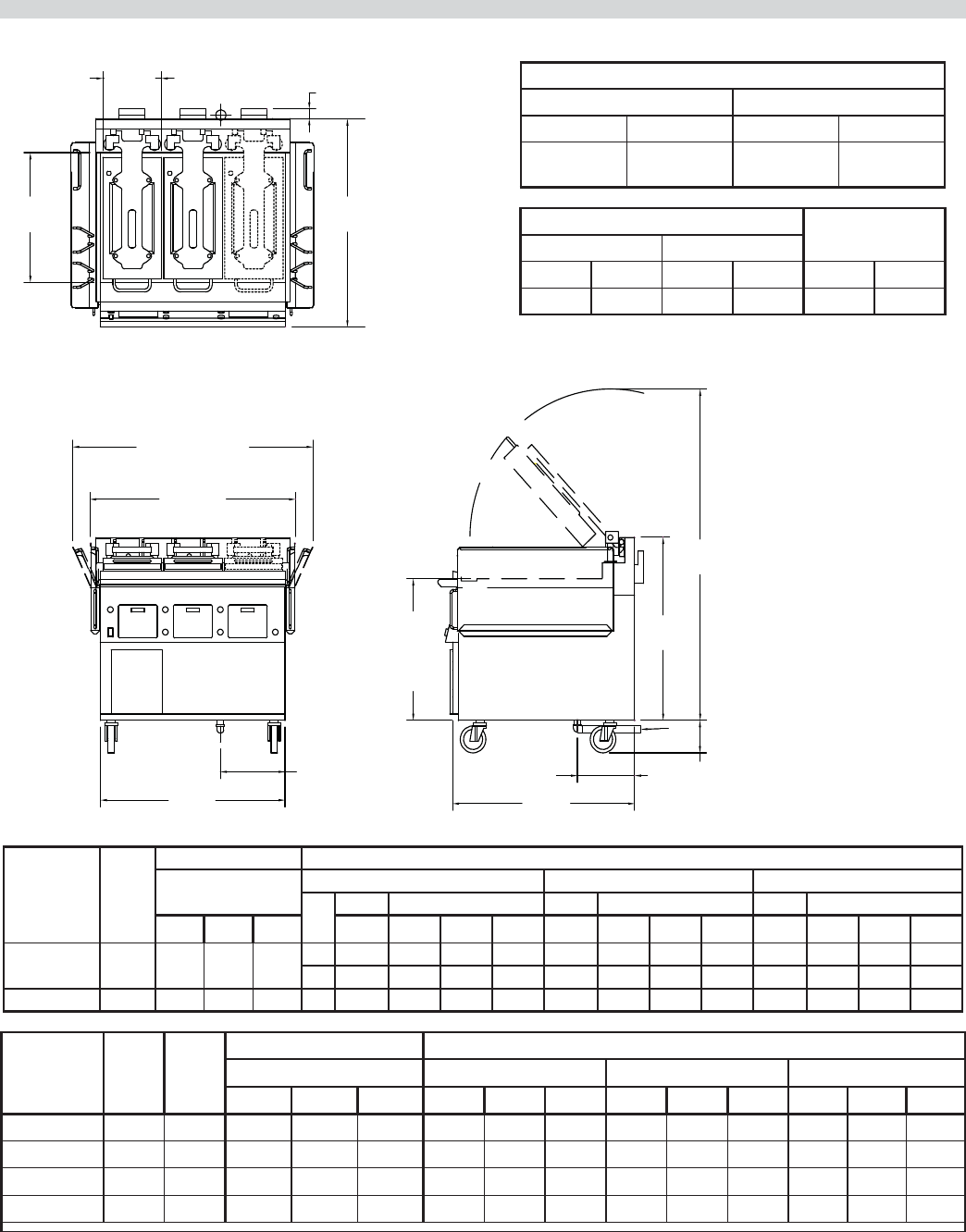
DIMENSIONS AND SPECIFICATIONS
Garland products are not
approved or authorized
for home or residential
use, but are intended for
commercial applications
only. Garland will not
provide service, warranty,
maintenance or support
of any kind other than in
commercial applications
Gas input ratings shown
here are for installations
up to 2,000 Ft. (610m)
above sea level. Specify
altitudes over 2,000 Ft.
G*
MIN: 6"
[152mm]
MAX: 9"
[229mm]
TOP
HEATER
11-1/2"
[292mm]
GRILL PLATE 24" X 36"
[610mm X 914mm]
24"
[610mm]
12-5/8"
[321mm]
GAS INLET*
47"
[1192mm]
FLARED BUCKETS
40-3/16"
[1021mm]
STRAIGHT BUCKETS
1-3/4"
[44mm]
FLUE OUTLETS*
TOP VIEW
FRONT VIEW RIGHT SIDE VIEW
61-1/4"
[1556mm]
3/4"
GAS INLET*
35-5/8"
[905mm]
36-1/8"
[918mm]
26-3/16"
[665mm]
GRILL
PLATE
HEIGHT
TOLERANCE
+/- 1/8"
[3mm]
33-7/8"
[860mm]
11-3/16"
[284mm]
GAS INLET*
38 1/2"
[978mm]
* GAS MODELS ONLY
Clearances (all models)
Entry Installation
Crated Uncrated Sides Rear
47-1/2"
(1207mm)
40-3/4"
(1035mm)
6"
(152mm)
3"
(76mm)
Gas Pressure (XG models) Total Gas Input
(XG models)
Supply (min.) Operating
NAT PRO NAT PRO BTU/Hr kW
7.0" WC 7.0” WC 3.5" WC 3.5” WC 99,000 29.1

Part # 4526884 Rev 4 (10/08/10) Page 7
INTRODUCTION
The Garland Xpress grill, for Sonic provides a method for
e cient two-sided cooking, while accommodating a variety
of products. The unit will also serve as a at grill, and meets
all of Sonic’s standards for safety, e ciency, and cleanliness.
Warranty
This warranty covers defects in material and workmanship
under normal use providing that:
a) The equipment has not been accidentally or intentionally
damaged, altered or misused.
b) The equipment is properly installed, adjusted, operated
and maintained in accordance with national and local
codes and in accordance with the installation instructions
provided with this product.
c) The warranty serial number a xed to the appliance by
Garland has not been defaced, obliterated or removed.
d) An acceptable report for any claim under this warranty is
supplied to Garland.
The equipment warranty coverage remains in force for one
(1) year (parts and labor) from the date the equipment is put
into operation.
The Garland Group agrees to repair or replace, at it’s
option, any part that proves to be defective in material or
workmanship at no charge for the part or normal labor.
We assume no responsibility for installation, adjustments,
diagnosis, or normal maintenance such as: lubrication of
springs or valves. We exclude failures caused by erratic
voltage or gas supplies. We assume no responsibility for
travel costs beyond 100 miles round trip, travel other
than overland, and overtime costs of repair. We exclude
broken glass, paint and porcelain nish, surface rust, gasket
material, ceramic material , light bulbs and fuses from normal
coverage. We exclude damage or dysfunction caused by re,
ood, and like “Acts of God” that are beyond the control of
The Garland Group.
The Garland Group’s liability on a claim of warranty shall
not exceed the price of the material and/or service , which
caused the claim. This warranty is limited and is in lieu of all
other warranties, expressed or implied. The Garland Group,
our employees, or our agents shall not be held liable for any
claims of personal injury or consequential damage or loss.
This warranty gives you speci c legal rights, and you may
have other rights which vary from state to state.
Shipping Damage Claim Procedure
Please note that the Garland equipment was carefully
inspected and packed by skilled personnel before leaving
the factory. The transportation company assumes full
responsibility for safe delivery upon acceptance of the
equipment.
What to do if the equipment arrives damaged:
1. File a claim immediately regardless of the extent of
damage.
2. Be sure to note, "visible loss or damage," on the freight
bill or express receipt and have the person making the
delivery sign it.
3. Concealed loss or damage: if damage is unnoticed until
the equipment is unpacked, notify the freight company
immediately, (within 15 days), and le a concealed
damage claim.

Part # 4526884 Rev 4 (10/08/10)Page 8
SAFETY PRECAUTIONS
Always follow these safety precautions when operating the
Xpress Grill.
• THIS GRILL MUST be operated by persons who have
been given adequate training.
• THIS EQUIPMENT MUST ONLY BE OPERATED UNDER AN
APPROVED HOOD SYSTEM.
• DO NOT operate the grill without reading this operation
manual.
• DO NOT operate the Xpress grill unless all service and
access panels are in place and fastened properly.
The Garland Xpress Grill is a semi-automatic cooking
appliance. The upper platen is lowered automatically,
following the manual, two-handed initiation of the cooking
cycle, and the upper platen is raised automatically upon
completion of the cooking cycle.
When two sided cooking, the area between the upper platen
and the griddle plate should be regarded as a “danger zone.”
During two sided cooking the operator must not be within
this danger zone. When used as a at grill, then this area is no
longer a danger zone, the platens do not move.
For whatever reason, be it cleaning, maintenance, or normal
operation, any exposed person must use extreme caution if
within this danger zone.
In two side cooking the upper platen remains in the lowered
position by nature of its own weight. It is not locked down. It
can be raised by lifting up on the handle on the front of the
platen.
The Xpress Grill may during its operation emit airborne noise
equivalent to a continuous A weighted sound pressure level
of 73dB(A).
WARNING: To avoid serious personal injury:
• DO NOT attempt to repair or replace any part of the
Xpress Grill unless all main power supplies to the grill
have been disconnected.
• USE EXTREME CAUTION in setting up, operating and
cleaning the Xpress Grill to avoid coming in contact
with hot grill surfaces or hot grease. Suitable protective
clothing should be worn to prevent the risk of burns.
• DO NOT clean this appliance with a water jet.
• DO NOT apply ICE or COLD WATER to a HOT grill surface.
• NOTE all warning labels and markings a xed to the grill.
WARNING: After turning the master power switch to the
START position, the grill will go through initialization. If
the upper platens are in the lowered position they will
return to their raised upper position. This movement takes
approximately 8 seconds.
INSTALLATION
Rating Plate Location
IMPORTANT: Rating plates for this appliance are located in
two places: 1) inside back panel on left side, 2) under front
control panel on center.
General Information
This equipment must be installed by a competent factory
trained, certi ed, licensed and / or authorized service or
installation person.
WARNING: This appliance must be properly grounded.
Prior to installation, the four casters, supplied loose with the
grill, must be securely located on the underside of the base.
The casters tted with a brake must be located at the front of
the grill.
This appliance should be connected to a potential
equalization system. A labeled equipotential bonding point
is tted to the rear of the grill.
It is recommended that this grill be connected to a residual
current,, (earth leakage),, device with a tripping current not
exceeding 30mA. The leakage current of this grill will not
exceed 5mA.
CAUTION: Prior to installation, check the electrical supply
to ensure input voltage and phase match the equipment
voltage rating and phase. See data plate located rear left side
of grill and lower front panel.
Grill is to be located directly under ventilation system.
Once installed in the grill station underneath the ventilation
system, the platens, in their highest position, must not
interfere with the lower lip of the ventilation system hood.
The raised position of each platen is adjusted by raising
or lowering the upper of the two microswitches, (limit
switches), in the rear of the grill. The lower microswitch
position must not be adjusted.
Grill plate must be level front to back, side to side and
diagonally. This leveling must be done with the unit under
the hood and in it’s normal operational position to prevent
warping of the grill plate.
NOTE: Fuses are installed to prevent damage in the event of

Part # 4526884 Rev 4 (10/08/10) Page 9
INSTALLATION
when pressure testing of that system at pressures in excess of
1/2 psi (3.45 kPa).
Check the data plate to determine the proper type of gas
before connecting the quick disconnect or piping from the
building gas supply.
An incoming gas pressure test nipple is provided on the
incoming gas manifold for pressure checks.
Minimum incoming gas pressure for Natural Gas is 6" W.C.
Maximum incoming gas pressure for Natural Gas is 13" W.C.
Minimum incoming gas pressure for Propane is 10" W.C.
Maximum incoming gas pressure for Propane is 13" W.C.
Burner operating gas pressure can be checked at the outlet
side of the gas valve at the pressure test point.
Burner manifold pressure for Natural Gas must be 3.2" W.C.;
Burner pressure for Propane must be 3.5" W.C.
To adjust the burner pressure, remove the sealing screw
from the pressure test nipple, connect a manometer, remove
the sealing cap on the gas valve regulator, turn on the grill,
adjust the screw in the regulator to give the correct pressure,
turn o the grill, re t the regulator sealing cap, remove the
manometer, replace the seal screw in the test nipple and test
for gas leaks.
Gas pressures should be checked by the local Gas Company
or an authorized service agency only.
Test all piping and connections for gas leaks. A rich soap
solution should be used for this purpose. Never use a ame.
Accessory Kit – Main Gas Inlet:
(Accessory kit part numbers 4524785 or 4525509 and also
includes electrical supply lines, see next section).
Each griddle is supplied with an extended rear gas manifold
kit., with the following parts.
DESCRIPTION PART DRAWING QTY.
3/4”x 3/4” 90 Degree Elbow
1
Nipple Assembly
1
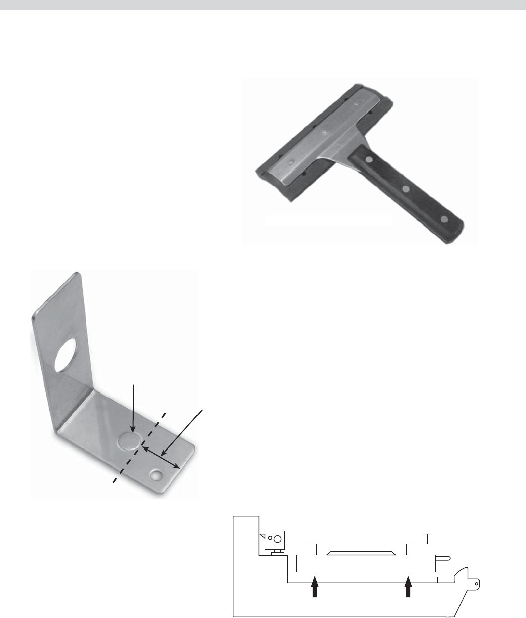
Manifold Support Bracket
1
8-32x0.375” PH PAN HD T/C
(self-tapping screws) 4
failure of the upper microswitch.
Installation shall be made with the gas connector that has
been supplied loose with the grill. The quick disconnect
tting and gas shut o valve must be installed in the
direction indicated on their outer body.
NOTE: When checking gas pressure, be sure that all other
equipment on the same gas line is on.
The appliance and its individual shut-o valve must be
disconnected from the gas supply piping system during any
pressure testing of that system pressures in excess of ½ PSIG
(3.45kPa, 14” WC).
Adequate clearance must be provided for servicing and
proper operation.
National Codes Requirements:
The type of gas for which the grill is equipped is stamped on
the data plate on the inside rear of the unit and on the lower
front panel. Connect a grill stamped for Natural Gas only to
Natural Gas.
The installation must conform to the National Fuel Gas Code
ANSI Z223.1-1998 or latest edition, NFPA No. 54 – latest
edition and National Electrical Code ANSI/NFPA 70-1990 or
latest edition and/or local code to assure safe and e cient
operation. In Canada, the installation must comply with CSA
B149.1 and local codes where applicable
In Canada, electrical connection must comply with
applicable sections of the Canadian Electrical Code, C22.1
- 1990, latest edition, “Safety Standard for Installation,
Part 1” and C22.2- No. O-M 1982 latest edition , “General
Requirements, Part 2”.
Gas Connections, and Pipe Sizing:
The size of the gas line is very important. If the line is too
small, the gas pressure at the burner manifold will be low.
This will cause slow recovery and delayed ignition. The
incoming gas pressure line should be a minimum of 1-1/2".
All grills require a 3/4" connection.
Before connecting new pipe the pipe must be blown out to
dispose of any foreign particles. These particles will cause
improper operation.
When using thread compound, use small amounts on male
threads only. Use a compound that is not a ected by the
chemical action of LP gases. Avoid applying compound
to the rst two threads to prevent clogging of the burner
ori ces and control valve.
Have the installer check all gas plumbing with a soap
solution for leaks. DO NOT USE matches, candles or other
ignition sources in checking for leaks.
The grill must be disconnected from the gas supply system
Part # 4526884 Rev 4 (10/08/10)Page 10
INSTALLATION continued
Installation of Kit:
1. Install the nipple assembly in the reduction elbow
(3/4” NPT) connected to the manifold. (Figure A)
Figure A
2. Install the manifold support bracket over the nipple and
leave the two screws loose. (Figure B)
Figure B
3. Adjust the manifold support bracket ush with the rear
gas support bracket. (Figure C)
Figure C
4. Tighten the two loose screws of the manifold support
bracket onto the frame U-channel.
5. Lock the two brackets together using two screws.
(Figure C)
6. ¾” 90 degree elbow is supplied, to be installed if required.
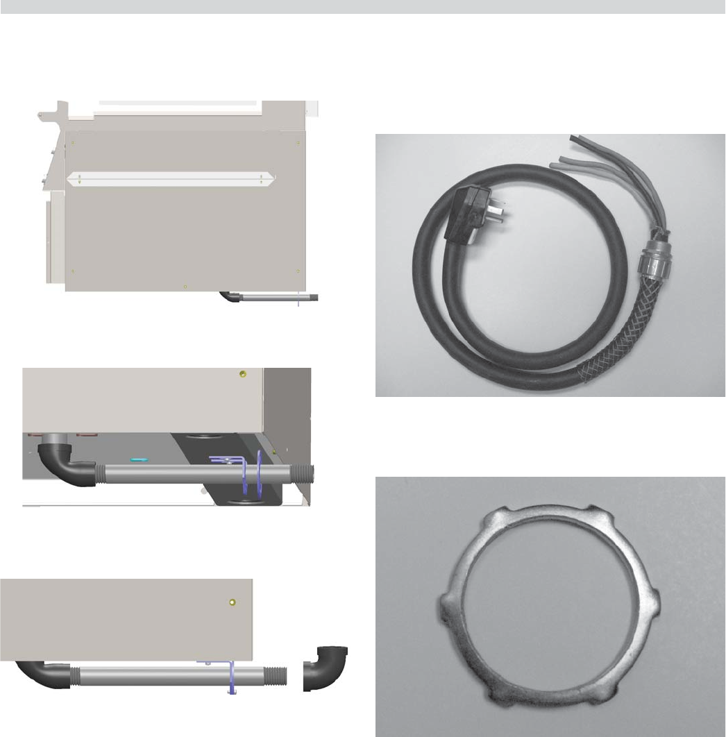
Accessory Kit – Electrical Supply Lines:
The accessory kit also contains electric power cord and
plug and has a stain relief suited for each unit. See Plug
Con guration in SPECIFICATIONS and Photo D
Installation of Cord And Plug With Strain Relief:
1. Remove the left grease bucket support attached by two
metal screws and the stainless steel left side body panel
attached by ve metal screws.
2. Remove the cord & plug and strain relief assembly from
the accessory kit. Refer to photo D.
Photo D
3. Remove the locknut from at the end of the cord. Refer to
photo E.
Photo E
4. Insert loose wires and strain relief cord end through the
hole at the bottom of the unit Refer to photo F and secure
with locknut. Refer to photo E.
Part # 4526884 Rev 4 (10/08/10) Page 11
INSTALLATION continued
Photo F
5. Attached wire ends to terminal block as shown in next
section and referenced in wiring diagrams at back of this
manual.
6. Reinstall the side panel and grease bucket support with
metal screws. The external electrical connection should
appear as in photo G.
Photo G
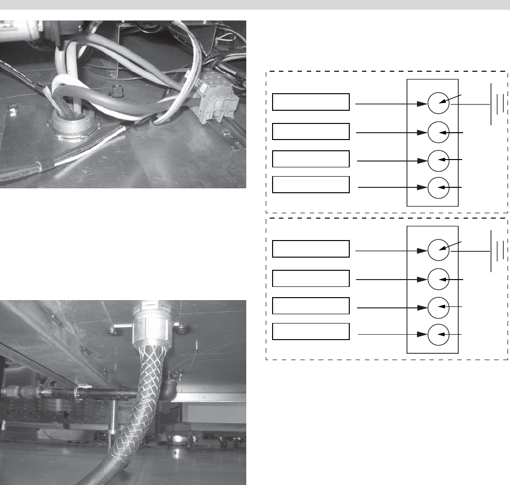
Electrical Connection
Terminal Block Connection
All electrically operated appliances must be electrically
grounded in accordance with local codes; or in the absence
of local codes, with the latest edition of National Wiring
Regulations. A wiring diagram is located behind the rear
panel of the grill. For proper voltages, see rating plate in the
circuit breaker box, or on the right-rear frame upright.
Note: see diagram below for connections to terminal block.
Green-Ground
White - Z
Black - Y
Red - X
Wire leads from
Cord and Plug
3-PHASE
Main Terminal
Block of Grill
G
Z
Y
X
Green-Ground
Black - Z
White - Y
Red - X
SINGLE PHASE
G
L1
N
L2
Grease Bucket:
The griddle is supplied with two stainless steel side grease
buckets that must be installed before the unit is used. Each
bucket slides into position along stainless steel supports.
Appliances Equipped with Casters:
1. The installation shall be made with a connector that
complies with the Standard for Connectors for Moveable
Gas Appliances, ANSI Z21.69 or latest edition, addenda
Z21.69a-1989, and a quick-disconnect device that
complies with the Standard for Quick Disconnects for Use
with Gas Fuel. ANSI Z21.41 or latest edition.
2. The front casters on the appliance are equipped with
brakes to limit the movement of the appliance without
placing any strain on the connector or quick-disconnect
device or its associated piping.
3. Please be aware; required restraint is attached to a
bracket (which is located on the rear caster closest to the
gas connection), and if disconnection of the restraint
is necessary; be sure to reconnect the device after the
appliance has been returned to its original position

Part # 4526884 Rev 4 (10/08/10)Page 12
INSTALLATION continued
Appliances Equipped with Casters:
1. The installation shall be made with a connector that
complies with the Standard for Connectors for Moveable
Gas Appliances, ANSI Z21.69 or latest edition, addenda
Z21.69a-1989, and a quick-disconnect device that
complies with the Standard for Quick Disconnects for Use
with Gas Fuel. ANSI Z21.41 or latest edition.
2. The front casters on the appliance are equipped with
brakes to limit the movement of the appliance without
placing any strain on the connector or quick-disconnect
device or its associated piping.
3. Please be aware; required restraint is attached to a
bracket (which is located on the rear caster closest to the
gas connection), and if disconnection of the restraint
is necessary; be sure to reconnect the device after the
appliance has been returned to its original position.
Swivel Caster Installation
Prior to installation, the four casters, supplied loose with the
grill, must be securely located on the underside of the base.
The casters tted with a brake must be located at the front of
the grill.
1. Carefully remove the top and side packaging leaving the
grill on shipping pallet.
DO NOT REMOVE THE TIES SECURING THE PLATEN ARMS
TO THE GRILL TOWEL BAR.
2. Raise the grill vertically o the pallet to a comfortable
working height and install the casters. DO NOT TIP THE
GRILL ON ITS BACK OR SIDE. If a truck lift is used, be
careful when inserting the lifting arms under the grill as
the gas inlet elbow is protruding in the center of the base.
WARNING - GRILL WEIGHT IS APPROXIMATELY 800 LBS –
USE CAUTION
3. Install the casters as shown below. The two casters with
brakes go on the front, and the two without on the rear.
WITH
BRAKE WITHOUT
BRAKE
NOTE: CASTERS MUST BE THREADED INTO GRILL BASE
LEAVING APPROXIMATELY ONE INCH OF EXPOSED
THREAD. THIS IS THE STARTING POINT FOR LEVELLING THE
GRILL AFTER IT IS IN POSITION.
Ventilation and Clearance:
One of the most important considerations for e cient grill
operation is proper ventilation and air supply. Insure the
grill is installed so the products of combustion are removed
e ciently and the ventilation system does not produce
drafts that interfere with proper burner operation.
Proper operation of exhaust fans (speed, rotation and
adjustment) is essential. In addition to the exhaust system
the make-up air system, (HVAC), for the kitchen is the
air supply for the combustion air for the burners. Proper
incoming air is essential for all gas operated equipment. Poor
incoming make-up will cause ine cient burner operation,
delayed ignition and possible burner failure.
Any ventilation system will break down if improperly
maintained. The duct system, the hood, and the lters must
be cleaned on a regular basis and kept grease free.
The room containing the grill is required to have a
permanent air vent. The minimum e ective area of the vent
shall be 0.7 in.² per kW. Air vents shall be of such a size to
compensate for the e ects of any extract fan in the premises.
Changing to a di erent type of gas
Changing from one gas type to another must only be
done by a Quali ed Gas Engineer and according to local
regulations.
Part # 4526884 Rev 4 (10/08/10) Page 13
Master Power Switch:
Controls power to the grill and must be turned “ON” to start
operation. The controller display will be active when the
switch is “ON”.
LED Indicators:
There are two, (2), indicator lights, indicating the
temperature status of each control’s heat zones; one, (1), on
the upper platen, (top light), and one, (1), on the grill surface.
Each light can display three, (3), di erent colors, indicating
temperature status for the corresponding zone.
Red: The zone is too hot, (more than 79°F/45°C over the set
temperature), or heat zone failure.
Amber: The zone is calling for heat.
Green: The zone is at or above the set temperature.
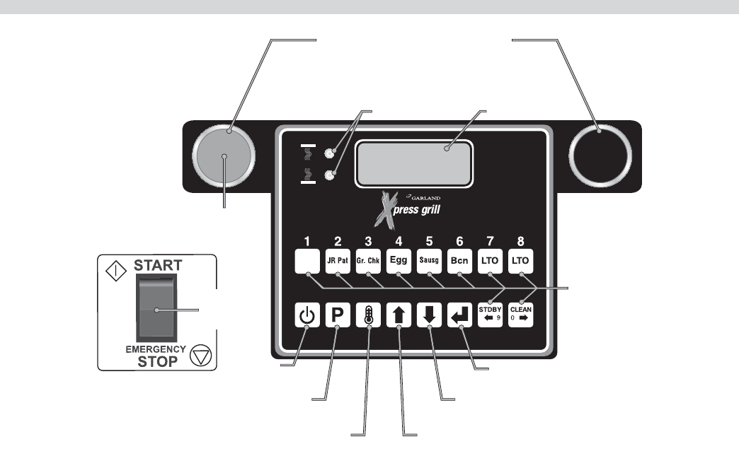
Display:
The controller display will contain information relevant to
each operation in both cook and program modes.
16-CHARACTER
2-LINE DISPLAY
PRODUCT
BUTTONS
LED
INDICATORS
POWER
BUTTON
PROGRAM
BUTTON
TEMPERATURE
BUTTON
ENTER
BUTTON
DOWN ARROW
BUTTON
UP ARROW
BUTTON
WHEN PUSHED SIMULTANEOUSLY:
"START COOK TIME COUNTDOWN" (flat grill cooking)
OR "LOWER PLATEN" (two-sided cooking)
MASTER
POWER
SWITCH
CANCEL/
RAISE PLATEN
BUTTON
BIG PAT
GRILL CONTROLS
Product Buttons (0-9):
Buttons 0-9 can be assigned to product items. Buttons 9 and
0 are used to move the cursor left or right when creating
or modifying product names in “PROD NAME LIB” program
mode.
Power Button:
After the main power switch is turned on, this button will put
the control into cook mode. If pressed again, the control will
go back to displaying “OFF.”
Program Button:
The primary function is to access Programming and
Calibration of the grill. Push and hold for ve (5) seconds.
Display will ask for the code. After entering code, ve
programming features will be accessible “MENU ITEMS,”
“SYSTEM INFO,” “SYSTEM SETUP,” “SERVICE MODE,” and
“PRODUCT NAME LIB.”

Part # 4526884 Rev 4 (10/08/10)Page 14
GRILL CONTROLS continued
Temperature Button:
In the Cook mode, each time the button is pressed the
current temperature for one zone is displayed. The grill
temperature is displayed rst followed by the platen
temperature. After ve (5) seconds, the display will return to
the menu item selected.
Up/Down Arrow Buttons; 2 Functions:
1. In the cook mode, the Up/Down Arrow Buttons will cycle
through the di erent menu items.
2. In the program mode, the Up/Down Arrow Buttons will
change the value of the current setting.
Enter Button:
Function is to accept programming steps.
Cancel/Raise Platen Button, (Green):
During the cooking cycle, pressing this button will cancel the
cooking timer and return the grill to the “IDLE” mode. This
button will also bring the grill out of STANDBY.
Black Button:
When both Black and Green “CANCEL/RAISE” buttons are
pressed simultaneously, the upper platen will lower to the
griddle surface.
Main Pre-Programed Product Items
Abbrev Cook Time Upper Platen Upper Temp Grill Temp Gap Key
Assingment
BIG PAT 2:00 YES 425°F 350°F 0.420 1
JR Pat 1:10 YES 425°F 350°F 0.300 2
Gr. Chk. 1:45 YES 425°F 350°F 0.460 3
Sausg 1:30 YES 425°F 350°F 0.320 4
Egg :50 YES 425°F 350°F 0.310 5
Bcn 1:15 YES 425°F 350°F 0.100 6
LTO 1:20 YES 425°F 350°F 0.320 7
LTO 1:20 YES 425°F 350°F 0.320 8
STDBY N/A YES 425°F 350°F 0.400 9
CLEAN N/A YES 220°F 220°F 0.250 10
Part # 4526884 Rev 4 (10/08/10) Page 15
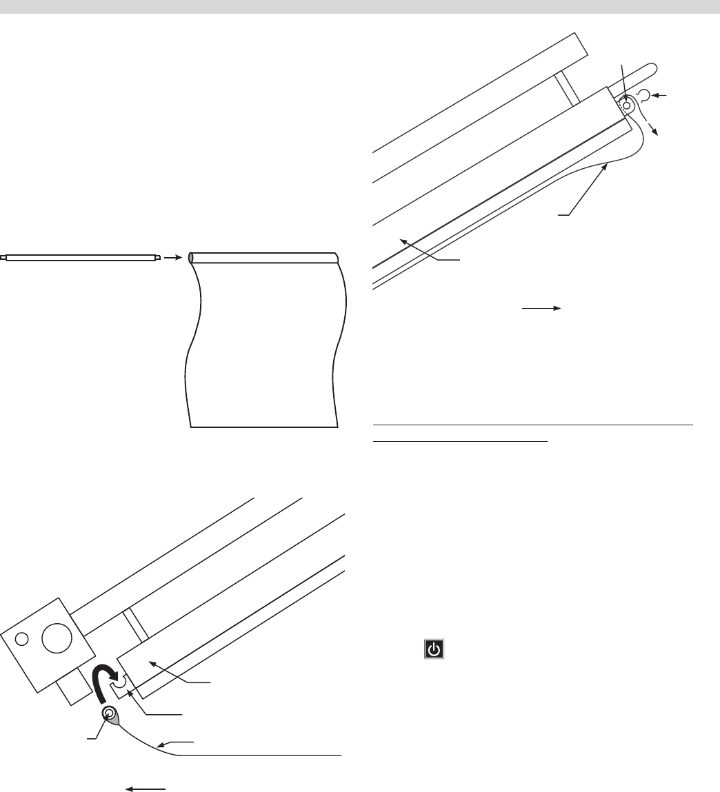
Installing Release Material:
A release material sheet must be replaced when:
• Product sticks to release material.
• Carbon build-up ruins taste or appearance.
• Tearing occurs in the sheet’s cooking area.
• Release material coating is worn o sheet.
Slide release material rod through hemmed end of the
release material sheet.
Hook release material rod on brackets located at the rear of
the upper plate
Holding the bottom of the release material sheet in place,
gently pull the sheet toward the front of the platen.
UPPER PLATEN (side view
)
RELEASE MATERIAL HOOK
RELEASE
MATERIAL ROD RELEASE MATERIAL SHEET
REAR OF GRILL
Thread the front edge of the release material sheet behind
the release material bar on the front of the platen, then
around the top and down over the front of the bar as shown.
Place locking clips over release material sheet and press into
place over release material bar.
Check alignment and tightness of release material against
upper platen.
OPERATION
UPPER PLATEN (side view)
RELEASE
MATERIAL
BAR RELEAS
E
MATERIA
L
LOCKING
CLIP (1)
RELEASE
MATERIAL
FRONT OF GRILL
NOTE: Make sure release material ts smoothly over upper
platen. Installing release material sheets too tight may cause
premature failure of the sheet.
Release sheets are reversible and should be ipped over
and reattached on a daily basis. For instructions on cleaning
release sheets, see Step 17., under Daily Cleaning in Cleaning
and Maintenance section
Lighting Instructions:
1. Ensure that the exible gas hose is connected to the grill
and the power cord is plugged into the receptacles.
2. Turn the main power switch ON and allow the controls
to go through the power-up self-check. Once the control
panel displays the word “OFF” the unit is ready to begin
the heating process.
3. Press . The control will automatically initiate the
heating cycle. The burner will ignite and heat until the
temperature speci ed by the menu item has been
obtained.
If ignition of the burner does not occur on the rst trial, the
bottom indicator light will ash amber. If the burner(s) do
not light within four trials for ignition, the control will display
a ashing warning, “IGNITION ERROR.” The ashing amber
light will turn to solid red and an audible alarm will sound. If
this occurs, turn the main power switch o , wait 5 minutes,
and then repeat steps 2 and 3.
Part # 4526884 Rev 4 (10/08/10)Page 16
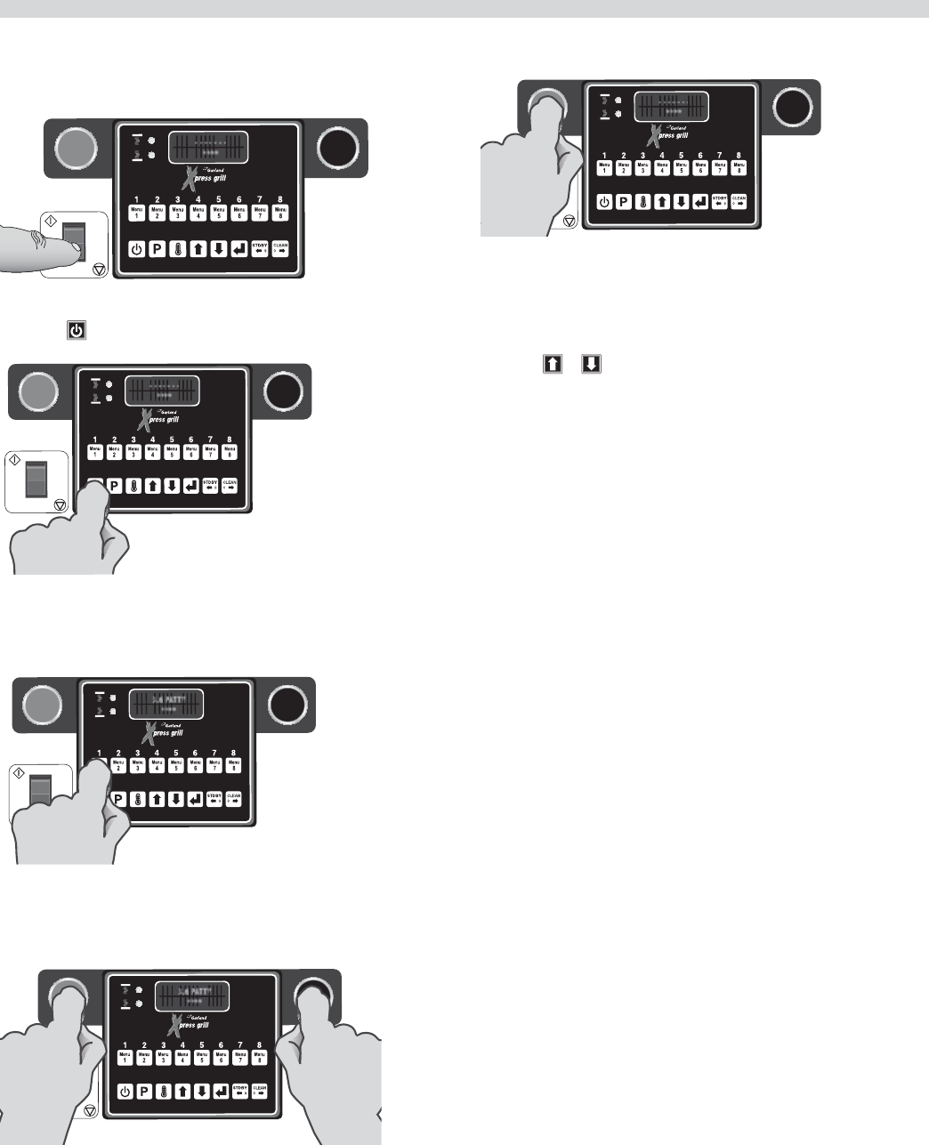
Simpli ed Cook Cycle Instructions:
1. Press button to turn on mainpower to grill.
- - - - - - -
****
START
STOP
EMERGENCY
2. Press to turn zone power on.
- - - - - - -
****
START
STOP
EMERGENCY
3. Load product on grill surface and select the
corresponding product key.
3.6 PATTY
****
START
STOP
EMERGENCY
4. Press both green and black buttons to lower clam and
begin cooking product.
3.6 PATTY
****
START
STOP
EMERGENCY
OPERATION continued
5. Press green button to cancel any time during cook cycle.
- - - - - - -
****
START
STOP
EMERGENCY
To Cook in Two-Sided Mode:
1. To start a cook cycle select a product recipe by using the
product keys (1 through 9) or by using the UP/DOWN
keys or to select a product recipe.
The display alternately blinks the recipe and the word
SELECTED 2 times then the recipe displays continuously.
2. The controller regulates the platen and grill temperatures
to the set temperatures of the product selected and
reads “TOO COOL” or “TOO HOT” with “MENU ITEM”, until
the grill attains the set temperature range for the item.
NOTE: If the display reads either “TOO COOL” or “TOO HOT”
the upper platen will not lower and initiate a cooking
sequence.
3 After loading the product onto the grill, press the green
CANCEL/RAISE PLATEN BUTTON and BLACK button
simultaneously. A cook cycle starts and the upper platen
lowers if the product selected is clamshell recipe.
4 To cancel a cook cycle at anytime press the green
CANCEL/RAISE PLATEN BUTTON and the upper platen
will rise if the product recipe selected is clamshell recipe.
5. During a cook cycle, the display shows the product recipe
name in the rst line and the remaining cook time count
down in the second line.
6 When the cook timer reaches one, (1), second remaining
a pre-time-out alarm sounds alerting the operator.
7 When the cooking time has been completed the platen
raises automatically. On the controller the “PRODUCT
NAME” and the word “REMOVE” will be displayed and an
audible alert will sound.
8. Pressing the green CANCEL/RAISE PLATEN BUTTON stops
the audible alert and the unit will revert back to IDLE
mode.

Part # 4526884 Rev 4 (10/08/10) Page 17
To Cook in Flat Grill Mode:
1. To start a cook cycle select a product recipe by using the
product keys (1 through 9) or by using the UP/DOWN
keys or to select a product recipe.
The display alternately blinks the recipe and the word
SELECTED 2 times then the recipe will be displayed
continuously.
2. The controller regulates the grill temperature to the set
temperature of the product selected and reads “TOO
COOL” or “TOO HOT” with “MENU ITEM”, until the grill
attains the set temperature range for the item.
NOTE: If the display reads either “TOO COOL” or “TOO HOT” it
will not initiate a cooking sequence.
3 After loading the product onto the grill, press the green
CANCEL/RAISE PLATEN BUTTON and BLACK button
simultaneously. That will start a cook cycle if the product
selected is clamshell recipe.
4 To cancel a cook cycle at anytime the press the green
CANCEL/RAISE PLATEN BUTTON .
5. During a cook cycle, the display shows the product recipe
name in the rst line and the remaining cook time count
down in the second line.
6. The display shows the “SEAR” or “FLIP” alarm message
with ashing in the second line if the current cooking
product is at recipe and the sear time or ip time is not
zero.
7. A cook alarm sounds with a repeating beep pattern.
Pressing the black RAISE button acknowledges the “SEAR”
or “FLIP” alarm message if the alarm eld in system setup
is set to MANUAL.
8. The “SEAR” or “FLIP” alarm message stops after 5 seconds
if the alarm eld in system setup is set to AUTO.
9. When a cook is complete, the display shows the product
recipe name in the rst line and a ashing “REMOVE”
message in the second line. A repeating beeping alarm
also sounds.
10. Pressing the black RAISE button cancels the cook done
alarm.
11. The unit revertes back to IDLE mode.
OPERATION continued
Enter Standby Mode:
Stand by mode is used during slow periods to conserve
energy with out a complete shut down of the unit. When
cooking temperatures are again required, pre-heat cook
temperature/time is reduced. Stand by mode temperatures
can be adjusted, see the PROGRAMING section.
1. Select Standby Mode by pressing or until
“STANDBY” is displayed.
2. Press the GREEN (‘CANCEL/RAISE’) and the BLACK buttons
at the same time. As soon as the upper platen moves
down, the display will read “STANDBY MODE.” (Note: The
rst time Standby Mode is entered, the display prompts
the operator to press ENTER after pressing the GREEN
and BLACK buttons.)
Exit Standby Mode:
1. Press the GREEN (‘CANCEL/RAISE’) button. The upper
platen will raise and the display will read “CANCEL” with
an audible alarm.
To Display the Current Temperatures:
1. Press the button and repeat for each zone to be
displayed...
1st press - LOWER GRILL ZONE
2nd press - UPPER PLATEN
NOTE: The temperatures may be displayed at any time,
including during a cooking cycle.
To View Settings for a Menu Item:
1. Enter Programming; Menu Items, (see Programming)
2. Press to enter “PROGRAMMING MODE MENU ITEMS”
3. Use and to choose the desired Menu Item.
4. Press to scroll through settings for the chosen item.
To Clean the Grill:
1. To start a CLEAN MODE select the clean mode recipe by
pressing product key 10 or by using the UP/DOWN keys
or to select the clean mode recipe.
2. The controller regulates the platen and grill temperatures
to the set temperatures of the clean mode recipe. The
display shows the message “CLEAN MODE” in the rst line
and the actual grill temperature in the second line.
Part # 4526884 Rev 4 (10/08/10)Page 18
CLEANING AND MAINTENANCE
Cleaning During Operation:
1. After each product load is removed, Use a grill scraper to
scrape grease on lower grill plate from front to back only.
Do not scrape left to right across the lower grill plate with
the grill scraper.
2. Use a grill squeegee to clean release material sheet on
upper platen in a downward motion. Do not press hard
against the release material sheet to prevent scratching
or tearing.
3. Push the grease to the rear of the grill, or pull it to the
3. Press the ENTER key to initiate the clean mode.
4. The display SHOWS the message “READY TO CLEAN” with
ashing in the second line when the actual temperature
is reached (or greater than the set temperatures of clean
mode recipe (default 250 F for both the platen and grill)).
A 5 second repeating beep pattern is sounded.
5. Press the ENTER key again, the heater’s control for the
platen and grill are turned o and the display shows the
message “CLEANING” with ashing in the second line.
6. Press the ENTER key again to exit the CLEAN MODE. The
display shows the message “STANDBY” in the rst line.
The control transitions to “STANDBY MODE” and preheats
to idle condition.
PLATEN SET:
This function allows the platen to be moved up or down
once it is parallel to the grill surface. Values range from –160
to +160.
OPERATION continued EXTENDED TIME:
This option will add 6, 4 and 2 seconds to the time of the next
three cooks respectively if the grill has had no activity for
5 minutes. Provided the temperature is not 25°F above set
temperature for either the grill or the platen.
INSTANT ON TIME:
This can be set in the range of 00:00 to 00:40. Instant on will
turn on the heat zone(s) as soon as a cook cycle starts.
START DELAY:
This number is how long the operator must hold the GREEN
(‘CANCEL/RAISE’) and BLACK buttons to start a cooking cycle
for 2-sided recipes only. There will be one beep when the
cook is started and another beep when the START DELAY
time is reached. If the GREEN (‘CANCEL/RAISE’) and BLACK
buttons are released before that time the cook will be
canceled. If Yes is toggled press enter to allow the user to
pick from 1 to 5 seconds in 0.5 second increments using
and .
Daily Cleaning:
Warning: The upper platen surface and edges are very hot! To prevent burn injuries, use extreme caution when wiping
down release sheets and platen edges.
front trough. Then, squeegee the grease into the buckets
on either side. Do not use the scraper for this step.
4. Use a clean, damp cloth to clean back splash and
bullnose areas as needed during operation.
Note: To increase life of release material sheets, wipe them
down with a folded clean, damp cloth at least four times
during each hour of operation.
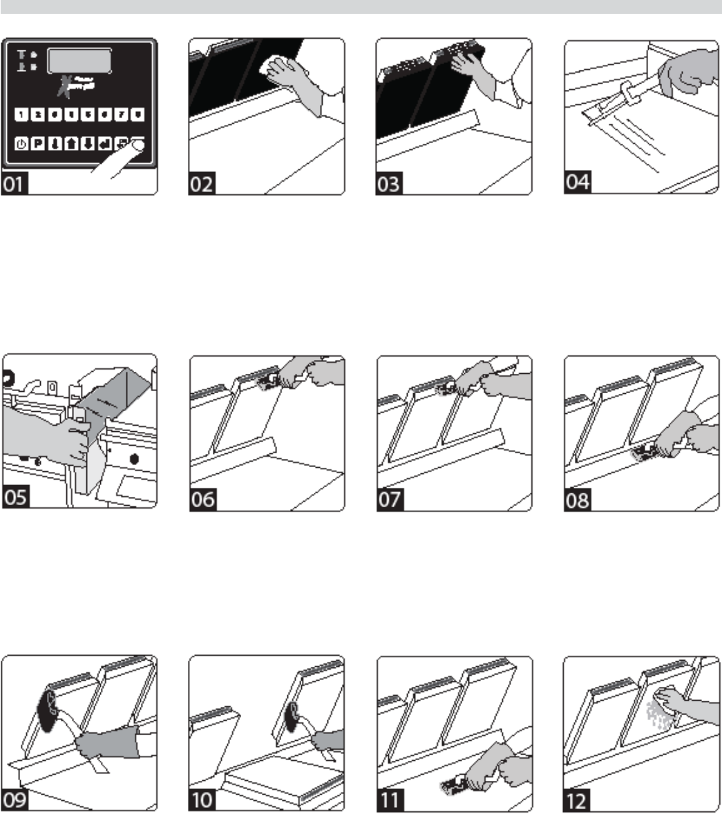
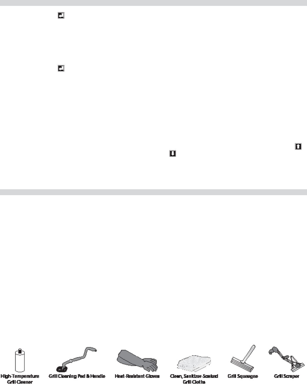
Part # 4526884 Rev 4 (10/08/10) Page 19
• Remove the grease trough
from each side. Empty and
replace.
• Apply the grill cleaner
to front side of platens
starting from right platen
to left platen.
• DO NOT SCRUB
• Apply the grill cleaner to
platen surfaces starting
from right platen to left
platen.
• DO NOT SCRUB
• Apply the grill cleaner to
back side of platens from
right platen to left platen.
• DO NOT SCRUB
• Select Clean Mode.
When Clean Mode has
been reached, the LED
indicators will turn GREEN
• Wipe the Release Material
sheets with a clean,
sanitizer-soaked grill cloth.
• Remove the locking clips,
bars, and release sheets.
Wash, rinse, and set aside
to dry.
• Set release sheets aside on
a at surface.
• Scrape the lower grill
surface with the scraper.
• Use the grill squeegee to
push residual grease into
trough.
• Wash and rinse the
squeegee and scraper
• Apply the grill cleaner to
outer edges of right and
left platens.
• DO NOT SCRUB
• Press green & black
buttons to lower the
center platen.
• Apply grill cleaner to inner
edges of the right and left
platens, and the edges of
the center platen.
• DO NOT SCRUB
• Press green button to raise
center platen.
• Apply grill cleaner to
bottom grill surface.
• Spread the cleaner over
the entire lower grill
surface from front to back
using even strokes.
• DO NOT SCRUB
• Rinse platen surfaces with
a clean, sanitizer-soaked
grill cloth, starting from
right to left platens.
• Press green & black
buttons to lower the
center platen.
CLEANING AND MAINTENANCE continued
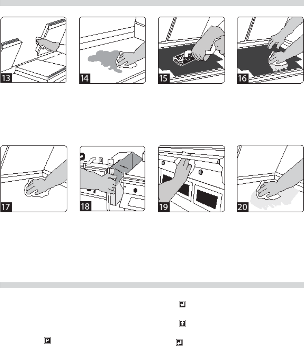
Part # 4526884 Rev 4 (10/08/10)Page 20
• Rinse the edges of all
three platens.
• Press green button to raise
center platen.
• Pour a small amount of
lukewarm water on a
clean, sanitizer-soaked
grill cloth over the bottom
grill surface and wipe o
residue.
• Place upper platen release
material sheets at on the
lower grill surface.
• Gently clean both sides of
the release material sheets
with the grill cleaning pad.
• Rinse both sides of the
release material sheets
with a clean, sanitizer-
soaked grill cloth.
• Reinstall the release
material sheets. Secure in
place with bars and clips.
• Wipe lower grill with a
clean,sanitizer-soaked
grill cloth. Repeat until no
visible soil remains.
• Empty, wash, rinse,
and replace the grease
troughs.
• Wipe remaining grill
surfaces with a clean,
sanitizer-soaked grill cloth.
• Apply a thin coat of fresh
shortening to the lower
grill surface only.
CLEANING AND MAINTENANCE continued
PLATEN ZEROING
Turn Master power switch “ON”, wait for controllers to display
“OFF”.
Note: Release sheets should not be installed during this
procedure.
1. Press and hold for three, (3) seconds. “ENTER CODE” is
displayed.
2. Using the Product buttons, 0-9 enter the code, (1251).
“ENTER CODE **** ” is displayed.
3. Press to enter the Programming Mode.
“PROGRAMMING MODE MENU ITEMS” is displayed.
4. Press two, (2) times in succession to display
“PROGRAMMING MODE SYSTEM SETUP.”
5. Press six, (6) times. “PLATEN SET +/- XX” is displayed.
(XX=numbers that will vary from grill to grill.)
6. Allow time for grill to heat and turn ready. Press
both the Cancel (Green) and Standby (Black) buttons
simultaneously to lower the upper platen. Press the
Part # 4526884 Rev 4 (10/08/10) Page 21
PLATEN ZEROING
Cancel (Green) button to raise the platen. Now, press
both the Cancel (Green) and (Black) Buttons to re-lower
the platen.
7. Remove platen adjuster caps from all four adjustment
points on each platen. Remove the four locking caps from
the adjustment points.
8. Using the adjusting tool lower platen until adjusting tool
touches the arm assembly.
9. With gapping tool, adjust right rear of platen until the
gapping tool ts snugly between the upper platen and
grill surface.
10. Move next to the left front adjuster and raise the platen
until the gapping tool ts snugly between the upper
platen and grill surface.
11. Next go to the left rear adjuster and raise the platen until
the gapping tool ts snugly between the upper platen
and grill surface.
12. Move next to the right front adjustment and raise the
platen until the gapping tool ts snugly between the
upper platen and grill surface.
13. Repeat steps 9-12 one or more times until gapping tool
ts snugly between the upper platen and grill surface at
all four adjustment points without further adjustment.
(See diagram below.)
14. Replace the platen adjuster locking caps “hollow side
down” and tighten snugly. Replace platen adjuster caps.
15. Repeat steps 9-14 for each platen.
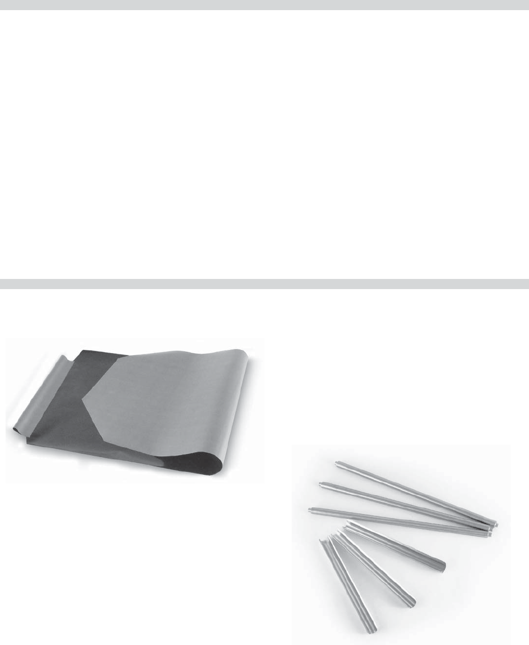
Teflon Release Material Sheet - 1799303
(one per platen)
ACCESSORIES
Teflon Release Material Rod - 4517008
(one per platen; 3 shown)
Teflon Release Material Clip - 1851301
(one per platen; 3 shown)
Part # 4526884 Rev 4 (10/08/10)Page 22
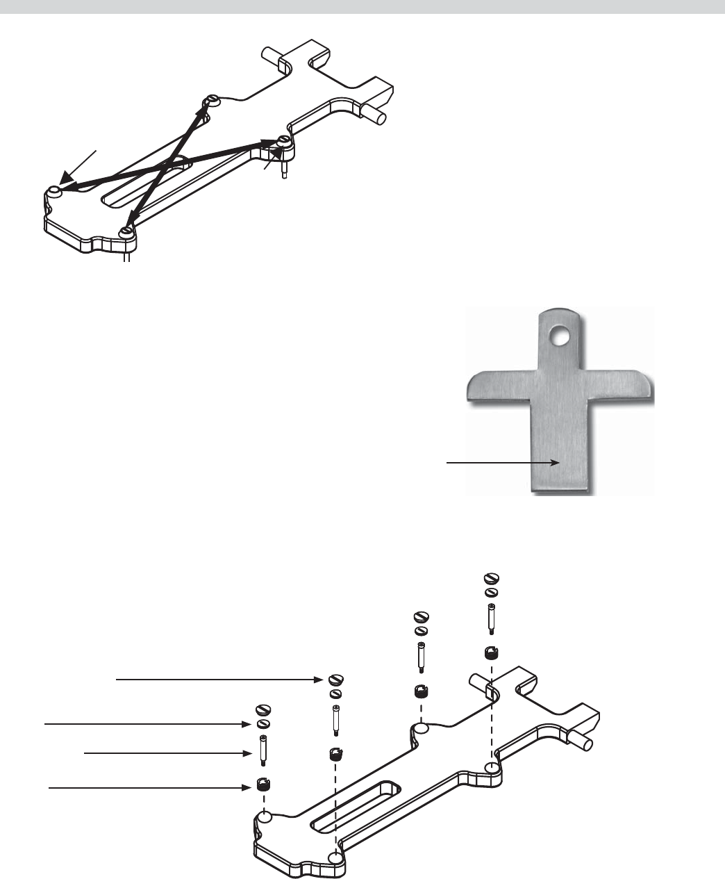
Insert gap tool directly below platen adjusters.
“No-Go”
“Go”
Platen Gapping Tool -1838701
ACCESSORIES
Grill Squeegee - 1868201
Part # 4526884 Rev 4 (10/08/10) Page 23
PLATEN ZEROING continued
Raise
Back
Right
Lower
Front
Left
Platen leveling should be done from one corner
to the opposite corner. The adjuster nuts should
be turned opposite of one another.
Platen Adj Lock Nut - 1859103
Shoulder Bolt - 8005401
Platen Adjuster Nut - 1859101
Platen Adjuster Cap - 1859102
Use this end to turn all slotted
adjuster caps and nuts
Platen Adjusting Tool - 4523323
Part # 4526884 Rev 4 (10/08/10)Page 24
System Information
26
26
26
26
26
27
27
27
27
27
28
28
28
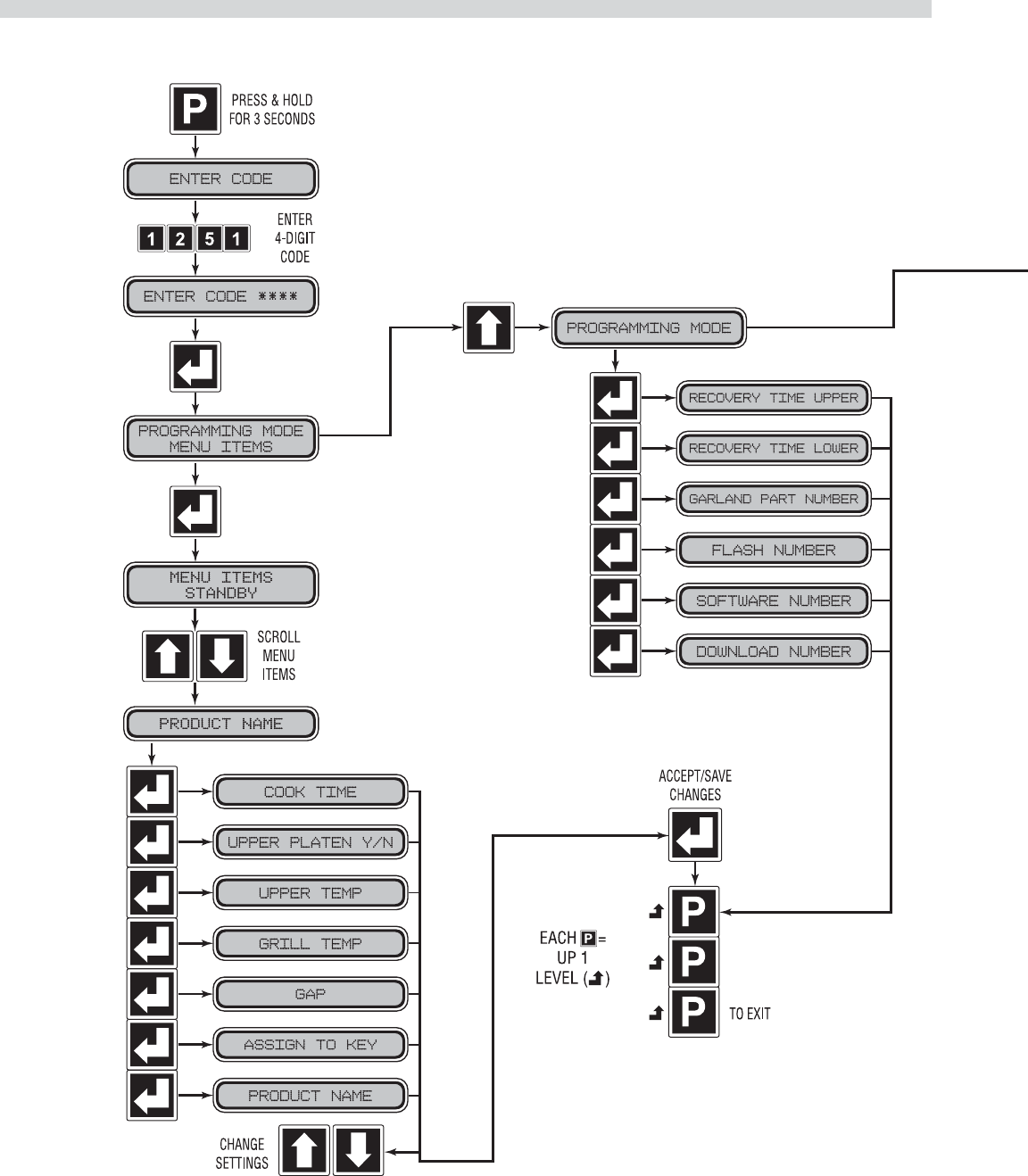
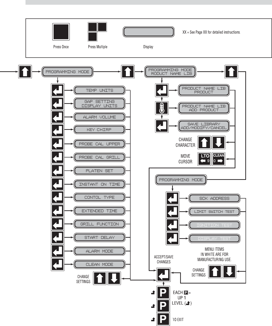
PROGRAMMING
Programming Modes/Menu Sequence:
Part # 4526884 Rev 4 (10/08/10) Page 25
Service Mode
System Set-up
28
28
29
29
29
29
30
30
30
30
31
31
31
31
31
32
32
30
30
PROGRAMMING continued

Page 26
PROGRAMMING continued
Menu Items...
To Change the Cook Time of a Product:
1. Press and hold for three, (3) seconds. “ENTER CODE” is
displayed.
2. Using the Product buttons, 0-9 enter the code, (1251).
“ENTER CODE **** ” is displayed.
3. Press to enter Programming Mode. “PROGRAMMING
MODE MENU ITEMS” is displayed.
4. Press . “MENU ITEMS STANDBY” is displayed.
5. Use and to choose the desired Menu Item.
6. Press to display “(MENU ITEM) COOK TIME XX:XX”
7. Use and to adjust the cook time.
8. Press to save the changes.
9. Press twice to exit.
To Turn Platen, (2-Sided), Cooking On/O :
1. Press and hold for three, (3) seconds. “ENTER CODE” is
displayed.
2. Using the Product buttons, 0-9 enter the code, (1251).
“ENTER CODE **** ” is displayed.
3. Press to enter the Programming Mode.
“PROGRAMMING MODE MENU ITEMS” is displayed.
4. Press . “MENU ITEMS STANDBY” is displayed.
5. Use and to choose the desired Menu Item.
6. Press twice to display “(MENU ITEM) UPPER PLATEN
YES/NO “.
7. Use and to turn upper platen on or o .
8. Press to save the changes.
9. Press twice to exit.
To Change Upper Platen Set Temperature:
1. Press and hold for three, (3) seconds. “ENTER CODE” is
displayed.
2. Using the Product buttons, 0-9 enter the code, (1251).
“ENTER CODE **** ” is displayed.
3. Press to enter the Programming Mode.
“PROGRAMMING MODE MENU ITEMS” is displayed.
4. Press . “MENU ITEMS STANDBY” is displayed.
5. Use and to choose the desired Menu Item.
6 Press three, (3) times to display “(MENU ITEM) UPPER
TEMP XXX” displayed in °F or °C.
7. Use and to change the set temperature to the
desired value.
8. Press to save the changes.
9. Press twice to exit.
To Change Grill Set Temperature:
1. Press and hold for three, (3) seconds. “ENTER CODE” is
displayed.
2. Using the Product buttons, 0-9 enter the code, (1251).
“ENTER CODE **** ” is displayed.
3. Press to enter the Programming Mode.
“PROGRAMMING MODE MENU ITEMS” is displayed.
4. Press . “MENU ITEMS STANDBY” is displayed.
5. Use and to choose the desired Menu Item.
6. Press four, (4) times to display “(MENU ITEM) GRILL
TEMP XXX” displayed in °F or °C.
7. Use and to change the set temperature to the
desired value.
8. Press to save the changes.
9. Press twice to exit.
To Change Product Gap Setting:
1. Press and hold for three, (3) seconds. “ENTER CODE” is
displayed.
2. Using the Product buttons, 0-9 enter the code, (1251).
“ENTER CODE **** ” is displayed.
3. Press to enter the Programming Mode.
“PROGRAMMING MODE MENU ITEMS” is displayed.
4. Press . “MENU ITEMS STANDBY” is displayed.
5. Use and to choose the desired Menu Item.
6. Press ve, (5) times to display “GAP XXX” displayed in
inches or mm.
7. Use and to change the gap setting to the desired
value.
8. Press to save the changes.
9. Press twice to exit.

Part # 4526884 Rev 4 (10/08/10) Page 27
PROGRAMMING continued
To Change Product Button, “Key” Assignment
1. Press and hold for three, (3) seconds. “ENTER CODE” is
displayed.
2. Using the Product buttons, 0-9 enter the code, (1251).
“ENTER CODE **** ” is displayed.
3. Press to enter the Programming Mode.
“PROGRAMMING MODE MENU ITEMS” is displayed.
4. Press . “MENU ITEMS STANDBY” is displayed.
5. Use and to choose the desired Menu Item.
6. Press six, (6) times to display “ASSIGN TO KEY (0-9 or
NONE)”.
7. Use and to change the key, (Product Button),
assignment, and replace any previous assignments to
that key.
8. Press to save the changes.
9. Press twice to exit.
To Change a Product Name:
1. Press and hold for three, (3) seconds. “ENTER CODE” is
displayed.
2. Using the Product buttons, 0-9 enter the code, (1251).
“ENTER CODE **** ” is displayed.
3. Press to enter the Programming Mode.
“PROGRAMMING MODE MENU ITEMS” is displayed.
4. Press . “MENU ITEMS STANDBY” is displayed.
5. Use and to choose the desired Menu Item.
6. Press seven, (7) times to display “PRODUCT NAME
(CHOSEN ITEM)”
7. Use and to cycle through the available product
names until the desired name is achieved.
8. Press to save the changes. You will automatically
return to “PROGRAMMING MODE MENU ITEMS”.
9. Press to exit.
System Info...
To View Recovery Time - Upper Platen:
1. Press and hold for three, (3) seconds. “ENTER CODE” is
displayed.
2. Using the Product buttons, 0-9 enter the code, (1251).
“ENTER CODE **** ” is displayed.
3. Press to enter the Programming Mode.
“PROGRAMMING MODE MENU ITEMS” is displayed.
4. Press one, (1) time to display “PROGRAMMING MODE
SYSTEM INFO.”
5. Press to view the upper recovery time. “RECOVERY
UPPER XXXX” is displayed.
6. Press to return to “PROGRAMMING MODE SYSTEM
INFO”.
7. Press to exit.
To View Recovery Time - Grill:
1. Press and hold for three, (3) seconds. “ENTER CODE” is
displayed.
2. Using the Product buttons, 0-9 enter the code, (1251).
“ENTER CODE **** ” is displayed.
3. Press to enter the Programming Mode.
“PROGRAMMING MODE MENU ITEMS” is displayed.
4. Press one, (1) time to display “PROGRAMMING MODE
SYSTEM INFO.”
5. Press two, (2), times to view the grill recovery time.
“RECOVERY GRILL XXXX” is displayed.
6. Press to return to “PROGRAMMING MODE SYSTEM
INFO”.
7. Press to exit.
To View the Garland Part Number:
1. Press and hold for three, (3) seconds. “ENTER CODE” is
displayed.
2. Using the Product buttons, 0-9 enter the code, (1251).
“ENTER CODE **** ” is displayed.
3. Press to enter the Programming Mode.
“PROGRAMMING MODE MENU ITEMS” is displayed.
4. Press one, (1) time to display “PROGRAMMING MODE
SYSTEM INFO.”
5. Press three, (3), times to view the Garland Part Number
for the grill. “GARLAND PART # X…X” is displayed.
(number varies by grill).
6. Press to return to “PROGRAMMING MODE SYSTEM
INFO”.
7. Press to exit.

Part # 4526884 Rev 4 (10/08/10)Page 28
To View the Flash Number:
1. Press and hold for three, (3) seconds. “ENTER CODE” is
displayed.
2. Using the Product buttons, 0-9 enter the code, (1251).
“ENTER CODE **** ” is displayed.
3. Press to enter the Programming Mode.
“PROGRAMMING MODE MENU ITEMS” is displayed.
4. Press one, (1) time to display “PROGRAMMING MODE
SYSTEM INFO.”
5. Press four, (4), times to view the Flash Number. “FLASH
NUMBER X…X” is displayed. (Flash number varies by grill).
6. Press to return to “PROGRAMMING MODE SYSTEM
INFO”.
7. Press to exit.
To View the Software Number:
1. Press and hold for three, (3) seconds. “ENTER CODE” is
displayed.
2. Using the Product buttons, 0-9 enter the code, (1251).
“ENTER CODE **** ” is displayed.
3. Press to enter the Programming Mode.
“PROGRAMMING MODE MENU ITEMS” is displayed.
4. Press one, (1) time to display “PROGRAMMING MODE
SYSTEM INFO.”
5. Press five, (5), times to view the Software Number.
“SOFTWARE NUMBER X…X” is displayed. (number varies
by grill).
6. Press to return to “PROGRAMMING MODE SYSTEM
INFO”.
7. Press to exit.
To View the Download Number:
1. Press and hold for three, (3) seconds. “ENTER CODE” is
displayed.
2. Using the Product buttons, 0-9 enter the code, (1251).
“ENTER CODE **** ” is displayed.
3. Press to enter the Programming Mode.
“PROGRAMMING MODE MENU ITEMS” is displayed.
4. Press one, (1) time to display “PROGRAMMING MODE
SYSTEM INFO.”
PROGRAMMING continued
5. Press six, (6), times to view the Download Number.
“DOWNLOAD NUMBER X…X” is displayed. (Download
number varies by grill).
6. Press to return to “PROGRAMMING MODE SYSTEM
INFO”.
7. Press to exit.
System Setup
To Change temperature Units, (°F or °C):
1. Press and hold for three, (3) seconds. “ENTER CODE” is
displayed.
2. Using the Product buttons, 0-9 enter the code, (1251).
“ENTER CODE **** ” is displayed.
3. Press to enter the Programming Mode.
“PROGRAMMING MODE MENU ITEMS” is displayed.
4. Press two, (2) times. “PROGRAMMING MODE SYSTEM
SETUP” is displayed.
5. Press to enter system setup. “TEMP DISPLAY
FAHRENHEIT (or CELSIUS)” is displayed.
6. Press to change the temperature units to either
Fahrenheit or Celsius.
7. Press to save the changes.
8. Press to return to “PROGRAMMING MODE SYSTEM
SETUP”
9. Press again to exit.
To Change Gap Setting Display Units:
1. Press and hold for three, (3) seconds. “ENTER CODE” is
displayed.
2. Using the Product buttons, 0-9 enter the code, (1251).
“ENTER CODE **** ” is displayed.
3. Press to enter the Programming Mode.
“PROGRAMMING MODE MENU ITEMS” is displayed.
4. Press two, (2) times. “PROGRAMMING MODE SYSTEM
SETUP” is displayed.
5. Press two, (2), times. “GAP SETTING DISPLAY INCHES
(or MILLIMETERS)” is displayed.
6. Press to change the Gap Setting Display units to either
Inches or Millimeters.
7. Press to save the changes.

Part # 4526884 Rev 4 (10/08/10) Page 29
PROGRAMMING continued
8. Press to return to “PROGRAMMING MODE SYSTEM
SETUP”
9. Press again to exit.
To Change the Alarm Volume:
1. Press and hold for three, (3) seconds. “ENTER CODE” is
displayed.
2. Using the Product buttons, 0-9 enter the code, (1251).
“ENTER CODE **** ” is displayed.
3. Press to enter the Programming Mode.
“PROGRAMMING MODE MENU ITEMS” is displayed.
4. Press two, (2) times. “PROGRAMMING MODE SYSTEM
SETUP” is displayed.
5. Press three, (3), times. “ALARM VOLUME LOW (or
HIGH)” is displayed.
6. Use or to change the Alarm Volume to either Low
or High.
7. Press to save the changes.
8. Press to return to “PROGRAMMING MODE SYSTEM
SETUP”
9. Press again to exit.
To Change the Key Chirp:
To turn key chirp on or o in programing mode only.
1. Press and hold for three, (3) seconds. “ENTER CODE” is
displayed.
2. Using the Product buttons, 0-9 enter the code, (1251).
“ENTER CODE **** ” is displayed.
3. Press to enter the Programming Mode.
“PROGRAMMING MODE MENU ITEMS” is displayed.
4. Press two, (2) times. “PROGRAMMING MODE SYSTEM
SETUP” is displayed.
5. Press four, (4), times. “KEY CHIRP ON (or OFF” is
displayed.
6. Use or to change the key chirp to either ON or OFF.
7. Press to save the changes.
8. Press to return to “PROGRAMMING MODE SYSTEM
SETUP”
9. Press again to exit.
To Change Probe Calibration - Upper:
1. Press and hold for three, (3) seconds. “ENTER CODE” is
displayed.
2. Using the Product buttons, 0-9 enter the code, (1251).
“ENTER CODE **** ” is displayed.
3. Press to enter the Programming Mode.
“PROGRAMMING MODE MENU ITEMS” is displayed.
4. Press two, (2) times. “PROGRAMMING MODE SYSTEM
SETUP” is displayed.
5. Press five, (5), times. “PROBE CAL – UPPER XXXF” is
displayed.
6. Use or to change the Probe Calibration to the
correct temperature measured with a pyrometer.* SEE
CALIBRATION REQUIREMENTS and CALIBRATION section.
7. Press to save the changes.
8. Press to return to “PROGRAMMING MODE SYSTEM
SETUP”
9. Press again to exit.
To Change Probe Calibration - Grill:
1. Press and hold for three, (3) seconds. “ENTER CODE” is
displayed.
2. Using the Product buttons, 0-9 enter the code, (1251).
“ENTER CODE **** ” is displayed.
3. Press to enter the Programming Mode.
“PROGRAMMING MODE MENU ITEMS” is displayed.
4. Press two, (2) times. “PROGRAMMING MODE SYSTEM
SETUP” is displayed.
5. Press six, (6), times. “PROBE CAL – GRILL XXXF” is
displayed.
6. Use or to change the Probe Calibration to the
correct temperature measured with a pyrometer.* SEE
CALIBRATION REQUIREMENTS and CALIBRATION Section.
7. Press to save the changes.
8. Press to return to “PROGRAMMING MODE SYSTEM
SETUP”
9. Press again to exit.
*CALIBRATION REQUIREMENTS
The control software will beep to the user when it is
appropriate to calibrate. The control will allow calibration
provided the following conditions are met:

Part # 4526884 Rev 4 (10/08/10)Page 30
• Temperature is currently falling from a detected peak
of 360°F or higher.
• Temperature is falling and has fallen 2°F from a
detected peak that is within the 350-360°F range. (i.e.
calibration would be allowed at 355°F if the achieved
peak temperature was 357°F)
• Temperature is rising through the 350-360°F range as a
result of a heat on pulse of less than 30 seconds.
To Change Platen Set:
1. Press and hold for three, (3) seconds. “ENTER CODE” is
displayed.
2. Using the Product buttons, 0-9 enter the code, (1251).
“ENTER CODE **** ” is displayed.
3. Press to enter the Programming Mode.
“PROGRAMMING MODE MENU ITEMS” is displayed.
4. Press two, (2) times. “PROGRAMMING MODE SYSTEM
SETUP” is displayed.
5. Press seven, (7) times. “PLATEN SET +/- XX” is displayed.
(numbers will vary by grill)
6. Use and to change the Platen Set to the correct
value.
7. Press to save the changes.
8. Press to return to “PROGRAMMING MODE MENU
ITEMS”
9. Press again to exit.
To Change Instant-On Time:
1. Press and hold for three, (3) seconds. “ENTER CODE” is
displayed.
2. Using the Product buttons, 0-9 enter the code, (1251).
“ENTER CODE **** ” is displayed.
3. Press to enter the Programming Mode.
“PROGRAMMING MODE MENU ITEMS” is displayed.
4. Press two, (2) times. “PROGRAMMING MODE SYSTEM
SETUP” is displayed.
5. Press eight, (8) times. “INSTANT ON TIME XX:XX” is
displayed. (numbers will vary by grill).
6. Use and to change the Instant on Time to the
desired value.
7. Press to save the changes.
PROGRAMMING continued
8. Press to return to “PROGRAMMING MODE MENU
ITEMS”
9. Press again to exit.
To Change Control Type:
Note: this must be veri ed if the control is changed, match
the new control to the grill.
1. Press and hold for three, (3) seconds. “ENTER CODE” is
displayed.
2. Using the Product buttons, 0-9 enter the code, (1251).
“ENTER CODE **** ” is displayed.
3. Press to enter the Programming Mode.
“PROGRAMMING MODE MENU ITEMS” is displayed.
4. Press two, (2) times. “PROGRAMMING MODE SYSTEM
SETUP” is displayed.
5. Press nine, (9) times. “CONTROL TYPE ELECTRIC (or
GAS)” is displayed. (type varies by grill).
6. Use and to change Control Type to match the
design of the grill.
7. Press to save the changes.
8. Press to return to “PROGRAMMING MODE MENU
ITEMS”
9. Press again to exit.
To Turn Extended Time On/O :
1. Press and hold for three, (3) seconds. “ENTER CODE” is
displayed.
2. Using the Product buttons, 0-9 enter the code, (1251).
“ENTER CODE **** ” is displayed.
3. Press to enter the Programming Mode.
“PROGRAMMING MODE MENU ITEMS” is displayed.
4. Press two, (2) times. “PROGRAMMING MODE SYSTEM
SETUP” is displayed.
5. Press ten, (10) times. “EXTENDED TIME NO (or YES)” is
displayed.
6. Use and to turn Extended Time on or o .
7. Press to save the changes.
8. Press to return to “PROGRAMMING MODE MENU
ITEMS”

Part # 4526884 Rev 4 (10/08/10) Page 31
9. Press again to exit.
To Change the Grill Function:
1. Press and hold for three, (3) seconds. “ENTER CODE” is
displayed.
2. Using the Product buttons, 0-9 enter the code, (1251).
“ENTER CODE **** ” is displayed.
3. Press to enter the Programming Mode.
“PROGRAMMING MODE MENU ITEMS” is displayed.
4. Press two, (2) times. “PROGRAMMING MODE SYSTEM
SETUP” is displayed.
5. Press eleven, (11) times. “FUNCTION CLAMSHELL (or
FLAT)” is displayed.
6. Use and to toggle between Flat mode and
Clamshell mode.
7. Press to save the changes.
8. Press to return to “PROGRAMMING MODE MENU
ITEMS”
9. Press again to exit.
To Change the Start Delay:
1. Press and hold for three, (3) seconds. “ENTER CODE” is
displayed.
2. Using the Product buttons, 0-9 enter the code, (1251).
“ENTER CODE **** ” is displayed.
3. Press to enter the Programming Mode.
“PROGRAMMING MODE MENU ITEMS” is displayed.
4. Press two, (2) times. “PROGRAMMING MODE SYSTEM
SETUP” is displayed.
5. Press twelve, (12) times. “START DELAY YES (or NO)” is
displayed.
6. Use and to turn Start Delay on or o .
7. If Start Delay is On (YES), press to display “DELAY TIME
XX:XX”.
8. Use and to set the Delay Time to the desired value.
9. Press to save the changes.
10. Press to return to “PROGRAMMING MODE MENU
ITEMS”
PROGRAMMING continued
11. Press again to exit.
To Change the Alarm Mode:
1. Press and hold for three, (3) seconds. “ENTER CODE” is
displayed.
2. Using the Product buttons, 0-9 enter the code, (1251).
“ENTER CODE **** ” is displayed.
3. Press to enter the Programming Mode.
“PROGRAMMING MODE MENU ITEMS” is displayed.
4. Press two, (2) times. “PROGRAMMING MODE SYSTEM
SETUP” is displayed.
5. Press thirteen, (13) times. “ALARM MODE AUTO (or
MANUAL)” is displayed.
6. Use and to change the Alarm Mode to either Auto
or Manual.
7. Press to save the changes.
8. Press to return to “PROGRAMMING MODE MENU
ITEMS”
9. Press again to exit.
To Turn Clean Mode On/O :
1. Press and hold for three, (3) seconds. “ENTER CODE” is
displayed.
2. Using the Product buttons, 0-9 enter the code, (1251).
“ENTER CODE **** ” is displayed.
3. Press to enter the Programming Mode.
“PROGRAMMING MODE MENU ITEMS” is displayed.
4. Press two, (2) times. “PROGRAMMING MODE SYSTEM
SETUP” is displayed.
5. Press fourteen, (14) times. “CLEAN MODE YES (or NO)”
is displayed.
6. Use and to turn Clean Mode On or O .
7. Press to save the changes.
8. Press to return to “PROGRAMMING MODE MENU
ITEMS”
9. Press again to exit.
To Add a Product Name in Library:
1. Press and hold for three, (3) seconds. “ENTER CODE” is
displayed.

Part # 4526884 Rev 4 (10/08/10)Page 32
2. Using the Product buttons, 0-9 enter the code, (1251).
“ENTER CODE **** ” is displayed.
3. Press to enter the Programming Mode.
“PROGRAMMING MODE MENU ITEMS” is displayed.
4. Press three, (3) times. “PROGRAMMING MODE PROD
NAME LIB” is displayed.
5. Press . “PROD NAME LIB” is displayed.
6. Press . “PROD NAME LIB” will be displayed on the top
line, with a ashing cursor on the bottom line.
7. Use and to change the character, (A-Z, 1-9,
<space>, and hyphen are available). Use and to
move the cursor position.
8. Press to save the new product name. “SAVE LIBRARY
ADD” is displayed.
9. Press to save. “PROGRAMMING MODE PROD NAME
LIB” is displayed.
10. Press to exit.
To Modify a Product Name in Library:
1. Press and hold for three, (3) seconds. “ENTER CODE” is
displayed.
2. Using the Product buttons, 0-9 enter the code, (1251).
“ENTER CODE **** ” is displayed.
3. Press to enter the Programming Mode.
“PROGRAMMING MODE MENU ITEMS” is displayed.
4. Press three, (3) times. “PROGRAMMING MODE PROD
NAME LIB” is displayed.
5. Press . “PROD NAME LIB” is displayed.
6. Use and to select Product Name to be modi ed.
7. Press . The rst character in the Product Name will
start ashing.
8. Use and to change the character, (A-Z, 1-9,
<space>, and hyphen are available). Use and to
move the cursor position.
9. Press . “SAVE LIBRARY ADD” is displayed.
10. Press . “SAVE LIBRARY MODIFY” is displayed.
11. Press to save. “PROGRAMMING MODE PROD NAME
LIB” is displayed.
PROGRAMMING continued
12. Press to exit.
Service Mode
To Change SCK Address:
1. Press and hold for three, (3) seconds. “ENTER CODE” is
displayed.
2. Using the Product buttons, 0-9 enter the code, (1251).
“ENTER CODE **** ” is displayed.
3. Press to enter the Programming Mode.
“PROGRAMMING MODE MENU ITEMS” is displayed.
4. Press three, (3) times. “PROGRAMMING MODE SERVICE
MODE” is displayed.
5. Press one, (1), time. “Address XX” is displayed.
6. Use and to change to the desired SCK Address.
7. Press to save the changes.
8. Press to return to “PROGRAMMING MODE SERVICE
MODE”
9. Press again to exit.
To Perform Limit Switch Test:
1. Press and hold for three, (3) seconds. “ENTER CODE” is
displayed.
2. Using the Product buttons, 0-9 enter the code, (1251).
“ENTER CODE **** ” is displayed.
3. Press to enter the Programming Mode.
“PROGRAMMING MODE MENU ITEMS” is displayed.
4. Press three, (3) times. “PROGRAMMING MODE SERVICE
MODE” is displayed.
5. Press two, (2), times. “PLATEN” (along with the position
of each switch), is displayed.
6. Use and to move the platen up and down. Check
for correct switch operation:
Correct Switch Operation:
Platen Up - U (Closed) L (Open)
Platen Down - U (Open) L (Closed)
7. Press to return to “PROGRAMMING MODE SERVICE
MODE”.
8. Press again to exit.
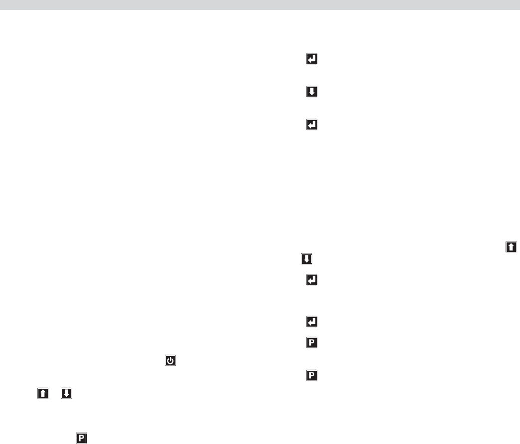
Part # 4526884 Rev 4 (10/08/10) Page 33
CALIBRATION
Bi-Weekly Calibration:
Tools: Digital Pyrometer with Surface Probe
Warning: PERSONAL INJURY FROM BURNS MAY RESULT
WHEN COMING IN CONTACT WITH HOT COOKING
SURFACES.
NOTE: Calibration of grills is done with release material
sheets installed.
NOTE: CALIBRATION REQUIREMENTS
The control software will beep to the user when it is
appropriate to calibrate. The control will allow calibration
provided the following conditions are met:
• Temperature is currently falling from a detected peak
of 360°F or higher.
• Temperature is falling and has fallen 2°F from a
detected peak that is within the 350-360°F range. (i.e.
calibration would be allowed at 355°F if the achieved
peak temperature was 357°F)
• Temperature is rising through the 350-360°F range as a
result of a heat on pulse of less than 30 seconds.
To Calibrate:
1. The upper platens and lower grill plate should be at
operating temperatures to perform this calibration
procedure.
Turn on the Master Switch and press to enter cooking
mode.
2. Press or to select a “CLAM” operation and allow
the grill to reach the set temperature and stabilize,
(approximately 30 minutes).
3. Press and hold for three, (3) seconds. “ENTER CODE” is
displayed.
4. Using the Product buttons, 0-9 enter the code, (1251).
“ENTER CODE **** ” is displayed.
5. Press to enter the Programming Mode.
“PROGRAMMING MODE MENU ITEMS” is displayed.
6. Press three, (3) times. “PROGRAMMING MODE SYSTEM
SETUP” is displayed.
7. Press four, (4) times. “PROBE CAL – UPPER XXXF” is
displayed.
8. Place the surface probe of the digital pyrometer directly
on the probe location, (see diagram on following page).
9. Allow at least 5 seconds for the pyrometer to respond
and stabilize. Note the temperature on the pyrometer.
10. If the temperature on the grill control display does not
match the temperature on the pyrometer, adjust the
temperature on the grill control accordingly using the
and buttons.
11. Press . “PROBE CAL – GRILL XXXF” is displayed.
12. Repeat steps 8 - 10.
13. Press to save the changes.
14. Press to return to “PROGRAMMING MODE SYSTEM
SETUP”
15. Press again to exit.
16. Repeat steps 1 - 15 at each control.
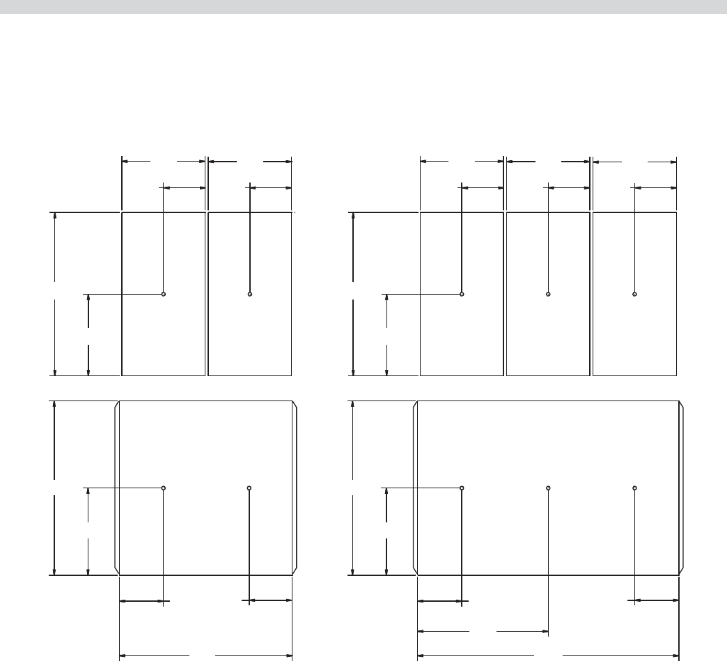
Part # 4526884 Rev 4 (10/08/10)Page 34
Probe Locations:
The grill’s thermocouple probes are located on each section of the lower grill plate in the center of the cooking zone as shown
in the diagram below. Each upper platen has one thermocouple probe in the center.
CALIBRATION continued
TOP
PLATEN
(3 PLACES)
11.5" 11.5"
5.75" 5.75"5.75"
22.5"
24"
12"
6.09"
18"
36"
6.09"
6.09"
11.25"
11.5"
GRILL PLATE
TOP
PLATEN
(2 PLACES)
11.5" 11.5"
5.75"5.75"
2
2.5"
2
4"
12"
6.09"
24"
11.25"
GRILL PLATE
MODEL XG24 MODEL XG36
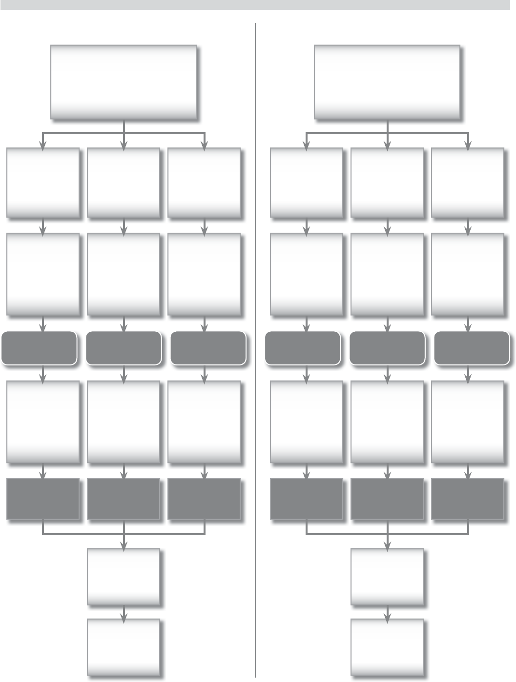
Part # 4526884 Rev 4 (10/08/10) Page 35
ERROR LOGIC & TROUBLESHOOTING
Probe Error Heating Error
Occurs when the probe
is open or not connected.
The controller will turn
the heat o .
Occurs the controller
will fails to detect a
temperature response
over a 6-minute period.
Error
not self-
correcting
Error
not self-
correcting
Press On/
O key to
cancel.
Press On/
O key to
cancel.
Platen
Probe Error
Platen
Heating
Error
Grill
Probe Error
Grill
Heating
Error
Grill &
Platen
Probe
Errors
Grill &
Platen
Heating
Errors
Platen LED
(top) shows
RED &
ashes
Platen LED
(top) shows
RED &
ashes
Grill LED
(bottom)
shows RED
& ashes
Grill LED
(bottom)
shows RED
& ashes
Grill &
Platen LED’s
show RED &
ash
Grill &
Platen LED’s
show RED &
ash
Grill is
operable
only for at
recipes.
Grill is
operable
only for at
recipes.
Grill
is not
operable.
Grill
is not
operable.
Grill
is not
operable.
Grill
is not
operable.
No Audio
Alarm
No Audio
Alarm
Audio
Alarm
Audio
Alarm
Audio
Alarm
Audio
Alarm
L1: PROBE ERROR
L2:
L1: HEATING ERROR
L2:
L1: PROBE ERROR
L2:
L1: HEATING ERROR
L2:
L1:
L2: PROBE ERROR
L1:
L2: HEATING ERROR
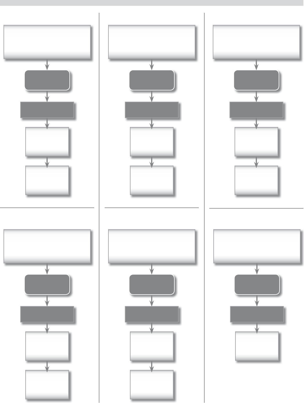
Part # 4526884 Rev 4 (10/08/10)Page 36
ERROR LOGIC & TROUBLESHOOTING continued
Platen Down Error Gas Ignition Error
Occurs when the ignition
feedback signal does not
respond after 4 tries.
Error
not self-
correcting
Press On/
O key to
cancel.
Audio Alarm
L1: IGNITION ERROR
L2:
COMM Error
Occurs when
communication fails between
the main control and the motor
speed controller.
Error
not self-
correcting
Press On/
O key to
cancel.
Audio Alarm
L1: COMM ERROR
L2:
Motor Overcurrent Error
Occurs when current to the motor
exceeds 4.8 amps, typically because
platen movement has encountered
mechanical resistance
Error
not self-
correcting
Press Raise
Button to
cancel.
Audio Alarm
L1: MOTOR
L2: OVERCURRENT
Motor Error
Occurs when the platen is in normal
up or down motion between limits,
but fails to generate 5 encoder
counts in any 1-second interval.
Recycle Main
Power Switch
Audio Alarm
L1: MOTOR
L2: ERROR
Occurs at cycle-start when the
platen fails to reach lower limit
position within 40 sec.
Error
not self-
correcting
Press On/
O key to
cancel.
Audio Alarm
L1: PLATEN DOWN
L2:
Platen Up Error
Occurs at cycle-end when the
platen fails to reach upper limit
position within 40 sec.
Error
not self-
correcting
Press On/
O key to
cancel.
Audio Alarm
L1: PLATEN UP
L2:
Part # 4526884 Rev 4 (10/08/10) Page 37
ERROR LOGIC & TROUBLESHOOTING continued
Motor Error2
Occurs when the platen is in motion
and fails to reach the upper or lower
limit position within 30 seconds,
(150 encoder counts)
Recycle Main
Power Switch
Audio Alarm
L1: MOTOR
L2: ERROR2
Lower Switch Error
Occurs at cycle start when the
lower limit switch fails to signal the
platen’s arrival at the lower limit
position within 200 seconds.
Recycle Main
Power Switch
Audio Alarm
L1: LOWER SWITCH
L2: FAIL
Upper Switch Error
Appears in code,
but is never set.
Recycle Main
Power Switch
Audio Alarm
L1: UPPER SWITCH
L2: FAIL
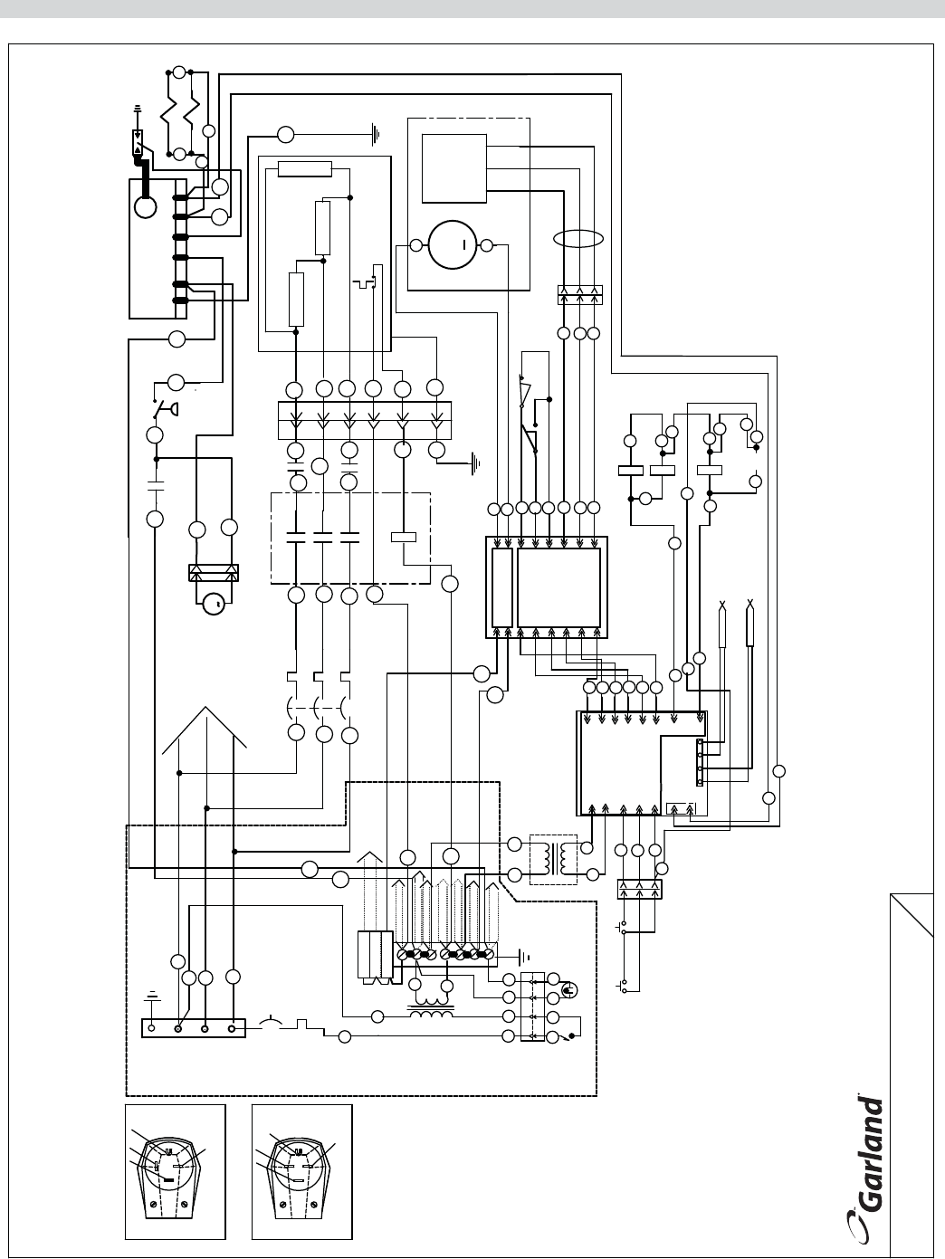
Part # 4526884 Rev 4 (10/08/10)Page 38
WIRING DIAGRAM
FREELAND
PENNSYLVANIA
18224
4520365 R01
DWG:
XG-36
MODEL
1A
24
CIRCUIT BREAKERS
TO OTHER SECTION
S3
STBY SWITCH
RAISE SWITCH
PILOT LAMP
MAIN SWITCH
1
P3
26
5
P4/6
GRIDDLE YELLOW
PLATEN YELL
PLATEN RED
69A
67A
6
J1/
P7/3
P7/2
P7/1
P7S7
P4/5
35
35A
39
38
P4/8
P4/9
33
24V
31
P4/1
P4/3
120V
P4/12
J1/5
J2/1
J2/2
GRIDDLE RED
MAIN CONTROL
J1/8
J1/9
15
P4/15
J1/
4
J1/
45
P4/4
J1/
J1/
13
12
J1/
14
42
P4/13
44
P4/14
43
J1/3
J1/1J1/
10
J1/
11
40
41
P4/11
P4/10
NEMA 15-50P
NEMA 15-30P
SEE CHART FOR PLUG
AND CORD CONFIGURATION.
3
TB1
TB2 120 V DIST.
1265
7
240V
3
4
120V
5A Fuse
5A Fuse
5A Fuse
Z
X
Y
Z
GND
CIRCUIT BREAKER
CONTROL &MOTOR CIRCUITS
1
X
Y
L1A
L2A
MOTOR CIRCUITS
TO OTHER
8A
IGNITION CIRCUITS
TO OTHER
TO OTHER
MOTOR CIRCUITS
CTRL XFMRS
CONTACTORS
TO OTHER
9A
3A
HI-LIMITS
TO OTHER
TO OTHER
IGNITION CIRCUITS
CTRL XFMRS
TO OTHER
4A
TO OTHER
2A
CB PLATEN
65A
61A
L2A
L1A
L3A
XY GND
GND
Z
L3A
NC COMM
UPPER LIMIT SWITCH
P5/1
COMM
35B
LOWER LIMIT SWITCH
-+
THERMOCOUPLE GRIDDLE
-+
THERMOCOUPLE PLATEN
26
26A
26
ELECTRIC ONLY
35A
SSR3 GRIDDLE
35B
35C
J2/12
35A
MOTOR CONTROL
J2/7
J2/10
J2/8
P5/8
P5/9
P5/10
J2/9
P5/6
P5/7
J2/6
J2/4
J2/3
J2/11
J2/2
24
35A
24A
SSR2 PLATEN
35C
35D
SSR1 PLATEN
35D
P5/3
P5/4
P5/12
12
14
P5/2
P5/11
11
52
13
NO
S6
14
12
P6/1
P6/2
13
P6
P6/3
5V
PULSE GROUND
ENCODER
J3/3
J3/4
P2/4
P5/5
P2/3
J2/5
J3/1
J2/1
J3/2
3A
4A
P2/1
P2/2
12A
51
10A
G
5A
8A 6
4
5
CONTACTOR
L2A
L1A
L3A
FAN MOTOR
M
S8/2
S8/1
T3A
T1A
2
T2A
7A
SSR2
3
6A
SSR1
1
63A
66A
S1
5
8
6
44
5
-
10A
MOTOR
M
HI LIMIT
+
12A
1333W
PLATEN HEATERS
2
T2
7
3
16
P1
1333W
1333W
69A
67A
68A
PRESSURE SWITCH
S8
SSR3 GRIDDLE
61A
62A
64A 65A
GT
NS
IGN
V
V
ACTUATOR
G
60A
70A
IGNITER
SOLENOID VALVE
J68 J69
OTHER SECTIONS HAVE THE SAME WIRING DIAGRAM.
NOTE: THIS IS THE DIAGRAM OF ONE SECTION ONLY.
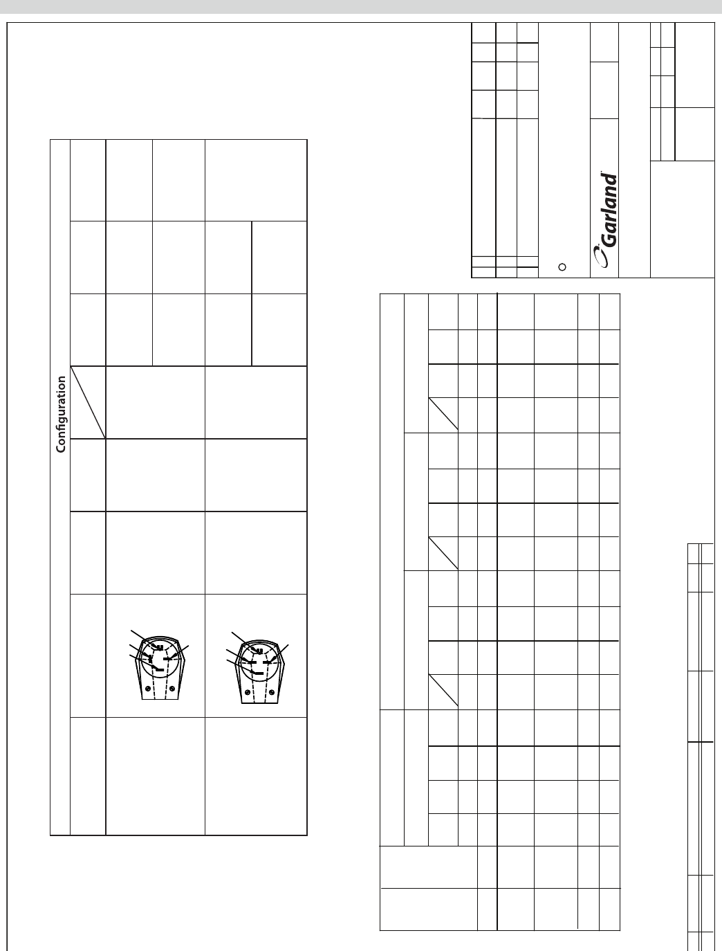
Part # 4526884 Rev 4 (10/08/10) Page 39
XG-36-xxx
05/23/05
THESE DRAWINGS AND SPECIFICATIONS ARE THE PROPERTY OF GARLAND COMMERCIAL INDUSTRIES
2004 GARLAND COMMERCIAL INDUSTRIES
AND SHALL NOT BE COPIED OR REPRODUCED WITHOUT THEIR WRITTEN PERMISSION.
*** CAD PRODUCED DRAWING - DO NOT REVISE MANUALLY ***
C
CHANGE DESCRIPTION
SYM
REV
DOC DATE DR APP
SIZE
SCALE FACTOR
DATE
DR. BY
DR. CK.
APP.
FILE NAME
MODEL(S)
DESCRIPTION
FREELAND
PENNSYLVANIA
18224
TOLERANCE IN INCHES
(ANGULAR ± .5°)
(EXCEPT AS NOTED)
(FLAT .XXX ± .015)(FORM .XXX ± .031)
ADDED GENERAL EXTENSION "xxx"
ADDED PLUG TYPES AND NOTES.
208/220/240
VOLT 60HZ
WIRING DIAGRAM
XG-36
RELEASED ITEM/S
TO INCLUDE DERIVED MODELS
0 -
1 -
*
45203S65 R01
NA D
AJGAJG AJG
323
PCO
2005
5/23
PCO
1632 2008
7/7
AJGAJG
MD
NKA
4520365
PART NUMBER
1
ITEM
WIRING DIAGRAM XG-36 208/220/240
DESCRIPT AMNOI TERIAL
-
BLANK SIZE
- -
FINISH
1
REV
X-N
LOADING KW PER PHASE
TOTAL
8.66
XG-36-F
1.0
L/R
XG-36-1
L/C/R
4.33
XG-36-2
XG36 12.99
MODEL
LOAD
KW
35.38
23.57
11.78
NOMINAL AMPS PER LINE
208V 3PH DELTA
24.93
2.66
2.66 3.33
1.0
1.33 1.66
4.16
1.33 12.46
208/220/240 3PH
4.00 4.99
X-Y X-Z
4.00 37.43
Y-Z X
20.9424.93 23.57
22.14
4.16
12.4611.07
3.9 3.9
10.4711.78
220V 3PH DELTA
37.4333.30
ZY
31.4935.38
X ZY
19.1921.61 21.61
9.59
3.6
10.80
3.6
10.80
240V 3PH DELTA
28.90
32.43
X
32.43
Y Z
Xpress Grill Cord and Plug
P/N Plug Type Cord Gauge
Supplied NEMA Plug Voltage
(3ph Delta)
Maximum
Current
Minimum
Cord Gauge
4525505
Z
GND
YX
4-6AWG 15-50P
208 37 4-6AWG
240 32 4-8AWG
4525508
XGND
Z
Y
4-10AWG 15-30P
208 25
4-10AWG
240 22
WIRING DIAGRAM

Part # 4526884 Rev 4 (10/08/10)Page 40
WIRING DIAGRAM
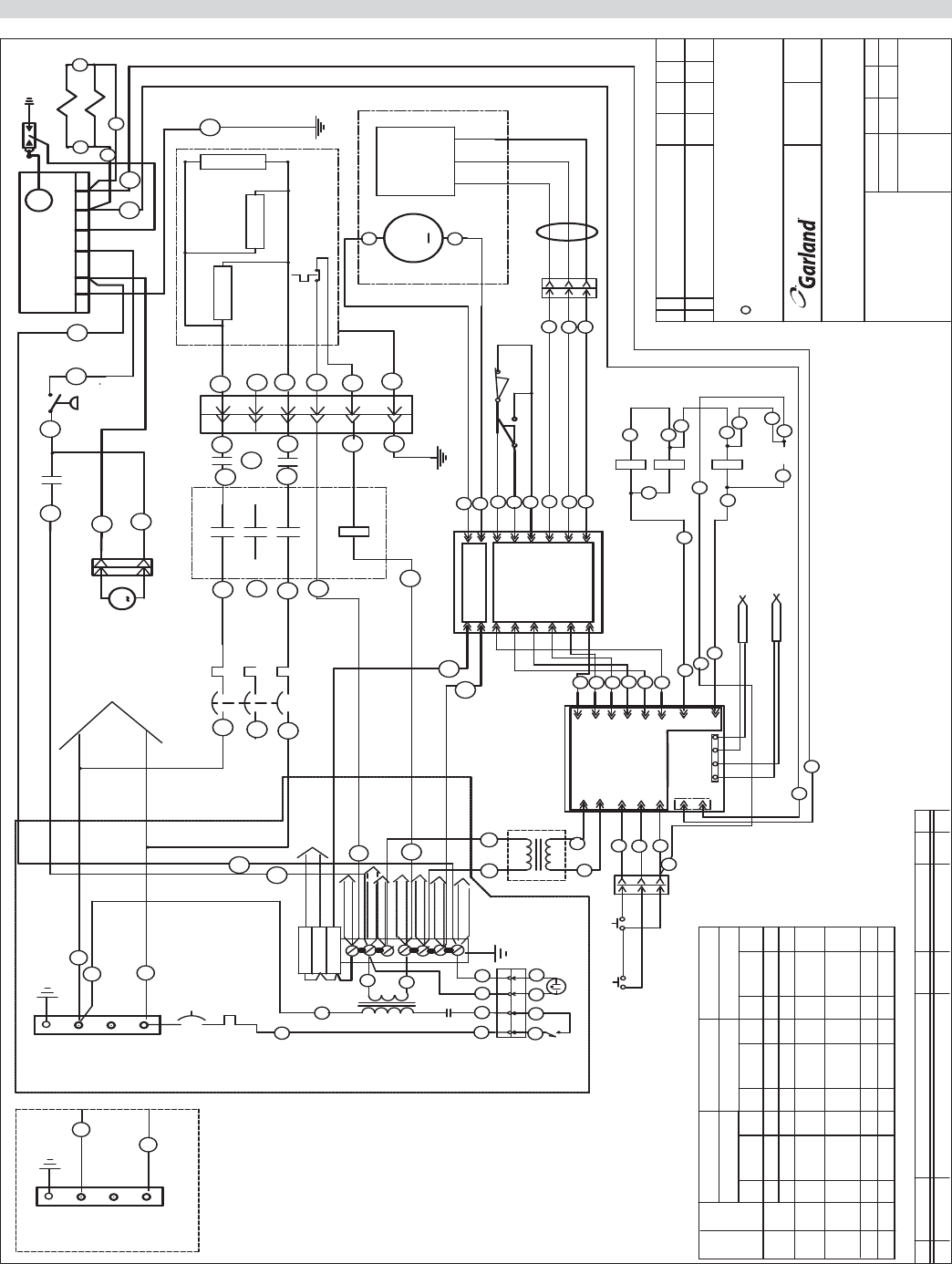
Part # 4526884 Rev 4 (10/08/10) Page 41
WIRING DIAGRAM
THESE DRAWINGS AND SPECIFICATIONS ARE THE PROPERTY OF GARLAND COMMERCIAL INDUSTRIES
2004 GARLAND COMMERCIAL INDUSTRIES
AND SHALL NOT BE COPIED OR REPRODUCED WITHOUT THEIR WRITTEN PERMISSION.
*** CAD PRODUCED DRAWING - DO NOT REVISE MANUALLY ***
C
CHANGE DESCRIPTION
SYM
REV
DOC DATE DR APP
SIZE
SCALE FACTOR
DATE
DR. BY
DR. CK.
APP.
FILE NAMEMODEL(S)
DESCRIPTION
FREELAND
PENNSYLVANIA
18224
TOLERANCE IN INCHES
(ANGULAR ± .5°)
(EXCEPT AS NOTED)
(FLAT .XXX ± .015)(FORM .XXX ± .031)
*RELEASED ITEM/S
NA
0JLBG-PCO
2186
2009
8/18
WIRING DIAGRAM
XG-36
208/220/240V
1 PHASE-60HZ XG36
05/23/05
AJG AJG AJG
4520365-1
4520365-11 WIRING DIAGRAM XG-36 208/220/240V - 1PH - - - 0
D
FAN MOTOR
OTHER SECTIONS HAVE THE SAME WIRING DIAGRAM.
NOTE: THIS IS THE DIAGRAM OF ONE SECTION ONLY.
TO OTHER
PILOT LAMP
MAIN SWITCH
RAISE SWITCH
P3
S3
126
5
1265
MAIN CONTROL
24V
P7/1
P7/2
P7/3
33
STBY SWITCH
P4/5
P4/9
35
39
J1/5
J1/9
P4/8
P4/3
P4/1
38
31
J1/8
J1/3
J1/1
8A
TO OTHER
IGNITION CIRCUITS
TO OTHER
MOTOR CIRCUITS
CTRL XFMRS
9A
120V
P4/15
P4/14
P4/13
P4/12
P4/11
P4/10
13
15
J1/
14
J1/
J1/
12
J1/
J1/
11
10
J1/
45
44
43
42
41
40 J2/10
P5/10
P5/9
P5/8
J2/9
2A
P5/6
P5/7
J2/8
J2/7
P5/5
J2/6
J2/5
P2/4
1A
P2/3
J3/3
J3/4
TB2 120 V DIST.
L3A
5A Fuse
5A Fuse
5A Fuse
CONTROL &MOTOR CIRCUITS
CIRCUIT BREAKER
X
L1A
1
240V
120V
7
4
3
TB1
Y
E
3
61A
HI-LIMITS
IGNITION CIRCUITS
TO OTHER
TO OTHER
CTRL XFMRS
TO OTHER
CONTACTORS
TO OTHER
3A
4A
TO OTHER
MOTOR CIRCUITS
65A
CB PLATEN
L1A
L2A
L3A
CIRCUIT BREAKER
TO B SECTION
MOTOR
M
5V
PULSE
GROUND
ENCODER
ACTUATOR
LOWER LIMIT SWITCH
35D
SSR1 PLATEN
P5/3
P5/12
P5/4
MOTOR CONTROL
J2/12
J2/4
24A
12
14
P2/1
P2/2
P5/11
P5/2
P5/1
J2/3
J2/11
J2/2
J2/1
J3/1
J3/2
13
11
52
51
NO
10A
12A
G
P6/1
P6/2
12
14
NC
COMM
UPPER LIMIT SWITCH
COMM
P6/3
13
S6P6
-
10A
HI LIMIT
PLATEN HEATERS
63A
T1A
3A
4A
L1A
5A
8A
7A
CONTACTOR
L2A
L3A T3A
T2A
SSR2
6A
SSR1
3
37
5
66 8
55
444
1
1
2
2
T2
6
S1 P1
1333W
62A
66A
61A
S8
M
S8/2
S8/1
SSR3 GRIDDLE
64A
PRESSURE SWITCH
65A
NG
12A
+
G
1333W
60A
1333W
IGNITER
67A 69A
TS
IGN
V
V
70A
68A
J68
SOLENOID VALVE
J69
-+
THERMOCOUPLE PLATEN
-+
THERMOCOUPLE GRIDDLE
NOMINAL AMPS
TOTAL
LOAD
12.99
MODEL 208 1PH
KW
TB L1/L3
GRIDDLE YELLOW
GRIDDLE RED
PLATEN YELL
PLATEN RED
67A
J2/2
P4/6
J1/
6
26
35A
35A
S7 P7
69A
J2/1 P4/4
J1/
4
24
SSR2 PLATEN
35A
35C
26A
ELECTRIC ONLY
SSR3 GRIDDLE
26
35A
35B
35B
35D
24
35C
XG36-2
L/R
XG36-1
L/C/R
XG36-F
8.66 41.63
4.33 20.82
1.0 1.5 1.5
39.36
19.68
NOMINAL AMPS
L1/L3
220 1PH
1.5
18.04
NOMINAL AMPS
L1/L3
240 1PH
1
2
1
1
1
XG36 18.04
36.0841.63 39.36
20.82
19.68
36.08
X
TB2
Y
E
L1C
L3C
TB2 USED WITH XG-36
STANDARD ( 3 PLATENS )
WW
SECTION "C"
AND C SECTION ON
ON 1 AND 2 PLATEN GRILLS
REVFINISHBLANK SIZEMATERIALDESCRIPTIONPART NUMBERITEM