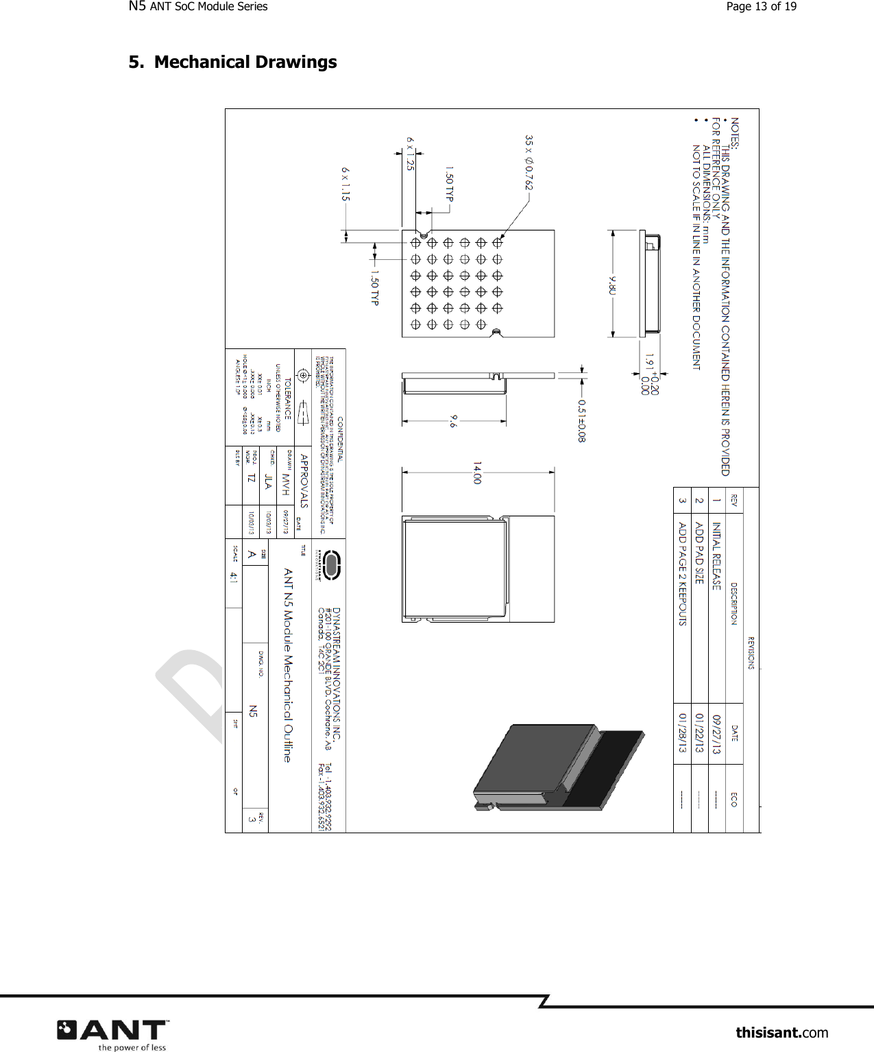
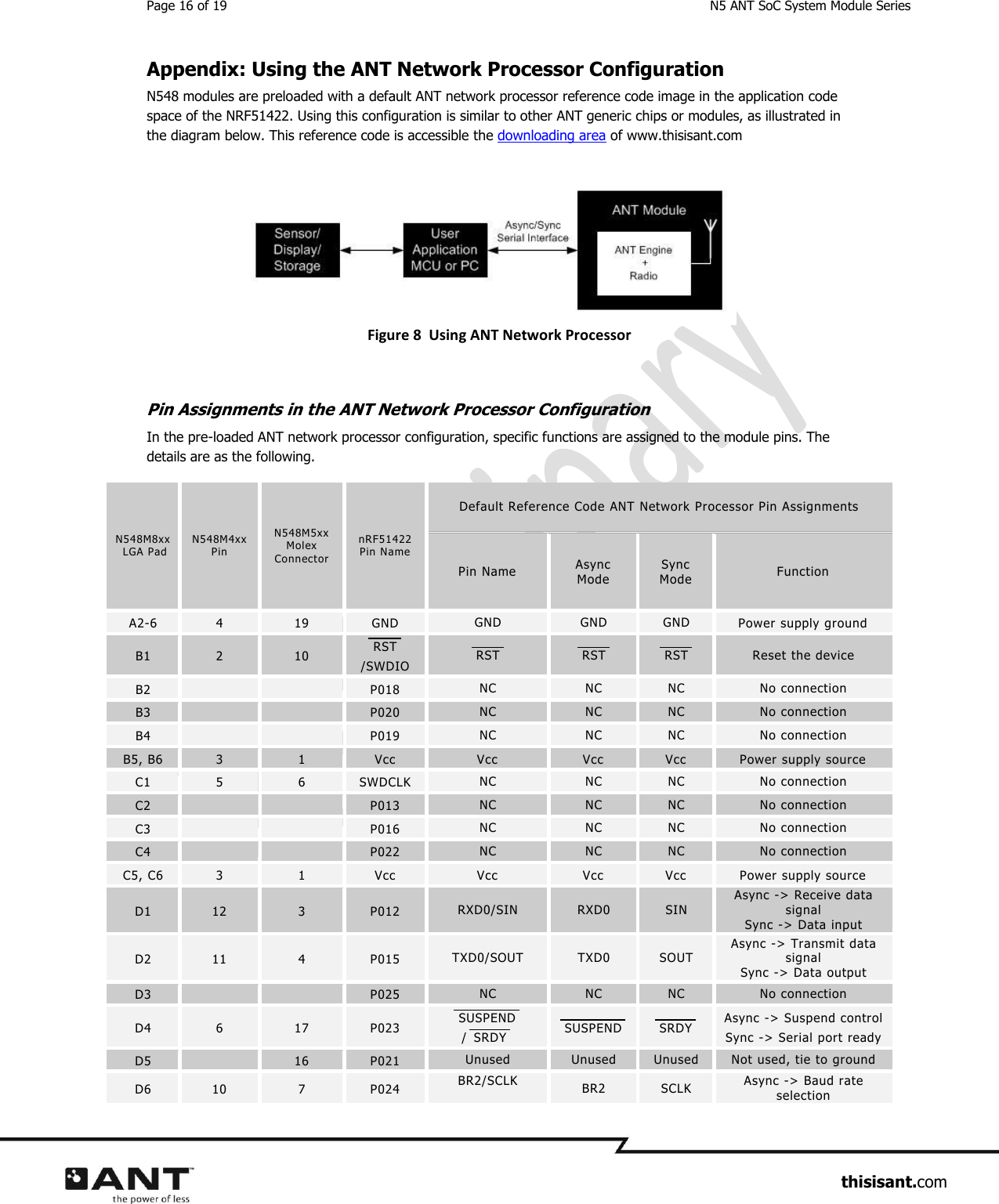
Garmin Canada 2398 N5 User Manual ANT Doc Title

DynaStream Innovations Inc. N5 ANT Doc Title

User Manual

 D00001598  Rev 0.70  N5 ANT SoC Module Series ANT Operation (when loaded with S210 SoftDevice)   79 selectable RF channels (2402 to 2480 MHz)  Simple to complex network topologies:  peer-to-peer, star, tree, star-to-star and more  Broadcast, acknowledged, and burst data communication modes  Supports up to 8 logical channels each with configurable channel periods (5.2ms – 2s)  Built-in device search and pairing  Built-in interference handling and radio coexistence management with application radio disable requests and application flash write/erase requests  Enhanced ANT features - Advanced burst data transfer modes (up to 60kbps)  - Optional single channel encryption mode (AES-128) - Supports up to 8 public, private and/o r managed networks - Advanced power management features to optimize application power consumption including Event Filtering and Selective data updates - Asynchronous transmit channel - Fast channel initiation ANT/BLUETOOTH® low energy peripheral Operation (when loaded with S310 SoftDevice)   ANT operation functions as S210  BLUETOOTH 4.0 compliant low energy single-mode protocol stack - Link Layer - L2GAP,ATT, and SM protocols - GATT,GAP, and L2GAP - Peripheral and Broadcaster roles - GATT Client and Server - Full SMP support including MITM and OOB pairing   Module Hardware  Integrated PCB meander antenna  Onboard 32kHz and 16MHz crystal clocks   1.8V to 3.6V supply voltage range  -25°C to +75°C operating temperature  24 GPIOs (LGA package)  Programmable output per channel from –20dBm up to +4dBm  Excellent receiver sensitivity -90dBm  RSSI reading (1dBm resolution)  Total 256kB embedded flash memory and 16kB RAM  SPI, I2C and UART interface  ARM SWD interface  14.0x9.8x2.0mm (LGA package)  Drop-in compatible package with AP2/C7 modules  Radio regulatory approval for major markets  BLUETOOTH SIG qualification  RoHS compliant  FAMILY MEMBERS (N5xx Mxxx) ANTN548 – pre-loaded with ANT Stack and network processor code - M8CB:  14x9.8mm LGA  - M4CB:  20x20mm SMT - M5CB:  20x20mm Molex connector
Page 2 of 19  N5 ANT SoC System Module Series                     thisisant.com Table of Contents 1. N5 System Module Series ............................................................................................................................. 4 1.1 N5 Module Nomenclature ................................................................................................................ 4 1.2 N5 System Module Offerings ........................................................................................................... 4 1.3 Production Code ............................................................................................................................. 5 2. Product Overview .......................................................................................................................................... 6 2.1 Block diagram ................................................................................................................................. 6 2.2 Generic Pin-outs ............................................................................................................................. 6 2.3 Writing the application code and programming ................................................................................. 7 2.4 Designs Consideration using the Module .......................................................................................... 8 2.5 Assembly Consideration................................................................................................................... 8 2.6 Moisture Control ............................................................................................................................. 8 3. Regulatory Approvals and Compliances ....................................................................................................10 3.1 United States ................................................................................................................................ 10 3.2 Industry Canada Compliance ......................................................................................................... 10 3.3 CE Declaration of Conformity ......................................................................................................... 11 3.4 Australia & New Zealand ............................................................................................................... 11 3.5 Japan ........................................................................................................................................... 11 3.6 BLUETOOTH Qualification .............................................................................................................. 11 4. Electrical Specifications ..............................................................................................................................12 4.1 Absolute Maximum Ratings (1) ........................................................................................................ 12 4.2 Recommended Operating Conditions ............................................................................................. 12 4.3 Electrical Specifications ................................................................................................................. 12 5. Mechanical Drawings  .................................................................................................................................13 6. Support ........................................................................................................................................................14 6.1 One Year Limited Warranty ........................................................................................................... 14 6.2 ANT Forum ................................................................................................................................... 14 6.3 Public Technical References ........................................................................................................... 14 6.4 ANT Developer’s Zone ................................................................................................................... 15 6.5 ANT Social Media .......................................................................................................................... 15 Appendix: Using the ANT Network Processor Configuration ...........................................................................16 Pin Assignments in the ANT Network Processor Configuration ........................................................... 16 Async Mode Baud Rate Select .......................................................................................................... 17 Async Mode Baud Connection Example ............................................................................................ 18 Byte Sync Mode Connection Example ............................................................................................... 19
N5 ANT SoC Module Series  Page 3 of 19                     thisisant.com Notices and Restricted Use Information Information contained in this document is provided only for your ("Customer" or “you”) convenience and may be superseded by updates. It is your responsibility to ensure that your application meets with your specifications. Dynastream Innovations Inc. ("DYNASTREAM") makes no representations or warranties of any kind whether express or implied, written or oral, statutory or otherwise, related to the information, including but not limited to its condition, quality, performance, merchantability or fitness for purpose. DYNASTREAM disclaims all liability arising from this information and its use. DYNASTEAM does not assume any responsibility for the use of the described ANT module (“the Module(s)”). Dynastream makes no representation with respect to the adequacy of the module in low-power wireless data communications applications or systems. Any Products using the Module must be designed so that a loss of communications due to radio interference or otherwise will not endanger either people or property, and will not cause the loss of valuable data. DYNASTREAM assumes no liability for the performance of products which are designed or created using the Modules.  The Modules are not designed, intended, or authorized for use as components in systems intended for surgical implant into the body, or other applications intended to support or sustain life, or for any other application in which the failure of the Module could create a situation where personal injury or death may occur. If you use the Modules for such unintended and unauthorized applications, you do so at your own risk and you shall indemnify and hold DYNASTREAM and its officers, employees, subsidiaries, affiliates, and distributors harmless against all claims, costs, damages, and expenses, and reasonable attorney fees arising out of, directly or indirectly, any claim of personal injury or death associated with such unintended or unauthorized use, even if such claim alleges that DYNASTREAM was negligent regarding the design or manufacture of the Product. The information disclosed herein is the exclusive property of DYNASTREAM, and is not to be reproduced and/or distributed without the written consent of DYNASTREAM. No part of this publication may be reproduced or transmitted in any form or by any means including electronic storage, reproduction, execution or transmission without the prior written consent of DYNASTREAM. The recipient of this document by its retention and use agrees to respect the security status of the information contained herein. DYNASTREAM believes the information contained herein is correct and accurate at the time of its release. However, the information contained in this document is subject to change without notice and should not be construed as a commitment by DYNASTREAM unless such commitment is expressly given in a covering document. ©2013 Dynastream Innovations Inc. All Rights Reserved. ANT is a registered trade mark of Dynastream Innovations Inc.
Page 4 of 19  N5 ANT SoC System Module Series                     thisisant.com 1. N5 System Module Series The N5 module series uses Nordic Semiconductor’s nRF51422, the industry’s first System on Chip (SoC) solution that is able to support ANT standalone or ANT/BLUETOOTH low energy dual mode operation depending on the loaded protocol stack with advantages in power, size, cost, speed and security built directly into the protocol layer. The nRF51422 integrates a 32-bit ARM® Cortex™ M0 CPU with 256KB flash, 16KB RAM, and analog and digital peripherals. Benefits will reach consumers in the form of new products with even longer battery life, expanded functionality and security, further simplified operation and overall value.  Nordic Semiconductor protocol stacks are known as SoftDevices. SoftDevices are pre-compiled, pre-linked binary files, which can be programmed and are downloadable from the Nordic Semiconductor’s web. The nRF51422 and N5 system module series support the S210, ANT 8-channel protocol stack, and the S310, ANT 8-channel / BLUETOOTH low energy peripheral protocol stack.   The N5 system module series starts with N548M8CB (or ANTN548M8CB) in a 14.0mm x 9.8mm x 2.0mm LGA (Land Array Grid) package. A compact design meeting the industrial requirement to go small, light and wearable, the N548M8CB is also a turnkey system hardware solution including antenna, onboard 32k and 16M crystal clock, DC-DC converter and 24 GPIOs with 6 analogue inputs. The N548M8CB modules are pre-programmed with the S210 SoftDevice and reference ANT network processor application code in order to function as a generic ANT RF module when connected to an application controller. Both pre-programmed images can be easily replaced via the onboard SWD interface pins using off-the-shelf ARM programmers. Pin compatible options to Dynastream’s 20mm x 20mm AP2 or C7 modules are also available. In these options, N548M8CB modules are soldered on carrier boards that are pin compatible to the previous modules. Current AP2 or C7 module customers can easily use these models to evaluate the hardware and upgrade their final products.    The N5 module series if loaded with ANT and/or BLUETOOTH Low energy stack has been certified to comply with radio regulation or standards covering major markets include North America, Europe, Australia, New Zealand and Japan. The N5 modules series is also qualified by the BLUETOOTH SIG.  1.1  N5 Module Nomenclature   1.2 N5 System Module Offerings The N5 module series are currently available in the following varieties.    Module  Description  Packaging  and O rdering Opti ons  N548M8CB  Or  ANTN548M8CB 14.0 x 9.8 x 2.0mm, LGA package, 31 pins, 24 GPIOs. Pre-loaded with S210 SoftDevice and ANT network processor code.  ANTN548M8CB-Tray:  40 modules on a tray N548M8CB-Reel: 1500 modules tap ed on a 13”  reel     N548M4CB  Or  ANTN548M4CB 20.0 x 20.0mm, 17 p ins, 13 GPIOs . Pre-loaded with  S210 SoftDevice and ANT network processor code. ANTN548M4CB-Tray:  20 modules on a tray ANTN548M4CB-Reel: 800 mod ules tap ed on a 13”  reel   N548M5CB   Or 20.0 x 20.0mm, 20 pin Molex connector. Onboard  JTAG programming connector. 13 ANTN548M5CB-Tray:  20 modules on a tray
N5 ANT SoC Module Series  Page 5 of 19                     thisisant.com ANTN548M5CB  GPIOs. Pre-loaded with S210 SoftD evice and ANT network processor code.  Table 1 N5 Module Series Offerings 1.3 Production Code For technical support and customer service purposes, a production code of three characters is laser marked on the RF shield as illustrated below.   Figure 1 N5 Module Production Code  YW – Production date code R – Product version
Page 6 of 19  N5 ANT SoC System Module Series                     thisisant.com 2. Product Overview 2.1 Block diagram Figure 2 N5 Module Series Block Diagram 2.2 Generic Pin-outs Figure 3 N5xy M8__ Module LGA Bottom View  Figure 4 N5xy M4__ Bottom View
N5 ANT SoC Module Series  Page 7 of 19                     thisisant.com Figure 5 N5xy M5__ Bottom View N5xy M8xx  LGA Pad N5xy M4xx Pin N5xy M5xx Molex Connector nRF51422  Pin Name Description A2-6 4 19 GND Power supply ground B1 2 10 RST/SWDIO System reset. Also HW debug and flash programming I/O B2   P018 GPIO B3   P020 GPIO B4   P019 GPIO B5, B6 3 1 Vcc Power supply source C1 5 6 SWDCLK HW debug and flash programming I/O C2   P013 GPIO C3   P016 GPIO C4   P022 GPIO C5, C6 3 1 Vcc Power supply source D1 12 3 P012 GPIO D2 11 4 P015 GPIO D3   P025 GPIO D4 6 17 P023 GPIO D5  16 P021 GPIO D6 10 7 P024 GPIO E1 14 9 P009 GPIO E2 15 14 P011 GPIO E3 13 5 P006 GPIO / ADC input 7/ ADC reference voltage 1 E4  20 P004 GPIO / ADC input 5 E5 9 11 P000 GPIO / ADC reference voltage 0 E6 8 13 P030 GPIO F1 16 12 P008 GPIO F2 17 2 P005 GPIO / ADC input 6 F3 1 8 P003 GPIO / ADC input 4 F4  18 P001 GPIO / ADC input 2 F5 7 15 P002 GPIO / ADC input 3 F6   P031 GPIO Table 2 N5 Module Generic Pin-Outs 2.3 Writing the application code and programming Please refer to nRF51422 S210 SoftDevice Specification or nRF51422 S310 SoftDevice Specification from Nordic Semiconductor.
Page 8 of 19  N5 ANT SoC System Module Series                     thisisant.com 2.4 Designs Consideration using the Module The M8 module is designed to show the best RF performance in general with FR4 PCB attached. Typical radiation pattern is as follows,       Figure 6 Typical Radiation Pattern Please refer to the following drawing to mount the module. Figure 7 Antenna Keep Out and PCB note 2.5  Assembly Consideration 2.6 Moisture Control  The moisture control of the module is rated at level 1 defined by IPC/JEDEC J-STD-020. The modules do not require special storage conditions provided:  They are maintained at conditions equal to or less than 30 °C/85 % RH, and
N5 ANT SoC Module Series  Page 9 of 19                     thisisant.com  They are solder reflowed at a peak body temperature which does not exceed 260 °C To ensure good solderability of the PCB pads, it is highly recommended to always have the modules intended for reflow well sealed when in storage.
Page 10 of 19  N5 ANT SoC System Module Series                     thisisant.com 3. Regulatory Approvals and Compliances The N5 system module series has received regulatory approvals in the United States (FCC) and Canada (IC), and has been verified to conform to the appropriate regulations in Europe, Australia and New Zealand, and Japan. The module series has been qualified by BLUETOOTH SIG. Such approvals and qualification allow the user to place the module inside a finished product and, in most cases, not require regulatory testing for an intentional radiator, provided no changes or modifications are made to the module circuitry. This does not preclude the possibility that some other form of authorization or testing may be required for the finished product. Changes or modifications could void the user’s authority to operate the equipment. The end user must comply with all of the instructions provided by the Grantee, which indicate installation and/or operating conditions necessary for compliance. 3.1 United States The N5 system module series has been tested and found to comply with the limits for a Class B digital device, pursuant to Part 15 of the FCC Rules.  These limits are designed to provide reasonable protection against harmful interference in a residential installation.  This equipment generates, uses, and can radiate radio frequency energy and, if not installed and used in accordance with the instructions, may cause harmful interference to radio communications.  However, there is no guarantee that interference will not occur in a particular installation.  If this equipment does cause harmful interference to radio or television reception, which can be determined by turning the equipment off and on, the user is encouraged to try to correct the interference by one of the following measures: - Reorient or relocate the receiving antenna. - Increase the separation between the equipment and receiver. - Connect the equipment into an outlet on a circuit different from that to which the receiver is connected. - Consult the dealer or an experienced radio/TV technician for help. The N5 module series complies with Part 15 of the FCC Rules.  Operation is subject to the following two conditions: (1) This device may not cause harmful interference, and (2) this device must accept any interference received, including interference that may cause undesired operation. The N5 module series does not contain any user-serviceable parts. Unauthorized repairs or modifications could result in permanent damage to the equipment, and void your warranty and your authority to operate this device under Part 15 regulations. The N5 module series is labelled with its own FCC ID, O6R2398 (note: First Character is the letter O, not the # 0.) If the FCC ID is not visible when the module is installed inside another device, then the outside of the device into which the module is installed must also display a label referring to the enclosed module. This exterior label can use wording such as the following: “Contains Transmitter Module FCC ID: O6R2398” or “Contains FCC ID: O6R2398”. Any similar wording that expresses the same meaning may be used. 3.2 Industry Canada Compliance The N5 system module series complies with Industry Canada licence-exempt RSS standard(s).  Operation is subject to the following two conditions: (1) this device may not cause interference, and (2) this device must accept any interference, including interference that may cause undesired operation of the device. (Le présent appareil est conforme aux CNR d'Industrie Canada applicables aux appareils radio exempts de licence.  L'exploitation est autorisée aux deux conditions suivantes : (1) l'appareil ne doit pas produire de brouillage, et (2) l'utilisateur de l'appareil doit accepter tout brouillage radioélectrique subi, même si le brouillage est susceptible d'en compromettre le fonctionnement.)
N5 ANT SoC Module Series  Page 11 of 19                     thisisant.com To comply with Industry Canada regulations, it is required that product containing the N5 module series display a label referring to the enclosed module.  This exterior label can use wording similar to the following: “Contains IC:  3797A-2398”  This information shall be affixed in such a manner as not to be removable except by destruction or defacement. The size of the lettering shall be legible without the aid of magnification but is not required to be larger than 8-point font size. If the device is too small to meet this condition, the information can be included in the user manual upon agreement with Industry Canada. 3.3 CE Declaration of Conformity  The N5 system module series is declared to be in conformance with the essential requirements and other relevant provisions of Directive 1999/5/EC and 2011/65/EU, as a low-powered unlicensed transmitter:  EN 60950-1:2006+A11:2009+A1:2010+A12:2011 Information technology equipment - Safety - Part 1: General requirements  EN 300 440-2 v1.4.1 Electromagnetic compatibility and Radio spectrum Matters (ERM); Short range devices; Radio equipment to be used in the 1 GHz to 40 GHz frequency range; Part 2: Harmonized EN covering the essential requirements of article 3.2 of the R&TTE Directive   EN 61000-6-1:2007 Electromagnetic compatibility (EMC) -- Part 6-1: Generic standards - Immunity for residential, commercial and light-industrial environments  EN 301 489-3 V1.6.1 Electromagnetic compatibility and Radio spectrum Matters (ERM); Electromagnetic Compatibility (EMC); standard for radio equipment and services; Part 3: Specific conditions for Short-Range Devices (SRD) operating on frequencies between 9 kHz and 40 GHz 3.4 Australia & New Zealand  The N5 system module series has been tested and found to comply with   AS/NZS 4268:2012 Radio equipment and systems – Short range devices  AS/NZS CISPR 22:2009 Information technology equipment - Radio disturbance characteristics - Limits and methods of measurement  The ACMA/MED supplier code number is N20233  3.5 Japan  The N5 system module series has been granted type certificate (mark number R203-JN6049).  Standard applied: Notification No. 88 of MIC 2004, 2.4GHz band wide-band low-power data communication system (item 19 of Article 2 paragraph 1) 3.6 BLUETOOTH Qualification Contents to be added
Page 12 of 19  N5 ANT SoC System Module Series                     thisisant.com 4.  Electrical Specifications  4.1 Absolute Maximum Ratings (1) PARAMETER TEST CONDITIONS Min Max Unit Supply voltage (VCC) All supply pins must have the same voltage -0.3 3.6 V Voltage on any digital pin  -0.3 VCC+0.3, ≤ 3.9 V Storage temperature range  -40 125 °C ESD All pads, according to human-body model, JEDEC STD 22, method A114  4 kV According to charged-device model, JEDEC STD 22, method C101  500 V  (1) Stresses beyond those listed under Absolute Maximum Ratings may cause permanent damage to the device. These are stress ratings only and functional operation of the device at these or any other conditions beyond those indicated under Recommended Operating Conditions is not implied. Exposure to absolute-maximum-rated conditions for extended periods may affect device reliability. 4.2 Recommended Operating Conditions Over operating free-air temperature range (unless otherwise noted) PARAMETER Min Max Unit Operating ambient temperature range, TA -25 +75 °C Operating supply voltage 1.8 3.6 V  4.3 Electrical Specifications Please refer to the nRF51422 Product Specification of Nordic Semiconductor.
N5 ANT SoC Module Series  Page 13 of 19                     thisisant.com 5. Mechanical Drawings
Page 14 of 19  N5 ANT SoC System Module Series                     thisisant.com 6. Support The N5 system module series uses nRF51422 from Nordic Semiconductor. Users can seek technical support, esp. about hardware, from Nordic Semiconductor, www.nordicsemi.com. Users can seek application support from Dynastream Innovations, www.thisisant.com. 6.1 One Year Limited Warranty This product is warranted to be free from defects in materials or workmanship for 1 year from the date of purchase of the end customer. Within this period, Dynastream Innovations Inc. (Dynastream) will, at its sole option, replace any products that fail in normal use. Such replacement will be made at no charge to distributors or companies who purchase this product directly from Dynastream, provided the distributor or company shall be responsible for any transportation cost.  This warranty does not apply to: (i) cosmetic damage, such as scratches, nicks and dents; (ii) damage caused by accident, abuse, misuse, water, flood, fire, or other acts of nature or external causes; (iii) damage caused by service performed by anyone who is not an authorized service provider of Dynastream; (iv) damage to a product that has been modified or altered without the written permission of Dynastream. In addition, Dynastream reserves the right to refuse warranty claims against products or services that are obtained and/or used in contravention of the laws of any country. Replaced products have 1 year warranty as stipulated in this term. THE WARRANTIES AND REMEDIES CONTAINED HEREIN ARE EXCLUSIVE AND IN LIEU OF ALL OTHER WARRANTIES EXPRESS, IMPLIED, OR STATUTORY, INCLUDING ANY LIABILITY ARISING UNDER ANY WARRANTY OF MERCHANTABILITY OR FITNESS FOR A PARTICULAR PURPOSE, STATUTORY OR OTHERWISE.  IN NO EVENT SHALL DYNASTREAM BE LIABLE FOR ANY INCIDENTAL, SPECIAL, INDIRECT, OR CONSEQUENTIAL DAMAGES, WHETHER RESULTING FROM THE USE, MISUSE, OR INABILITY TO USE THIS PRODUCT OR FROM DEFECTS IN THE PRODUCT.  Dynastream retains the exclusive right to replace (with a new or newly-overhauled replacement product) the device or software or offer a full refund of the purchase price at its sole discretion. SUCH REMEDY SHALL BE THE SOLE AND EXCLUSIVE REMEDY FOR ANY BREACH OF WARRANTY. To obtain warranty service, the distributor or company shall contact Dynastream for shipping instructions and a return material authorization (RMA) tracking number. Securely pack the device and a copy of the original sales receipt, which is required as the proof of purchase for warranty claims. Write the tracking number clearly on the outside of the package. Send the device, freight charges prepaid, to Dynastream. 6.2 ANT Forum Users are encouraged to participate in the ANT forum moderated by the application engineering team of Dynastream Innovations for any engineering discussions. Joining the ANT forum is free and open at http://www.thisisant.com/forum. 6.3 Public Technical References Documents: 1. nRF51422 Product Specification, Nordic semiconductor 2. nRF51822 and nRF51422 Product Anomaly Notification (PAN-028), Nordic Semiconductor 3. nRF51422 S210 SoftDevice Specification, Nordic Semiconductor 4. nRF51422 S310 SoftDevice Specification, Nordic Semiconductor 5. ANT Message Protocol and Usage, Dynastream Innovations 6. Interfacing with ANT General Purpose Chipsets and Modules, Dynastream Innovations  Software: 7. S210 nRF51422 SoftDevice
N5 ANT SoC Module Series  Page 15 of 19                     thisisant.com 8. S310 nRF51422 SoftDevice 9. ANT network processor reference code 10. ANTwareII – a system testing and debugging tool  The above documents and software are available at www.thisisant.com and/or ww.nordicsemi.com.   6.4 ANT Developer’s Zone ANT development software tools, application notes, reference designs and other public resources are found in the ANT developer’s zone at http://www.thisisant.com/developer.  To begin development with the ANT+ interoperability, please become an ANT+ Adopter or ANT+ Alliance member to obtain the access to the ANT+ Adopter Zone. ANT+ documents and design tools contained in the ANT+ Adopter zone include the ANT+ Device Profiles, ANT-FS specification, ANT software (PC/Mac) libraries with source code, and embedded reference designs with source code.  6.5 ANT Social Media ANT is on the following social media sites, YouTube: http://www.youtube.com/user/ANTAlliance Twitter: http://twitter.com/ANTPlus Facebook: https://www.facebook.com/thisisant LinkedIn: http://www.linkedin.com/groups?gid=1379137
Page 16 of 19  N5 ANT SoC System Module Series                     thisisant.com Appendix: Using the ANT Network Processor Configuration N548 modules are preloaded with a default ANT network processor reference code image in the application code space of the NRF51422. Using this configuration is similar to other ANT generic chips or modules, as illustrated in the diagram below. This reference code is accessible the downloading area of www.thisisant.com  Figure 8  Using ANT Network Processor   Pin Assignments in the ANT Network Processor Configuration In the pre-loaded ANT network processor configuration, specific functions are assigned to the module pins. The details are as the following.  N548M8xx   LGA Pad  N548M4xx Pin  N548M5xx  Molex Connector nRF51422  Pin Name Default Reference Code ANT Network Processor Pin Assignments Pin Name Async Mode Sync Mode Function A2-6 4 19 GND GND GND GND Power supply ground B1 2 10 RST/SWDIO RST  RST  RST  Reset the device B2   P018 NC NC NC No connection B3   P020 NC NC NC No connection B4   P019 NC NC NC No connection B5, B6 3 1 Vcc Vcc Vcc Vcc Power supply source C1 5 6 SWDCLK NC NC NC No connection C2   P013 NC NC NC No connection C3   P016 NC NC NC No connection C4   P022 NC NC NC No connection C5, C6 3 1 Vcc Vcc Vcc Vcc Power supply source D1 12 3 P012 RXD0/SIN RXD0 SIN Async -> Receive data signal Sync -> Data input D2 11 4 P015 TXD0/SOUT TXD0 SOUT Async -> Transmit data signal Sync -> Data output D3   P025 NC NC NC No connection D4 6 17 P023 SUSPEND/ SRDY  SUSPEND  SRDY  Async -> Suspend control Sync -> Serial port ready D5  16 P021 Unused Unused Unused Not used, tie to ground D6 10 7 P024 BR2/SCLK  BR2 SCLK Async -> Baud rate selection
N5 ANT SoC Module Series  Page 17 of 19                     thisisant.com N548M8xx   LGA Pad  N548M4xx Pin  N548M5xx  Molex Connector nRF51422  Pin Name Default Reference Code ANT Network Processor Pin Assignments Pin Name Async Mode Sync Mode Function Sync -> Clock output signal E1 14 9 P009 BR3 BR3 Tie to GND Async -> Baud rate selection Sync -> Not used, tie to ground E2 15 14 P011 Unused Tie to GND Tie to GND Not used, tie to ground E3 13 5 P006 BR1 BR1 Tie to GND Async -> Baud rate selection Sync -> Not used, tie to ground E4  20 P004 Unused Unused Unused Not used, tie to ground E5 9 11 P000 PORTSEL Tie to GND Tie to VCC Asynchronous or synchronous port select E6 8 13 P030 Unused Tie to GND Tie to GND Tie to GND F1 16 12 P008 Unused Tie to GND Tie to GND Tie to GND F2 17 2 P005 RTS/SEN RTS SEN Async -> Request to send Sync -> Serial enable signal F3 1 8 P003 Unused Unused Unused Not used, tie to ground F4  18 P001 Unused Unused Unused Not used, tie to ground F5 7 15 P002 SLEEP/ MRDY   SLEEP MRDY   Async -> Sleep mode enable Sync -> Message ready indication F6   P031 NC NC NC No connection Table 3 Pin Assignments in ANT Network Processor Configuration Async Mode Baud Rate Select The baud rate of the asynchronous communication is controlled by the speed select signals BR1, BR2 and BR3. Please refer to the table below. BR3 BR2 BR1 Baud Rate 0 0 0 4800 1 0 1 9600 0 1 0 19200 0 0 1 38400 1 1 1 57600 Table 4 Async Mode Baud Rate Select
Page 18 of 19  N5 ANT SoC System Module Series                     thisisant.com Async Mode Baud Connection Example   Notes:  Module RXD and TXD connected directly to hardware USART of microcontroller.   Switches on baud rate selection pins (BR1, BR2 and BR3) are for ease of use only. They can be connected directly to the logic level of interest.  RTS is hardware controlled on the N548 and will toggle on a per byte level. If HW flow control is not available on MCU, the software implemented flow control must be able to manage serial communication flow control on a per byte level.
N5 ANT SoC Module Series  Page 19 of 19                     thisisant.com Byte Sync Mode Connection Example  Notes:  Module SOUT, SIN, and SCLK connected directly to hardware USART of microcontroller.   S E N needs to be on an interrupt capable I/O pin on the microcontroller.  (Interrupt pins located on Port 1&2 on the MSP430F1232)

Navigation menu