Garmin Canada 3067 Low Power Transmitter 2402-2480 MHz User Manual
DynaStream Innovations Inc. Low Power Transmitter 2402-2480 MHz Users Manual
UserManual.wiki
>
Garmin Canada
>
3067 User Manual
Users Manual
Navigation menu
Upload a User Manual
Namespaces
Wiki Guide
HTML
PDF
Info
Views
User Manual
Discussion / Help
Navigation
![D52Q ANT Module Part of the D52 Module Series from Dynastream Innovations ANT® Operation (using the latest s212 or s332 SoftDevice) 79 selectable RF channels (2402 to 2480 MHz) (preliminary) Flexible network topologies: peer-to-peer, star, tree, high node count, mesh and more Broadcast, acknowledged, and burst data communication modes Built-in device search and pairing Built-in interference handling and radio coexistence management with application radio disable requests and application flash write/erase requests Enhanced ANT features: o Supports up to 15 logical channels each with configurable channel periods (5.2ms - 2s) o Advanced burst data transfer modes (up to 60kbps) o Optional channel encryption mode (aes-128) o Supports up to 8 public, private and/or managed networks o Advanced power management features to optimize application power consumption including Event Filtering and Selective Data Updates o Asynchronous transmit channel o Fast channel initiation ANT/Bluetooth® Smart operation (when loaded with the latest s3XX soft-device) ANT operation functions as S212 Bluetooth 4.2 compliant low energy single-mode protocol stack suitable for Bluetooth Smart products o Concurrent Central, Observer, Peripheral, and Broadcaster roles with up to: Multiple connections as a central One connection as a peripheral Observer Broadcaster o Link layer o L2CAP, ATT, and SM protocols o GATT and GAP APIs o GATT Client and Server [future: module picture] Module Hardware 20 x 20 x 2.7mm module using the nRF52832 chip from Nordic Semiconductor in two SKUs: o D52QD2M4IA – Module o D52QD2M4IA-A – Module + accelerometer o Layout compatible with N5 M4, AP2, C7 o Additional LGA pads for extended nRF52 features Integrated printed antenna On-board 32.768 kHz and 32 MHz crystal clocks Supply Voltage range: o 1.7V to 3.6V o 1.71V to 3.6V when using accelerometer Internal DC/DC converter supported Operating temperature: Industrial (-40°C to +85°C) 29 GPIOs o 23 GPIOs for accelerometer SKU Programmable output per channel from -20dBm up to 4dBm Excellent receiver sensitivity o –92.5dBm ANT mode o –96.5dBm BLE mode 1dBm resolution RSSI Total 512kB flash, 64kB RAM SPI, I2C and UART interface ARM SWD interface Available onboard ST LIS2DH accelerometer o 3-axis MEMS accelerometer o 2 programmable interrupt pins Radio regulatory approval for major markets (engineering samples are provided pre-certification) BLUETOOTH SIG qualification RoHS compliant D00001675 D52Q ANT Module OEM/Integrators Installation Manual / Data sheet Rev 0.4](https://usermanual.wiki/Garmin-Canada/3067/User-Guide-3016220-Page-1.png)
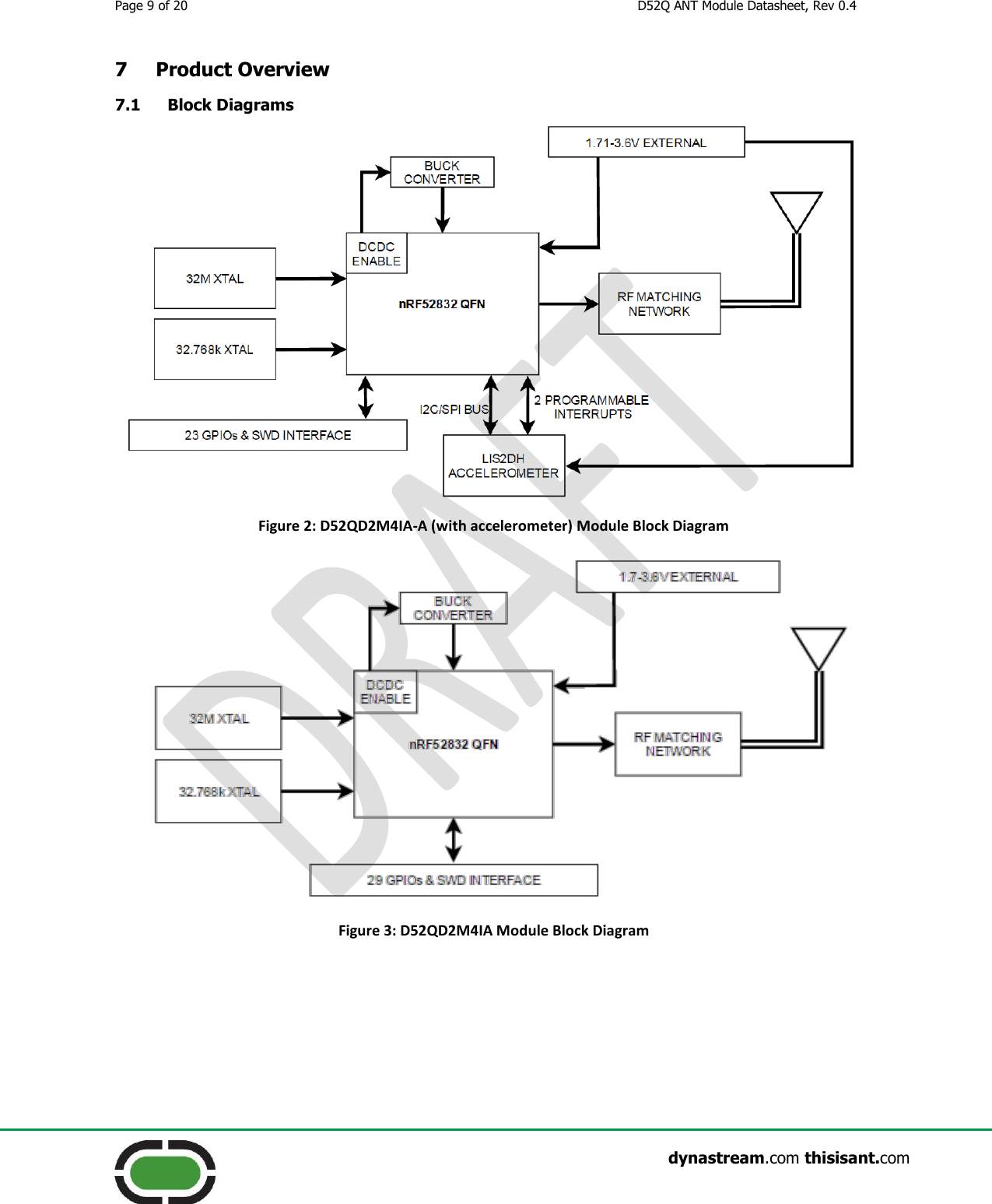
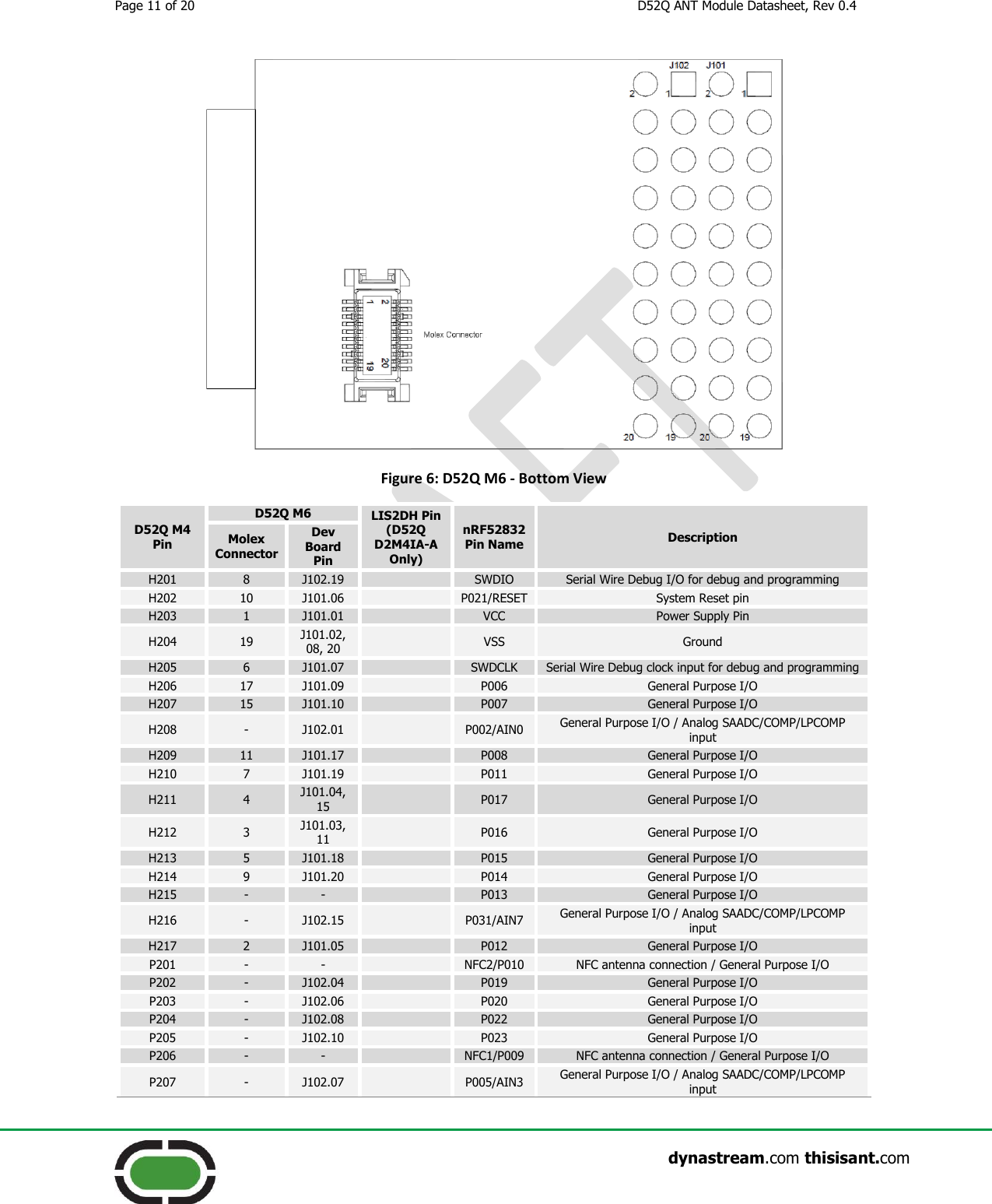
![Page 12 of 20 D52Q ANT Module Datasheet, Rev 0.4 dynastream.com thisisant.com D52Q M4 Pin D52Q M6 LIS2DH Pin (D52Q D2M4IA-A Only) nRF52832 Pin Name Description Molex Connector Dev Board Pin P208 - J102.02 P018 General Purpose I/O P209 - J102.12 P024 General Purpose I/O P210 - J102.05 P004/AIN2 General Purpose I/O / Analog SAADC/COMP/LPCOMP input P211 - J102.03 P003/AIN1 General Purpose I/O / Analog SAADC/COMP/LPCOMP input P212 - J102.16 INT2 P026 General Purpose I/O P213 - J102.11 SDA/SDI/SDO P029/AIN5 General Purpose I/O / Analog SAADC/COMP/LPCOMP input P214 - J102.13 SCL/SPC P030/AIN6 General Purpose I/O / Analog SAADC/COMP/LPCOMP input P215 - J102.09 SDO/SA0 P028/AIN4 General Purpose I/O / Analog SAADC/COMP/LPCOMP input P216 - J102.18 CS P027 General Purpose I/O P217 - J102.14 INT1 P025 General Purpose I/O Table 3 - D52 Module Series Pin-Out 7.3 (Optional) Accelerometer Specification The D52Q module family supports an accelerometer accessory on the D52QD2M4IA-A. The accelerometer is the LIS2DH by STMicroelectronics. To make use of the accelerometer, the following pins are consumed: D52QD2M4IA-A Pin nRF52832 Pin LISD2H Pin P212 P026 INT2 P213 P029/AIN5 SDA/SDI/SDO P214 P030/AIN6 SCL/SPC P215 P028/AIN4 SDO/SA0 P216 P027 CS P217 P025 INT1 Table 4: Accelerometer Pin Assignment SPI or I2C can be used to communicate with the accelerometer. To use I2C, pull-up resistors will need to be added to the appropriate pads. For more information about D52Q pin assignments, refer to Table 3 - D52 Module Series Pin-Out. For more information about this component including data sheet and errata, please refer to the STMicroelectronics website: http://www.st.com/web/en/catalog/sense_power/FM89/SC444/PF252928. 7.4 Preloaded Software The D52Q module is preloaded with the S212 SoftDevice and the ANT Network Processor (NP) code as illustrated below. Depending on the module revision, the preloaded code versions vary. Please refer to Appendix C for further details. S212 SoftDevice developed by and available from Dynastream – [nRF52832 S212 SoftDevice full specification will be available for product release]](https://usermanual.wiki/Garmin-Canada/3067/User-Guide-3016220-Page-12.png)