Garmin 0037600 Aviation Transponder User Manual 327sec123
Garmin International Inc Aviation Transponder 327sec123
UserManual.wiki
>
Garmin
>
0037600 User Manual
Users Manual
Navigation menu
Upload a User Manual
Namespaces
Wiki Guide
HTML
PDF
Info
Views
User Manual
Discussion / Help
Navigation
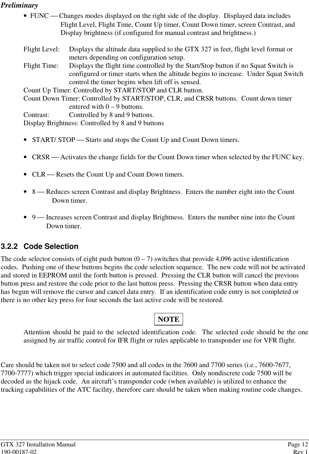
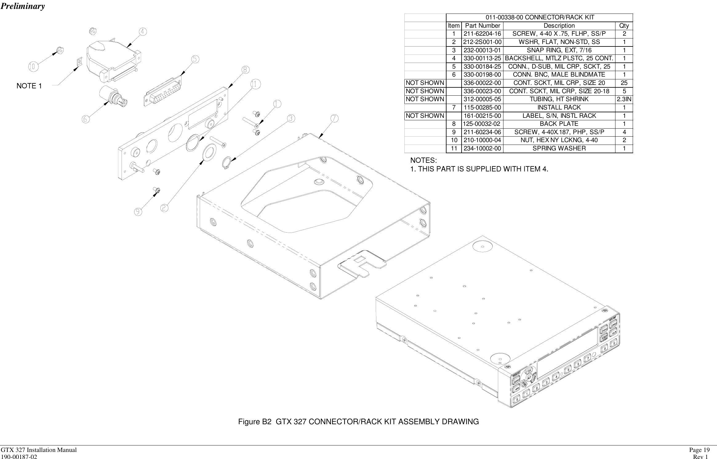
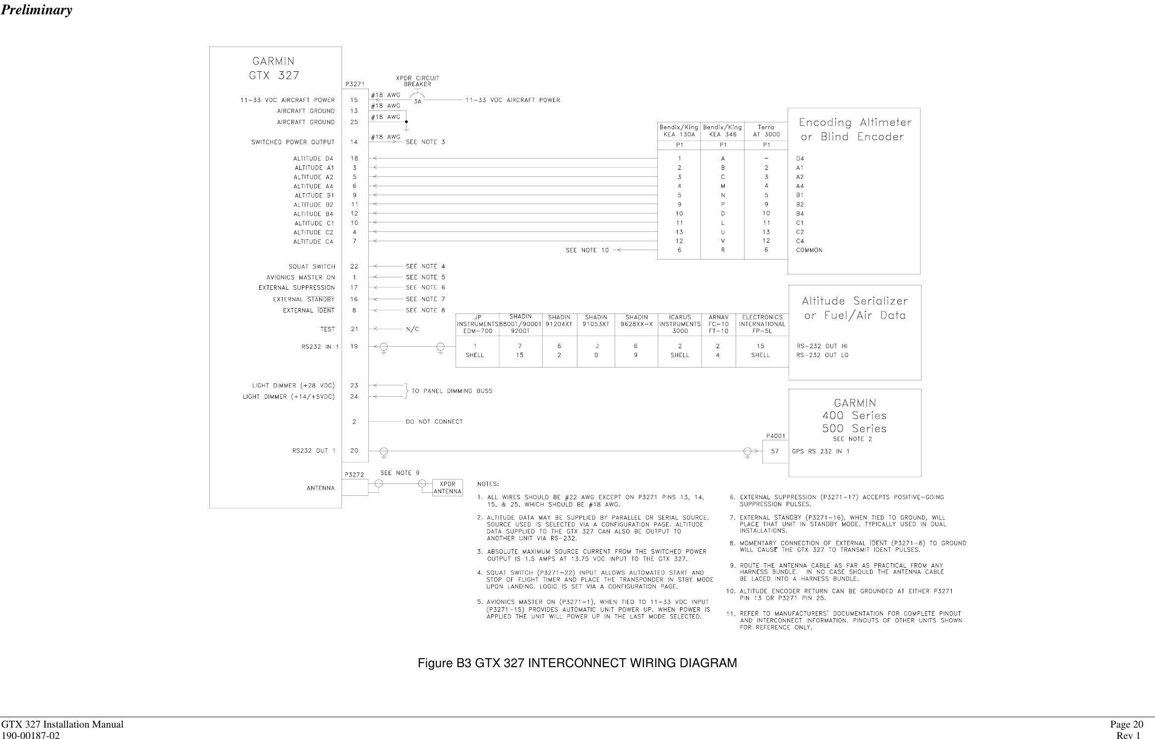
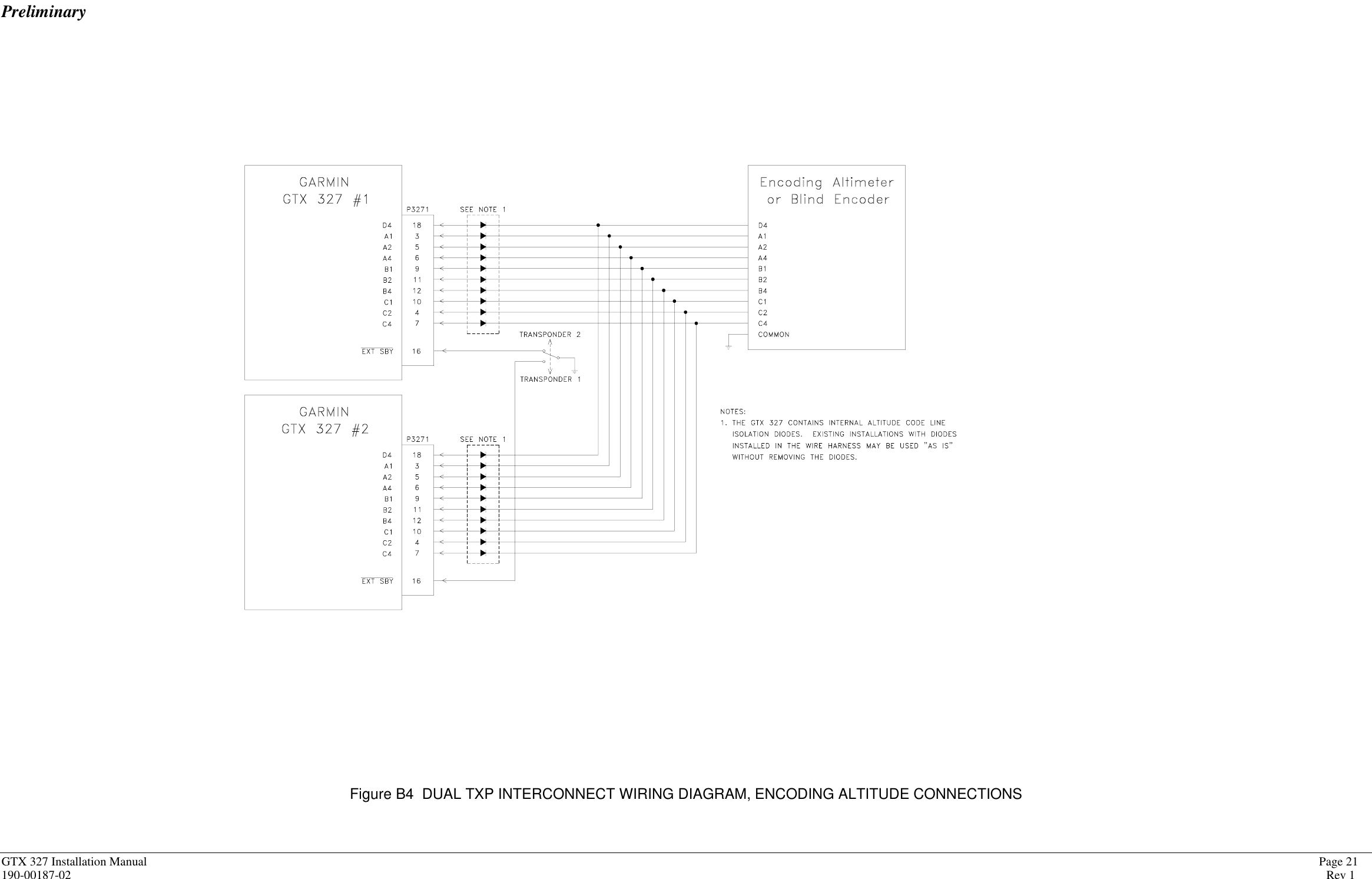
![PreliminaryGTX 327 Installation Manual Page 13190-00187-02 Rev 13.2.3 Configuration PagesHolding down the CRSR button and pressing the ON button provides access to the configuration pages. TheFUNC button will sequence through the configuration pages. The CRSR button will highlight selectablefields on each page. When a field is highlighted, numeric data entry will be performed with the 0-9 buttons,and list selections will be performed with the 8 or 9 buttons. Changes made through the configuration pagesare stored in EEPROM memory.• Display Backlight PageCurrent display backlight intensity: displayed valueSelect manual or automatic backlight sourceAutomatic backlight source: Select automatic backlight source (Photocell, 28Vdc, 5Vdc)Display backlight filter response time: Select display backlight response time (3-7) (default to 4)Display backlight filter slope: Select display backlight filter slope value (0-99) (default to 50)Display backlight filter minimum value: Select display minimum filter slope value (0-99) (default to 50)Display backlight filter offset: Select display backlight filter offset value (0-99) (default to 50)• Key Backlight PageCurrent key backlight intensity: Displayed valueAutomatic key backlight source: Select automatic key backlight source (Photocell, 28Vdc, 5Vdc)Key backlight filter response time: Select key backlight response time (3-7) (default to 4)Key backlight filter slope: Select key backlight filter slope value (0-99) (default to 50)Key backlight filter minimum value: Select key minimum filter slope value (0-99) (default to 50)Key backlight filter offset: Select key backlight filter offset value (0-99) (default to 50)• Contrast Configuration PageSelect contrast mode (Auto, Manual) (default, to Auto)Select contrast offset (0 to99) (default, to 50)• Operation Configuration Page #1VFR identification code: Enter the VFR identification code (default 1200)Altitude Input source: Select the altitude input source [Gray code(default), Icarus, Shadin]Altitude display format: Select altitude display format [Flight level (default), Feet, Meters]Aircraft climb rate: Enter aircraft climb rate [100 to 2000 fpm (500 fpm default)]• Operation Configuration Page #2SQUAT SWITCH senseAutomatic STBY operation enabledAutomatic STBY delay duration• Gray Code Input Configuration PageGray Code discretesGray Code altitude• Discrete Input Configuration PageEXTERNAL IDENT input:EXTERNAL STANDBY input:SQUAT SWITCH input: On ground equals High or Low](https://usermanual.wiki/Garmin/0037600/User-Guide-72552-Page-18.png)