Garmin 0037600 Aviation Transponder User Manual 327sec123
Garmin International Inc Aviation Transponder 327sec123
Garmin >
Users Manual
Preliminary
GTX 327 INSTALLATION MANUAL
GARMIN Corporation
1200 E. 151st Street
Olathe, KS 66062
Dwg. Number 190-00187-02 Rev. 1
Archive Filename: 190-00187-02-01.zip
Document Source: MS Word
Rev. Date Description of Change ECO #
1 10/07/99 Engineering Release ---
Confidential
This document and the specifications contained herein
are the property of GARMIN Corporation and may not
be reproduced or used in whole or in part as the basis
for manufacturing or sale of products without written
permission of GARMIN Corporation.
Approvals Date
Drawn MD 10/07/99
Chkd.
Proj. Mgr.
Released
Preliminary
GARMIN International, Inc.
1200 E. 151st Street
Olathe, KS 66062 USA
190-00187-02 Revision 1
October 1999
*7;
,167$//$7,21
0$18$/

Preliminary
GTX 327 Installation Manual Page A
190-00187-02 Rev 1
© Copyright 1999
GARMIN Corporation
All Rights Reserved
Except as expressly provided below, no part of this manual may be reproduced, copied, transmitted,
disseminated, downloaded or stored in any storage medium, for any purpose without the express prior
written consent of GARMIN Corporation. GARMIN Corporation hereby grants permission to download a
single copy of this manual and of any revision to this manual onto a hard drive or other electronic storage
medium to be viewed and to print one copy of this manual or of any revision hereto, provided that such
electronic or printed copy of this manual or revision must contain the complete text of this copyright notice
and provided further that any unauthorized commercial distribution of this manual or any revision hereto is
strictly prohibited. GARMIN International, Inc.
1200 E. 151st Street
Olathe, KS 66062 USA
Telephone: 913-397-8200
Dealer Line: 1-800-800-1420
Web Site Address: www.garmin.com
RECORD OF REVISIONS
Revision Revision
Date Description ECO #
1 10/07/99 Engineering Release ----

Preliminary
GTX 327 Installation Manual Page i
190-00187-02 Rev 1
TABLE OF CONTENTS
1. GENERAL DESCRIPTION................................................................................................................. 1
1.1 INTRODUCTION................................................................................................................................ 1
1.2 EQUIPMENT DESCRIPTION ............................................................................................................ 1
1.3 INTERFACE SUMMARY................................................................................................................... 1
1.4 GTX 327 TRANSPONDER SPECIFICATIONS ................................................................................ 2
1.5 EQUIPMENT AVAILABLE ............................................................................................................... 2
1.6 INSTALLATION ACCESSORIES...................................................................................................... 3
1.7 ADDITIONAL EQUIPMENT REQUIRED ........................................................................................ 3
1.8 INSTALLATION APPROVAL ........................................................................................................... 3
1.9 LIMITED WARRANTY...................................................................................................................... 4
2. INSTALLATION ................................................................................................................................. 5
2.1 INTRODUCTION................................................................................................................................ 5
2.2 UNPACKING AND INSPECTING EQUIPMENT............................................................................. 5
2.3 ANTENNA INSTALLATION............................................................................................................. 5
2.3.1 Location Considerations ........................................................................................................... 5
2.3.2 Antenna Installation.................................................................................................................. 5
2.3.3 Antenna Cable Installation........................................................................................................ 6
2.3.4 Antenna Cable Connectors........................................................................................................ 6
2.4 GTX 327 INSTALLATION................................................................................................................. 8
2.5 COOLING AIR..................................................................................................................................... 8
2.6 ELECTRICAL CONNECTIONS......................................................................................................... 8
3 POST INSTALLATION CONFIGURATION & CHECKOUT PROCEDURE ............................... 10
3.1 AIRCRAFT STATION LICENSING REQUIREMENTS................................................................. 10
3.2 OPERATION...................................................................................................................................... 10
3.2.1 Function Selection Switch ...................................................................................................... 11
3.2.2 Code Selection ........................................................................................................................ 12
3.2.3 Configuration Pages................................................................................................................ 13
APPENDIX A. CERTIFICATION DOCUMENTS................................................................................... 14
A.1 CONTINUED AIRWORTHINESS.................................................................................................... 14
A.2 ENVIRONMENTAL QUALIFICATION FORM.............................................................................. 15

Preliminary
GTX 327 Installation Manual Page ii
190-00187-02 Rev 1
APPENDIX B. ASSEMBLY AND INSTALLATION DRAWINGS........................................................ 17
B-1 GTX 327 OUTLINE DRAWING ......................................................................................................18
B-2 GTX 327 CONNECTOR/RACK KIT ASSEMBLY DRAWING ..................................................... 19
B-3 GTX 327 INTERCONNECT WIRING DIAGRAM.......................................................................... 20
B-4 DUAL TXP INTERCONNECT WIRING DIAGRAM,
ENCODING ALTITUDE CONNECTIONS...................................................................................... 21
APPENDIX C. STC PERMISSION........................................................................................................... 22

Preliminary
GTX 327 Installation Manual Page 1
190-00187-02 Rev 1
1. GENERAL DESCRIPTION
1.1 INTRODUCTION
This manual provides the installation and operating instructions for the GARMIN GTX 327 Digital Display
Transponder system. Information pertaining to the maintenance, alignment, and procurement of replacement
parts is found in the GTX 327 Maintenance Manual, P/N 190-00187-05.
1.2 EQUIPMENT DESCRIPTION
The GARMIN GTX 327 is a panel-mounted transponder with the addition of timing functions. The
transponder is a radio transmitter and receiver that operates on radar frequencies, receiving ground radar
interrogations at 1030 MHz and transmitting a coded response of pulses to ground-based radar on a
frequency of 1090 MHz.
As with other Mode A/Mode C transponders, the GTX 327 replies with any one of 4,096 codes, which differ
in the position and number of pulses transmitted. By replying to ground transmissions, the GTX 327 enables
ATC to display aircraft identification, altitude and groundspeed on ATC radar screens. The GTX 327 is
equipped with IDENT capability that activates the Special Position Identification (SPI) pulse for 18 seconds.
The GTX 327 is configured with all key controls. The layout of the front panel keys and displays segregates
the transponder’s primary functions from the secondary timing functions. The unit can be configured so the
aircraft avionics master bus can turn the unit on.
1.3 INTERFACE SUMMARY
The GTX 327 provides the following interface connections via the rear connector:
• Ten (10) encoding altimeter inputs.
• External IDENT input.
• External STBY input.
• External suppression pulse input.
• Switched power output of up to 1.5 amps (for digital altitude encoder power).
• Aircraft power input (11 to 33 volts).
• Aircraft dimming buss input voltage.
• Aircraft master switch turn-on option.
• Serial altitude input.
• Serial altitude output.

Preliminary
GTX 327 Installation Manual Page 2
190-00187-02 Rev 1
1.4 GTX 327 TRANSPONDER SPECIFICATIONS
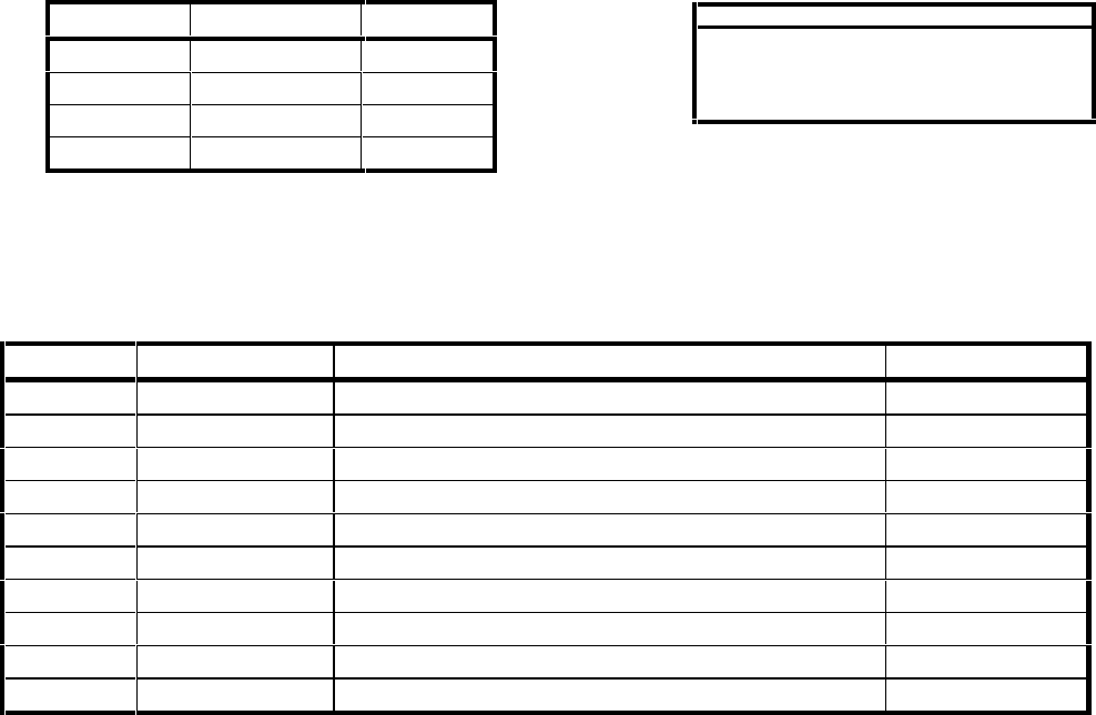
SPECIFICATION CHARACTERISTIC
TSO, JTSO C74c Class 1A
TSO ENV CAT Refer to appendix A
Applicable Documents FAA TSO C74c; RTCA DO-160C
Temperature Range -20°C to +55°C (Continuous Operation)
GTX 327 Unit Weight 1.60 lbs.
GTX 327 Rack Weight 0.64 lbs.
Power Requirements 11.0 to 33.0 Vdc; Max Power Input: 12 Watts
Humidity 95% @ +55°C for 16 Hours; 85% @ +38°C for 32 Hours
Altitude 50,000 Feet
Transmitter Frequency 1090 MHz
Transmitter Power 125 Watts minimum, 150 Watts nominal at the unit antenna
port
Receiver Frequency 1030 MHz
Receiver Sensitivity -72dBm Nominal for 90% replies
Mode A Capability 4096 Identification Codes
Mode C Capability 100 Foot Increments from -1000 to 63,000 feet
External Suppression Input Low ≤ 0.5V; High ≥ 8V
1.5 EQUIPMENT AVAILABLE
ITEM GARMIN P/N
GARMIN GTX 327 Transponder 010-00188-00
GARMIN GTX 327 Transponder, includes GARMIN installation kit,
P/N 010-10216-00 010-00188-01
GARMIN GTX 327 Installation kit 010-10216-00
GARMIN GTX 327 Antenna kit 010-10160-00

Preliminary
GTX 327 Installation Manual Page 3
190-00187-02 Rev 1
1.6 INSTALLATION ACCESSORIES
The following installation accessories are available:
•GARMIN GTX 327 Installation Kit, P/N 010-10216-00 containing Connector/Rack Kit,
P/N 011-00338-00 (see figure B-2 for connector/rack kit assembly drawing).
•GARMIN GTX 327 Antenna Kit, P/N 010-10160-00. Note: A transponder antenna approved to TSO
C66( ) or C74( ) that has been installed to meet the requirements of this manual may be approved for
use with the GTX 327.
1.7 ADDITIONAL EQUIPMENT REQUIRED
•Antenna Sealant - Use antenna manufacturer’s instructions, install according to FAA AC 43.13-2A.
•Cables - The installer will supply all system cables. Cable requirements and fabrication is detailed in
Section 2 of this manual.
•Hardware - #6 Flat Head Screw (6 ea.) and #6-32 Self-Locking Nut (6 ea.). Hardware required to
mount installation rack is not provided.
•Encoding Altitude Digitizer - Use encoding altimeter manufacturer’s instructions, install according to
FAA AC 43.13-2A.
1.8 INSTALLATION APPROVAL
The conditions and tests required for TSO approval of the GTX 327 Transponder and antenna are minimum
performance standards. It is the responsibility of those desiring to install this transponder and antenna either
on or within a specific type or class of aircraft to determine that the aircraft installation standards are within
the TSO standards. The GTX 327 and antenna may be installed only if further evaluation by the applicant
documents an acceptable installation and is approved by the administrator. For GTX 327 TSO compliance,
see Appendix A. For antenna TSO compliance, refer to antenna manufacturer’s literature.

Preliminary
GTX 327 Installation Manual Page 4
190-00187-02 Rev 1
1.9 LIMITED WARRANTY
GARMIN Corporation warrants this product to be free from defects in materials and manufacture for
one year from the date of purchase. GARMIN will, at its sole option, repair or replace any
components that fail in normal use. Such repairs or replacement will be made at no charge to the
customer for parts or labor. The customer is, however, responsible for any transportation costs. This
warranty does not cover failures due to abuse, misuse, accident or unauthorized alteration or repairs.
THE WARRANTIES AND REMEDIES CONTAINED HEREIN ARE EXCLUSIVE AND IN
LIEU OF ALL OTHER WARRANTIES EXPRESS OR IMPLIED OR STATUTORY,
INCLUDING ANY LIABILITY ARISING UNDER ANY WARRANTY OF
MERCHANTABILITY OR FITNESS FOR A PARTICULAR PURPOSE, STATUTORY OR
OTHERWISE. THIS WARRANTY GIVES YOU SPECIFIC LEGAL RIGHTS, WHICH MAY
VARY FROM STATE TO STATE.
IN NO EVENT SHALL GARMIN BE LIABLE FOR ANY INCIDENTAL, SPECIAL, INDIRECT
OR CONSEQUENTIAL DAMAGES, WHETHER RESULTING FROM THE USE, MISUSE, OR
INABILITY TO USE THIS PRODUCT OR FROM DEFECTS IN THE PRODUCT. SOME
STATES DO NOT ALLOW THE EXCLUSION OF INCIDENTAL OR CONSEQUENTIAL
DAMAGES, SO THE ABOVE LIMITATIONS MAY NOT APPLY TO YOU.
To obtain warranty service, call the GARMIN Customer Service department (913-397-8200) for a
returned merchandise tracking number. The unit should be securely packaged with the tracking
number clearly marked on the outside of the package and sent freight prepaid and insured to a
GARMIN warranty service station. A copy of the original sales receipt is required as the proof of
purchase for warranty repairs. GARMIN retains the exclusive right to repair or replace the unit or
software or offer a full refund of the purchase price at its sole discretion. SUCH REMEDY SHALL
BE YOUR SOLE AND EXCLUSIVE REMEDY FOR ANY BREACH OF WARRANTY.

Preliminary
GTX 327 Installation Manual Page 5
190-00187-02 Rev 1
2. INSTALLATION
2.1 INTRODUCTION
This section provides the necessary information for the installing the GTX 327 Transponder, and where
required, optional accessories. Installation of the GTX 327 will differ according to equipment location and
other factors. Cabling will be fabricated by the installing agency to fit these various requirements. This
section contains interconnect diagrams, mounting dimensions, and information pertaining to installation.
Any deviations from the installation instructions prescribed in this document shall be accomplished in
accordance with the requirements set forth in FAA AC 43.13-2A.
2.2 UNPACKING AND INSPECTING EQUIPMENT
Carefully unpack the equipment and make a visual inspection of the unit for evidence of damage incurred
during shipment. If the unit is damaged, notify the carrier and file a claim. To justify a claim, save the
original shipping container and all packing materials. Do not return the unit to GARMIN until the carrier has
authorized the claim.
Retain the original shipping containers for storage. If the original containers are not available, a separate
cardboard container should be prepared that is large enough to accommodate sufficient packing material to
prevent movement.
2.3 ANTENNA INSTALLATION
2.3.1 Location Considerations
A. The antenna (GARMIN P/N 010-10160-00) should be well removed from any major
protrusions, such as engine(s), propeller(s), and antenna masts. It should also be as far as
practical from landing gear doors, access doors, or other openings that could effect its
radiation pattern.
B. The antenna should be mounted on the underside of the aircraft and in a vertical position
when the aircraft is in level flight.
C. Avoid mounting the antenna within three feet of the ADF sense antenna or any other
communication antenna and six feet from the DME antenna.
D. To prevent RF interference, the antenna must be physically mounted a minimum distance of
three feet from the GTX 327.
NOTE
If the antenna is being installed on a composite aircraft, ground planes must sometimes be
added. Conductive wire mesh, radials, or thin aluminum sheets embedded in the composite
material provide the proper ground plane allowing the antenna pattern (gain) to be maximized
for optimum transponder performance.
2.3.2 Antenna Installation
A. Install the antenna according to the antenna manufacturer’s instructions and FAA AC 43.13-
2A.
Preliminary
GTX 327 Installation Manual Page 6
190-00187-02 Rev 1
2.3.3 Antenna Cable Installation
When routing antenna cables, observe the following precautions:
•All cable routing should be kept as short as possible and as direct as possible.
•Avoid sharp bends.
•Avoid routing cables near power sources (e.g., 400 Hz generators, trim motors, etc.) or near power
for fluorescent lighting.
•Avoid routing cable near ADF antenna cable (allow at least a 12-inch separation).
The table below lists examples of the recommended antenna cable vendors and the type of cable to be used
for specific lengths of cable. Any cable meeting specifications is acceptable for the installation.
Cable Length (in feet) Use Times Microwave
Systems Part Number
5.5 to 10 M17/111-RG303
10 to 17.5 SF-304 or M17/127
17.5 to 27 SF-5394 or M17/79
Times Microwave Systems,
P.O. Box 5039
Wallington, CT 06492-5039
Tel: 203-949-8400
Fax: 203-949-8423
Cable Length (in feet) Use Electronic Cable
Specialists Part Number
5.5 to 10 ECS 3C142B
10 to 17.5 ECS 311601
17.5 to 27 ECS 311201
27 to 41 ECS 310801
Electronic Cable Specialists,
5300 W. Franklin Drive
Franklin, WI 53132
Tel: 800-327-9473
414-421-5300
Fax: 414-421-5301
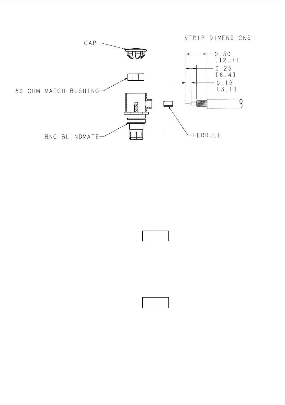
2.3.4 Antenna Cable Connectors
The antenna cable requires a BNC connector at the antenna and a male BNC “Blindmate” connector
(P/N 330-00198-00, supplied with GTX 327 installation kit 010-10216-00) at the transponder. Instructions
for installing the Blindmate BNC are shown in steps A-G. Follow BNC connector manufacturer instructions
for assembly of the BNC connector.
Preliminary
GTX 327 Installation Manual Page 7
190-00187-02 Rev 1
A. Trim coax outer insulation back 0.50”.
B. Trim braid (not center conductor or insulation) back 0.25”.
C. Strip Insulation back 0.120”.
NOTE
Place the ferrule over the coax braid, flush against the coax outer insulation before performing
the next step if the outside diameter of the coax braid is smaller than the inside diameter of the
center connector sidewall opening.
D. Insert cable (center conductor, dielectric and shield braid) through the sidewall of the connector
and solder the center conductor to the center pin of the connector.
NOTE
When using low loss cable it may be necessary to flatten the solid wire center conductor slightly
so it can fit the slot on the RF connector center pin. When soldering, avoid applying excess heat
to the connector body, and center conductor insulator.
E. Heat the outside of the connector sleeve and at the same time apply solder between the braid
and the sleeve. Continue to apply heat until the solder flows evenly.
F. Install 50 V Matching Bushing.
G. Insert connector cap and tack solder in two places.

Preliminary
GTX 327 Installation Manual Page 8
190-00187-02 Rev 1
2.4 GTX 327 INSTALLATION
NOTES
Avoid installing the unit near heat sources. If this is not possible, ensure that additional cooling
is provided. Allow adequate space for installation of cables and connectors. The installer will
supply and fabricate all of the cables. All wiring must be in accordance with FAA
AC 43.13-2A.
A. Assemble the connector/rack kit according to figure B-2. Install the rack assembly according
to the dimensions given in figure B-1. Mounting brackets are not supplied due to the wide
range of mounting configurations available. Suitable mounting brackets may be fabricated
from sheet metal or angle stock. To insure a sturdy mount, rear support for the unit should
be provided.
B. Looking at the bottom of the transponder, make sure the front lobe of the hold down device
is in a vertical position. This can be accomplished by using a 3/32” Allen wrench through
the face plate.
C. Slide the unit into the rack until the front lobe of the unit touches the rack. Guide pins on the
back plate will help in the proper alignment of the unit in the rack.
D. Turn the Allen wrench clockwise until unit is secured in the rack. Continue turning until
tight. Do not overtighten the screw.
E. To remove the unit from the rack, turn the 3/32” Allen wrench counterclockwise until it
disengages from the rack.
2.5 COOLING AIR
The GTX 327 meets all TSO requirements without forced air-cooling. However Garmin recommends forced
air-cooling for all products to increase the long-term reliability. The GTX 327 was designed to handle a
constant 450 PRF, with short periods of 1200 PRF. Rate limit is set at 1200PRF. A typical radar site would
interrogate the transponder once every 5 to 10 seconds for approximately 100 msec at a 400 PRF rate. In
very high traffic areas with multiple ground stations and TCAS traffic it is possible to have long term PRF
rates above 450 PRF. The GTX 327 measures the unit temperature and without force air-cooling the reply
rate will be reduced to protect the transmitter from overheating.
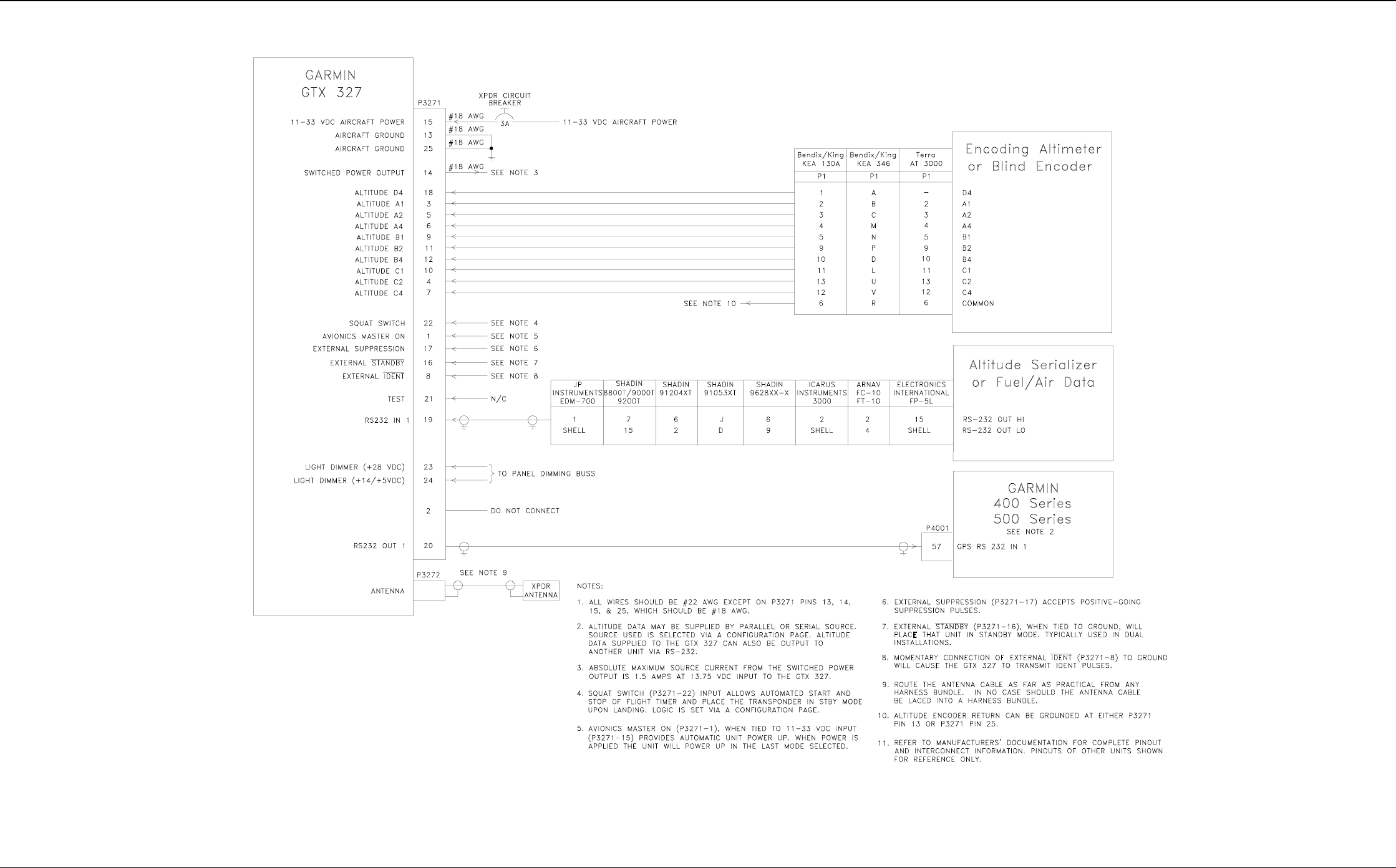
2.6 ELECTRICAL CONNECTIONS
All electrical connections, except for the antenna, are made through a single, 25 pin D connector. Figure 2-1
defines the electrical characteristics of all input and output signals and identifies the cable requirements for
each signal. Required connector and associated hardware are supplied in the installation kit
(P/N 010-10216-00). See figures B-3 and B-4 for interconnect wiring diagrams.

Preliminary
GTX 327 Installation Manual Page 9
190-00187-02 Rev 1
PIN DESCRIPTION I/O
1 AVIONICS MASTER ON In
2 DO NOT CONNECT --
3 ALTITUDE A1 In
4 ALTITUDE C2 In
5 ALTITUDE A2 In
6 ALTITUDE A4 In
7 ALTITUDE C4 In
8 EXTERNAL IDENT INPUT In
9 ALTITUDE B1 In
10 ALTITUDE C1 In
11 ALTITUDE B2 In
12 ALTITUDE B4 In
13 POWER GROUND In
14 SWITCHED POWER OUTPUT Out
15 POWER INPUT (+11 TO +33 VDC) In
16 EXTERNAL STANDBY In
17 EXTERNAL SUPPRESSION In
18 ALTITUDE D4 In
19 RS232 In
20 RS232 Out
21 RESERVED --
22 SQUAT SWITCH In
23 28 VDC PANEL LIGHTING INPUT In
24 14 VDC/5 VDC PANEL LIGHTING INPUT In
25 POWER GROUND In
Figure 2-1. DB-25 Pin-Out Definitions
Preliminary
GTX 327 Installation Manual Page 10
190-00187-02 Rev 1
3. POST INSTALLATION CONFIGURATION & CHECKOUT PROCEDURE
3.1 AIRCRAFT STATION LICENSING REQUIREMENTS
The Telecommunications Act of 1996, effective February 8, 1996, provides the FCC discretion to eliminate
radio station license requirements for aircraft and ships. The GTX 327 installation must comply with current
transmitter licensing requirements. To find out the specific details on whether a particular installation is
exempt from licensing, please see FCC Fact Sheet PR 5000 or contact the FCC at (800)-322-1117.
If an aircraft license is required, make application for a license on FCC form 404, Application for Aircraft
Radio Station License. The FCC also has a fax-on-demand service to provide forms by fax at
(202)-418-0177.
The GTX 327 owner accepts all responsibility for obtaining the proper licensing before using the
transponder.
3.2 OPERATION
NOTE
The coverage you can expect from the GTX 327 is limited to line of sight. Low altitude or
aircraft antenna shielding by the aircraft itself may result in reduced range. Range can be
improved by climbing to a higher altitude. It may be possible to minimize antenna shielding by
locating the antenna where dead spots are only noticed during abnormal flight attitudes.
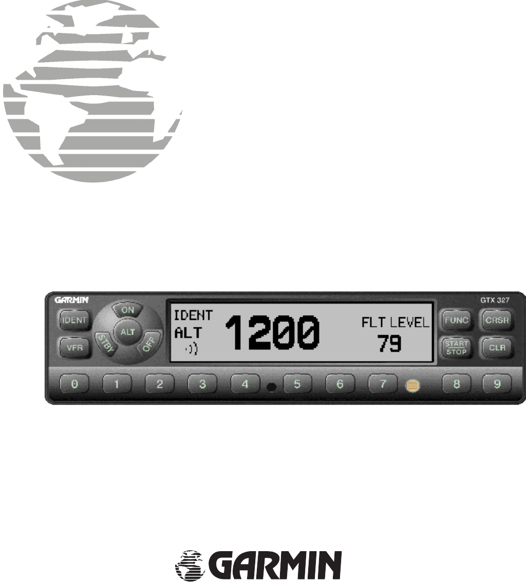
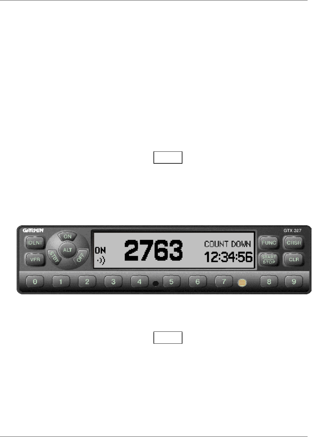
Figure 3-1. GTX 327 Front Panel
NOTE
The GTX 327 should be turned off before starting aircraft engine(s).

Preliminary
GTX 327 Installation Manual Page 11
190-00187-02 Rev 1
3.2.1 Function Selection Switches
The function selection switches are:
• OFF Turns the GTX 327 off.
• STBY Turns the transponder ON in STBY mode or selects STBY mode. When in STBY the
transponder will not reply to any interrogations from the ground radar system. At power
on the last active identification code will be selected.
• ON Turns the transponder ON in Mode A, the identification mode or selects Mode A. At
power on the last active identification code will be selected. In addition to the aircraft’s
identification code, the transponder will also reply to altitude interrogations (mode C) with
signals that do not contain altitude information. The Reply Symbol " ))) " will be
displayed when the transponder replies to ground interrogation.
• ALT Turns the transponder on in Mode A and Mode C, or, if already on, selects Mode A and
Mode C. This is the identification and altitude-reporting modes to respond to ATC aircraft
identification interrogations and altitude interrogations with standard pressure altitude
(29.92 inches Hg.) received from an external altitude digital encoder. The ALT position
may be used in aircraft that are not equipped with the optional altitude encoder, however,
the only response will be discreet signals that do not contain altitude information. The
Reply Symbol " ))) " will be displayed when the transponder replies to ground
interrogation.
NOTE
Any time the ON or ALT function is selected the transponder becomes an active part of the beacon
system. Select ON or ALT as late as practical prior to takeoff and to OFF or STBY as soon as
practical after landing unless previously changed to STBY at the request of ATC. An optional Squat
Switch can automate transponder control during take off and landing. If installed and configured the
Squat Switch will automatically transition the transponder to the ALT mode at take off. Upon
landing the Squat Switch will automatically transition the transponder to STBY mode after a preset
time delay. This time delay can be selected via a configuration page.
• IDENT On occasion, the controller will request to SQUAWK IDENT. Respond by
momentarily pressing and releasing the IDENT button. Pressing the IDENT button
activates the Special Position Identification (SPI) Pulse for 18 seconds identifying your
transponder return from other aircraft on the controller’s scope. The word IDENT will be
displayed in the upper left corner of the display while the IDENT feature is active.
• VFR Programs transponder code to the default VFR code. Default code is programmed on a
configuration page. Pressing the VFR button again will restore the last identification code.

Preliminary
GTX 327 Installation Manual Page 12
190-00187-02 Rev 1
• FUNC Changes modes displayed on the right side of the display. Displayed data includes
Flight Level, Flight Time, Count Up timer, Count Down timer, screen Contrast, and
Display brightness (if configured for manual contrast and brightness.)
Flight Level: Displays the altitude data supplied to the GTX 327 in feet, flight level format or
meters depending on configuration setup.
Flight Time: Displays the flight time controlled by the Start/Stop button if no Squat Switch is
configured or timer starts when the altitude begins to increase. Under Squat Switch
control the timer begins when lift off is sensed.
Count Up Timer: Controlled by START/STOP and CLR button.
Count Down Timer: Controlled by START/STOP, CLR, and CRSR buttons. Count down timer
entered with 0 – 9 buttons.
Contrast: Controlled by 8 and 9 buttons.
Display Brightness: Controlled by 8 and 9 buttons
• START/ STOP Starts and stops the Count Up and Count Down timers.
• CRSR Activates the change fields for the Count Down timer when selected by the FUNC key.
• CLR Resets the Count Up and Count Down timers.
• 8 Reduces screen Contrast and display Brightness. Enters the number eight into the Count
Down timer.
• 9 Increases screen Contrast and display Brightness. Enters the number nine into the Count
Down timer.
3.2.2 Code Selection
The code selector consists of eight push button (0 – 7) switches that provide 4,096 active identification
codes. Pushing one of these buttons begins the code selection sequence. The new code will not be activated
and stored in EEPROM until the forth button is pressed. Pressing the CLR button will cancel the previous
button press and restore the code prior to the last button press. Pressing the CRSR button when data entry
has begun will remove the cursor and cancel data entry. If an identification code entry is not completed or
there is no other key press for four seconds the last active code will be restored.
NOTE
Attention should be paid to the selected identification code. The selected code should be the one
assigned by air traffic control for IFR flight or rules applicable to transponder use for VFR flight.
Care should be taken not to select code 7500 and all codes in the 7600 and 7700 series (i.e., 7600-7677,
7700-7777) which trigger special indicators in automated facilities. Only nondiscrete code 7500 will be
decoded as the hijack code. An aircraft’s transponder code (when available) is utilized to enhance the
tracking capabilities of the ATC facility, therefore care should be taken when making routine code changes.

Preliminary
GTX 327 Installation Manual Page 13
190-00187-02 Rev 1
3.2.3 Configuration Pages
Holding down the CRSR button and pressing the ON button provides access to the configuration pages. The
FUNC button will sequence through the configuration pages. The CRSR button will highlight selectable
fields on each page. When a field is highlighted, numeric data entry will be performed with the 0-9 buttons,
and list selections will be performed with the 8 or 9 buttons. Changes made through the configuration pages
are stored in EEPROM memory.
• Display Backlight Page
Current display backlight intensity: displayed value
Select manual or automatic backlight source
Automatic backlight source: Select automatic backlight source (Photocell, 28Vdc, 5Vdc)
Display backlight filter response time: Select display backlight response time (3-7) (default to 4)
Display backlight filter slope: Select display backlight filter slope value (0-99) (default to 50)
Display backlight filter minimum value: Select display minimum filter slope value (0-99) (default to 50)
Display backlight filter offset: Select display backlight filter offset value (0-99) (default to 50)
• Key Backlight Page
Current key backlight intensity: Displayed value
Automatic key backlight source: Select automatic key backlight source (Photocell, 28Vdc, 5Vdc)
Key backlight filter response time: Select key backlight response time (3-7) (default to 4)
Key backlight filter slope: Select key backlight filter slope value (0-99) (default to 50)
Key backlight filter minimum value: Select key minimum filter slope value (0-99) (default to 50)
Key backlight filter offset: Select key backlight filter offset value (0-99) (default to 50)
• Contrast Configuration Page
Select contrast mode (Auto, Manual) (default, to Auto)
Select contrast offset (0 to99) (default, to 50)
• Operation Configuration Page #1
VFR identification code: Enter the VFR identification code (default 1200)
Altitude Input source: Select the altitude input source [Gray code(default), Icarus, Shadin]
Altitude display format: Select altitude display format [Flight level (default), Feet, Meters]
Aircraft climb rate: Enter aircraft climb rate [100 to 2000 fpm (500 fpm default)]
• Operation Configuration Page #2
SQUAT SWITCH sense
Automatic STBY operation enabled
Automatic STBY delay duration
• Gray Code Input Configuration Page
Gray Code discretes
Gray Code altitude
• Discrete Input Configuration Page
EXTERNAL IDENT input:
EXTERNAL STANDBY input:
SQUAT SWITCH input: On ground equals High or Low

Preliminary
GTX 327 Installation Manual Page 14
190-00187-02 Rev 1
APPENDIX A CERTIFICATION DOCUMENTS
A.1 CONTINUED AIRWORTHINESS
Other than for regulatory periodic functional checks, maintenance of the GTX 327 is “on condition” only.
Refer to the GTX 327 Maintenance Manual, (Garmin P/N 190-00187-05). Periodic maintenance of the
GTX 327 is not required.

Preliminary
GTX 327 Installation Manual Page 15
190-00187-02 Rev 1
A.2 ENVIRONMENTAL QUALIFICATION FORM
NOMENCLATURE: GTX 327 Airborne ATC Transponder Equipment
TYPE/MODEL/PART NO.: 010-00188-( )
TSO/JTSO COMPLIANCE: TSO - C74c Class 1A
JTSO
MANUFACTURER’S SPECIFICATION AND/OR OTHER
APPLICABLE SPECIFICATION: 004-00070-00 minimum Performance Specification
MANUFACTURER: GARMIN INTERNATIONAL
ADDRESS: 1200 E 151st St, Olathe, Kansas 66062
Conditions Section Description of Conducted Tests
Temperature and Altitude 4.0 Equipment tested to Categories A1 & D1 except as noted
Low Temperature 4.5.1 -208 C
High Temperature 4.5.2. & 4.5.3 +558 C
In-Flight Loss of Cooling 4.5.4 Cooling air not required
Altitude 4.6.1 50,000 Feet
Decompression 4.6.2 8,000 to 50,000 Feet
Overpressure 4.6.3 -15,000 Feet
Temperature Variation 5.0 Equipment tested to Category C
Humidity 6.0 Equipment tested to Category A
Shock 7.0 Equipment tested according to DO-160C, Par. 7.2.1
Operational 7.2 6 g’s
Crash Safety 7.3 15 g’s
Vibration 8.0 Equipment tested without shock mounts to Categories B,
M and N (Table 8-1)
Explosion 9.0 Equipment identified as Category X, no test required
Waterproofness 10.0 Equipment identified as Category X, no test required
Fluids Susceptibility 11.0 Equipment identified as Category X, no test required

Preliminary
GTX 327 Installation Manual Page 16
190-00187-02 Rev 1
Conditions Section Description of Conducted Tests
Sand and Dust 12.0 Equipment identified as Category X, no test required
Fungus 13.0 Equipment identified as Category X, no test required
Salt Spray 14.0 Equipment identified as Category X, no test required
Magnetic Effect 15.0 Equipment tested to Class Z
Power Input 16.0 Equipment tested to Category B
Voltage Spike 17.0 Equipment tested to Category A
Audio Frequency
Susceptibility 18.0 Equipment tested to Category B
Induced Signal Susceptibility 19.0 Equipment tested to Category A
Radio Frequency
Susceptibility 20.0 Equipment tested to Category T
Radio Frequency Emission 21.0 Equipment tested to Category Z
Lightning Induce Transient
Susceptibility 22.0 Equipment identified as Category XXXX, no test
required
Lightning Direct Effects 23.0 Equipment identified as Category X, no test required
Icing 24.0 Equipment identified as Category X, no test required

Preliminary
GTX 327 Installation Manual Page 17
190-00187-02 Rev 1
APPENDIX B
ASSEMBLY AND INSTALLATION DRAWINGS
Preliminary
GTX 327 Installation Manual Page 18
190-00187-02 Rev 1
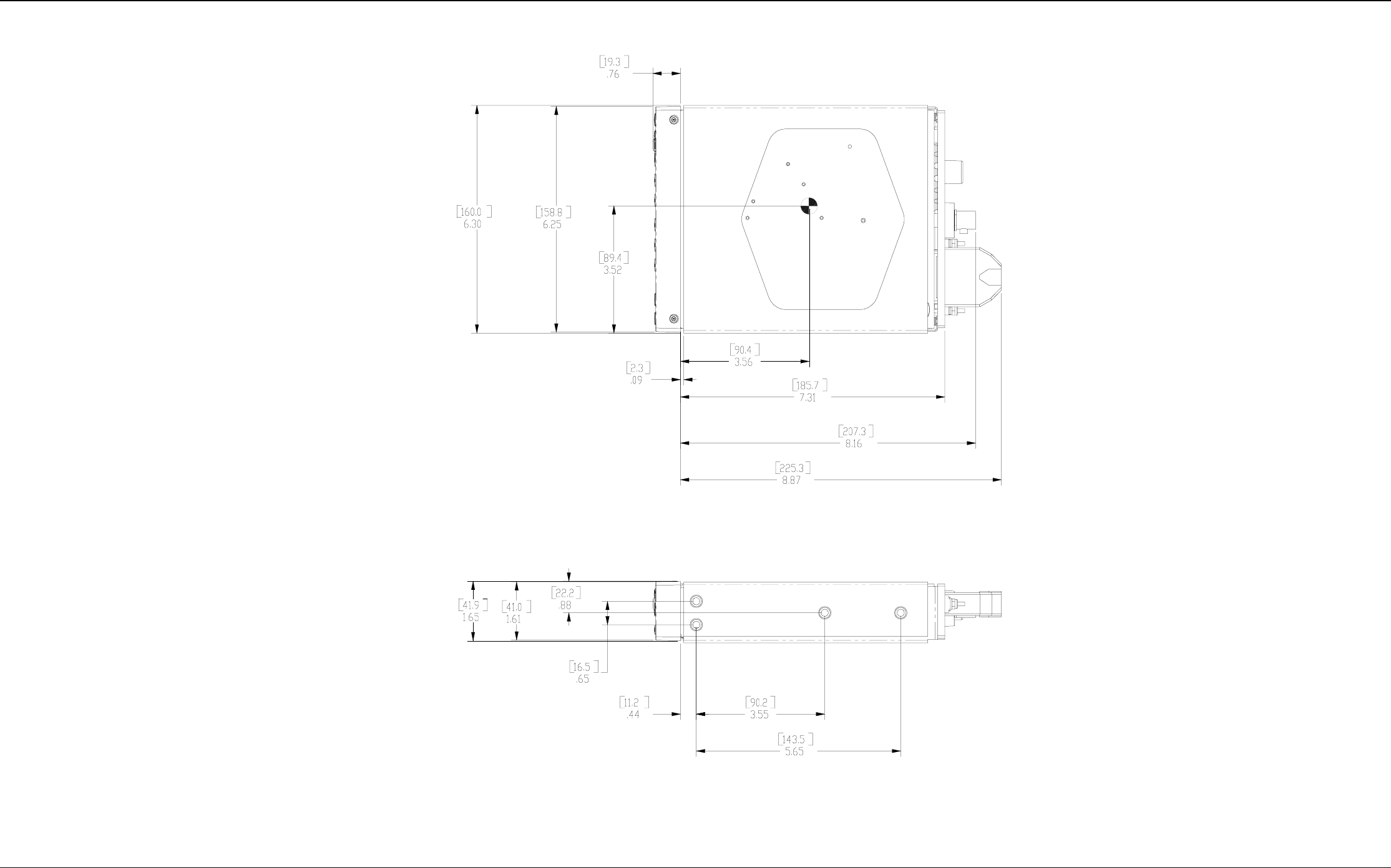
Figure B1 GTX 327 OUTLINE DRAWING
Preliminary
GTX 327 Installation Manual Page 19
190-00187-02 Rev 1
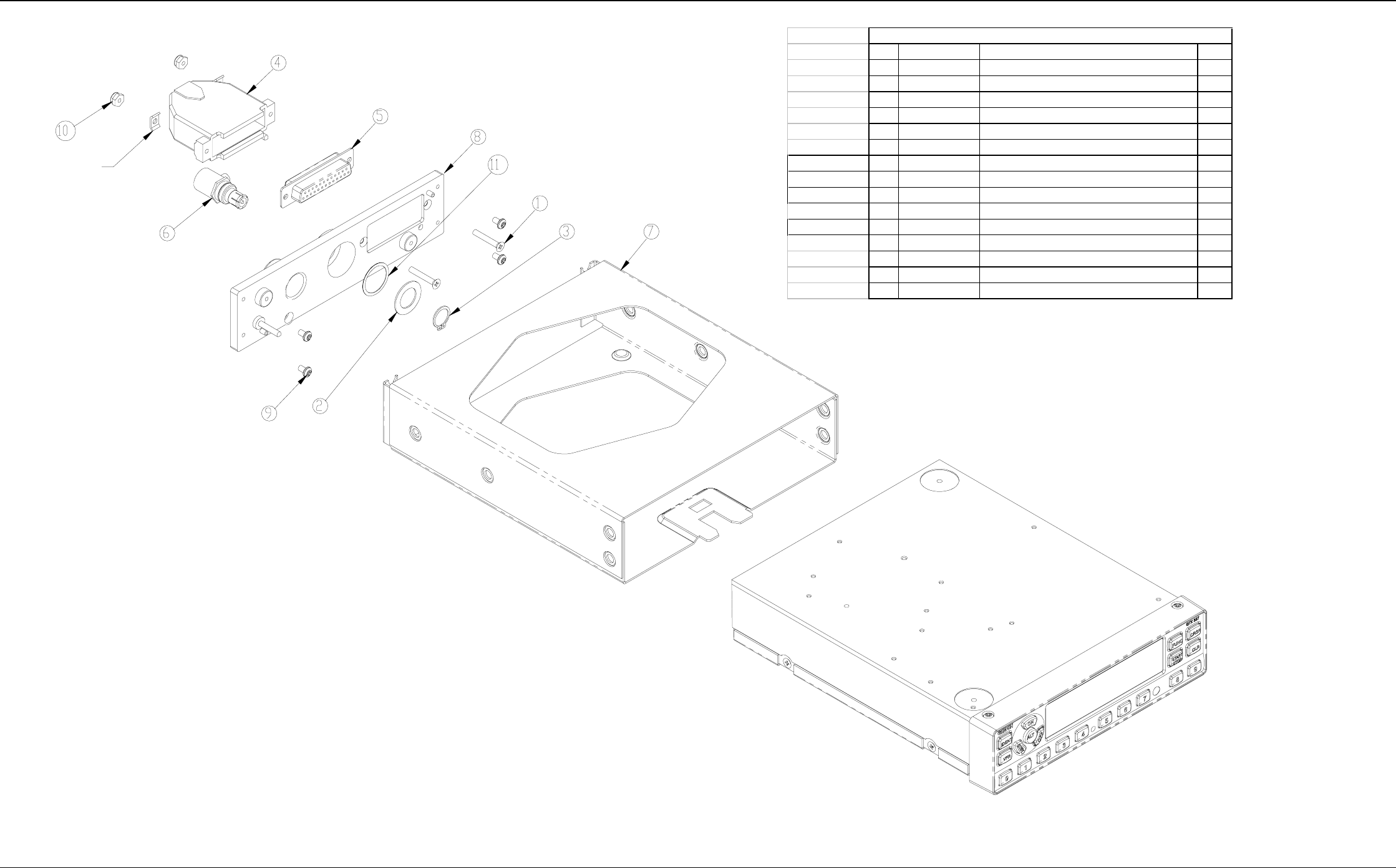
Item Part Number Description Qty
1 211-62204-16 SCREW, 4-40 X .75, FLHP, SS/P 2
2 212-2S001-00 WSHR, FLAT, NON-STD, SS 1
3 232-00013-01 SNAP RING, EXT, 7/16 1
4 330-00113-25 BACKSHELL, MTLZ PLSTC, 25 CONT. 1
5 330-00184-25 CONN., D-SUB, MIL CRP, SCKT, 25 1
6 330-00198-00 CONN. BNC, MALE BLINDMATE 1
NOT SHOWN 336-00022-00 CONT. SCKT, MIL CRP, SIZE 20 25
NOT SHOWN 336-00023-00 CONT. SCKT, MIL CRP, SIZE 20-18 5
NOT SHOWN 312-00005-05 TUBING, HT SHRINK 2.3IN
7 115-00285-00 INSTALL RACK 1
NOT SHOWN 161-00215-00 LABEL, S/N, INSTL RACK 1
8 125-00032-02 BACK PLATE 1
9 211-60234-06 SCREW, 4-40X.187, PHP, SS/P 4
10 210-10000-04 NUT, HEX NY LCKNG, 4-40 2
11 234-10002-00 SPRING WASHER 1
011-00338-00 CONNECTOR/RACK KIT
NOTES:
1. THIS PART IS SUPPLIED WITH ITEM 4.
NOTE 1
Figure B2 GTX 327 CONNECTOR/RACK KIT ASSEMBLY DRAWING
Preliminary
GTX 327 Installation Manual Page 20
190-00187-02 Rev 1
Figure B3 GTX 327 INTERCONNECT WIRING DIAGRAM
Preliminary
GTX 327 Installation Manual Page 21
190-00187-02 Rev 1
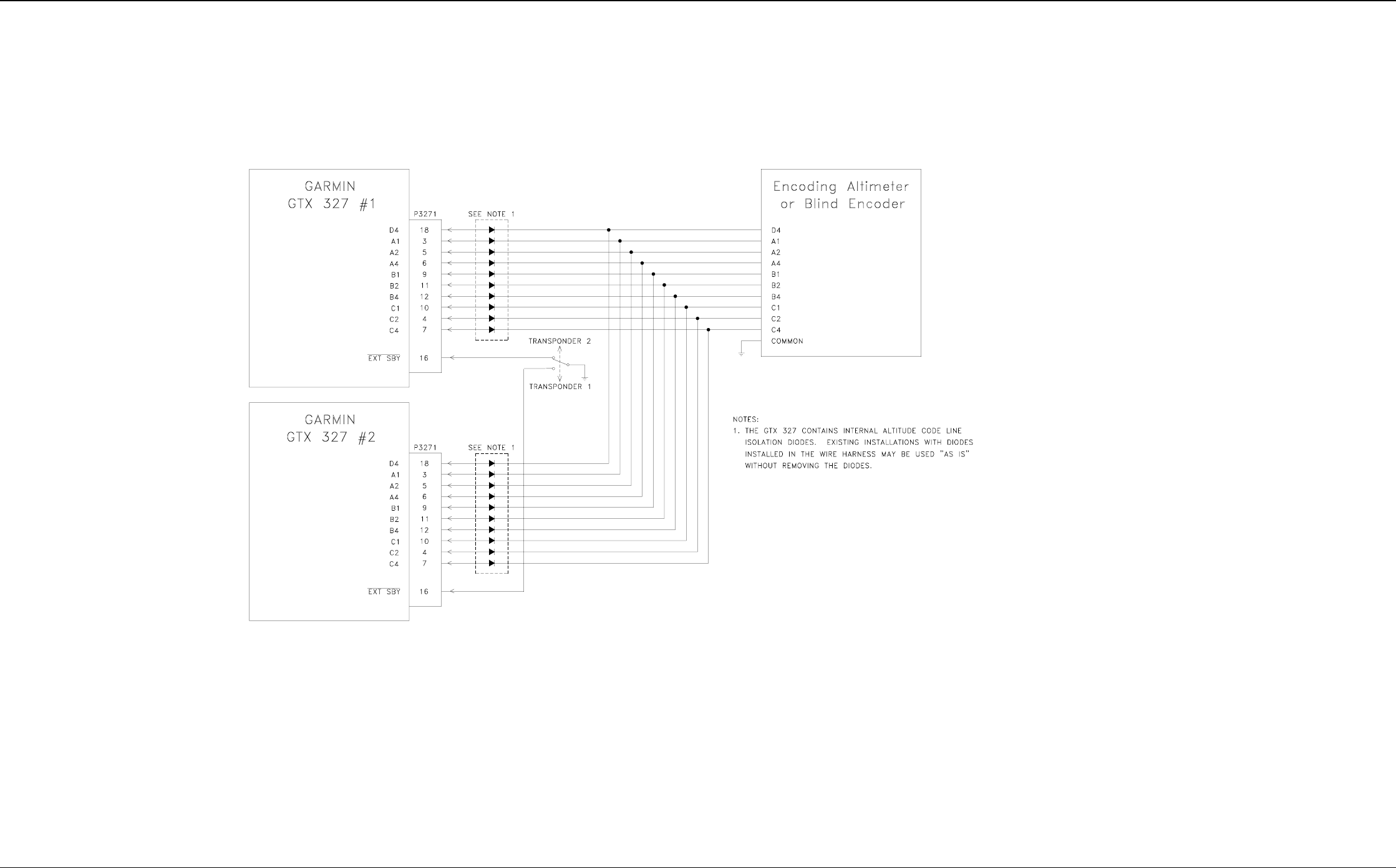
Figure B4 DUAL TXP INTERCONNECT WIRING DIAGRAM, ENCODING ALTITUDE CONNECTIONS

Preliminary
GTX 327 Installation Manual Page 22
190-00187-02 Rev 1
APPENDIX C
STC PERMISSION
Consistent with N8110.69 or Order 8110.4, Aviation Authority approved installations are hereby granted
permission to use ST2484WI-A data to modify aircraft.