Garmin 0046400 Aviation Transponder User Manual 330Cover
Garmin International Inc Aviation Transponder 330Cover
UserManual.wiki
>
Garmin
>
0046400 User Manual
users manual
Navigation menu
Upload a User Manual
Namespaces
Wiki Guide
HTML
PDF
Info
Views
User Manual
Discussion / Help
Navigation


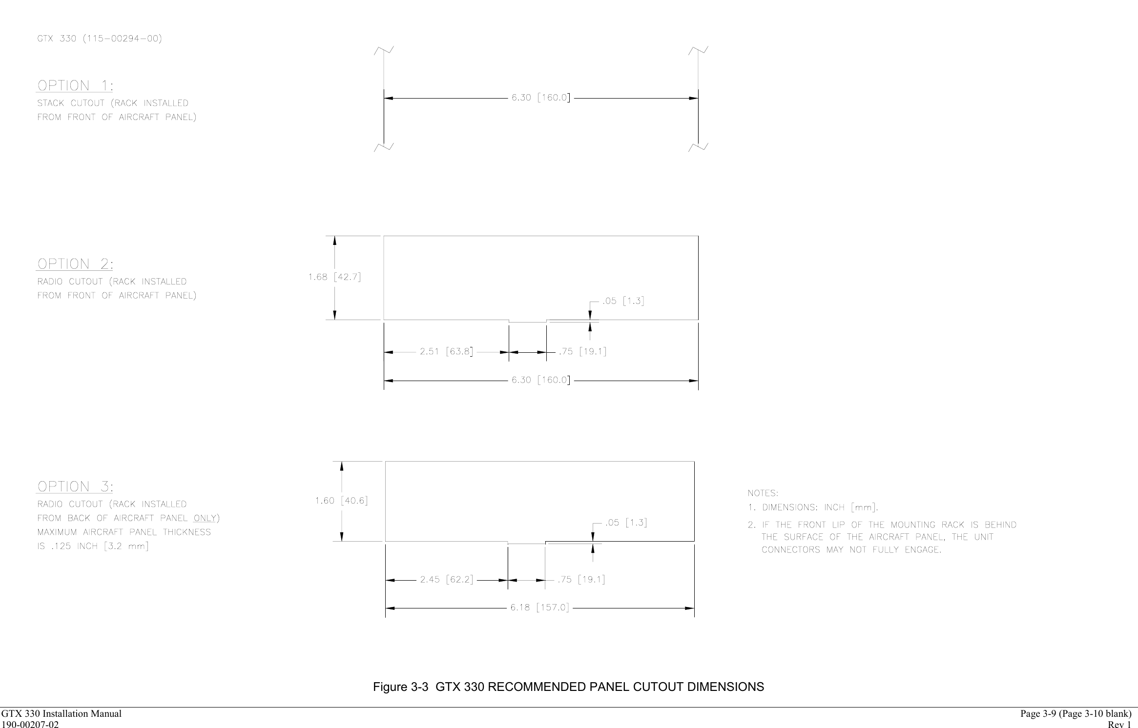

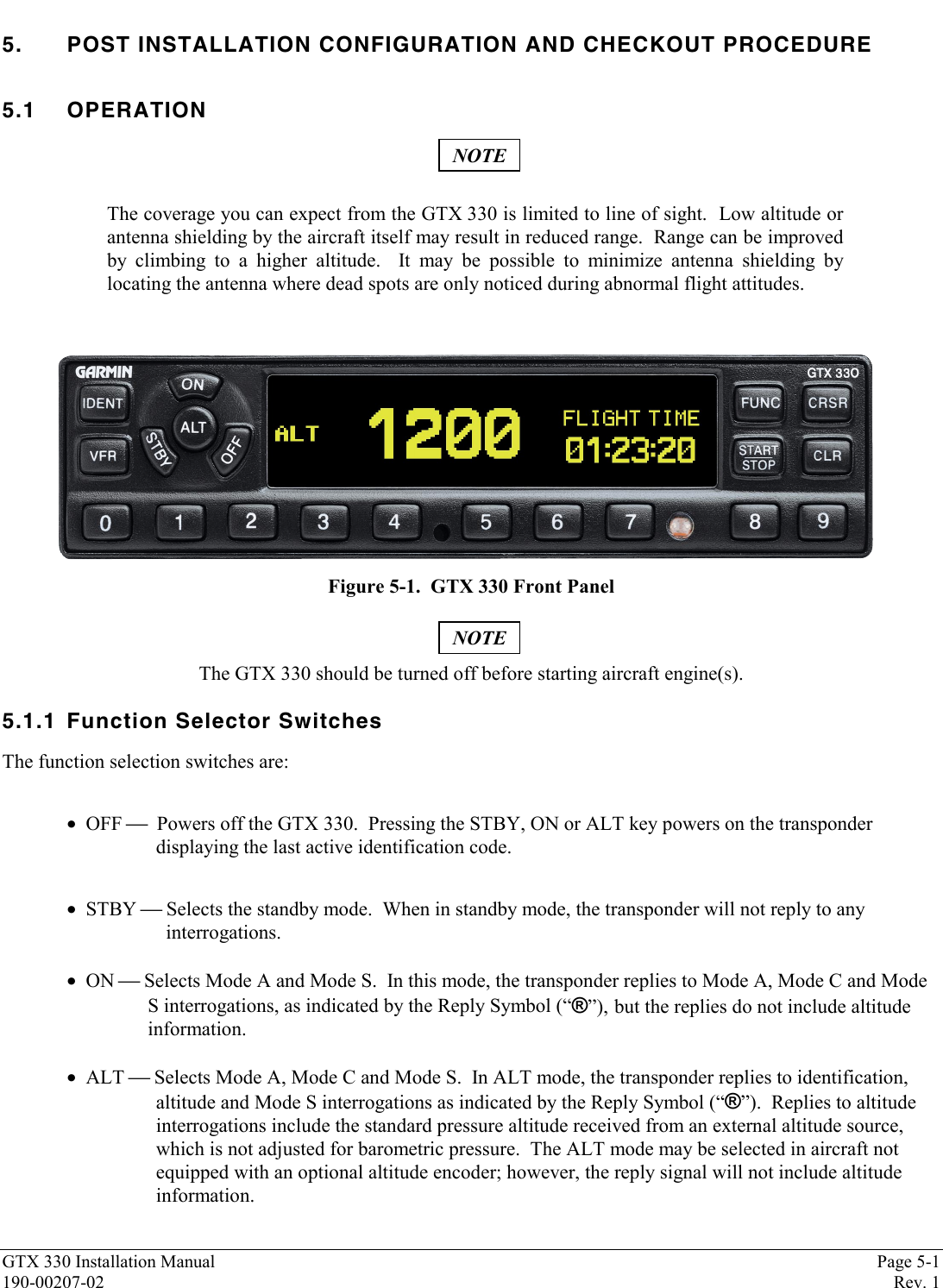
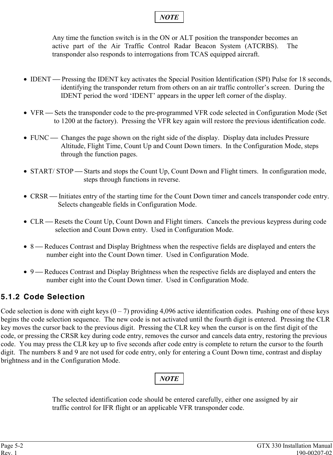
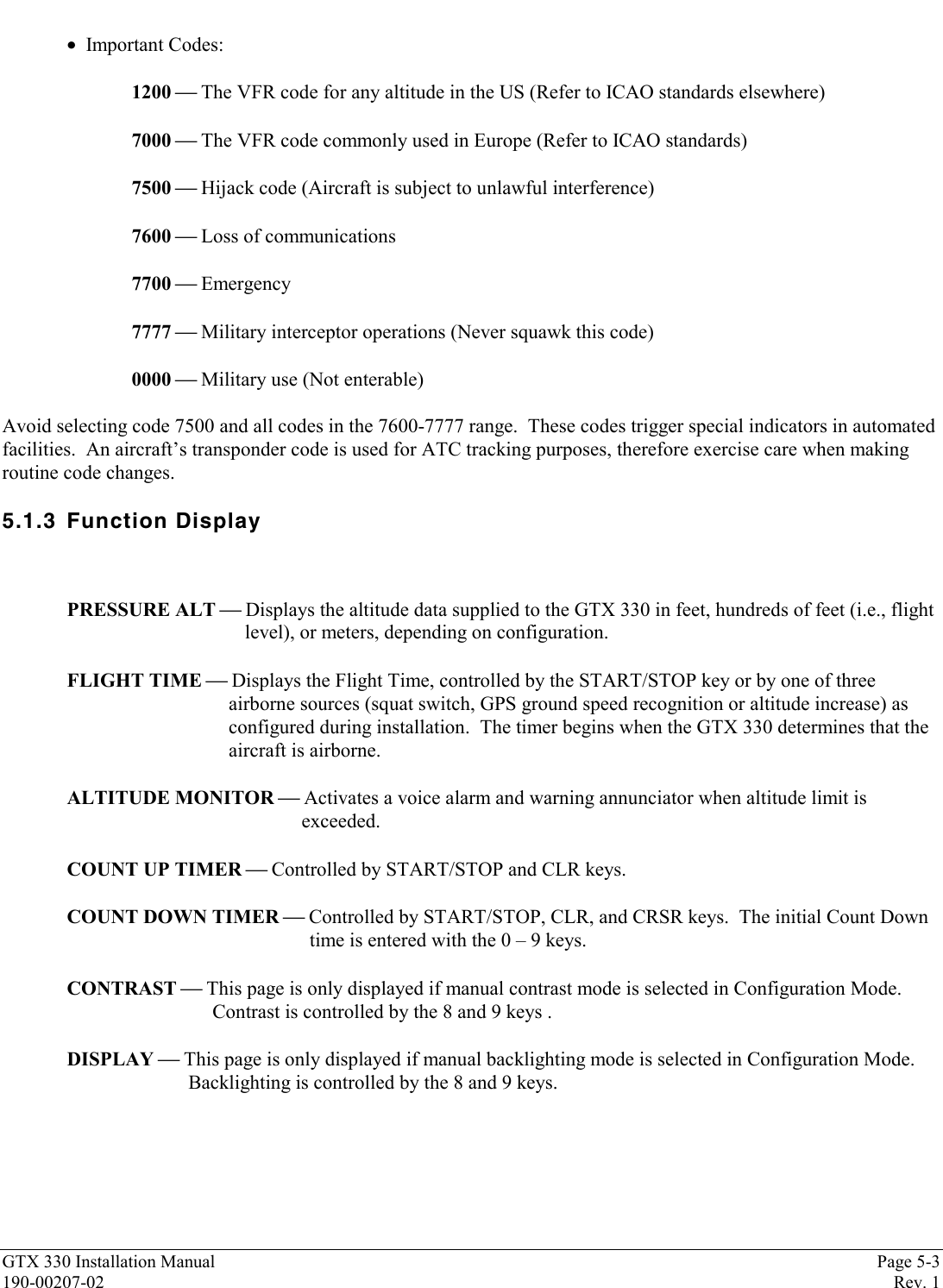
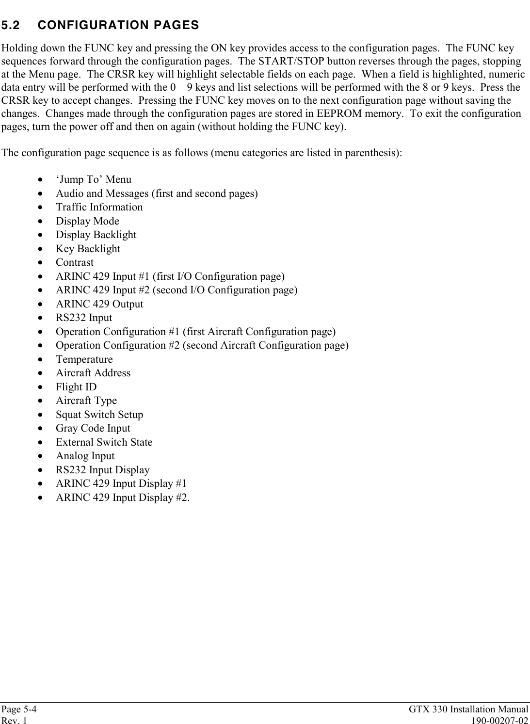

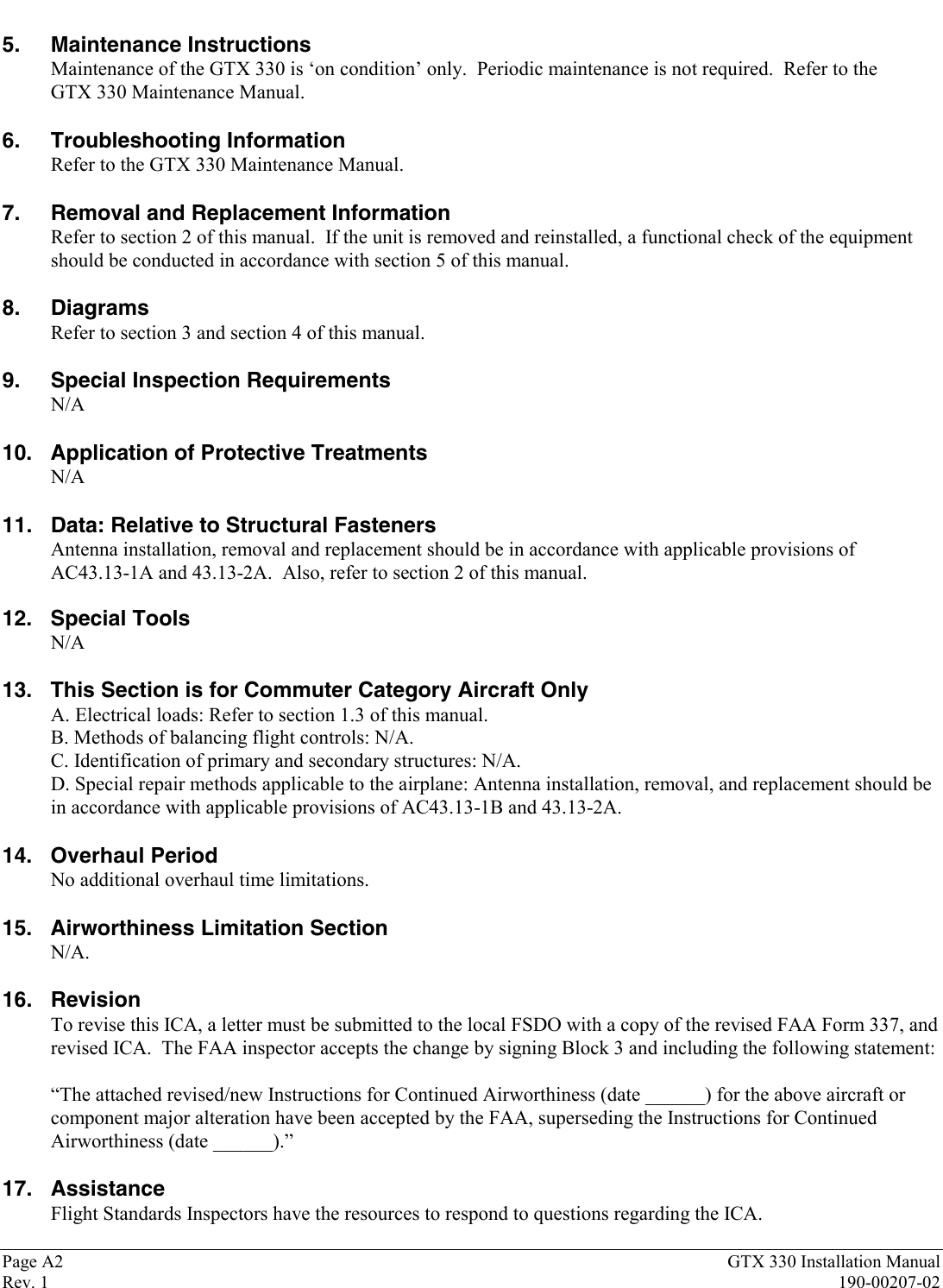
![GTX 330 Installation Manual Page A1190-00207-02 Rev. 1APPENDIX A CERTIFICATION DOCUMENTSA.1 Continued AirworthinessOther than for regulatory periodic functional checks, maintenance of the GTX 330 is “on condition” only. Refer tothe GTX 330 Maintenance Manual, (Garmin P/N 190-00207-05). Periodic maintenance of the GTX 330 is notrequired.This section provides assistance to the installing agency in preparing Instructions for Continued Airworthiness (ICA)in response to Bulletin Number HBAW 98-18, “Checklist for Instructions for Continued Airworthiness for MajorAlterations Approved Under the Field Approval Process”, effective 10/7/98.Aviation Authority approved installers are hereby granted permission to reference appropriate service instructionsand excerpts from this Installation Manual to accomplish the Instructions for Continued Airworthiness. Thispermission does not construe suitability of the documents. It is the applicant’s responsibility to determine thesuitability of the documents for the ICA.Following is a suggested ICA for a GARMIN GTX 330 unit installation. Some of the checklist items do not apply, inwhich case they should be marked “N/A” (Not Applicable).INSTRUCTIONS FOR CONTINUED AIRWORTHINESS, GARMIN GTX 3301. Introduction[Aircraft that has been altered: Registration (N-) number, Make, Model and Serial Number]Content, Scope,Purpose and Arrangement: This document identifies the Instructions for Continued Airworthiness forthe modification of the above aircraft by installation of a GARMIN GTX 330.Applicability: Applies to aircraft altered by installation of the GARMIN GTX 330.Definitions and Abbreviations: None, N/A.Precautions: None, N/A.Units of Measurement: None, N/A.Referenced Publications: GARMIN GTX 330 Installation Manual, P/N 190-00207-02GARMIN GTX 330 Maintenance Manual, P/N 190-00207-05GARMIN STC # [applicable STC number for the specific model installed, refer to Appendix B of this manual].GARMIN GTX 330 Pilot’s Guide, P/N 190-00207-xx.Distribution: This document should be a permanent aircraft record.2. Description of the AlterationInstallation of the GARMIN GTX 330, with interface to Encoding Altimeter or Blind Encoder. Refer tosection 4 and figures 4-1 and 4-2 of this manual for interconnect information. Antenna installation, removaland replacement should be in accordance with applicable provisions of AC43.13-1B and 43.13-2A.3. Control, Operation InformationRefer to the GTX 330 Pilot’s Guide.4. Servicing InformationN/A](https://usermanual.wiki/Garmin/0046400/User-Guide-252626-Page-42.png)