Garmin 0046400 Aviation Transponder User Manual 330Cover
Garmin International Inc Aviation Transponder 330Cover
Garmin >
users manual
â
ââ
â
GARMIN International, Inc.
1200 E. 151st Street
Olathe, KS 66062 USA
190-00207-02 Revision 1
March 2002
GTXTM 330, GTXTM 330D
TRANSPONDER
INSTALLATION
MANUAL

Page A GTX 330 Installation Manual
Rev. 1 190-00207-02
© Copyright 2002
GARMIN Ltd. or its subsidiaries
All Rights Reserved
Except as expressly provided herein, no part of this manual may be reproduced, copied, transmitted,
disseminated, downloaded or stored in any storage medium, for any purpose without the express prior
written consent of GARMIN. GARMIN hereby grants permission to download a single copy of this manual
and of any revision to this manual onto a hard drive or other electronic storage medium to be viewed and to
print one copy of this manual or of any revision hereto, provided that such electronic or printed copy of this
manual or revision must contain the complete text of this copyright notice and provided further that any
unauthorized commercial distribution of this manual or any revision hereto is strictly prohibited.
Information in this document is subject to change without notice. GARMIN reserves the right to change or
improve its products and to make changes in the content without obligation to notify any person or
organization of such changes or improvements.
GARMIN International, Inc.
1200 E. 151st Street
Olathe, KS 66062 USA
Telephone: 913-397-8200
Dealer Line: 1-800-800-1420
Web Site Address: www.garmin.com
INFORMATION SUBJECT TO EXPORT CONTROL LAWS
This document may contain information which is subject to the Export Administration Regulations (“EAR”)
issued by the United States Department of Commerce (15 CFR, Chapter VII, Subchapter C) and which may
not be exported, released, or disclosed to foreign nationals inside or outside of the United States without
first obtaining an export license. A violation of the EAR may be subject to a penalty of up to 10 years
imprisonment and a fine of up to US$1,000,000 under Section 2410 of the Export Administration Act of
1979. Include this notice with any reproduced portion of this document.
RECORD OF REVISIONS
Revision Revision
Date
Description ECO #
103/22/00 Preliminary Release -

GTX 330 Installation Manual Page i
190-00207-02 Rev 1
TABLE OF CONTENTS
To be supplied

Page ii GTX 330 Installation Manual
Rev 1 190-00207-02
This page intentionally left blank

GTX 330 Installation Manual Page 1-1
190-00207-02 Rev. 1
1. GENERAL DESCRIPTION
1.1 INTRODUCTION
This manual describes the physical, mechanical, and electrical characteristics and the installation requirements for the
GTX 330 Mode S Transponder and GTX 330D Diversity Mode S Transponder. In this manual, the term GTX 330
applies to both transponders unless otherwise stated. Information pertaining to the maintenance, alignment, and
procurement of replacement parts is found in the GTX 330 Maintenance Manual, P/N 190-00207-05. After
installation of the GTX 330, FAA Form 337 must be completed by an appropriately certificated agency to return the
aircraft to service.
1.2 EQUIPMENT DESCRIPTION
The Garmin GTX 330 is a panel mounted Mode S Transponder with the addition of timers, altitude reporting, mode S
interrogation and reply, and multiple transmit/receive ARINC 429 and RS232 data ports. The Mode S transponder
has the capability to transmit a unique address for every aircraft.
The GTX 330 is a radio transmitter and receiver that operates on radar frequencies, receiving ground radar or TCAS
interrogations at 1030 MHz and transmitting a coded response of pulses to ground-based radar on a frequency of
1090 MHz. The GTX 330 is equipped with IDENT capability that activates the Special Position Identification (SPI)
pulse for 18 seconds.
As with other Mode A/Mode C transponders, the GTX 330 replies with any one of 4,096 codes, which differ in the
position and number of pulses transmitted. By replying to ground transmissions or TCAS interrogations, the
GTX 330 enables ATC to display aircraft identification, altitude and ground speed as well as identification numbers
on ATC radar screens or TCAS traffic indicators.
The GTX 330 is configured with all key controls. The layout of the front panel keys and displays segregates the
transponder’s primary functions from the secondary functions. The unit can be configured so the aircraft avionics
master bus can turn the unit on.
1.3 INTERFACE SUMMARY
The GTX 330 provides the following interface connections via the rear connector:
• Ten (10) encoding altimeter inputs.
• External IDENT input.
• External STBY input.
• External suppression pulse input.
• Switched power output of up to 1.5 amps (for digital altitude encoder power).
• Aircraft power input (11 to 33 volts).
• Aircraft dimming buss input voltage.
• Aircraft master switch turn-on option.

Page 1-2 GTX 330 Installation Manual
Rev. 1 190-00207-02
• Serial altitude or GPS groundspeed input.
• Serial altitude output.
• Mode S with Extended Squitter, Comm A and Comm B protocol.
• Temperature, Altitude Hold, Density Altitude and the ability to enter flight ID or tail numbers.
• Digitally recorded voice and discrete warning annunciator activated by Altitude Hold when limits are exceeded.
• Diversity: GTX 330 is available with or without the Diversity feature.
1.4 GTX 330 TECHNICAL SPECIFICATIONS
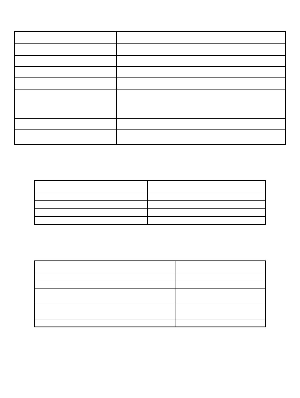
1.4.1 GTX 330 Electrical Specifications
SPECIFICATION CHARACTERISTIC
TSO, JTSO; GTX 330 TSO-C112 CL2A4 121 010, JTSO-2C112a.
TSO, JTSO; GTX 330D TSO-C112 CL2A4 121 011, JTSO-2C112a.
TSO ENV CAT Refer to appendix A
Applicable Documents RTCA DO-160D, DO-181C
Temperature Range -45°C to +55°C (Continuous Operation)
Power Requirements 11.0 to 33.0 Vdc; Power Input: 22 Watts typical,
45 Watts Maximum
Humidity 95% @ +55°C for 16 Hours; 85% @ +38°C for 32
Hours
Altitude 55,000 Feet
Transmitter Frequency 1090 MHz
Transmitter Power 125 Watts minimum, 250 Watts nominal.
Receiver Frequency 1030 MHz
Receiver Sensitivity -74 dBm Nominal for 90% replies
Mode A Capability 4096 Identification Codes
Mode C Capability 100 Foot Increments from -1000 to 62,700 feet.
25 Foot Increments with suitable serial data link.
Mode S Capability Aircraft Identification, Altitude and Ground Speed
External Suppression Input Low ≤ 0.5 V; High ≥ 8 V
GTX 330 Installation Manual Page 1-3
190-00207-02 Rev. 1
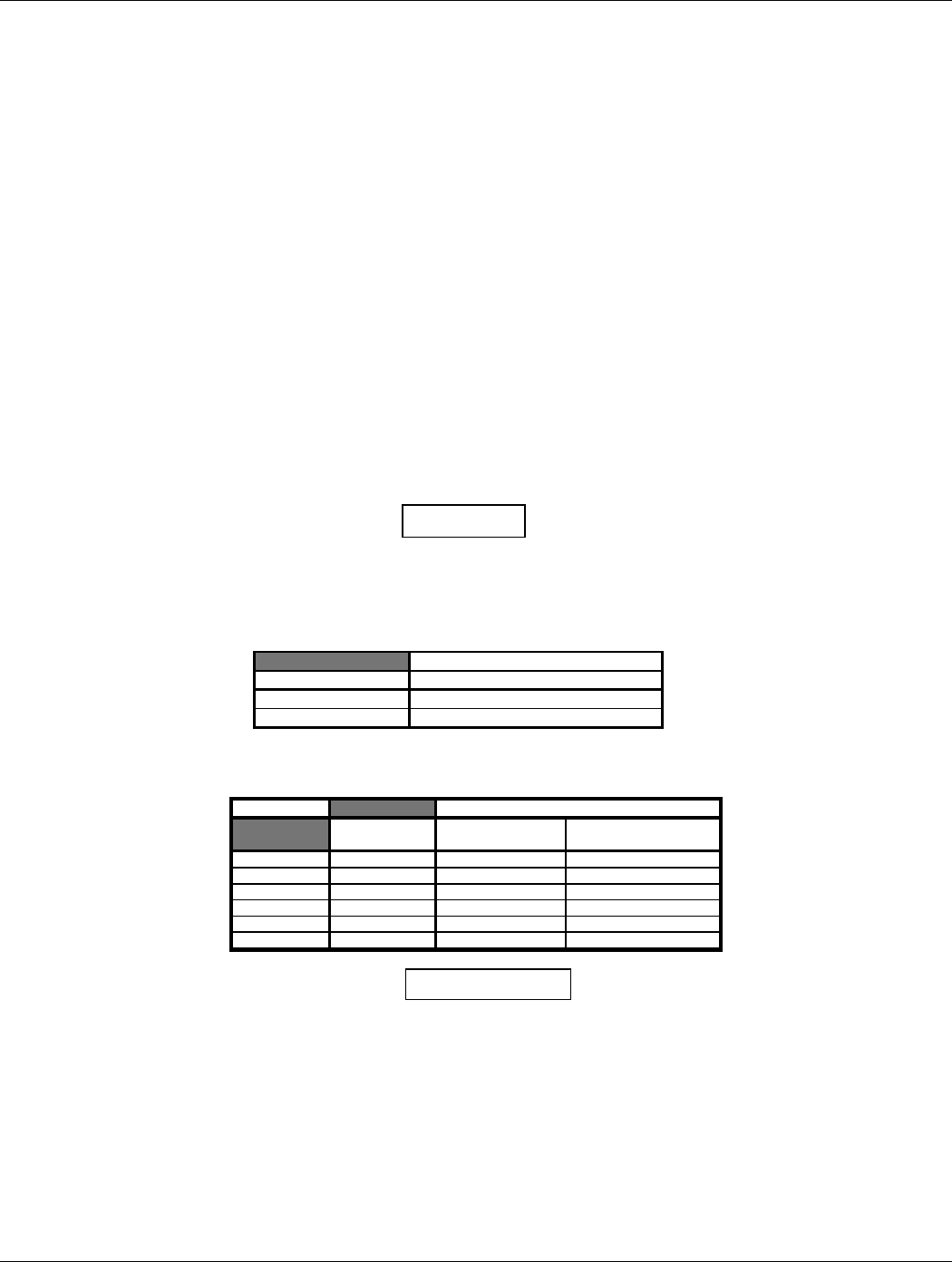
1.4.2 Physical Characteristics of the GTX 330
SPECIFICATION CHARACTERISTIC
Bezel Height 1.65 inches (42 mm)
Bezel Width 6.25 inches (159 mm)
Rack Height (Dimple to Dimple) 1.68 inches (43 mm)
Rack Width 6.30 inches (160 mm)
Depth Behind Panel with
Connectors (measured from face
of aircraft panel to rear of
connector backshells)
11.25 inches (286 mm)
GTX 330 Unit Weight 3.4 lbs. (1.5 kg)
GTX 330 Rack Weight (Installed
with rack and connectors)
4.2 lbs. (1.9 kg)
1.4.3 GTX 330 Configurations Available
GARMIN P/N GTX 330 Description
010-00230-00 Black Front Panel
010-00230-20 Gray Front Panel
010-00230-10 Black Front Panel, Diversity
010-00230-30 Gray Front Panel, Diversity
1.4.4 Equipment Available
ITEM GARMIN P/N
Sub Assy, Connector Kit, GTX 330 011-00583-00
SMP, Install Rack, GTX 330 115-00294-00
Sub Assy, Backplate, GTX 330 011-00582-00
(For use with GTX 330)
Sub Assy, Backplate, GTX 330D 011-00582-01
(For use with GTX 330D)
GARMIN GTX 330 Antenna kit 010-10160-00

Page 1-4 GTX 330 Installation Manual
Rev. 1 190-00207-02
1.4.5 Additional Equipment Required
•Antenna Sealant - Use antenna manufacturer’s instructions, install according to FAA AC 43.13-2A.
•Cables - The installer will supply all system cables including circuit breakers. Cable requirements and
fabrication is detailed in Section 2 of this manual.
•Hardware - #6 Flat Head Screw (6 ea.) and #6-32 Self-Locking Nut (6 ea.). Hardware required to
mount installation rack is not provided.
•Encoding Altitude Digitizer - Use encoding altimeter manufacturer’s instructions, install according to
FAA AC 43.13-2A.
1.5 INSTALLATION APPROVAL
The conditions and tests required for TSO approval of the GTX 330 Transponder and antenna are minimum
performance standards. It is the responsibility of those desiring to install this transponder and antenna either on or
within a specific type or class of aircraft to determine that the aircraft installation standards are within the TSO
standards. For GTX 330 TSO compliance, see Appendix A. For antenna TSO compliance, refer to antenna
manufacturer’s literature.
1.6 AIRCRAFT STATION LICENSING REQUIREMENTS
The Telecommunications Act of 1996, effective February 8, 1996, provides the FCC discretion to eliminate radio
station license requirements for aircraft and ships. The GTX 330 installation must comply with current transmitter
licensing requirements. To find out the specific details on whether a particular installation is exempt from licensing,
please see FCC Fact Sheet PR 5000 or contact the FCC at (800)-322-1117.
If an aircraft license is required, make application for a license on FCC form 404, Application for Aircraft Radio
Station License. The FCC also has a fax-on-demand service to provide forms by fax at (202)-418-0177.
The GTX 330 owner accepts all responsibility for obtaining the proper licensing before using the transponder.

GTX 330 Installation Manual Page 1-5
190-00207-02 Rev. 1
1.7 LIMITED WARRANTY
GARMIN warrants this product to be free from defects in materials and manufacture for one year from the date of
purchase. GARMIN will, at its sole option, repair or replace any components that fail in normal use. Such repairs or
replacement will be made at no charge to the customer for parts or labor. The customer is, however, responsible for
any transportation costs. This warranty does not cover failures due to abuse, misuse, accident or unauthorized
alteration or repairs.
THE WARRANTIES AND REMEDIES CONTAINED HEREIN ARE EXCLUSIVE AND IN LIEU OF ALL
OTHER WARRANTIES EXPRESS OR IMPLIED OR STATUTORY, INCLUDING ANY LIABILITY ARISING
UNDER ANY WARRANTY OF MERCHANTABILITY OR FITNESS FOR A PARTICULAR PURPOSE,
STATUTORY OR OTHERWISE. THIS WARRANTY GIVES YOU SPECIFIC LEGAL RIGHTS, WHICH MAY
VARY FROM STATE TO STATE.
IN NO EVENT SHALL GARMIN BE LIABLE FOR ANY INCIDENTAL, SPECIAL, INDIRECT OR
CONSEQUENTIAL DAMAGES, WHETHER RESULTING FROM THE USE, MISUSE, OR INABILITY TO USE
THIS PRODUCT OR FROM DEFECTS IN THE PRODUCT. SOME STATES DO NOT ALLOW THE
EXCLUSION OF INCIDENTAL OR CONSEQUENTIAL DAMAGES, SO THE ABOVE LIMITATIONS MAY
NOT APPLY TO YOU.
To obtain warranty service, call the GARMIN Customer Service department (913-397-8200) for a returned
merchandise tracking number. The unit should be securely packaged with the tracking number clearly marked on the
outside of the package and sent freight prepaid and insured to a GARMIN warranty service station. A copy of the
original sales receipt is required as the proof of purchase for warranty repairs. GARMIN retains the exclusive right
to repair or replace the unit or offer a full refund of the purchase price at its sole discretion. SUCH REMEDY
SHALL BE YOUR SOLE AND EXCLUSIVE REMEDY FOR ANY BREACH OF WARRANTY.

Page 1-6 GTX 330 Installation Manual
Rev. 1 190-00207-02
This page intentionally left blank
GTX 330 Installation Manual Page 2-1
190-00207-02 Rev. 1
2. INSTALLATION
2.1 INTRODUCTION
This section provides the necessary information for installing the GTX 330 Mode S Transponder, and where
required, optional accessories. Installation of the GTX 330 will differ according to equipment location and other
factors. Cabling will be fabricated by the installing agency to fit these various requirements. Appendix B contains
interconnect wiring diagrams, mounting dimensions, and information pertaining to installation. Each installation
shall be accomplished to meet the requirements of FAA AC 43.13-2A.
2.2 UNPACKING AND INSPECTING EQUIPMENT
Carefully unpack the equipment and make a visual inspection of the unit for evidence of damage incurred during
shipment. If the unit is damaged, notify the carrier and file a claim. To justify a claim, save the original shipping
container and all packing materials. Do not return the unit to GARMIN until the carrier has authorized the claim.
Retain the original shipping containers for storage. If the original containers are not available, a separate cardboard
container should be prepared that is large enough to accommodate sufficient packing material to prevent movement.
2.3 ANTENNA INSTALLATION
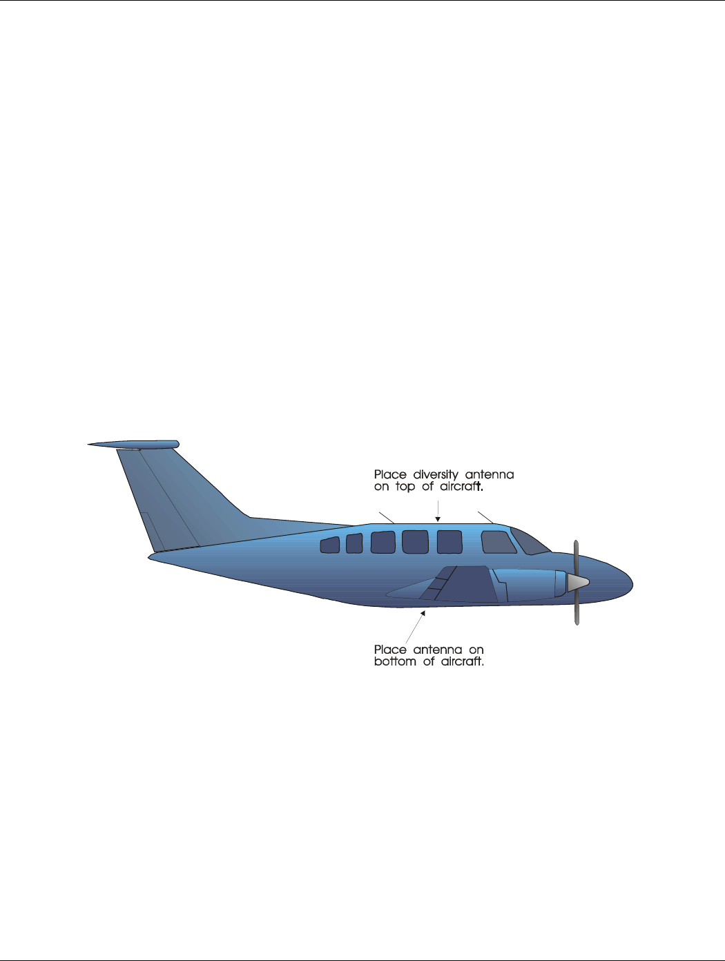
2.3.1 Location Considerations
Figure 2-1. Antenna Installation Considerations
A. The antenna (GARMIN P/N 010-10160-00) should be mounted away from major protrusions, such as
engine(s), propeller(s), and antenna masts. It should also be as far as practical from landing gear doors,
access doors, or other openings that could effect its radiation pattern.
B. The antenna should be mounted on the underside of the aircraft and in a vertical position when the
aircraft is in level flight. The diversity antenna should be mounted on the top of the aircraft.
C. Avoid mounting the antenna within three feet of the ADF sense antenna or any other communication
antenna and six feet from the DME antenna.
D. To prevent RF interference, the antenna must be physically mounted a minimum distance of three feet
from the GTX 330.

Page 2-2 GTX 330 Installation Manual
Rev. 1 190-00207-02
NOTE
If the antenna is being installed on a composite aircraft, ground planes must sometimes be
added. Conductive wire mesh, radials, or thin aluminum sheets embedded in the composite
material provide the proper ground plane allowing the antenna pattern (gain) to be maximized
for optimum transponder performance.
2.3.2 Antenna Installation
Install the antenna according to the antenna manufacturer’s instructions and FAA AC 43.13-2A.
2.3.3 Installation Approval Considerations for Pressurized Aircraft
Antenna and cable installations on pressurized cabin aircraft require FAA approved installation design and
engineering substantiation data whenever such installations incorporate alteration (penetration) of the cabin pressure
vessel by connector holes and/or mounting arrangements.
For needed engineering support pertaining to the design and approval of such pressurized aircraft antenna
installations, it is recommended that the installer proceed according to any of the following listed alternatives:
1. Obtain approved antenna installation design data from the aircraft manufacturer.
2. Obtain an FAA approved Supplemental Type Certificate (STC) pertaining to and valid for the subject
antenna installation.
3. Contact the FAA Aircraft Certification Office in the appropriate Region and request identification of FAA
Designated Engineering Representatives (DERs) who are authorized to prepare and approve the required
antenna installation engineering data.
4. Obtain FAA Advisory Circular AC-183C and select (and contact) a DER from the roster of individuals
identified thereunder.
5. Contact an aviation industry organization such as the Aircraft Electronics Association and request their
assistance.

GTX 330 Installation Manual Page 2-3
190-00207-02 Rev. 1
2.3.4 Antenna Cable Installation
When routing antenna cables, observe the following precautions:
•All cable routing should be kept as short as possible and as direct as possible.
•Avoid sharp bends.
•Avoid routing cables near power sources (e.g., 400 Hz generators, trim motors, etc.) or near power for
fluorescent lighting.
•Avoid routing cable near ADF antenna cable (allow at least a 12-inch separation).
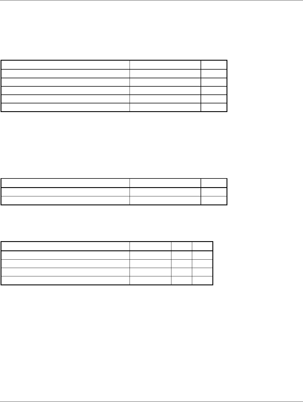
The following table lists examples of the recommended antenna cable vendors and the type of cable to be used for
specific lengths of cable. Any cable meeting specifications is acceptable for the installation. The maximum coaxial
cable attenuation at 1090 MHz must not exceed 1.5 dB.
Max. Length (feet) ECS Type MIL-C-17 Type RG Type
8.8 M17/128 RG400
10.0 3C142B
12.5 M17/112 RG304
17.0 311601 M17/127 RG393
21.0 311501
27.0 311201
41.0 310801
Supplier Information Vendor: Electronic
Cable Specialists
5300 W. Franklin Drive
Franklin, WI 53132
Tel: 800-327-9473
414-421-5300
Fax: 414-421-5301
MIL-C-17 types: See
current issue of
Qualified Products List
QPL-17.
RG types: See current
issue of Qualified
Products List QPL-17.
Page 2-4 GTX 330 Installation Manual
Rev. 1 190-00207-02
2.4 COOLING AIR
The GTX 330 meets all TSO requirements without forced air-cooling. (The application of forced air cooling to the
rear air nozzle of the GTX 330 provides beneficial cooling to the unit. The GTX 330 is designed to dissipate its
internal heat without the need of blowing air inside the unit.)
The GTX 330 was designed to handle a constant 450 PRF, with short periods of 1200 PRF. Rate limit is set at 1200
PRF. A typical radar site would interrogate the transponder once every 5 to 10 seconds for approximately 100 msec
at a 400 PRF rate. In very high traffic areas with multiple ground stations and TCAS traffic it is possible to have
long term PRF rates above 450 PRF. The GTX 330 measures the unit temperature and without forced air-cooling the
reply rate will be reduced to protect the transmitter from overheating.
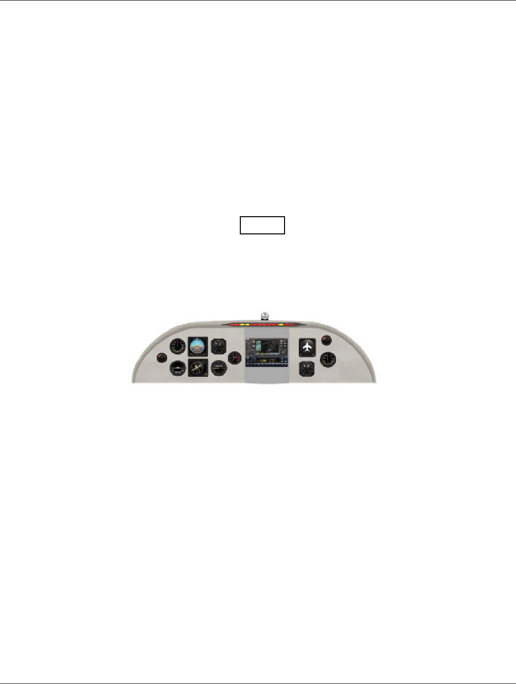
2.5 GTX 330 INSTALLATION
NOTE
Avoid installing the unit near heat sources. If this is not possible, insure that
additional cooling is provided. Allow adequate space for installation of cables and
connectors. The installer will supply and fabricate all of the cables. All wiring must
be in accordance with FAA AC 43.13-2A.
Figure 2-2 Unit Installation Considerations
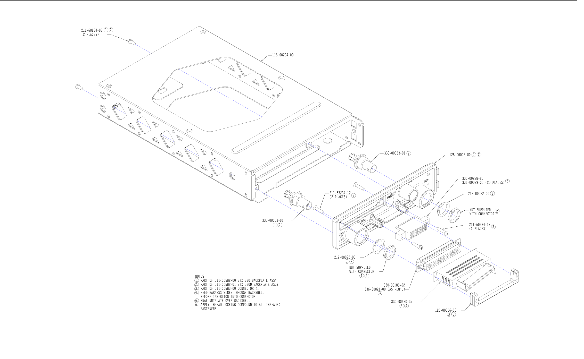
1. Assemble the connector/rack kit according to figure 4-2. Install the rack assembly according to the
dimensions given in figures 4-1 and paragraph 1.4.2 Physical Characteristics of the GTX 330. Mounting
brackets are not supplied due to the wide range of mounting configurations available. Suitable mounting
brackets may be fabricated from sheet metal or angle stock. To insure a sturdy mount, rear support for
the unit must be provided.
2. Looking at the bottom of the transponder, make sure the front lobe of the locking mechanism is in a
vertical position. This can be accomplished by using a 3/32” Allen wrench through the face plate.
3. Slide the unit into the rack until the front lobe of the unit touches the rack.
4. Turn the Allen wrench clockwise until unit is secured in the rack. Continue turning until tight. Do not
overtighten the screw.
5. To remove the unit from the rack, turn the 3/32” Allen wrench counterclockwise until it disengages from
the rack.
GTX 330 Installation Manual Page 3-1
190-00207-02 Rev. 1
3. INSTALLATION PROCEDURE
3.1 ANTENNA INSTALLATION
3.1.1 Antenna Installation
Install the antenna according to the antenna manufacturer’s instructions and FAA AC 43.13-2A.
3.1.2 Antenna Cable Connectors
The antenna cable requires a BNC connector at the antenna and a male BNC “Blindmate” connector
(P/N 330-00053-01, supplied with GTX 330 backplate assembly, 011-00582-00/01 at the transponder. Follow BNC
connector manufacturer instructions for assembly of the BNC connector.
3.2 ELECTRICAL CONNECTIONS
All electrical connections, except for the antenna, are made through a single, 62 pin D-subminiature connector.
Figure 2-1 defines the electrical characteristics of all input and output signals and identifies the cable requirements
for each signal. Required connector and associated hardware are supplied in the connector kit (P/N 011-00583-00).
See figures 4-1 and 4-2 for interconnect wiring diagrams.
CAUTION
Check wiring connections for errors before inserting the GTX 330 into the rack.
Incorrect wiring could cause internal component damage.
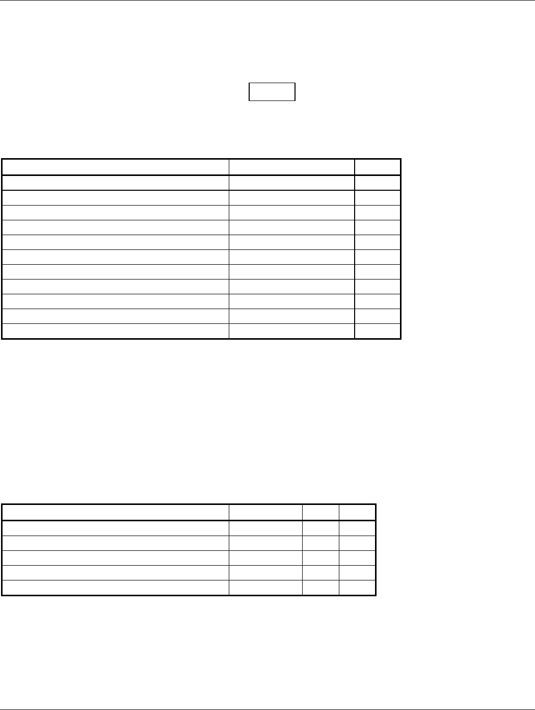
Pin Contact Part Numbers
62 pin connector (P3301)
Wire Gauge 22-28 AWG
GARMIN P/N 336-00021-00
Military P/N M39029/58-360
Recommended Crimp Tools
Wire Gauge 20-24 AWG
Hand Crimping
Tool
Positioner Insertion/
Extraction Tool
Military P/N M22520/2-01 M22520/2-08 M81969/1-02
Positronic 9507 9502-5 M81969/1-02
ITT Cannon 995-0001-584 995-0001-604 980-2000-426
AMP 601966-1 601966-5 91067-2
Daniels AFM8 K13-1 M24308/1-02
Astro 615717 615724 M81969/1-02
NOTES
1. Insertion/extraction tools from ITT Cannon are all plastic; others are plastic with metal tip.
2. Non-GARMIN part numbers shown are not maintained by GARMIN and consequently are subject to
change without notice.
3. All wires must be passed through the backshell before being assembled to connector.

Page 3-2 GTX 330 Installation Manual
Rev. 1 190-00207-02
3.4 POST INSTALLATION CHECKOUT
CAUTION
Be sure to check all aircraft control movements before flight is attempted to insure
that the wiring harness does not touch any moving part.
Verify proper operation of the transponder during a flight test under VFR conditions.
GTX 330 Installation Manual Page 3-5 (Page 3-6 blank)
190-00207-02 Rev 1
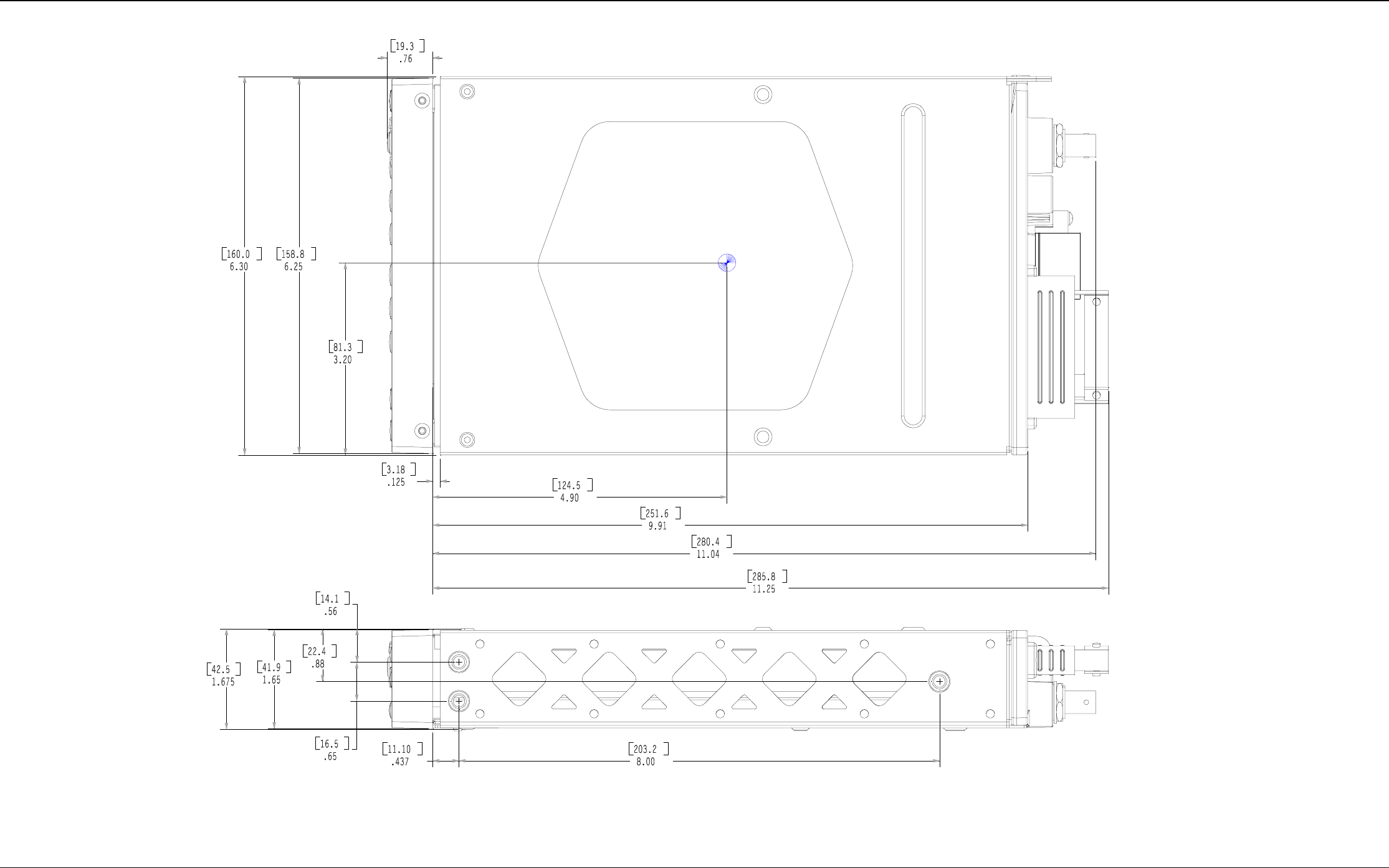
Figure 3-1 GTX 330 OUTLINE DRAWING
GTX 330 Installation Manual Page 3-7 (Page 3-8 blank)
190-00207-02 Rev 1
Figure 3-2 GTX 330 CONNECTOR/RACK ASSEMBLY DRAWING
GTX 330 Installation Manual Page 3-9 (Page 3-10 blank)
190-00207-02 Rev 1
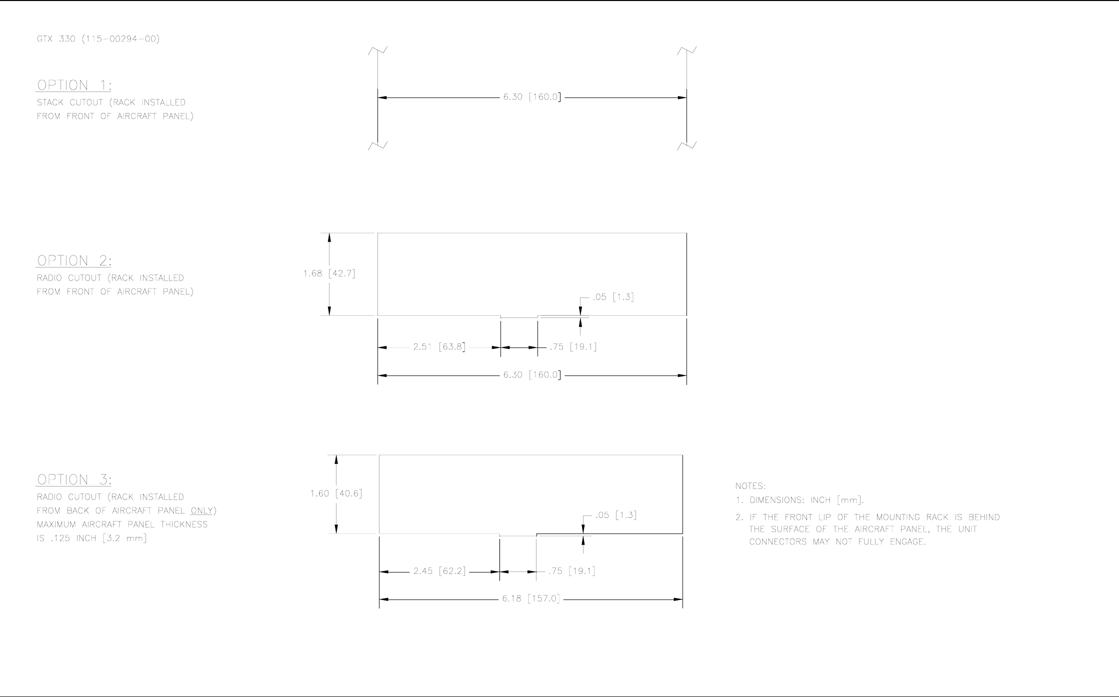
Figure 3-3 GTX 330 RECOMMENDED PANEL CUTOUT DIMENSIONS

GTX 330 Installation Manual Page 4-1
190-00207-02 Rev. 1
4. SYSTEM INTERCONNECTS
4.1 PIN FUNCTION LIST
4.1.1 J3301
123456789101112131415
222324252627282930313233343536
44464748495051
525354
5556
161718192021
373839404142
57
5859
6061
62
Figure 4-1. Rear Connector, J3301
Connector P3301
Pin Pin Name I/O
1 AVIONICS MASTER ON SELECT* In
2 ALTITUDE A1 In
3 ALTITUDE C2 In
4 ALTITUDE A2 In
5 ALTITUDE A4 In
6 ALTITUDE C4 In
7 ALTITUDE B1 In
8 ALTITUDE C1 In
9 ALTITUDE B2 In
10 ALTITUDE B4 In
11 ALTITUDE D4 In
12 EXTERNAL IDENT SELECT* In
13 EXTERNAL STANDBY SELECT* In
14 28 V LIGHTING BUS HI In
15 AUDIO OUT HI Out
16 AUDIO OUT LO Out
17 SQUAT SWITCH IN In
18 RESERVED --
19 ALTITUDE ALERT ANNUNCIATE* Out
20 RESERVED --
21 AIRCRAFT POWER In
22 RS 232 IN 1 In
23 RS 232 OUT 1 Out
24 RS 232 IN 2 In
25 RS 232 OUT 2 Out
26 ARINC 429 IN 3 A In
27 AIRCRAFT GROUND --
28 ARINC 429 OUT 2 B Out
29 ARINC 429 IN 3 B In
30 ARINC 429 OUT 2 A Out
31 EXTERNAL SUPPRESSION I/O I/O
32 ARINC 429 IN 1 A In
33 ARINC 429 IN 2 A In
Table 4-1. P3301 Pin Assignments

Page 4-2 GTX 330 Installation Manual
Rev. 1 190-00207-02
Connector P3301, continued
Pin Pin Name I/O
34 ARINC 429 OUT 1 B Out
35 ARINC 429 IN 1 B In
36 ARINC 429 IN 2 B In
37 ARINC 429 OUT 1 A Out
38 TEMPERATURE PROBE 1 OUT Out
39 TEMPERATURE PROBE 1 IN In
40 RESERVED --
41 TEMPERATURE PROBE 2 OUT Out
42 AIRCRAFT POWER In
43 AIRCRAFT GROUND --
44 TEMPERATURE PROBE 2 IN In
45 14 V/5 V LIGHTING BUS HI In
46 TIS CONNECT SELECT* In
47 RESERVED --
48 ARINC 429 IN 4 A In
49 ARINC 429 IN 4 B In
50 ALTITUDE COMMON (GROUND) In
51 RESERVED --
52 RESERVED --
53 RESERVED --
54 RESERVED --
55 RESERVED --
56 RESERVED --
57 RESERVED --
58 RESERVED --
59 RESERVED --
60 RESERVED --
61 RESERVED --
62 SWITCHED POWER OUT Out
Table 4-1. P3301 Pin Assignments (Cont’d)
* Ground to activate.
Refer to Figure 4-1 on page 4-5 for GTX 330 interconnect wiring diagram.
GTX 330 Installation Manual Page 4-3
190-00207-02 Rev. 1
4.2 Power and Lighting Function
Power Input requirements and Lighting Bus input are listed in the following tables. The power-input pins accept
11-33 VDC. Switched Power Out is a power source available for devices such as a remote digital altitude encoder.
4.2.1 Aircraft Power
PIN NAME CONNECTOR/PIN I/O
AIRCRAFT POWER P3301 21 In
AIRCRAFT POWER P3301 42 In
SWITCHED POWER OUT P3301 62 Out
AIRCRAFT GROUND P3301 27 --
AIRCRAFT GROUND P3301 43 --
Table 4-2. Aircraft Power Pin Assignments
4.2.2 Lighting Bus
The GTX 330 unit can be configured to track a 28 VDC, 14 VDC, 5 VDC or 5 VAC lighting bus using these inputs.
The GTX 330 can also automatically adjust for ambient lighting conditions based on the photocell. Refer to sections
5.2.5. and 5.2.6.
PIN NAME CONNECTOR/PIN I/O
14 V/5 V LIGHTING BUS HI P3301 45 In
28 V LIGHTING BUS HI P3301 14 In
Table 4-3. Aircraft lighting Pin Assignments
4.3 Temperature Inputs
Pin Name Connector Pin I/O
TEMPERATURE PROBE 1 OUT P3301 38 Out
TEMPERATURE PROBE 1 IN P3301 39 In
TEMPERATURE PROBE 2 OUT P3301 41 Out
TEMPERATURE PROBE 2 IN P3301 44 In
Table 4-4. Temperature Probe Pin Assignments
Temperature is used for Density Altitude computations. Probe #1 is for a voltage mode sensor. Probe #2 is for a
current mode sensor. Refer to section 5.2.11.
Page 4-4 GTX 330 Installation Manual
Rev. 1 190-00207-02
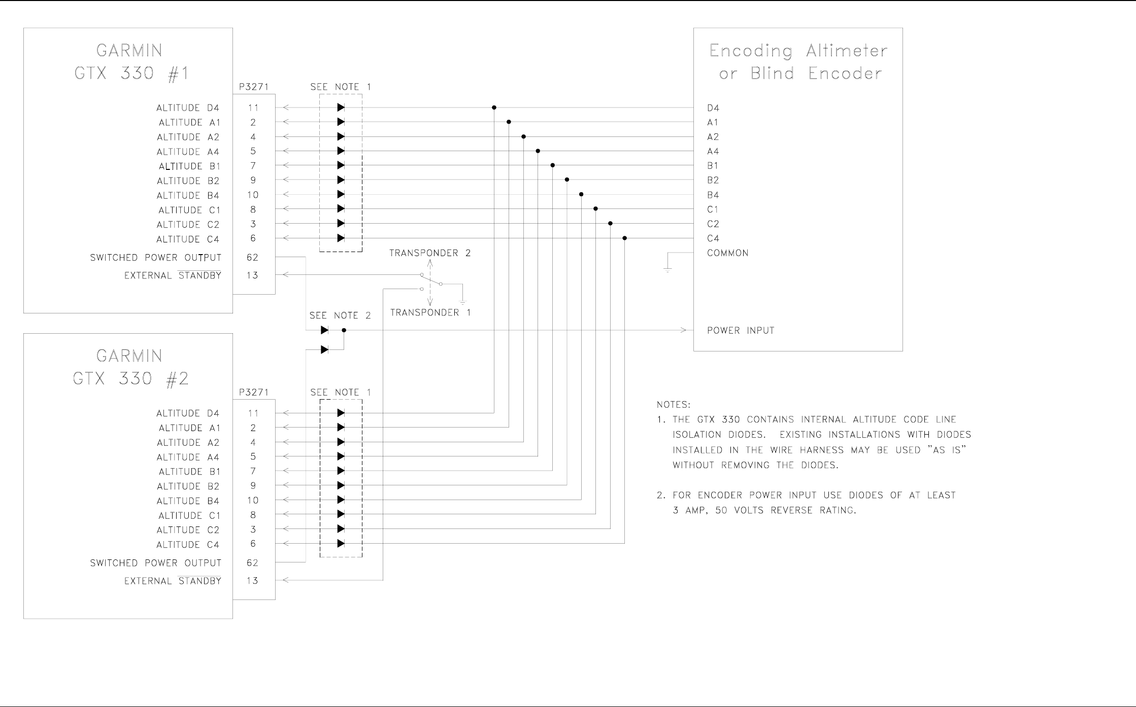
4.4 Altitude Function
Altitude inputs are considered active if either the voltage to ground is < 1.9 V or the resistance to ground is < 375 Ω.
These inputs are considered inactive if the voltage to ground is 11-33 VDC.
NOTE
The GTX 330 contains internal altitude code line isolation diodes to prevent the
unit from pulling the encoder lines to ground when the transponder is turned off.
Pin Name CONNECTOR/PIN I/O
ALTITUDE D4 P3301 11 In
ALTITUDE A1 P3301 2 In
ALTITUDE A2 P3301 4 In
ALTITUDE A4 P3301 5 In
ALTITUDE B1 P3301 7 In
ALTITUDE B2 P3301 9 In
ALTITUDE B4 P3301 10 In
ALTITUDE C1 P3301 8 In
ALTITUDE C2 P3301 3 In
ALTITUDE C4 P3301 6 In
ALTITUDE COMMON P3301 50 --
Table 4-5. Encoded Altitude Pin Assignments
4.4.1 Altimeter Calibration and Checkout
Refer to section 5.2.13 for the gray code altitude checkout.
4.4.2 Altimeter Interconnect, Dual GTX 330 Units
Refer to Figure 4-2 on page 4-7 for Dual GTX 330 altimeter interconnect.
4.5 Discrete Inputs
Pin Name Connector Pin I/O
EXTERNAL IDENT SELECT P3301 12 In
EXTERNAL STANDBY SELECT* P3301 13 In
SQUAT SWITCH IN P3301 17 In
ALTITUDE ALERT ANNUNCIATE* P3301 19 Out
TIS CONNECT SELECT* P3301 46 In
Table 4-6. Discrete Inputs Pin Assignments
These inputs are considered active if either the voltage to ground is < 1.9 V or the resistance to ground
is < 375 Ω. These inputs are considered inactive if the voltage to ground is 11-33 VDC.
EXTERNAL IDENT SELECT (remote IDENT) is a momentary input. Refer to sections 5.2.10. and 5.2.14 for the
squat switch.
GTX 330 Installation Manual Page 4-5
190-00207-02 Rev. 1
4.6 Serial Data Electrical Characteristics
Pin Name Connector Pin I/O
RS 232 OUT 1 P3301 23 Out
RS 232 IN 1 P3301 22 In
RS 232 OUT 2 P3301 23 Out
RS 232 IN 2 P3301 24 In
Table 4-7. RS 232 Pin Assignments
The RS-232 outputs conform to EIA Standard RS-232C with an output voltage swing of at least ± 5 V when driving a
standard RS-232 load. Refer to Figure 4-2 on page 4-7 for the RS-232 serial data interconnect. Refer to sections
5.2.9. and 5.2.16.
Pin Name Connector Pin I/O
ARINC 429 OUT 1A P3301 37 Out
ARINC 429 OUT 1B P3301 34 Out
ARINC 429 IN 1A P3301 32 In
ARINC 429 IN 1B P3301 35 In
ARINC 429 IN 2A P3301 33 In
ARINC 429 IN 2B P3301 36 In
ARINC 429 OUT 2A P3301 30 Out
ARINC 429 OUT 2B P3301 28 Out
ARINC 429 IN 3A P3301 26 In
ARINC 429 IN 3B P3301 29 In
ARINC 429 IN 4A P3301 48 In
ARINC 429 IN 4B P3301 49 In
Table 4-8. ARINC 429 Pin Assignments
The ARINC 429 outputs conform to ARINC 429 electrical specifications when loaded with up to 5 standard ARINC
429 receivers. Refer to sections 5.2.8. and 5.2.17.

Page 4-6 GTX 330 Installation Manual
Rev. 1 190-00207-02
This page intentionally left blank
GTX 330 Installation Manual Page 4-5 (Page 4-6 blank)
190-00207-02 Rev 1
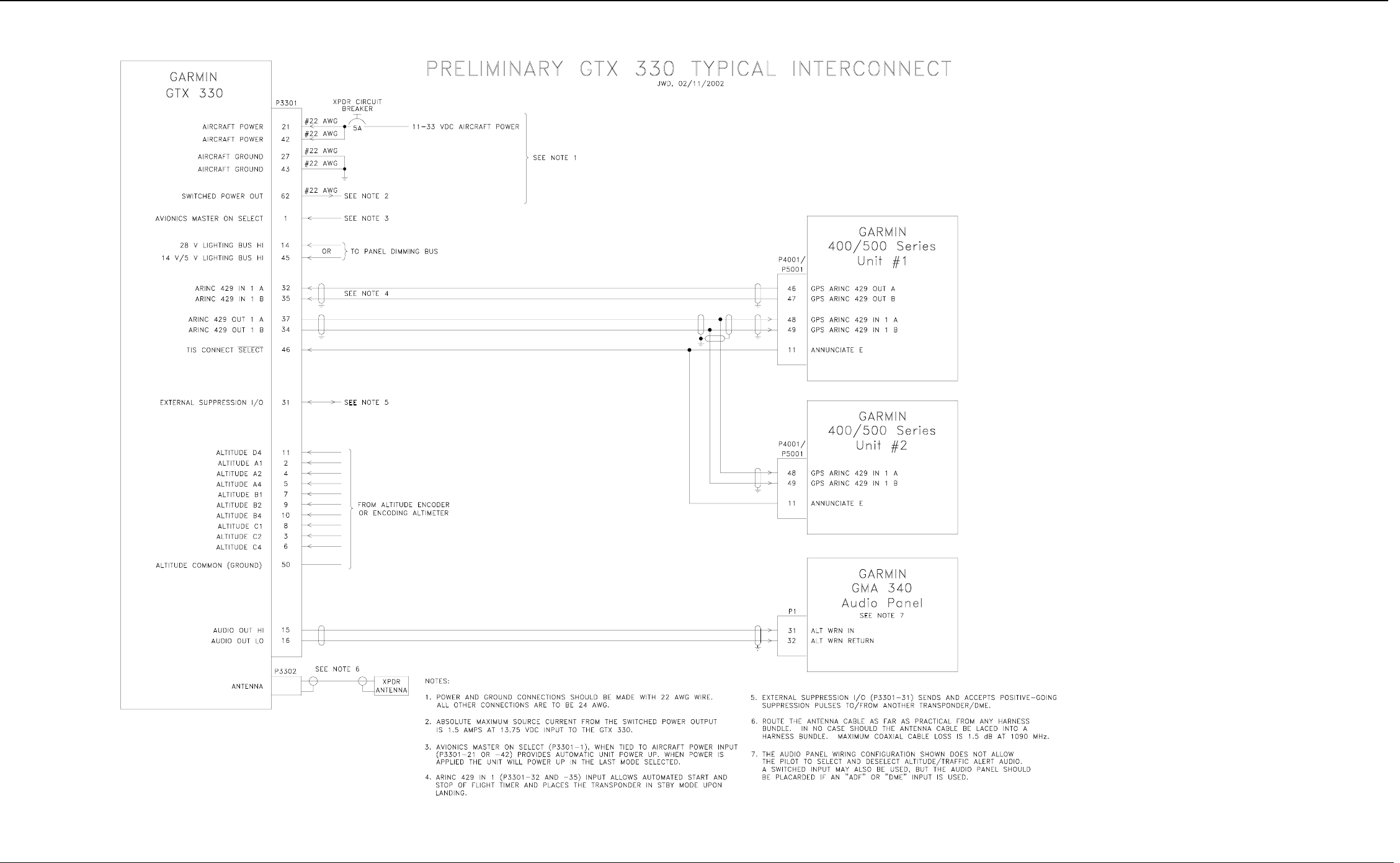
Figure 4-1 GTX 330 INTERCONNECT WIRING DIAGRAM
GTX 330 Installation Manual Page 4-7 (Page 4-8 blank)
190-00207-02 Rev 1
Figure 4-2 DUAL TXP INTERCONNECT WIRING DIAGRAM, ENCODING ALTITUDE CONNECTIONS
GTX 330 Installation Manual Page 5-1
190-00207-02 Rev. 1
5. POST INSTALLATION CONFIGURATION AND CHECKOUT PROCEDURE
5.1 OPERATION
NOTE
The coverage you can expect from the GTX 330 is limited to line of sight. Low altitude or
antenna shielding by the aircraft itself may result in reduced range. Range can be improved
by climbing to a higher altitude. It may be possible to minimize antenna shielding by
locating the antenna where dead spots are only noticed during abnormal flight attitudes.
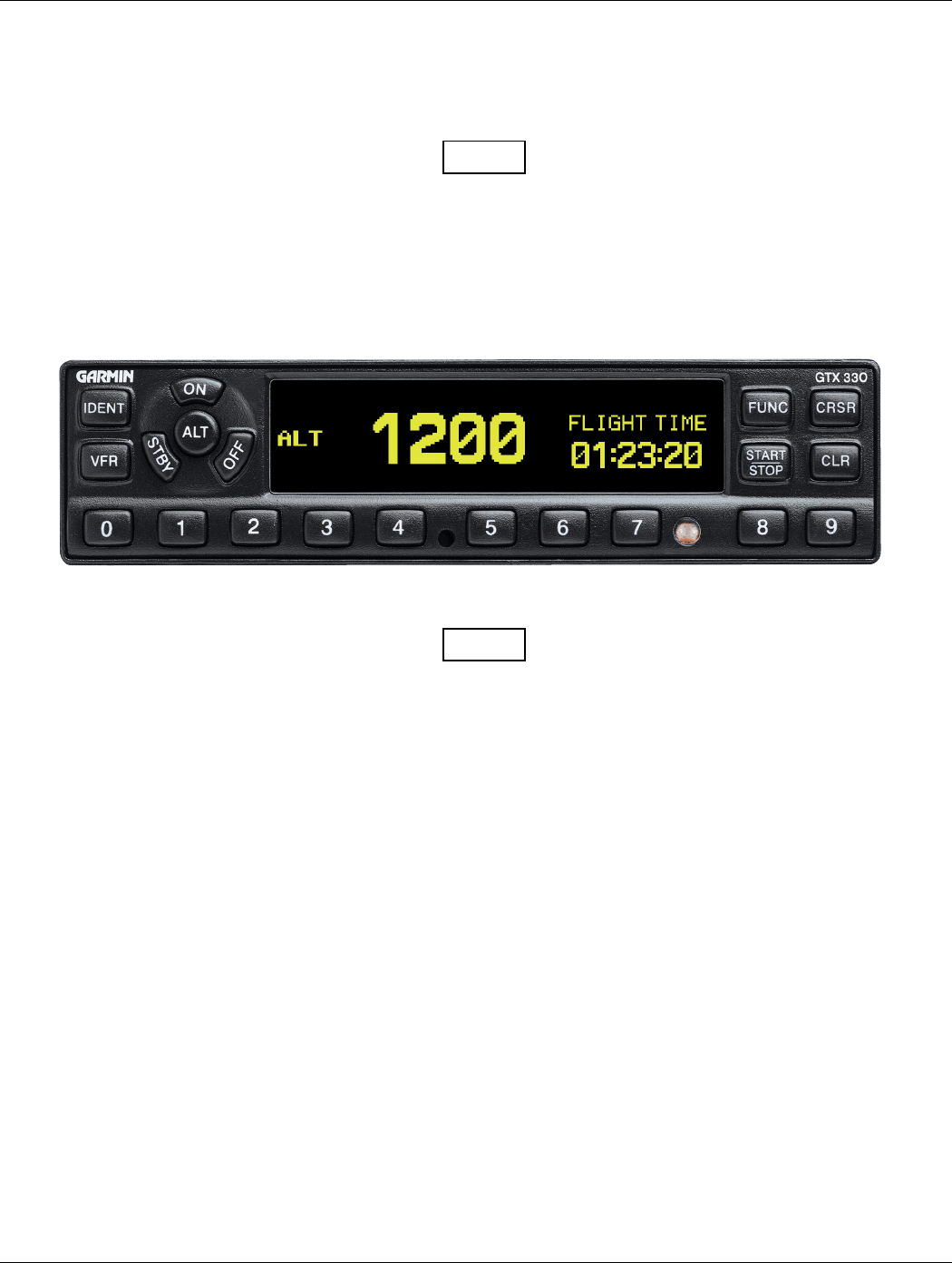
Figure 5-1. GTX 330 Front Panel
NOTE
The GTX 330 should be turned off before starting aircraft engine(s).
5.1.1 Function Selector Switches
The function selection switches are:
• OFF Powers off the GTX 330. Pressing the STBY, ON or ALT key powers on the transponder
displaying the last active identification code.
• STBY Selects the standby mode. When in standby mode, the transponder will not reply to any
interrogations.
• ON Selects Mode A and Mode S. In this mode, the transponder replies to Mode A, Mode C and Mode
S interrogations, as indicated by the Reply Symbol (“®”), but the replies do not include altitude
information.
• ALT Selects Mode A, Mode C and Mode S. In ALT mode, the transponder replies to identification,
altitude and Mode S interrogations as indicated by the Reply Symbol (“®”). Replies to altitude
interrogations include the standard pressure altitude received from an external altitude source,
which is not adjusted for barometric pressure. The ALT mode may be selected in aircraft not
equipped with an optional altitude encoder; however, the reply signal will not include altitude
information.

Page 5-2 GTX 330 Installation Manual
Rev. 1 190-00207-02
NOTE
Any time the function switch is in the ON or ALT position the transponder becomes an
active part of the Air Traffic Control Radar Beacon System (ATCRBS). The
transponder also responds to interrogations from TCAS equipped aircraft.
• IDENT Pressing the IDENT key activates the Special Position Identification (SPI) Pulse for 18 seconds,
identifying the transponder return from others on an air traffic controller’s screen. During the
IDENT period the word ‘IDENT’ appears in the upper left corner of the display.
• VFR Sets the transponder code to the pre-programmed VFR code selected in Configuration Mode (Set
to 1200 at the factory). Pressing the VFR key again will restore the previous identification code.
• FUNC Changes the page shown on the right side of the display. Display data includes Pressure
Altitude, Flight Time, Count Up and Count Down timers. In the Configuration Mode, steps
through the function pages.
• START/ STOP Starts and stops the Count Up, Count Down and Flight timers. In configuration mode,
steps through functions in reverse.
• CRSR Initiates entry of the starting time for the Count Down timer and cancels transponder code entry.
Selects changeable fields in Configuration Mode.
• CLR Resets the Count Up, Count Down and Flight timers. Cancels the previous keypress during code
selection and Count Down entry. Used in Configuration Mode.
• 8 Reduces Contrast and Display Brightness when the respective fields are displayed and enters the
number eight into the Count Down timer. Used in Configuration Mode.
• 9 Reduces Contrast and Display Brightness when the respective fields are displayed and enters the
number eight into the Count Down timer. Used in Configuration Mode.
5.1.2 Code Selection
Code selection is done with eight keys (0 – 7) providing 4,096 active identification codes. Pushing one of these keys
begins the code selection sequence. The new code is not activated until the fourth digit is entered. Pressing the CLR
key moves the cursor back to the previous digit. Pressing the CLR key when the cursor is on the first digit of the
code, or pressing the CRSR key during code entry, removes the cursor and cancels data entry, restoring the previous
code. You may press the CLR key up to five seconds after code entry is complete to return the cursor to the fourth
digit. The numbers 8 and 9 are not used for code entry, only for entering a Count Down time, contrast and display
brightness and in the Configuration Mode.
NOTE
The selected identification code should be entered carefully, either one assigned by air
traffic control for IFR flight or an applicable VFR transponder code.

GTX 330 Installation Manual Page 5-3
190-00207-02 Rev. 1
• Important Codes:
1200 The VFR code for any altitude in the US (Refer to ICAO standards elsewhere)
7000 The VFR code commonly used in Europe (Refer to ICAO standards)
7500 Hijack code (Aircraft is subject to unlawful interference)
7600 Loss of communications
7700 Emergency
7777 Military interceptor operations (Never squawk this code)
0000 Military use (Not enterable)
Avoid selecting code 7500 and all codes in the 7600-7777 range. These codes trigger special indicators in automated
facilities. An aircraft’s transponder code is used for ATC tracking purposes, therefore exercise care when making
routine code changes.
5.1.3 Function Display
PRESSURE ALT Displays the altitude data supplied to the GTX 330 in feet, hundreds of feet (i.e., flight
level), or meters, depending on configuration.
FLIGHT TIME Displays the Flight Time, controlled by the START/STOP key or by one of three
airborne sources (squat switch, GPS ground speed recognition or altitude increase) as
configured during installation. The timer begins when the GTX 330 determines that the
aircraft is airborne.
ALTITUDE MONITOR Activates a voice alarm and warning annunciator when altitude limit is
exceeded.
COUNT UP TIMER Controlled by START/STOP and CLR keys.
COUNT DOWN TIMER Controlled by START/STOP, CLR, and CRSR keys. The initial Count Down
time is entered with the 0 – 9 keys.
CONTRAST This page is only displayed if manual contrast mode is selected in Configuration Mode.
Contrast is controlled by the 8 and 9 keys .
DISPLAY This page is only displayed if manual backlighting mode is selected in Configuration Mode.
Backlighting is controlled by the 8 and 9 keys.

Page 5-4 GTX 330 Installation Manual
Rev. 1 190-00207-02
5.2 CONFIGURATION PAGES
Holding down the FUNC key and pressing the ON key provides access to the configuration pages. The FUNC key
sequences forward through the configuration pages. The START/STOP button reverses through the pages, stopping
at the Menu page. The CRSR key will highlight selectable fields on each page. When a field is highlighted, numeric
data entry will be performed with the 0 – 9 keys and list selections will be performed with the 8 or 9 keys. Press the
CRSR key to accept changes. Pressing the FUNC key moves on to the next configuration page without saving the
changes. Changes made through the configuration pages are stored in EEPROM memory. To exit the configuration
pages, turn the power off and then on again (without holding the FUNC key).
The configuration page sequence is as follows (menu categories are listed in parenthesis):
• ‘Jump To’ Menu
• Audio and Messages (first and second pages)
• Traffic Information
• Display Mode
• Display Backlight
• Key Backlight
• Contrast
• ARINC 429 Input #1 (first I/O Configuration page)
• ARINC 429 Input #2 (second I/O Configuration page)
• ARINC 429 Output
• RS232 Input
• Operation Configuration #1 (first Aircraft Configuration page)
• Operation Configuration #2 (second Aircraft Configuration page)
• Temperature
• Aircraft Address
• Flight ID
• Aircraft Type
• Squat Switch Setup
• Gray Code Input
• External Switch State
• Analog Input
• RS232 Input Display
• ARINC 429 Input Display #1
• ARINC 429 Input Display #2.
GTX 330 Installation Manual Page 5-5
190-00207-02 Rev. 1
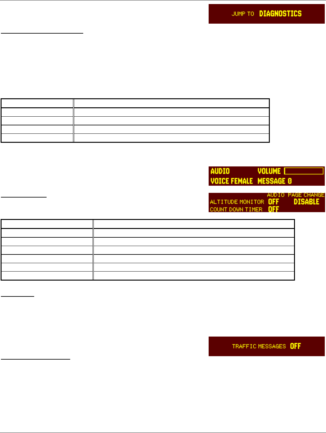
5.2.1 Configuration Menu Page
CONFIGURATION MENU
The JUMP TO menu page provides the capability to select a configuration mode starting page without having to step
through all of the pages. Select the desired section with the CRSR key and sequence through with the 8 and 9 keys.
Jump to the selection by pressing the CRSR key again with the desired selection highlighted.
The FUNC key steps to the next configuration page, after which the START/STOP key reverses until stopping at the
Menu page.
Selection Description
DIAGNOSTICS Jumps to Gray Code Input page.
DISPLAY/AUDIO Jumps to Audio Volume page.
I/O CONFIG Jumps to ARINC 429 INPUT #1 page.
ACFT CONFIG Jumps to configuration Operation Configuration #1 page.
5.2.2 AUDIO MODE Pages
AUDIO MODE
Selection Description
VOICE (MALE FEMALE) Sets the voice to male or female. Default is male voice.
VOLUME Volume is adjusted from 0 (default) to maximum with the 8 or 9 key.
MESSAGE (0-9) Selected tones and messages.
ALTITUDE MONITOR Off, tone or message.
COUNT DOWN TIMER Off, tone or message.
DISABLE Messages either enabled or disabled.
MESSAGE
Message “0” is an on-off beeping tone. Message “1” through “5” are selected tones messages.
5.2.3 TRAFFIC INFORMATION PAGE
TRAFFIC MESSAGES
Sets the Traffic Messages to tone, Message or Off. Traffic Information Services (TIS) provides notification of close
proximity traffic.
CONFIGURATION MENU Page
AUDIO MODE (First) Page
AUDIO MODE (Second) Page
TRAFFIC INFORMATION Page
Page 5-6 GTX 330 Installation Manual
Rev. 1 190-00207-02
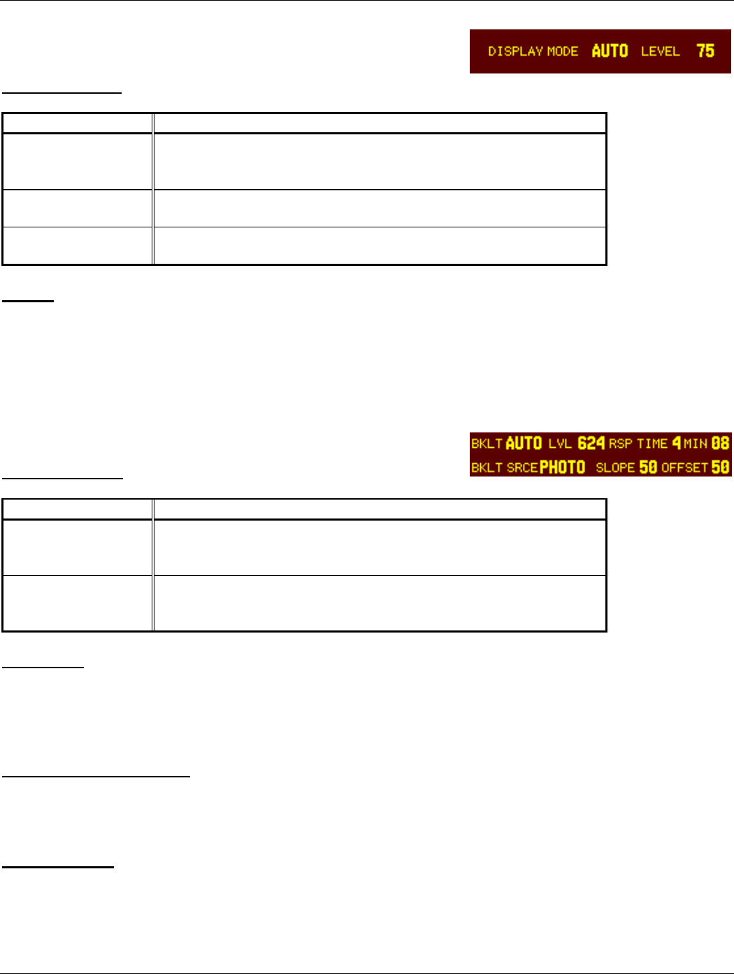
5.2.4 DISPLAY MODE PAGE
DISPLAY MODE
Selection Description
AUTO (Automatic) DEFAULT. The display will automatically change between Positive
mode (during the day) and Negative mode (at night), depending on the
ambient light level received by the photocell.
NGTV (Negative) The display will always be light characters on a black background,
regardless of ambient lighting.
PSTV (Positive) The display will always be black characters on a light background,
regardless of ambient lighting.
LEVEL
Sets the ambient light level for AUTO mode to change between negative and positive display. The higher the
number, the brighter the ambient light level to change over. This field has a range of 0 (zero) to 99, and is set to 75 at
the factory.
5.2.5 DISPLAY BACKLIGHT Page
BKLT (Backlight)
Selection Description
MAN (Manual) Display backlighting is controlled manually by the pilot on the
GTX 330 DISPLAY page. No backlight parameters can be entered
when the manual mode is selected.
AUTO (Automatic) DEFAULT. Display backlighting is automatically controlled, based
on the parameters entered on this configuration page. When AUTO is
selected, the DISPLAY page does not appear to the pilot.
LVL (Level)
Shows the current level of display backlighting, based on the lighting input source (lighting bus voltage, or the
ambient light if the source is PHOTO) and the settings on this configuration page. This field has a range of 0 (zero)
to 999, but is not a user-entered field (display only).
RSP TIME (Response Time)
Sets the speed with which the brightness responds to ambient light changes (only for AUTO backlight mode). The
higher the number, the slower the display responds. This field has a range of 3 to 7, and is set to 4 at the factory.
MIN (Minimum)
Sets the minimum brightness of the display. The higher the number, the brighter the minimum brightness. Display
minimum brightness has a range of 0 (zero) to 99, and is set to 8 at the factory. It is prudent to verify that display
lighting characteristics match those of other equipment in the panel under night lighting conditions.
DISPLAY MODE Page
DISPLAY BACKLIGHT Page
GTX 330 Installation Manual Page 5-7
190-00207-02 Rev. 1
BKLT SRCE (Backlight Source)
Selection Description
PHOTO (Photocell) DEFAULT. Backlight level is determined by the ambient light level
as measured by the photocell on the GTX 330.
14V Backlight level tracks a 14 volt DC aircraft lighting bus.
28V Backlight level tracks a 28 volt DC aircraft lighting bus.
5V Backlight level tracks a 5 volt DC aircraft lighting bus.
NOTE
If a lighting bus (any selection other than PHOTO) is selected, and the lighting bus control is
turned to its minimum (daytime) setting, the display brightness will track the GTX 330 photocell.
SLOPE
Sets the sensitivity of the display brightness to changes in the input level. The higher the number, the brighter the
display will be for a given increase in the input level. This field has a range of 0 (zero) to 99, and is set to 50 at the
factory.
OFFSET
Adjusts the lighting level up or down for any given input level. This field has a range of 0 (zero) to 99, and is set to
50 at the factory. This may also be used to match lighting curves with other equipment in the panel.
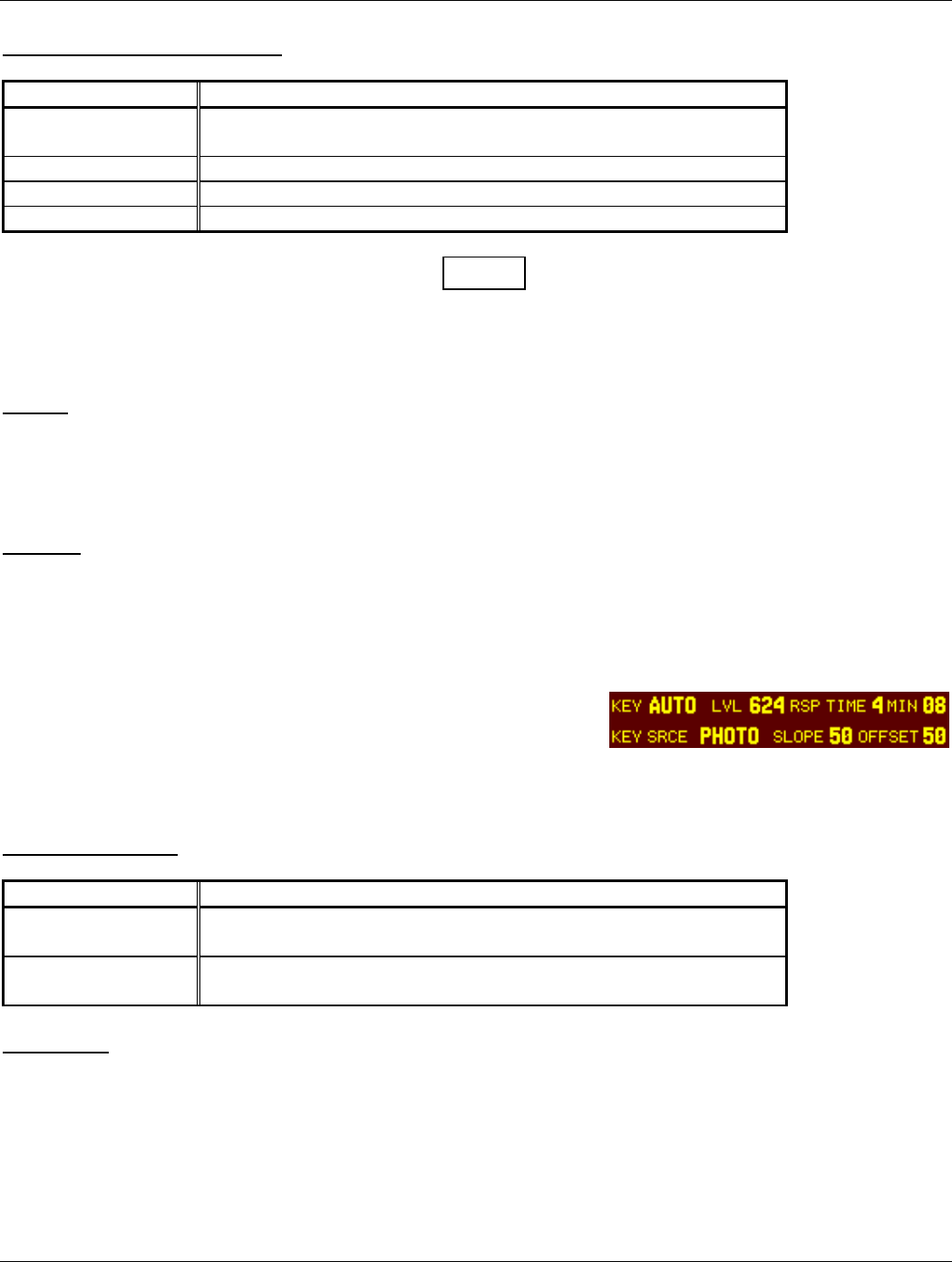
5.2.6 KEY LIGHTING Page
The key lighting mode is always the same as the display backlight mode,
so the mode must be changed on the Display Backlight configuration
page. If the lighting mode is AUTO, then the key lighting parameters
can be edited on this page.
KEY (Key Lighting)
Selection Description
MAN (Manual) Key lighting is controlled manually by the pilot on the GTX 330
DISPLAY page.
AUTO (Automatic) Key lighting is automatically controlled based on the parameters
entered on this configuration page.
LVL (Level)
Shows the current level of key lighting, based on the lighting input source (lighting bus voltage, or the ambient light
if the source is PHOTO) and the settings on this configuration page. This field has a range of 0 (zero) to 999, but is
not a user-entered field (display only).
KEY LIGHTING Page
Page 5-8 GTX 330 Installation Manual
Rev. 1 190-00207-02
RSP TIME (Response Time)
Sets the speed with which the brightness responds to ambient light changes (only for AUTO key lighting mode). The
higher the number, the slower the key lighting responds. This field has a range of 3 to 7, and is set to 4 at the factory.
MIN (Minimum)
Sets the minimum brightness of the key lighting. The higher the number, the brighter the minimum brightness. Key
lighting minimum brightness has a range of 0 (zero) to 99, and is set to 8 at the factory. It is prudent to verify that
key lighting characteristics match those of other equipment in the aircraft panel under night lighting conditions.
KEY SRCE (Key Lighting Source)
Selection Description
PHOTO (Photocell) DEFAULT. Key lighting level is determined by the ambient light
level as measured by the photocell on the GTX 330.
14V Backlight level tracks a 14 volt DC aircraft lighting bus.
28V Backlight level tracks a 28 volt DC aircraft lighting bus.
5V Backlight level tracks a 5 volt DC aircraft lighting bus.
SLOPE
Sets the sensitivity of the key lighting brightness to changes in the input level. The higher the number, the brighter
the key lighting will be for a given increase in the input level. This field has a range of 0 (zero) to 99, and is set to 50
at the factory.
OFFSET
Adjusts the key lighting level up or down for any given input level. This field has a range of 0 (zero) to 99, and is set
to 50 at the factory. This may also be used to match lighting curves with other equipment in the panel.
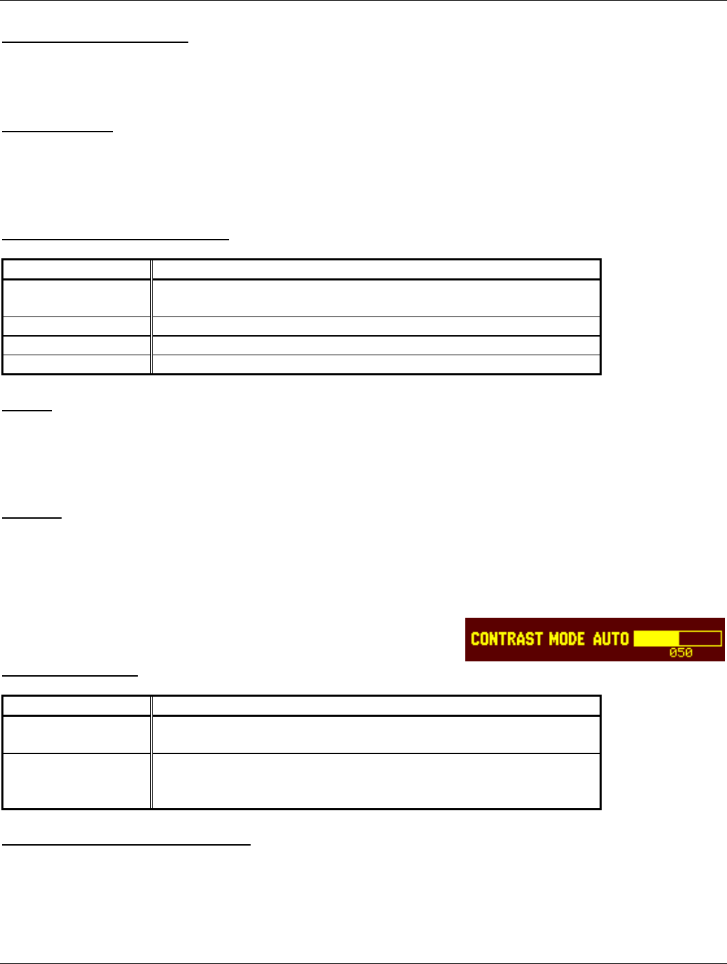
5.2.7 CONTRAST MODE Page
CONTRAST MODE
Selection Description
MAN (Manual) The display contrast is manually adjusted either here or by the pilot
using the GTX 330 CONTRAST page.
AUTO (Automatic) DEFAULT. The display contrast is automatically compensated for
temperature and other factors. An offset can be entered in the contrast
level adjustment described below.
CONTRAST LEVEL ADJUSTMENT
This is a “slider” bar graph control. Use the 8 key to move the graph to the left, decreasing the numbers and contrast
level. Use the 9 key to move it to the right, increasing the numbers and contrast level. It is set to 50% at the factory.
In manual contrast mode, this is a direct adjustment of the display contrast. In automatic contrast mode, this adjusts
the offset to the automatically compensated contrast.
CONTRAST Page
GTX 330 Installation Manual Page 5-9
190-00207-02 Rev. 1
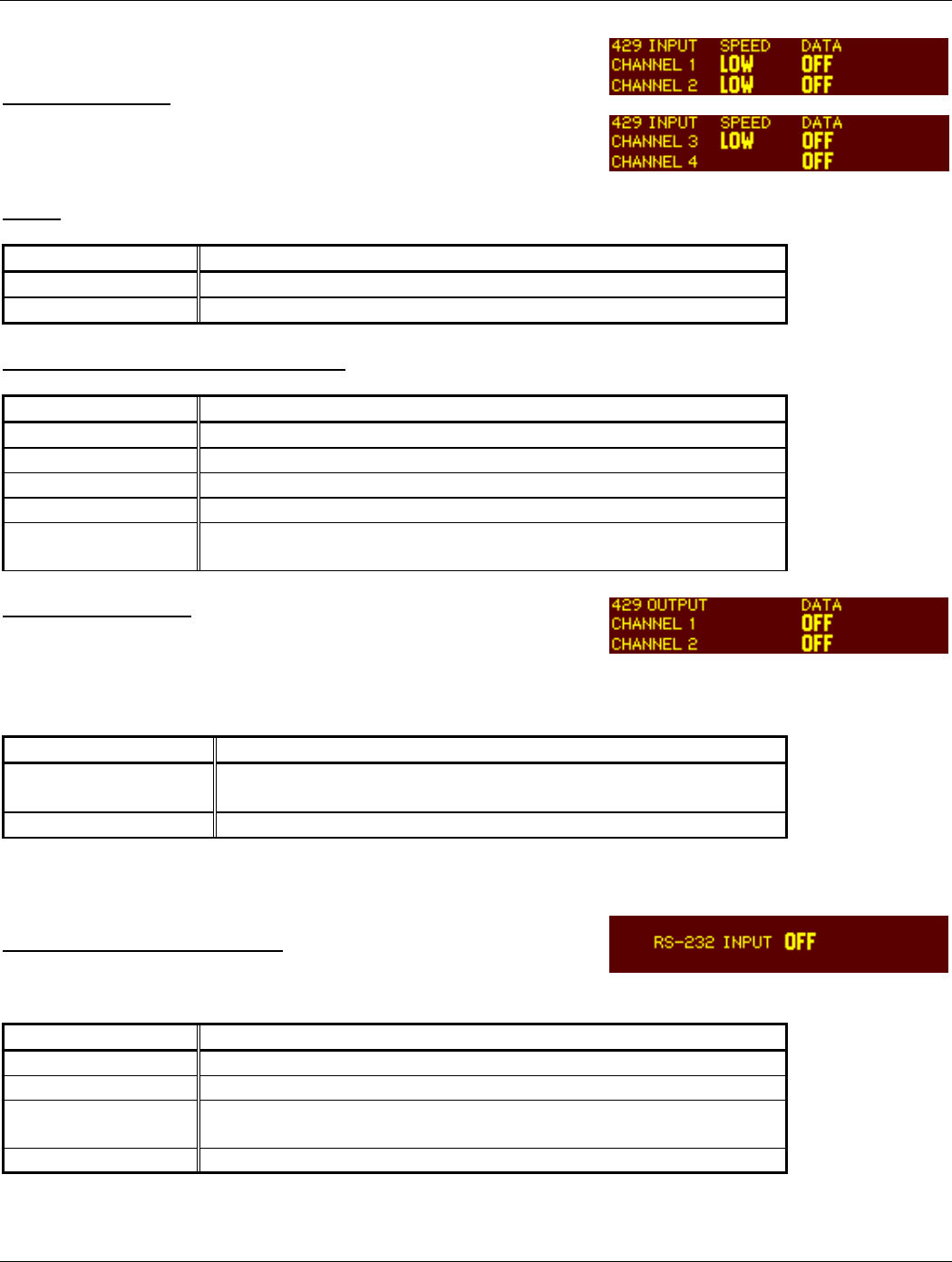
5.2.8 ARINC 429 CONFIGURATION Pages
ARINC 429 INPUT
The ARINC 429 INPUT Pages configure the ARINC 429 input ports.
Each port can be configured independently for the desired function(s).
SPEED
Selection Description
Low Standard low-speed ARINC 429 (nominally 12.5 kilobits per second).
High High-speed ARINC 429 (nominally 100 kilobits per second).
INPUT DATA 1, DATA 2 DATA 3, DATA 4
Selection Description
OFF No unit connected to this ARINC 429 input.
GPS Selected waypoint information.
Airdata Altitude, temperature and speed information.
AHRS Atitude, heading, temperature, and speed information.
EFIS/Airdata Selected course, heading, and joystick waypoint and speed
information.
ARINC 429 OUTPUT
The ARINC 429 OUTPUT Pages configure the ARINC 429 output ports.
Each port can be configured independently for the desired function(s).
Selection Description
CHANNEL 1 (SPEED
and DATA)
DATA SOURCE: AIRINC 735, GARMIN or OFF. DEFAULTS to
OFF.
CHANNEL 2 (DATA) DATA SOURCE: ADLP or OFF. DEFAULTS to OFF.
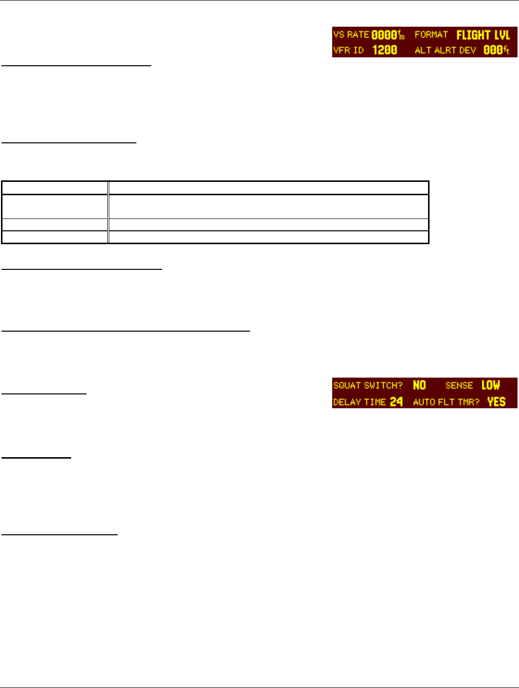
5.2.9 RS 232 INPUT PAGE
RS 232 INPUT (Altitude Source)
This is the electrical source for the GTX 330 altitude input.
Selection Description
OFF DEFAULT. OFF. The altitude code input is not from a 429 source.
ICARUS RS-232 serial altitude from an Icarus Instruments 3000.
SHADIN-ADC RS-232 serial altitude from a Shadin 9628XX-X family of Air Data
Computers and Fuel/Air Data Computers.
SHADIN-ALT RS-232 serial altitude from a Shadin 8800T, 9000T, 9200T.
ARINC 429 INPUT (First) Page
ARINC 429 INPUT (Second) Page
ARINC 429 OUTPUT Page
RS 232 INPUT Page
Page 5-10 GTX 330 Installation Manual
Rev. 1 190-00207-02
5.2.10 OPERATION CONFIGURATION PAGES
VS RATE (Vertical Speed Rate)
This field is the typical vertical speed for climb/descent of the aircraft. This number determines when a climb or
descent arrow is displayed on the PRESSURE ALT page of the GTX 330. The range is 0 (zero) feet per minute to
9999 feet per minute. It is set to 500 fpm at the factory.
FORMAT (Altitude Format)
This field determines how the pressure altitude will be shown on the GTX 330 display.
Selection Description
FLIGHT LVL
(Flight Level)
DEFAULT. The pressure altitude is displayed in hundreds of feet. For
example, a pressure altitude of 12,300 feet is displayed as “FL 123”.
FEET Pressure altitude is displayed in feet.
METERS Pressure altitude is displayed in meters.
VFR ID (VFR Transponder Code)
This field is the four-digit code that will be selected when the user presses the GTX 330 VFR key. In the United States, 1200 is
the VFR code for any altitude. It is set to 1200 at the factory.
ALTITUDE ALERT DEVIATION (Altitude Format)
This field determines the amount of altitude difference from selected altitude to generate an altitude alert deviation.
SQUAT SWITCH
The GTX 330 Flight Timer and the Auto Standby feature may be based
on the squat switch state. The squat switch field may be set to either YES or NO.
DELAY TIME
This is the number of seconds the aircraft must be on the ground before the AUTO STANDBY feature automatically
switches to standby mode when the airborne source is the squat switch. It has a range of 0 (zero) seconds to 99
seconds, and is set to 24 seconds at the factory.
AUTO FLIGHT TIMER
Available choices are YES or NO. Selecting YES starts the flight timer when the squat switch senses lift off.
First CONFIGURATION Page
Second CONFIGURATION Page
GTX 330 Installation Manual Page 5-11
190-00207-02 Rev. 1
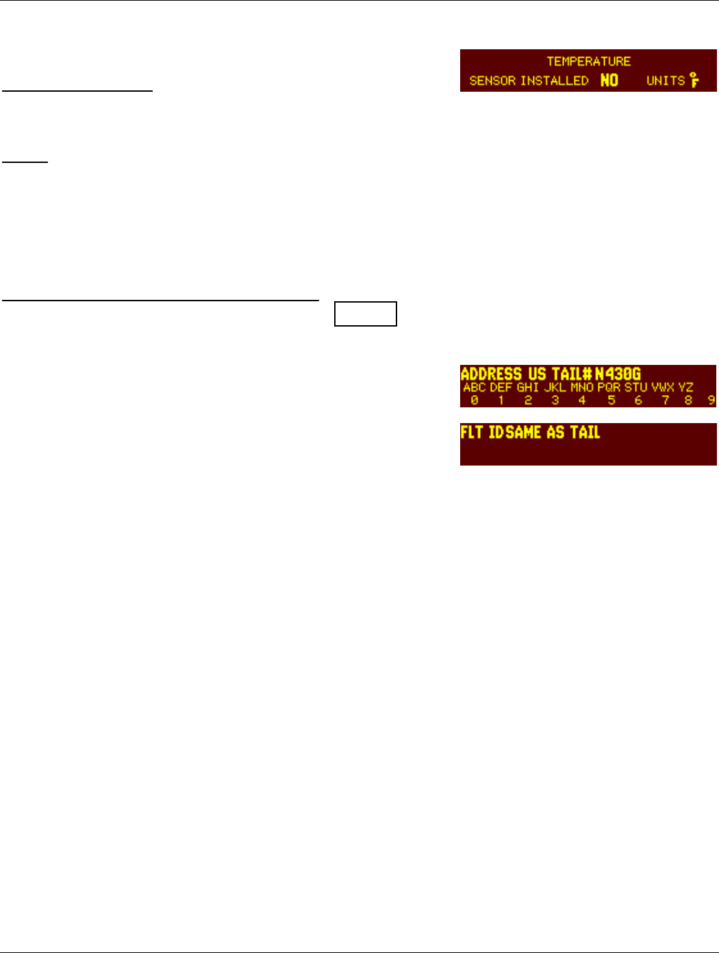
5.2.11 TEMPERATURE PAGE
SENSOR INSTALLED
Sets the Sensor to YES or NO. Default is NO.
UNITS
Sets the units to degrees Fahrenheit or Centigrade. Default is degrees F.
5.2.12 MODE S Address Entry Pages
Aircraft Registration or Flight ID Number Pages
NOTE
It is VERY important to enter the Mode S address correctly in the GTX 330.
During production of a GTX 330 the unit is initially set with an address
of 0. The software recognizes this as an invalid address. When the unit
is powered on for the first time, it will prompt the user to enter a valid
aircraft address. (Addresses can be entered beginning at step 5 below
and ending after step 9 is completed.) Once the aircraft address is
entered, the unit will remain on in the mode that it was turned on.
Or, if the unit is not being turned on for the first time, with the unit powered off:
1. Press and hold the FUNC key while powering on the unit.
2. Power the unit on by pressing the ALT key or turn the unit on with the avionics master switch.
The unit will perform a self-test routine and display a "Jump to Diagnostics" page.
3. Press the FUNC key repeatedly to toggle through the pages until you come to the address
entry page.
a. It will appear either as ADDRESS HEX _ _ _ _ _ _ .
b. Or as ADDRESS US TAIL# N _ _ _ _ _ .
4. If the alternate option is required, press the 8 or 9 key to move to the correct selection.
5. For entering either the address hex code or the US registration number, press the CRSR key 1
time. (This will highlight the address field).
7. Enter the aircraft address using the number keys. Press a key repeatedly to scroll through the
digit and different alpha characters for that key.
8. Press the CRSR key to select the next numeric entry field. Again press a number key as
stated in step 7 and move onto the next field, repeating the process until the complete number
is entered.
9. When finished, press the CRSR key again to accept the number entry.
10. Use the FUNC key to toggle through the rest of the setup pages until it rolls back around to the
aircraft address page.
11. Verify that the address is correct. The unit now contains a Mode S address and may be turned
off.
TEMPERATURE Page
MODE S Address (A/C Reg) Page
MODE S Address (Flight ID) Page
Page 5-12 GTX 330 Installation Manual
Rev. 1 190-00207-02
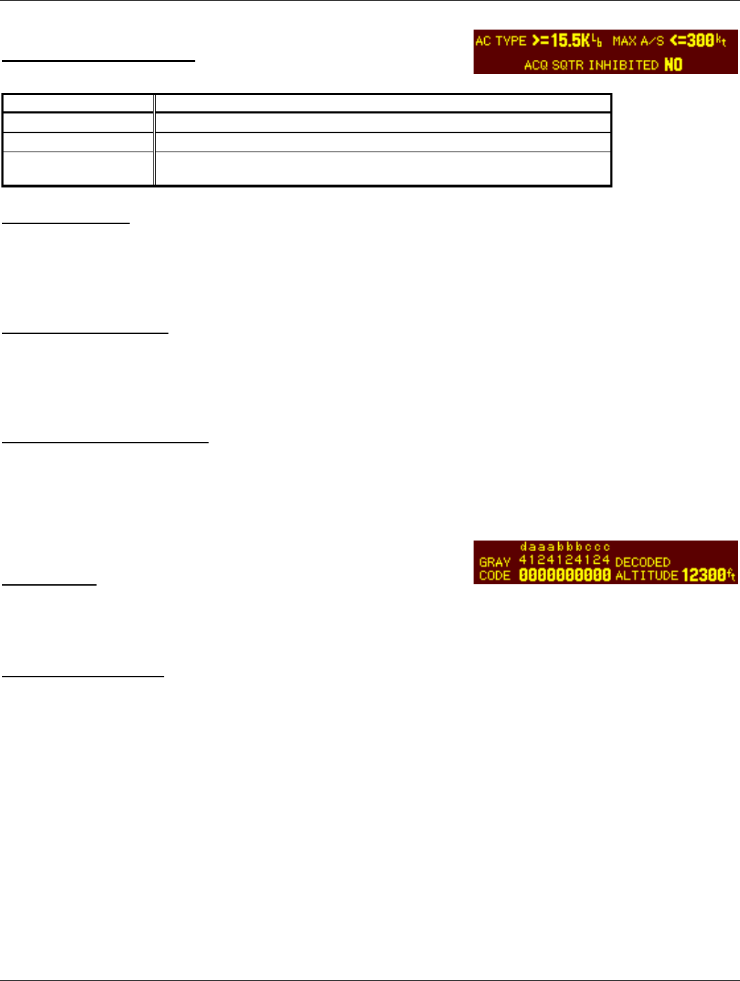
MODE S Aircraft Type Page
Selection Description
AC TYPE ROTOR, >15.5K Lb, <15.5K Lb, or UNKNOWN.
MAX AIRSPEED <75 Kts, <150 Kts, <300 Kts, >300 Kts, or UNKNOWN.
ACQ SQUITTER
INHIBITED
YES OR NO.
AIRCRAFT TYPE
Sets the AIRCRAFT TYPE Message to ROTOR, to a weight of Less Than 15,500 pounds, More Than 15,500
pounds, or Unknown weight. Defaults to Less Than or equal to 15,500 pounds.
MAXIMUM AIRSPEED
Sets the AIRCRAFT AIRSPEED Message to a speed of Less Than or equal to 75 Knots, Less Than or equal to 150
Knots, Less Than or equal to 300 Knots, More Than 300 Knots, or Unknown airspeed. Defaults to Less Than or
equal to 300 Knots.
ACQ SQUITTER INHIBITED
Sets the ACQ SQUITTER INHIBITED to YES or NO. Defaults to NO.
5.2.13 GRAY CODE INPUT Page
GRAY CODE
This field shows the status (1 = ground, 0 = open) of each of the ten gray code altitude inputs. This information may
aid in installation troubleshooting.
DECODED ALTITUDE
This field displays the gray code altitude input in feet. Verify that it is the correct altitude.
MODE S (A/C Type) Page
GRAY CODE INPUT Page
GTX 330 Installation Manual Page 5-13
190-00207-02 Rev. 1
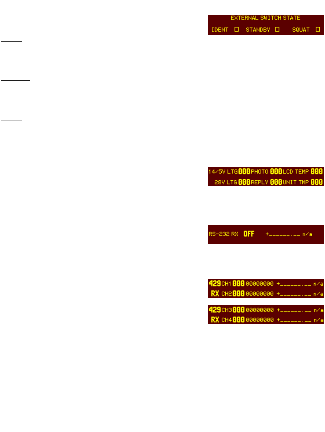
5.2.14 EXTERNAL SWITCH STATE Page
IDENT
This field displays the state of the EXTERNAL IDENT discrete input. The box is filled when EXTERNAL IDENT
is grounded.
STANDBY
This field displays the state of the EXTERNAL STANDBY discrete input. The box is filled when EXTERNAL
STANDBY is grounded.
SQUAT
This field displays the state of the SQUAT SWITCH input. The box is filled when the SQUAT SWITCH input is
active (the aircraft is on the ground as configured on the SETUP 2 page).
5.2.15 ANALOG INPUT Page
5.2.16 RS 232 INPUT Page
5.2.17 429 CHANNNELS Pages
EXTERNAL SWITCH Page
ANALOG INPUT Page
RS 232 INPUT Page
429 CHANNELS 1 and 2
429 CHANNELS 3 and 4

Page 5-14 GTX 330 Installation Manual
Rev. 1 190-00207-02
This page intentionally left blank

GTX 330 Installation Manual Page A1
190-00207-02 Rev. 1
APPENDIX A CERTIFICATION DOCUMENTS
A.1 Continued Airworthiness
Other than for regulatory periodic functional checks, maintenance of the GTX 330 is “on condition” only. Refer to
the GTX 330 Maintenance Manual, (Garmin P/N 190-00207-05). Periodic maintenance of the GTX 330 is not
required.
This section provides assistance to the installing agency in preparing Instructions for Continued Airworthiness (ICA)
in response to Bulletin Number HBAW 98-18, “Checklist for Instructions for Continued Airworthiness for Major
Alterations Approved Under the Field Approval Process”, effective 10/7/98.
Aviation Authority approved installers are hereby granted permission to reference appropriate service instructions
and excerpts from this Installation Manual to accomplish the Instructions for Continued Airworthiness. This
permission does not construe suitability of the documents. It is the applicant’s responsibility to determine the
suitability of the documents for the ICA.
Following is a suggested ICA for a GARMIN GTX 330 unit installation. Some of the checklist items do not apply, in
which case they should be marked “N/A” (Not Applicable).
INSTRUCTIONS FOR CONTINUED AIRWORTHINESS, GARMIN GTX 330
1. Introduction
[Aircraft that has been altered: Registration (N-) number, Make, Model and Serial Number]
Content, Scope,
Purpose and Arrangement: This document identifies the Instructions for Continued Airworthiness for
the modification of the above aircraft by installation of a GARMIN GTX 330.
Applicability: Applies to aircraft altered by installation of the GARMIN GTX 330.
Definitions and Abbreviations: None, N/A.
Precautions: None, N/A.
Units of Measurement: None, N/A.
Referenced Publications: GARMIN GTX 330 Installation Manual, P/N 190-00207-02
GARMIN GTX 330 Maintenance Manual, P/N 190-00207-05
GARMIN STC # [applicable STC number for the specific model installed, refer to Appendix B of this manual].
GARMIN GTX 330 Pilot’s Guide, P/N 190-00207-xx.
Distribution: This document should be a permanent aircraft record.
2. Description of the Alteration
Installation of the GARMIN GTX 330, with interface to Encoding Altimeter or Blind Encoder. Refer to
section 4 and figures 4-1 and 4-2 of this manual for interconnect information. Antenna installation, removal
and replacement should be in accordance with applicable provisions of AC43.13-1B and 43.13-2A.
3. Control, Operation Information
Refer to the GTX 330 Pilot’s Guide.
4. Servicing Information
N/A

Page A2 GTX 330 Installation Manual
Rev. 1 190-00207-02
5. Maintenance Instructions
Maintenance of the GTX 330 is ‘on condition’ only. Periodic maintenance is not required. Refer to the
GTX 330 Maintenance Manual.
6. Troubleshooting Information
Refer to the GTX 330 Maintenance Manual.
7. Removal and Replacement Information
Refer to section 2 of this manual. If the unit is removed and reinstalled, a functional check of the equipment
should be conducted in accordance with section 5 of this manual.
8. Diagrams
Refer to section 3 and section 4 of this manual.
9. Special Inspection Requirements
N/A
10. Application of Protective Treatments
N/A
11. Data: Relative to Structural Fasteners
Antenna installation, removal and replacement should be in accordance with applicable provisions of
AC43.13-1A and 43.13-2A. Also, refer to section 2 of this manual.
12. Special Tools
N/A
13. This Section is for Commuter Category Aircraft Only
A. Electrical loads: Refer to section 1.3 of this manual.
B. Methods of balancing flight controls: N/A.
C. Identification of primary and secondary structures: N/A.
D. Special repair methods applicable to the airplane: Antenna installation, removal, and replacement should be
in accordance with applicable provisions of AC43.13-1B and 43.13-2A.
14. Overhaul Period
No additional overhaul time limitations.
15. Airworthiness Limitation Section
N/A.
16. Revision
To revise this ICA, a letter must be submitted to the local FSDO with a copy of the revised FAA Form 337, and
revised ICA. The FAA inspector accepts the change by signing Block 3 and including the following statement:
“The attached revised/new Instructions for Continued Airworthiness (date ______) for the above aircraft or
component major alteration have been accepted by the FAA, superseding the Instructions for Continued
Airworthiness (date ______).”
17. Assistance
Flight Standards Inspectors have the resources to respond to questions regarding the ICA.

GTX 330 Installation Manual Page A3
190-00207-02 Rev. 1
Implementation and Record Keeping
For major alterations performed in accordance with FAA field approval policy, the owner/operator operating under
Part 91 is responsible for ensuring that the ICA is made part of the applicable section 91.409 inspection program for
their aircraft. This is accomplished when a maintenance entry is made in the aircraft’s maintenance record in
accordance with section 43.9. This entry records the major alteration and identifies the original ICA location (e.g.,
Block 8 of FAA Form 337, dated ______) along with a statement that the ICA is now part of the aircraft’s
inspection/maintenance requirements.

Page A4 GTX 330 Installation Manual
Rev. 1 190-00207-02
A.2 ENVIRONMENTAL QUALIFICATION FORM
NOMENCLATURE: GTX 330 Airborne ATC/Mode S Transponder Equipment
TYPE/MODEL/PART NO.: 010-00230–( ), which includes 011-00455–( )
TSO/JTSO COMPLIANCE: TSO – C112 Class 2A, and TSO - C74c Class 1A
MANUFACTURER'S SPECIFICATION AND/OR OTHER
APPLICABLE SPECIFICATION: 004-00099-00 Minimum Performance Specification
MANUFACTURER: GARMIN INTERNATIONAL
ADDRESS: 1200 E 151st St, Olathe, Kansas 66062
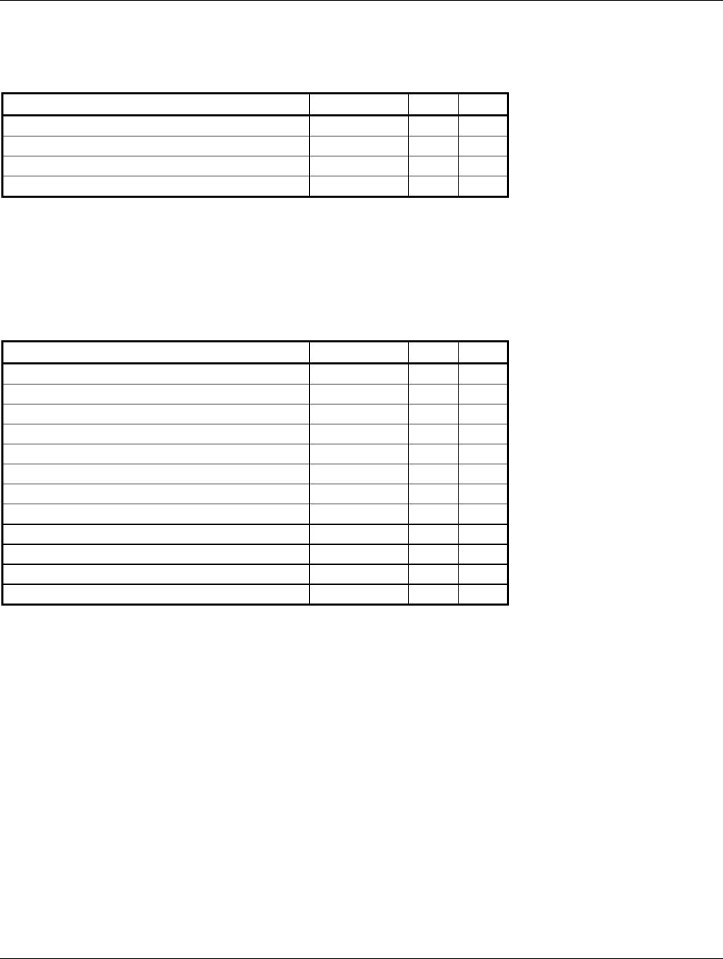
Conditions RTCA DO-160D
Section
Description of Conducted Tests
Temperature and Altitude 4.0 Equipment tested to Categories A2 B2 F1
Low Temperature 4.5.1 -45 degrees C
High Temperature 4.5.2. & 4.5.3 +70 degrees C
In-Flight Loss of Cooling 4.5.4 Cooling air not required but highly recommended
Altitude 4.6.1 55,000 Feet
Decompression 4.6.2
Overpressure 4.6.3
Temperature Variation 5.0 Equipment tested to Category B
Humidity 6.0 Equipment tested to Category A
Shock 7.0 Equipment tested to Category B
Vibration 8.0 Equipment tested in each aircraft type to aircraft zone 2.
Aircraft Type 2 and 6 were tested to Category S2,
Vibration level B2. Aircraft Type 3, 4, and 5 were tested
to Category S, Vibration level M.
Note: DO-160D vibration level M modified to increase
level to RTCA DO-160C Curve N for Helicopters as
follows-0.1 inches peak-to-peak double amplitude from
5 Hz to 17 Hz, 1.5g-Pk from 17 Hz to 500 Hz.

GTX 330 Installation Manual Page A5
190-00207-02 Rev. 1
Conditions Section Description of Conducted Tests
Explosion 9.0 Equipment identified as Category X, no test required
Waterproofness 10.0 Equipment identified as Category X, no test required
Fluids Susceptibility 11.0 Equipment identified as Category X, no test required
Sand and Dust 12.0 Equipment identified as Category X, no test required
Fungus 13.0 Equipment identified as Category X, no test required
Salt Spray 14.0 Equipment identified as Category X, no test required
Magnetic Effect 15.0 Equipment tested to Class Z
Power Input 16.0 Equipment tested to Category BZ
Voltage Spike 17.0 Equipment tested to Category A
Audio Frequency Conducted
Susceptibility
18.0 Equipment tested to Category Z
Induced Signal Susceptibility 19.0 Equipment tested to Category Z
Radio Frequency
Susceptibility
20.0 Equipment tested for conducted susceptibility to Category
T, radiated susceptibility to Category T, and pulse test to
Category T.
Radio Frequency Emission 21.0 Equipment tested to Category B, Equipment tested to
Category M up to 2 GHz.
Lightning Induced Transient
Susceptibility
22.0 Equipment identified as Category A3E3
Lightning Direct Effects 23.0 Equipment identified as Category X, no test required
Icing 24.0 Equipment identified as Category X, no test required
Electrostatic Discharge (ESD) 25.0 Equipment identified as Category X, no test required

GTX 330 Installation Manual Page B1
190-00207-02 Rev. 1
APPENDIX B
STC PERMISSION
Consistent with N8110.69 or Order 8110.4, Aviation Authority approved installers are hereby granted permission to
use STC #(xxxxxxxxx) data to modify aircraft.

Page B2 GTX 330 Installation Manual
Rev. 1 190-00207-02
To be supplied