Garmin 0060200 AIRCRAFT MOUNTED WEATHER RADAR TRANSMITTER User Manual Cover Rev1
Garmin International Inc AIRCRAFT MOUNTED WEATHER RADAR TRANSMITTER Cover Rev1
Garmin >
Contents
- 1. PILOT MANUAL
- 2. INSTALLATION MANUAL
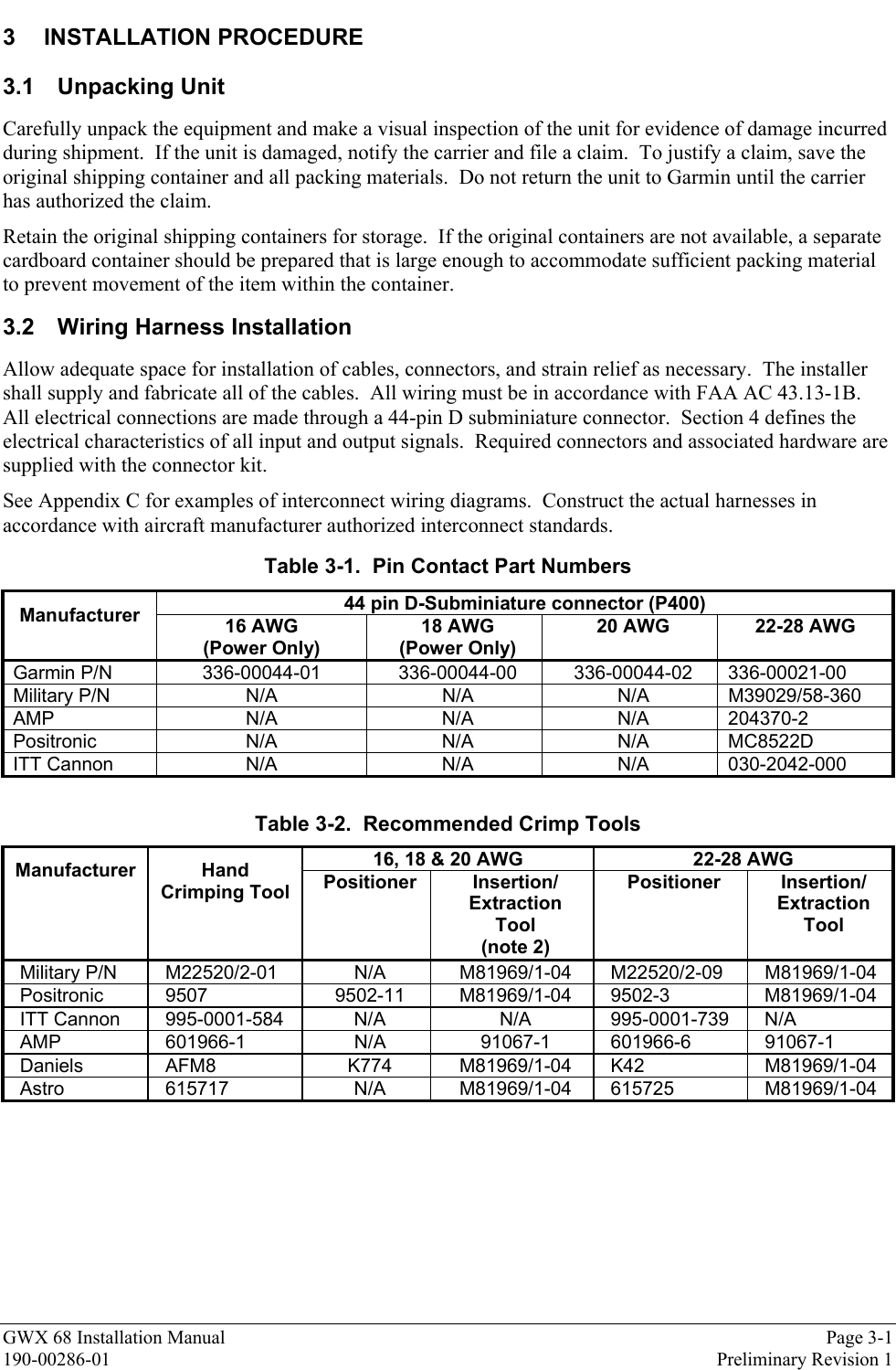
INSTALLATION MANUAL
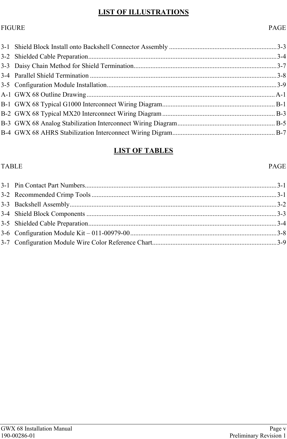
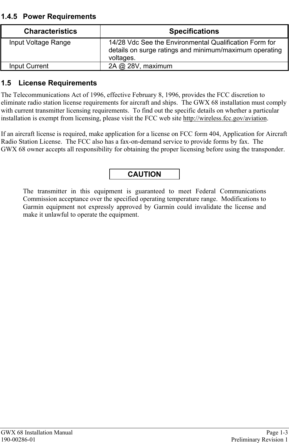
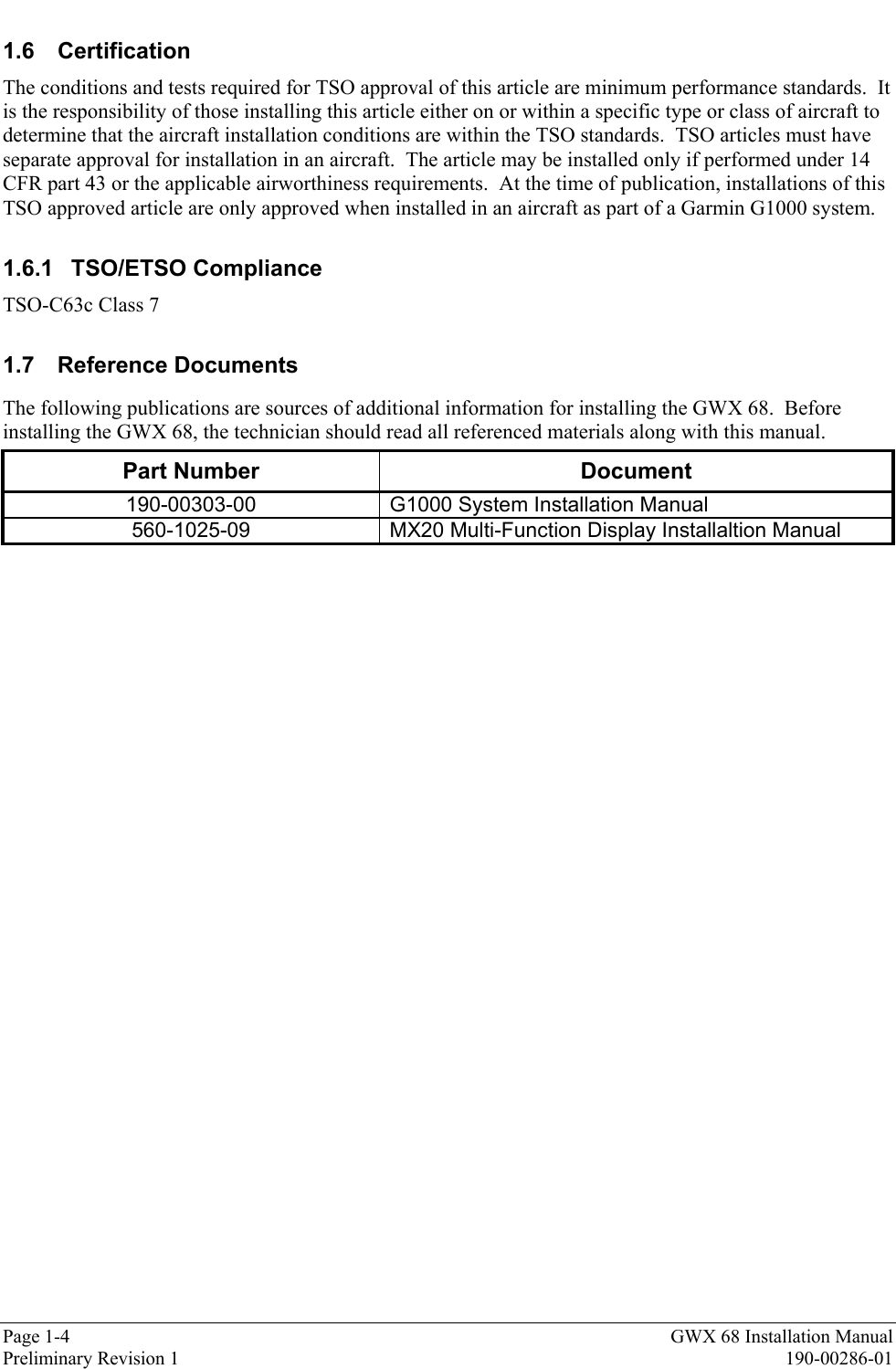

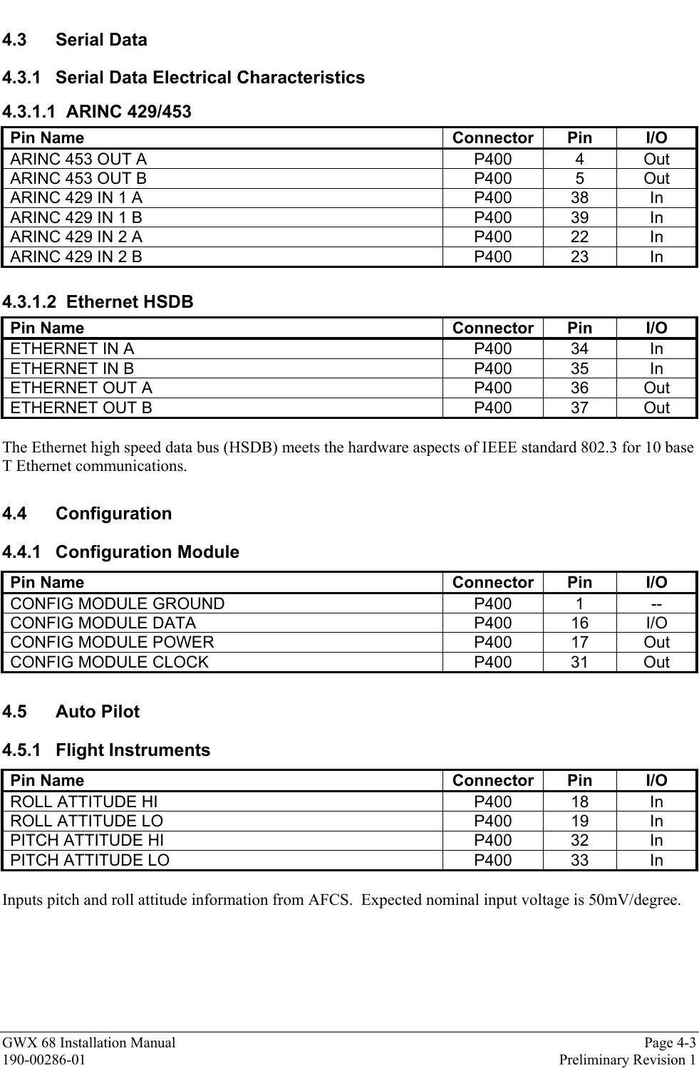
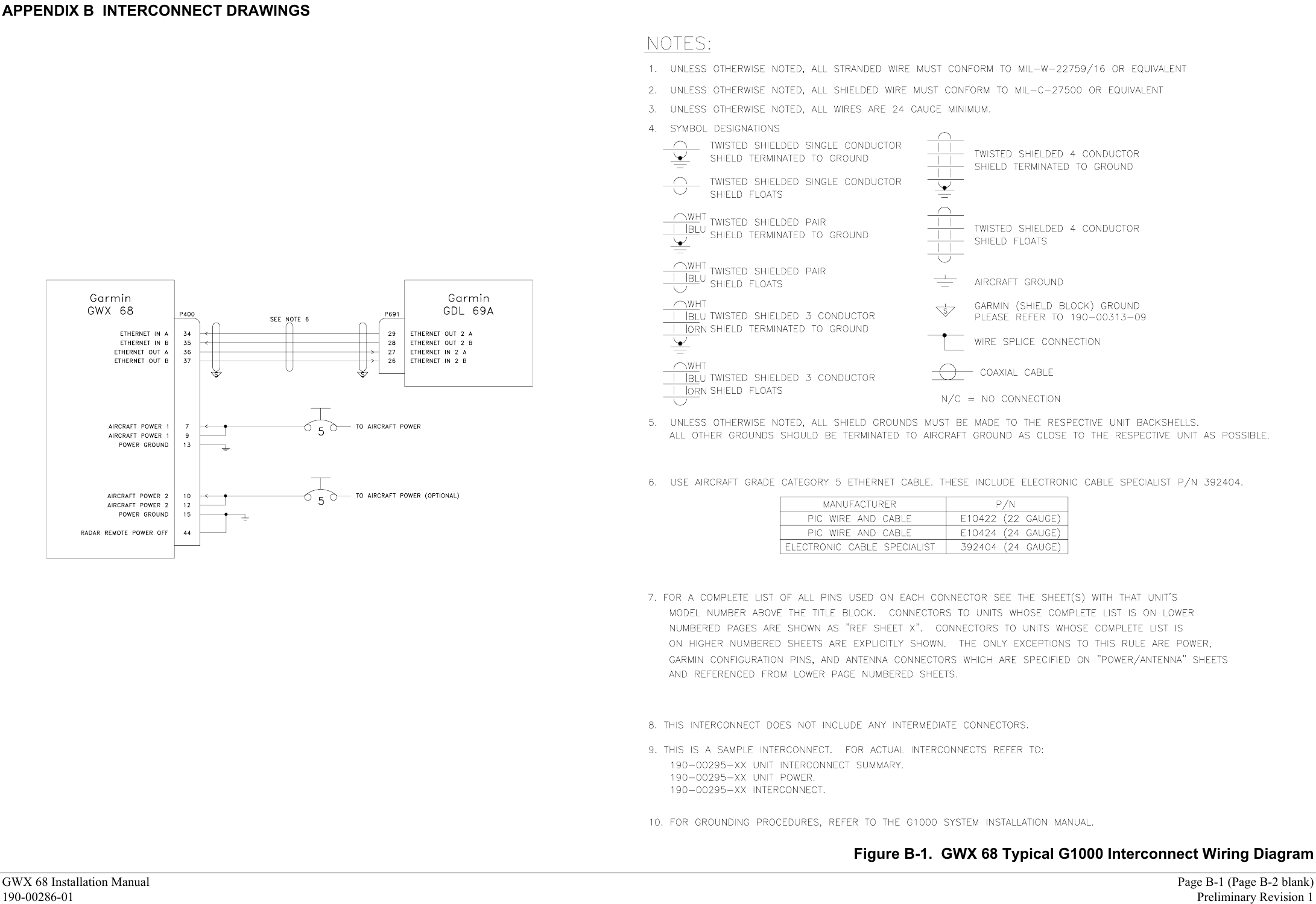
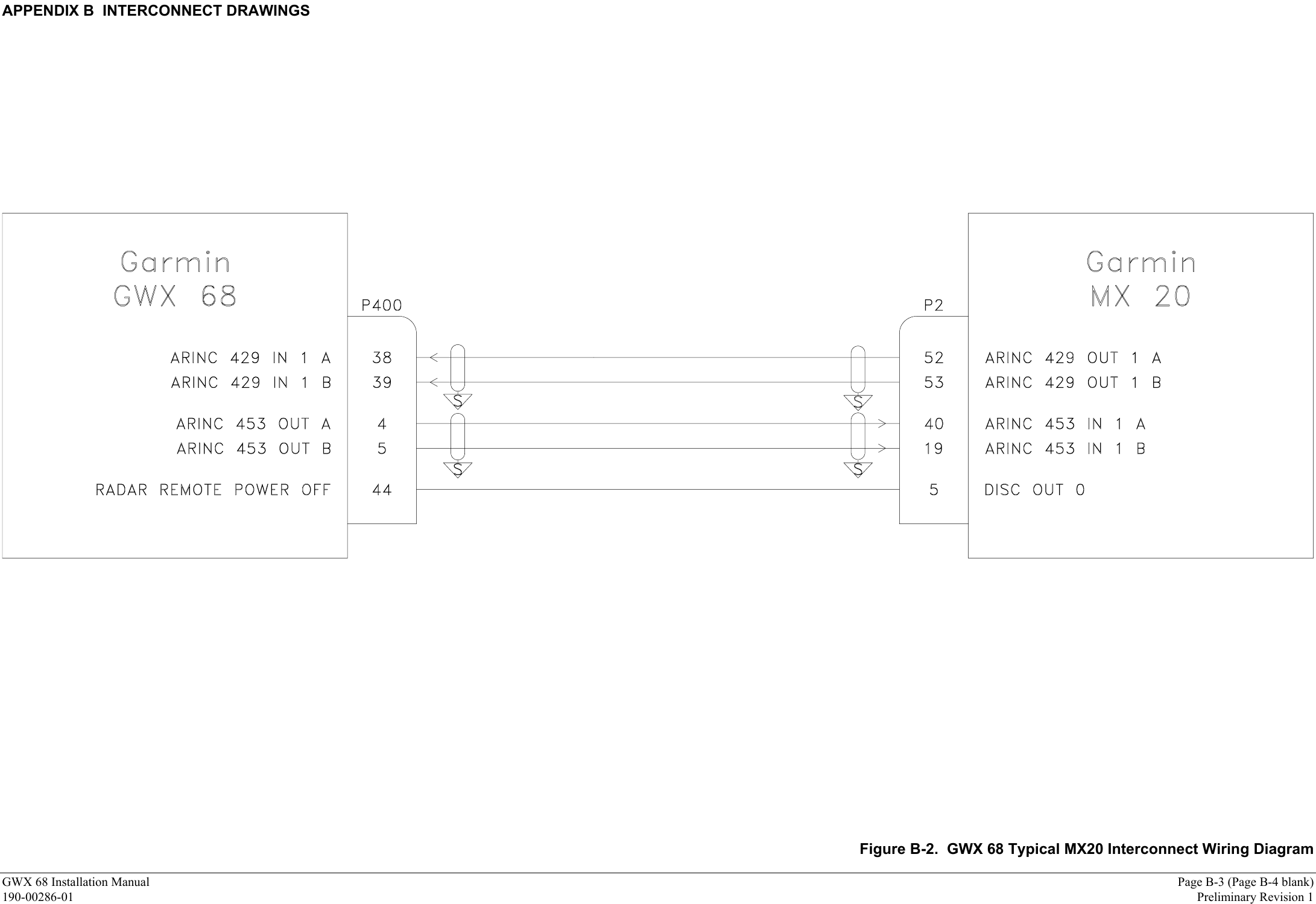
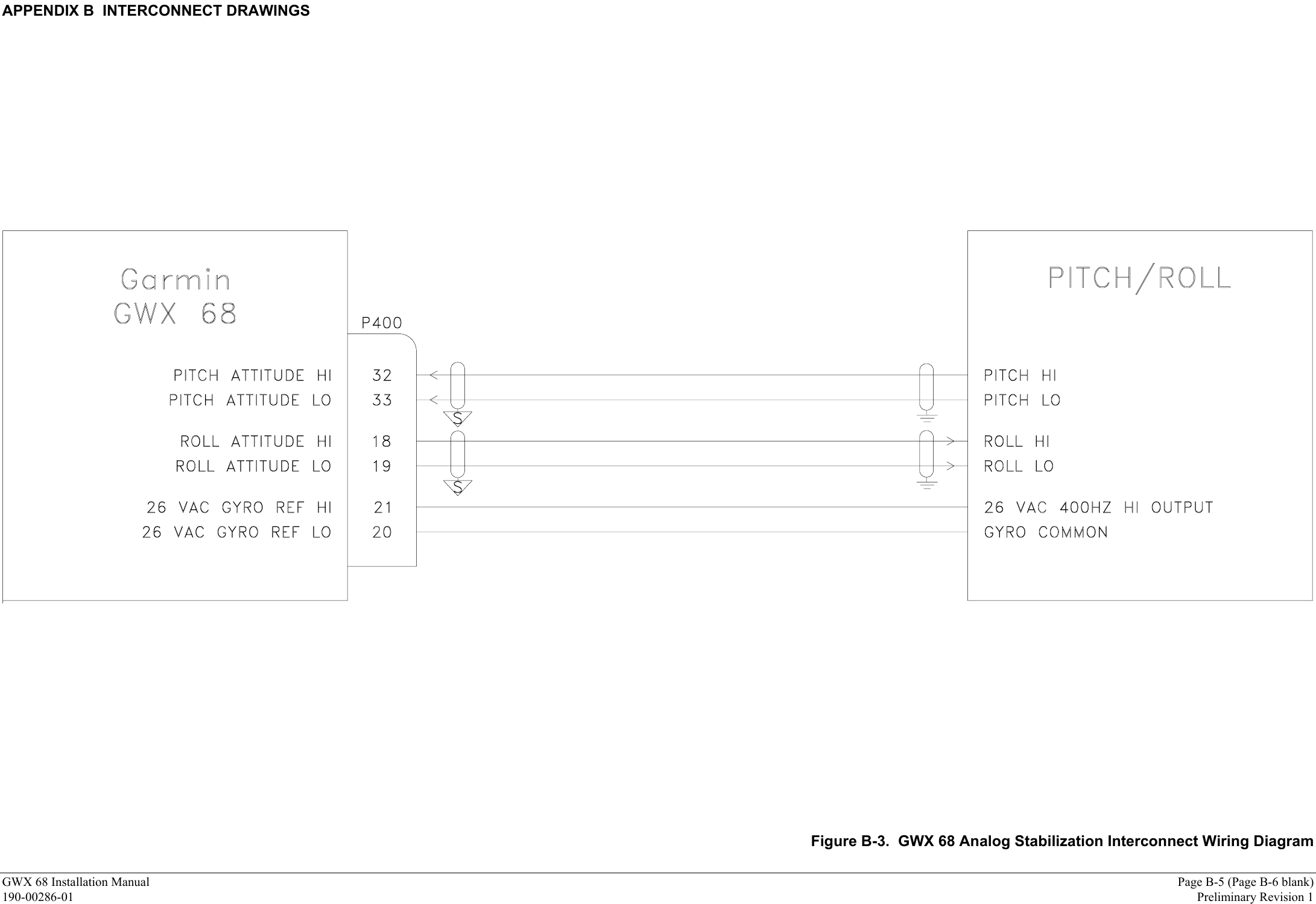
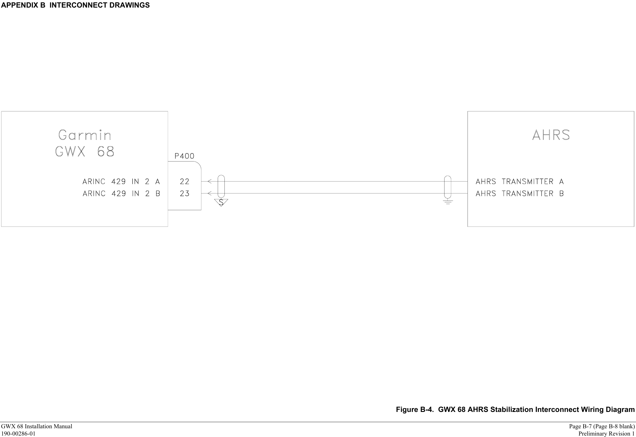
![APPENDIX A OUTLINE & INSTALLATION DRAWINGSGWX 68 Installation Manual Page A-1 (Page A-2 blank)190-00286-01 Preliminary Revision 14.600±.022 116.84±0.56AZIMUTH AXIS6.815±.064 173.09±1.6345°MAX. AZIMUTHANGLEBULKHEAD MOUNTINGSURFACE6.624 168.253.312 84.126.750 171.453.375 85.7310.00 254.04X .265 THRU6.73.25 6.4.30 7.64.951±.029 125.75±0.74TILT AXIS2.47 62.730°MAX. TILTANGLER5.530 140.46MAX SPHERICAL RADIUS10" ANTENNAR6.548 166.32MAX SPHERICAL RADIUS12" ANTENNANOTES:1. DIMENSIONS: INCHES[mm]2. 12" ANTENNA SHOWNUPPRELIMINARY4X 211-64214-221/4-28 SOCKET HEAD CAP SCREWSRIGHT ANGLE CONNECTORFigure A-1. GWX 68 Outline Drawing](https://usermanual.wiki/Garmin/0060200.INSTALLATION-MANUAL/User-Guide-546560-Page-32.png)