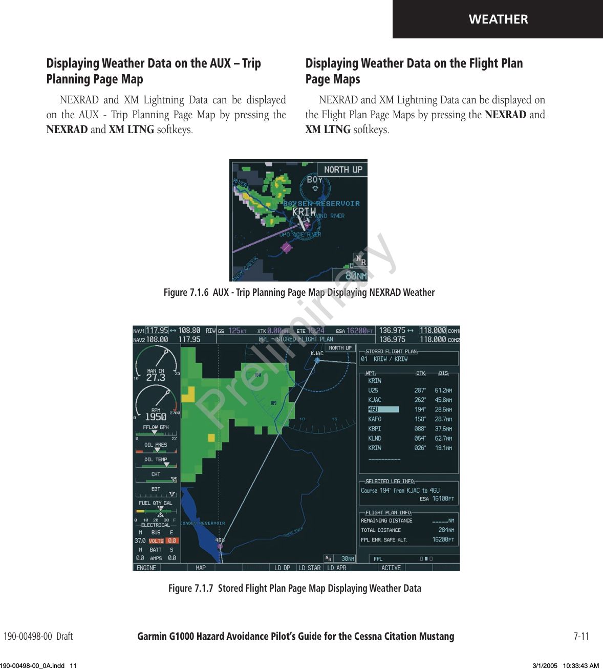
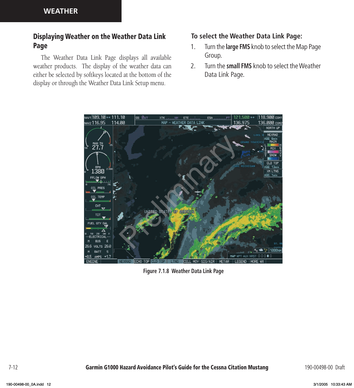
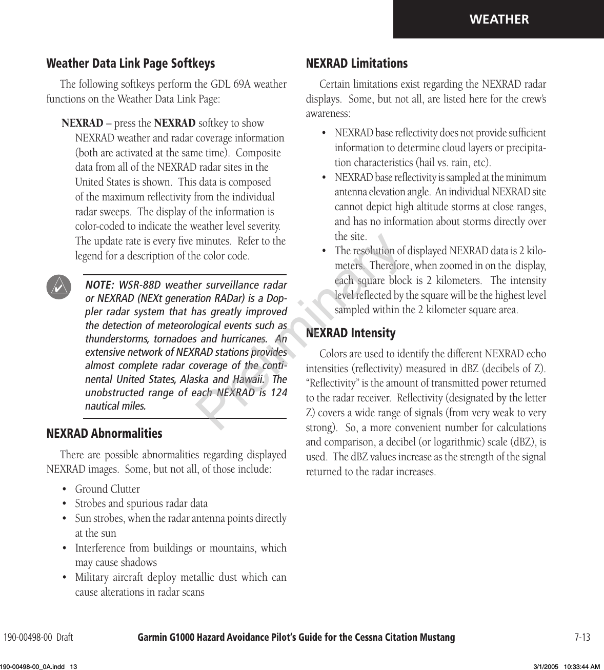
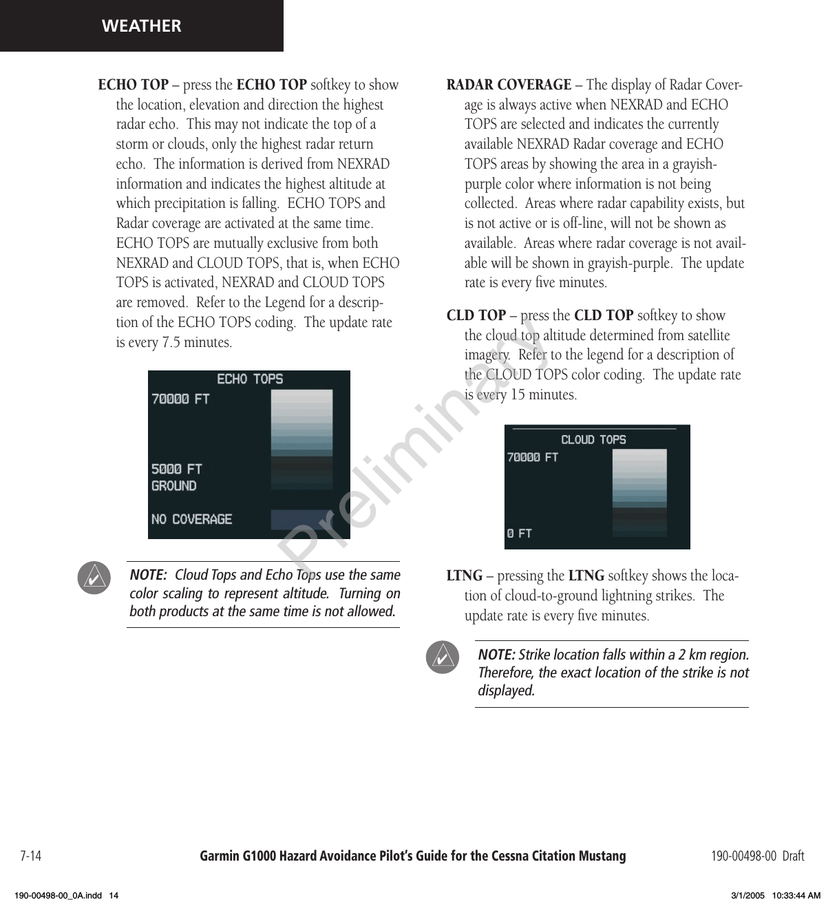
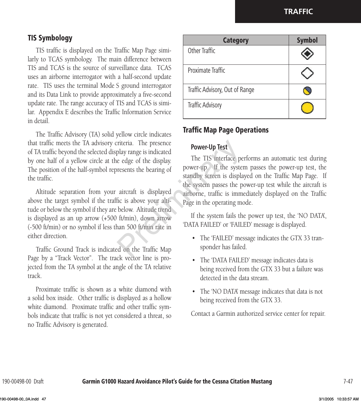
Garmin 0060200 AIRCRAFT MOUNTED WEATHER RADAR TRANSMITTER User Manual 190 00498 00 0A indd
Garmin International Inc AIRCRAFT MOUNTED WEATHER RADAR TRANSMITTER 190 00498 00 0A indd
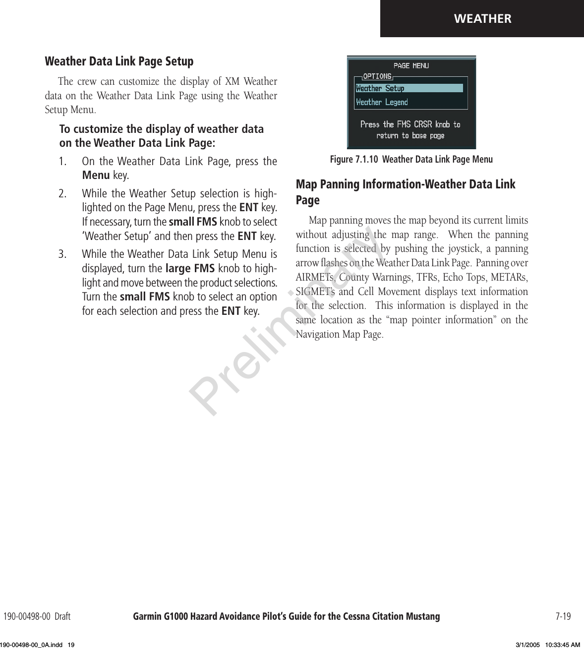
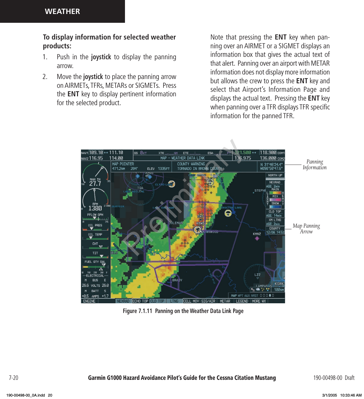
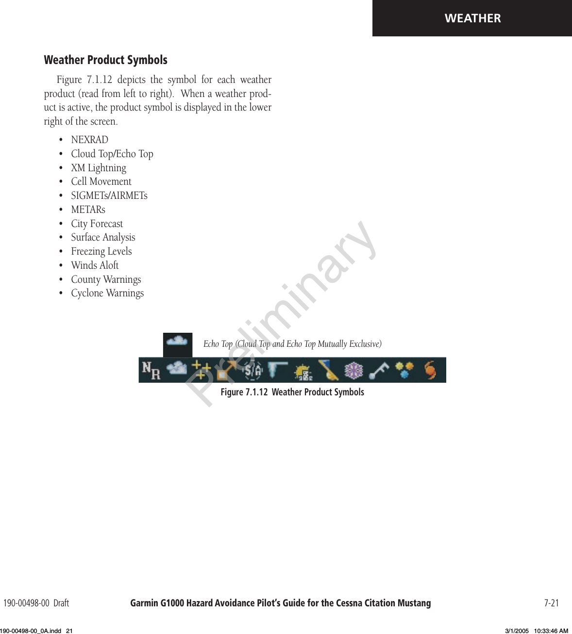
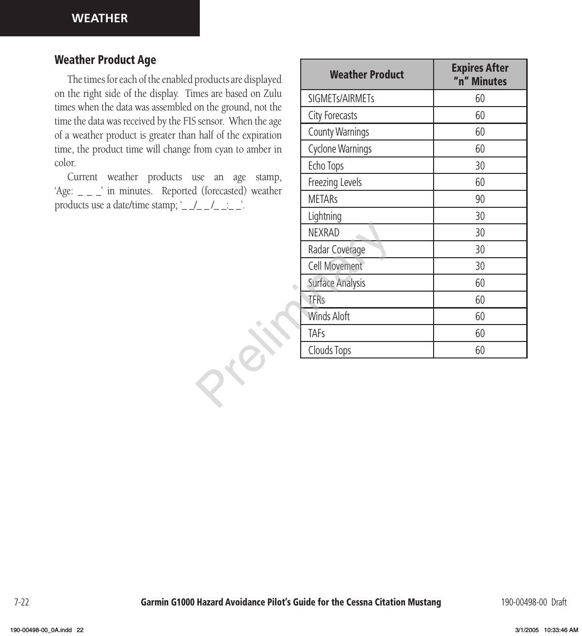
Garmin >
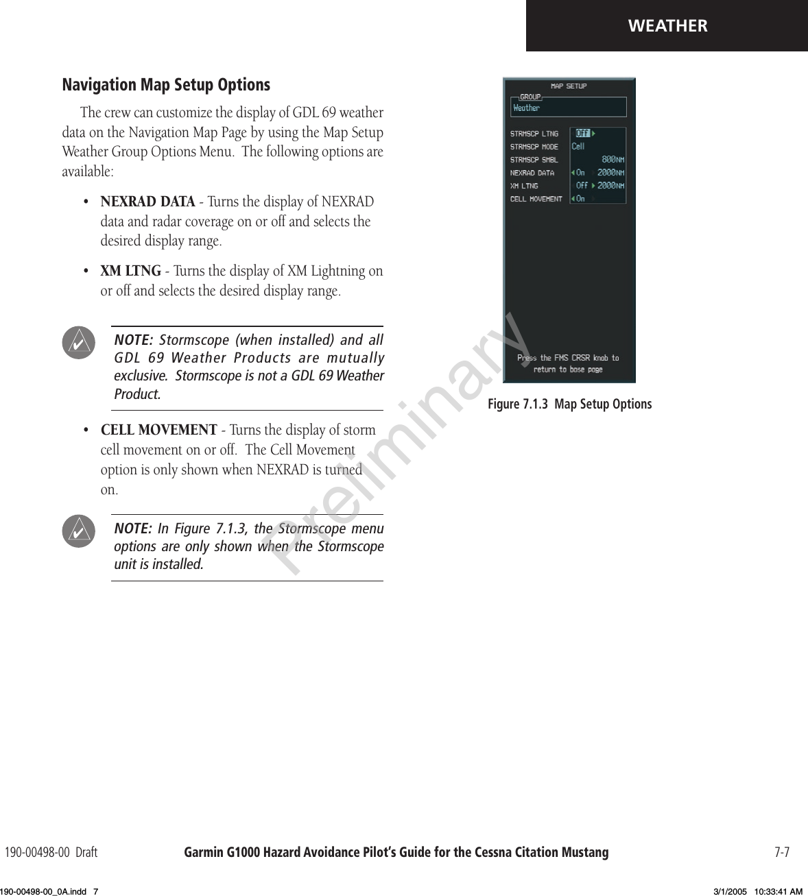
Contents
- 1. PILOT MANUAL
- 2. INSTALLATION MANUAL
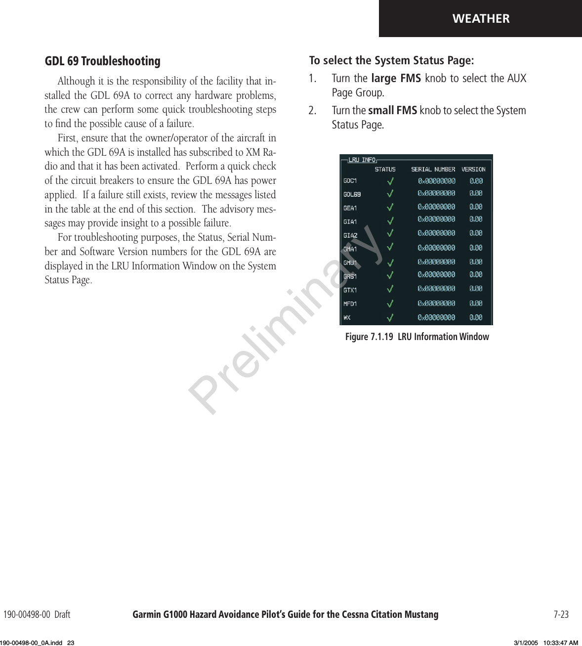
PILOT MANUAL