Garmin 0060200 AIRCRAFT MOUNTED WEATHER RADAR TRANSMITTER User Manual 190 00498 00 0A indd
Garmin International Inc AIRCRAFT MOUNTED WEATHER RADAR TRANSMITTER 190 00498 00 0A indd
Garmin >
Contents
- 1. PILOT MANUAL
- 2. INSTALLATION MANUAL
PILOT MANUAL

G1000
TM
hazard avoidance pilot’s guide
for the Cessna Citation Mustang
Preliminary
190-00498-00_0A.indd 1 3/1/2005 10:33:38 AM
Garmin G1000 Hazard Avoidance Pilot’s Guide for the Cessna Citation Mustang 190-00498-00 Draft
Record of Revisions
Revision Date of Revision Revision Page Range Description
Draft 03/01/05 7-1 – 7-53 Initial release.
Preliminary
190-00498-00_0A.indd 2 3/1/2005 10:33:38 AM

Garmin G1000 Hazard Avoidance Pilot’s Guide for the Cessna Citation Mustang190-00498-00 Draft 7-1
WEATHER
This document describes the Hazard Avoidance features
of the G1000 system. The main hazards to flight safety are
flying in or near weather, flying in close proximity to the
terrain and other flight traffic in close proximity.
The information contained in this section assumes un-
derstanding of the G1000 Multi Function Display.
This section is divided into groups as follows:
Weather
• GDL 69A (XM Weather)
• GWX 68
• WX 500 Stormscope
TAWS/Terrain
• Terrain Proximity
• TAWS (Terrain Awareness Warning System)
Traffic
• TIS (Traffic Information System)
• TAS (Traffic Advisory System)
7.1 WEATHER
CAUTION: GDL 69A NEXRAD weather data is to
be used for long-range planning purposes only.
Due to inherent delays and relative age of the
data that can be received, NEXRAD weather data
should not be used for short-range avoidance of
weather.
WARNING: Use of any GDL 69A Weather Product
for thunderstorm penetration is prohibited.
Weather information provided by the GDL 69
is approved only for weather avoidance, not
penetration.
Preliminary
190-00498-00_0A.indd 1 3/1/2005 10:33:39 AM

Garmin G1000 Hazard Avoidance Pilot’s Guide for the Cessna Citation Mustang 190-00498-00 Draft
7-2
WEATHER
GDL 69A WEATHER AND DIGITAL
AUDIO ENTERTAINMENT
The GDL 69A is a remote sensor that is capable of re-
ceiving XM Weather and displaying it on the G1000 Multi
Function Display and the Primary Flight Display Inset
Map. The GDL 69A is also capable of receiving XM Radio
Services. XM Weather and XM Radio operate in the S-
band frequency range to provide continuous uplink capa-
bilities at any altitude throughout North America.
NOTE: Before the GDL 69A can be used, the unit
must be activated by XM Satellite Radio. The XM
Satellite Radio Activation Instruction Sheet con-
tains important information required to initiate
XM Satellite Radio Subscription for the GDL 69A.
This sheet was given to the aircraft owner at the
time of delivery.
NOTE: Refer to the G1000 Option pilot’s guide
for information on the XM entertainment radio
segment of the GDL 69A.
Radio IDs
The GDL 69A are shipped with a Data Radio ID and an
Audio Radio ID. You must obtain the Radio IDs of your
receiver(s) before subscribing to XM services. The IDs are
attached to the XM Satellite Radio Activation Instructions
sheet included with the unit. They are also printed on a
label on the back of the unit and are displayed on the XM
Information Page. Contact the installer if you are unable
to locate the Radio IDs.
Activating XM Radio Services
To activate the XM Radio Weather Service:
1. Turn the large FMS knob to select the Auxiliary
Page Group. Turn the small FMS knob to
display the AUX - XM Page.
2. Press the INFO softkey to display the XM
Information Page.
3. Contact XM Satellite Radio through the Internet
or by telephone. Follow the directions provided
by XM Satellite Radio.
4. Verify that the desired services are activated
and press the DONE softkey.
5. Turn the large FMS knob to highlight ‘YES’
or ‘NO.’ Press the ENT key to complete
activation.
Preliminary
190-00498-00_0A.indd 2 3/1/2005 10:33:39 AM
Garmin G1000 Hazard Avoidance Pilot’s Guide for the Cessna Citation Mustang190-00498-00 Draft 7-3
WEATHER
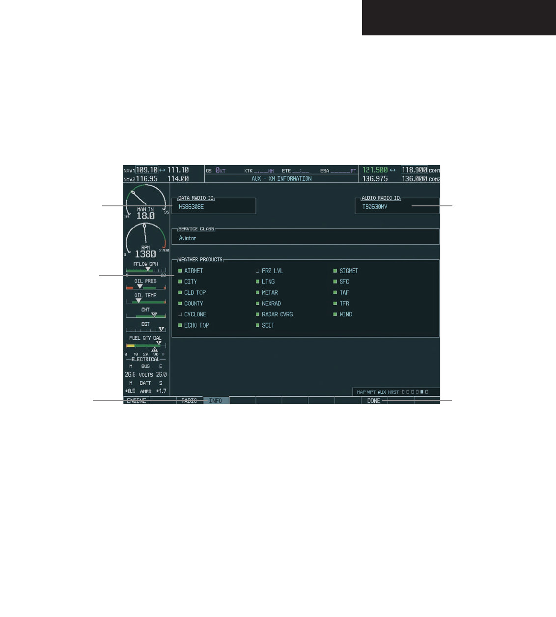
Figure 7.1.1 XM Information Page
Audio
Radio ID
DONE
Softkey
Weather
Products
Data
Radio ID
INFO
Softkey
Preliminary
190-00498-00_0A.indd 3 3/1/2005 10:33:39 AM

Garmin G1000 Hazard Avoidance Pilot’s Guide for the Cessna Citation Mustang 190-00498-00 Draft
7-4
WEATHER
GDL 69 WEATHER
Flight Information Services (FIS) weather information
provided by the GDL 69 is displayed on the following
MFD Maps and Pages:
• Navigation Map Page (NEXRAD and XM Light-
ning only)
• Weather Data Link Page (complete GDL 69 capa-
bility)
• Nearest Pages (NEXRAD and XM Lightning only)
• Airport Information Page (NEXRAD and XM
Lightning only)
• Flight Planning Maps (NEXRAD and XM Light-
ning only)
• AUX - Trip Planning Map (NEXRAD and XM
Lightning only)
• WPT - Weather Information Page - part of the
WPT - Airport Information Page (METAR and
TAF information only)
FIS weather information is also displayed on the Pri-
mary Flight Display Inset Map. See the G1000 PFD Pilot’s
Guide for more information.
NOTE: Temporary Flight Restrictions (TFRs) are
displayed on all pages. Cell Movement is always
displayed with NEXRAD data.
Complete GDL 69 capabilities include:
• Graphical NEXRAD Data (NEXRAD)
• Graphical METAR Data (METAR)
• Textual METAR Data
• Textual Terminal Aerodrome Forecasts (TAF)
• City Forecast Data
• Graphical Wind Data (WIND)
• Graphical Echo Tops (ECHO TOP)
• Graphical Cloud Tops (CLD TOP)
• Graphical Lightning Strikes (XM LTNG)
• Graphical Storm Cell Movement (CELL MOV)
• NEXRAD Radar Coverage (displayed with
NEXRAD data)
• SIGMETs/AIRMETs (SIG/AIR)
• Surface Analysis including City Forecasts (SFC)
• County Warnings (COUNTY)
• Freezing Levels (FRZ LVL)
• Hurricane Track (CYCLONE)
• Temporary Flight Restrictions (TFR)
NOTE: FIS (also known as Flight Information
Services - Broadcast, or FIS-B) supplies real-time
weather information and other flight advisory
information for enhanced situational awareness,
24 hours a day, 7 days a week.
Preliminary
190-00498-00_0A.indd 4 3/1/2005 10:33:40 AM

Garmin G1000 Hazard Avoidance Pilot’s Guide for the Cessna Citation Mustang190-00498-00 Draft 7-5
WEATHER
Displaying Weather Data on the Navigation
Map Page
When appropriately configured, the Navigation Map
Page displays NEXRAD, Cell Movement, TFRs and XM
Lightning data. This capability improves situational
awareness, which makes it easier to relate storm activity to
airports, navaids, obstacles and other ground references.
Navigation Map Page Weather Control
Softkeys
The following softkeys control the display of GDL 69
weather data on the Navigation Map Page:
NEXRAD – pressing the NEXRAD softkey displays
NEXRAD weather and coverage information. The
NEXRAD option is mutually exclusive with the
TOPO, TERRAIN and STORMSCOPE options.
That is, when NEXRAD is activated, TOPO and/or
TERRAIN and/or STORMSCOPE are turned off.
XM LTNG – pressing the XM LTNG softkey displays
XM lightning information. XM Lightning is mutu-
ally exclusive with the STORMSCOPE option.
To display weather data on the Navigation
Map Page:
1. Press the
MAP
softkey.
2. Press the
NEXRAD or XM LTNG
softkey to dis-
play the desired weather. Press the applicable
softkey again to remove weather data from the
Navigation Map Page.
Preliminary
190-00498-00_0A.indd 5 3/1/2005 10:33:40 AM
Garmin G1000 Hazard Avoidance Pilot’s Guide for the Cessna Citation Mustang 190-00498-00 Draft
7-6
WEATHER
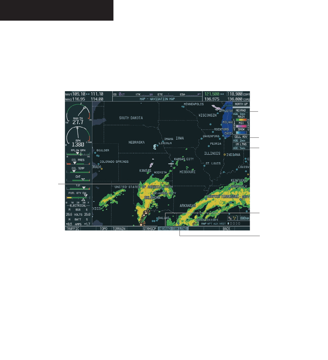
Cell Movement
Status
XM Lightning
Status
XM Lightning
Softkey
Figure 7.1.2 Navigation Map Page Displaying NEXRAD Weather
NEXRAD Softkey
NEXRAD
Weather
NEXRAD
Storms/Legend
Preliminary
190-00498-00_0A.indd 6 3/1/2005 10:33:40 AM
Garmin G1000 Hazard Avoidance Pilot’s Guide for the Cessna Citation Mustang190-00498-00 Draft 7-7
WEATHER
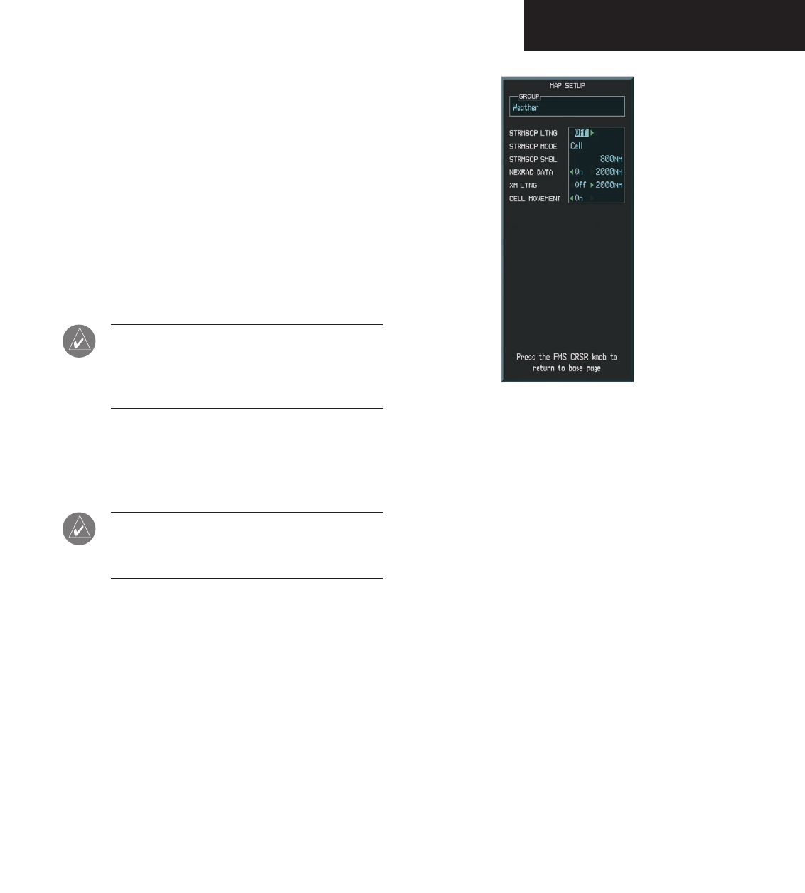
Navigation Map Setup Options
The crew can customize the display of GDL 69 weather
data on the Navigation Map Page by using the Map Setup
Weather Group Options Menu. The following options are
available:
• NEXRAD DATA - Turns the display of NEXRAD
data and radar coverage on or off and selects the
desired display range.
• XM LTNG - Turns the display of XM Lightning on
or off and selects the desired display range.
NOTE: Stormscope (when installed) and all
GDL 69 Weather Products are mutually
exclusive. Stormscope is not a GDL 69 Weather
Product.
• CELL MOVEMENT - Turns the display of storm
cell movement on or off. The Cell Movement
option is only shown when NEXRAD is turned
on.
NOTE: In Figure 7.1.3, the Stormscope menu
options are only shown when the Stormscope
unit is installed.
Figure 7.1.3 Map Setup Options
Preliminary
190-00498-00_0A.indd 7 3/1/2005 10:33:41 AM
Garmin G1000 Hazard Avoidance Pilot’s Guide for the Cessna Citation Mustang 190-00498-00 Draft
7-8
WEATHER
To customize the Navigation Map Page:
1. On the Navigation Map page, press the Menu
key.
2. While the ‘Map Setup’ selection is highlighted
on the Page Menu, press the ENT key.
3. Turn the small FMS knob to display the group
selection window. Turn the FMS knob to select
the ‘Weather Group’ and press the ENT key.
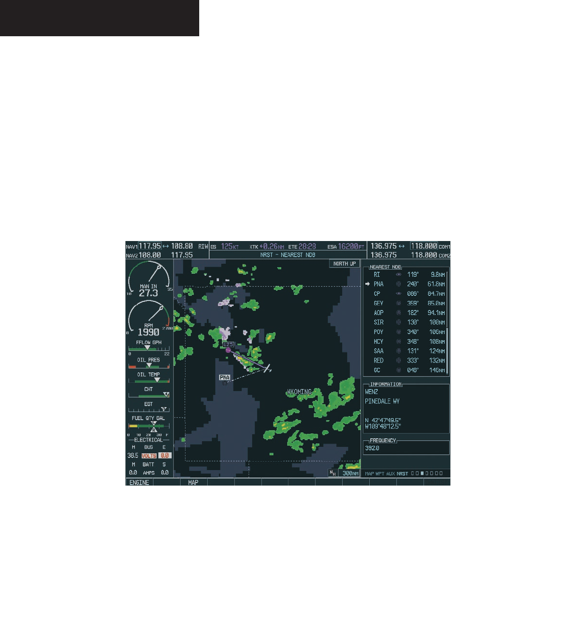
Figure 7.1.4 Weather Display on the Nearest NDB Page
4. While the Map Setup menu is displayed, turn
the large FMS knob to highlight and move
between the product selections. When an item
is highlighted, turn the small FMS knob to
select the desired option and press the ENT
key.
Displaying Weather Data on the Nearest Pages
In addition to the Navigation Map Page, the Nearest
Pages displays Stormscope, NEXRAD and XM Lightning
data.
Preliminary
190-00498-00_0A.indd 8 3/1/2005 10:33:41 AM

Garmin G1000 Hazard Avoidance Pilot’s Guide for the Cessna Citation Mustang190-00498-00 Draft 7-9
WEATHER
Displaying METAR and TAF on the Airport
Information Page
METAR and TAF text is displayed on the Airport In-
formation Page when the WX softkey is pressed. Once
the WX softkey is pressed the page title changes from
‘WPT - Airport Information’ to ‘WPT - Weather Infor-
mation’. The METAR data is first displayed in a decoded
fashion, then the raw text is displayed. TAF information
is only displayed in its raw form.
NOTE: METAR is the Aviation Routine Weather
Report, generally standard around the world.
Temperatures are given in Celsius. The atmo-
spheric pressure is reported in hecto pascals
everywhere but the US where it is reported in
inches of mercury. Standard temperature and
atmospheric pressure are 59° F (15°C) and 29.92
in. Hg (1013.2 hPa).
`
NOTE: TAF is an airport forecast, generally stan-
dard around the world. TAF forecasts significant
weather changes, temporary changes, probable
changes and expected changes in weather condi-
tions.
To display METAR and TAF text on the Air-
port Information Page:
1. Turn the
large FMS
knob to select the WPT Page
Group.
2. Turn the
small FMS
knob to select the Airport
Information Page.
3. Press the WX softkey to display METAR and TAF
text (METAR and TAF information is updated
every 12 minutes).
Preliminary
190-00498-00_0A.indd 9 3/1/2005 10:33:42 AM

Garmin G1000 Hazard Avoidance Pilot’s Guide for the Cessna Citation Mustang 190-00498-00 Draft
7-10
WEATHER
Figure 7.1.5 METAR and TAF Text Displayed on the Airport (Weather) Information Page
METAR
Text
TAF
Text
WX
Softkey
Preliminary
190-00498-00_0A.indd 10 3/1/2005 10:33:42 AM
Garmin G1000 Hazard Avoidance Pilot’s Guide for the Cessna Citation Mustang190-00498-00 Draft 7-11
WEATHER
Displaying Weather Data on the AUX – Trip
Planning Page Map
NEXRAD and XM Lightning Data can be displayed
on the AUX - Trip Planning Page Map by pressing the
NEXRAD and XM LTNG softkeys.
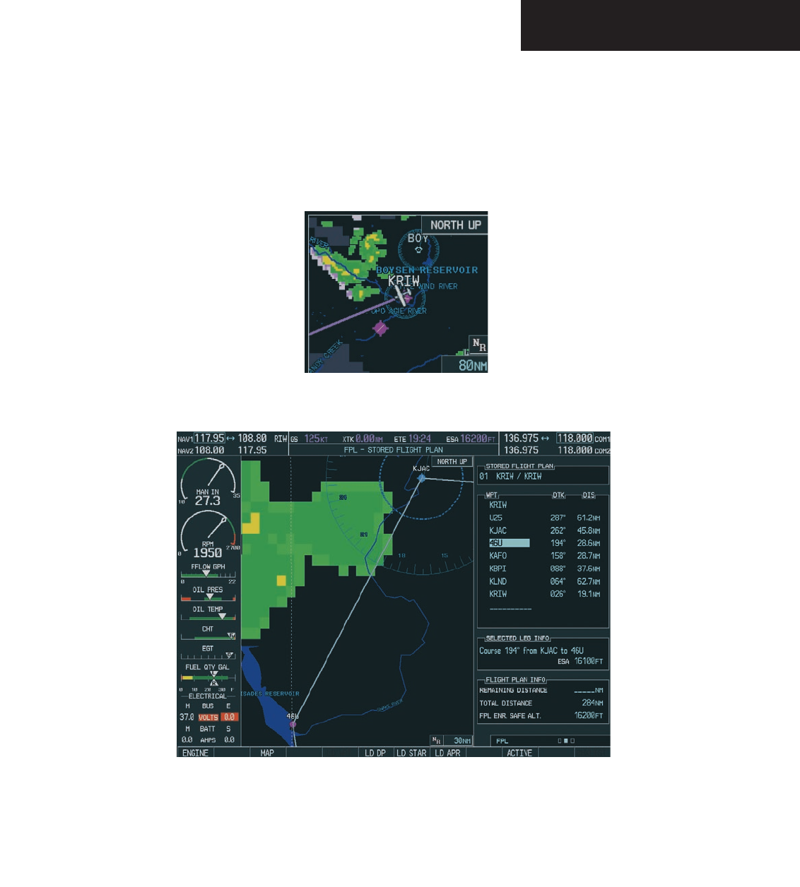
Figure 7.1.6 AUX - Trip Planning Page Map Displaying NEXRAD Weather
Figure 7.1.7 Stored Flight Plan Page Map Displaying Weather Data
Displaying Weather Data on the Flight Plan
Page Maps
NEXRAD and XM Lightning Data can be displayed on
the Flight Plan Page Maps by pressing the NEXRAD and
XM LTNG softkeys.
Preliminary
190-00498-00_0A.indd 11 3/1/2005 10:33:43 AM
Garmin G1000 Hazard Avoidance Pilot’s Guide for the Cessna Citation Mustang 190-00498-00 Draft
7-12
WEATHER
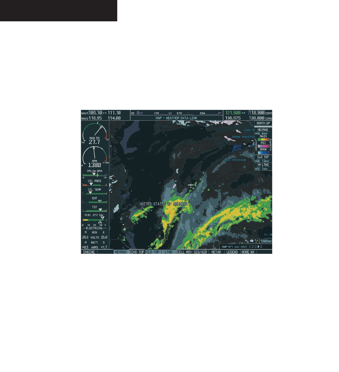
Displaying Weather on the Weather Data Link
Page
The Weather Data Link Page displays all available
weather products. The display of the weather data can
either be selected by softkeys located at the bottom of the
display or through the Weather Data Link Setup menu.
Figure 7.1.8 Weather Data Link Page
To select the Weather Data Link Page:
1. Turn the
large FMS
knob to select the Map Page
Group.
2. Turn the
small FMS
knob to select the Weather
Data Link Page.
Preliminary
190-00498-00_0A.indd 12 3/1/2005 10:33:43 AM

Garmin G1000 Hazard Avoidance Pilot’s Guide for the Cessna Citation Mustang190-00498-00 Draft 7-13
WEATHER
Weather Data Link Page Softkeys
The following softkeys perform the GDL 69A weather
functions on the Weather Data Link Page:
NEXRAD – press the NEXRAD softkey to show
NEXRAD weather and radar coverage information
(both are activated at the same time). Composite
data from all of the NEXRAD radar sites in the
United States is shown. This data is composed
of the maximum reflectivity from the individual
radar sweeps. The display of the information is
color-coded to indicate the weather level severity.
The update rate is every five minutes. Refer to the
legend for a description of the color code.
NOTE: WSR-88D weather surveillance radar
or NEXRAD (NEXt generation RADar) is a Dop-
pler radar system that has greatly improved
the detection of meteorological events such as
thunderstorms, tornadoes and hurricanes. An
extensive network of NEXRAD stations provides
almost complete radar coverage of the conti-
nental United States, Alaska and Hawaii. The
unobstructed range of each NEXRAD is 124
nautical miles.
NEXRAD Abnormalities
There are possible abnormalities regarding displayed
NEXRAD images. Some, but not all, of those include:
• Ground Clutter
• Strobes and spurious radar data
• Sun strobes, when the radar antenna points directly
at the sun
• Interference from buildings or mountains, which
may cause shadows
• Military aircraft deploy metallic dust which can
cause alterations in radar scans
NEXRAD Limitations
Certain limitations exist regarding the NEXRAD radar
displays. Some, but not all, are listed here for the crew’s
awareness:
• NEXRAD base reflectivity does not provide sufficient
information to determine cloud layers or precipita-
tion characteristics (hail vs. rain, etc).
• NEXRAD base reflectivity is sampled at the minimum
antenna elevation angle. An individual NEXRAD site
cannot depict high altitude storms at close ranges,
and has no information about storms directly over
the site.
• The resolution of displayed NEXRAD data is 2 kilo-
meters. Therefore, when zoomed in on the display,
each square block is 2 kilometers. The intensity
level reflected by the square will be the highest level
sampled within the 2 kilometer square area.
NEXRAD Intensity
Colors are used to identify the different NEXRAD echo
intensities (reflectivity) measured in dBZ (decibels of Z).
“Reflectivity” is the amount of transmitted power returned
to the radar receiver. Reflectivity (designated by the letter
Z) covers a wide range of signals (from very weak to very
strong). So, a more convenient number for calculations
and comparison, a decibel (or logarithmic) scale (dBZ), is
used. The dBZ values increase as the strength of the signal
returned to the radar increases.
Preliminary
190-00498-00_0A.indd 13 3/1/2005 10:33:44 AM
Garmin G1000 Hazard Avoidance Pilot’s Guide for the Cessna Citation Mustang 190-00498-00 Draft
7-14
WEATHER
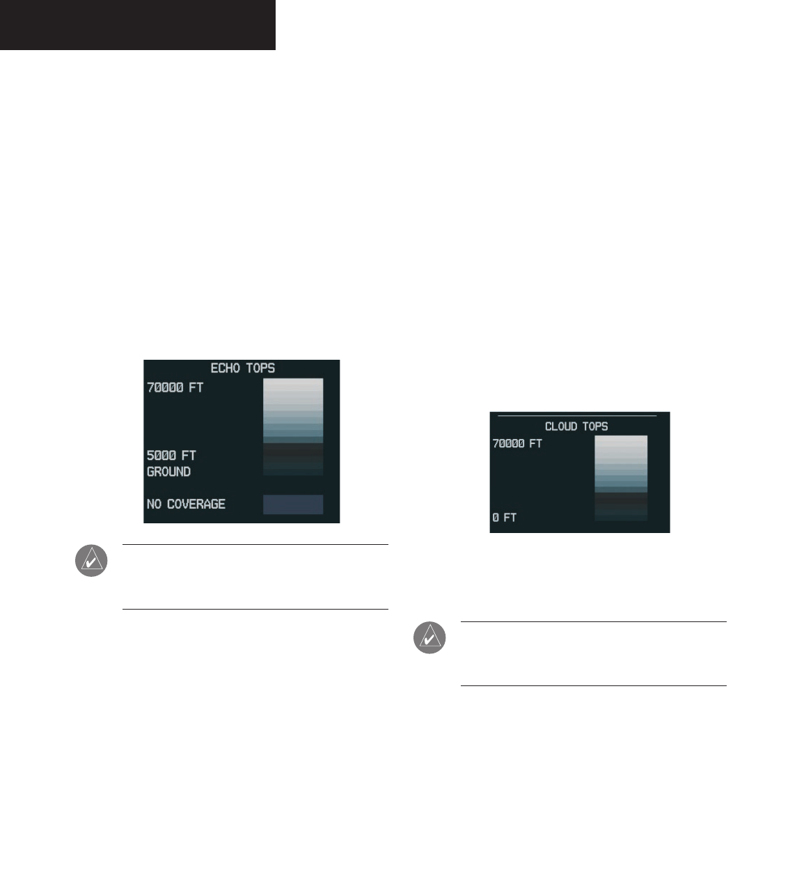
ECHO TOP – press the ECHO TOP softkey to show
the location, elevation and direction the highest
radar echo. This may not indicate the top of a
storm or clouds, only the highest radar return
echo. The information is derived from NEXRAD
information and indicates the highest altitude at
which precipitation is falling. ECHO TOPS and
Radar coverage are activated at the same time.
ECHO TOPS are mutually exclusive from both
NEXRAD and CLOUD TOPS, that is, when ECHO
TOPS is activated, NEXRAD and CLOUD TOPS
are removed. Refer to the Legend for a descrip-
tion of the ECHO TOPS coding. The update rate
is every 7.5 minutes.
NOTE: Cloud Tops and Echo Tops use the same
color scaling to represent altitude. Turning on
both products at the same time is not allowed.
RADAR COVERAGE – The display of Radar Cover-
age is always active when NEXRAD and ECHO
TOPS are selected and indicates the currently
available NEXRAD Radar coverage and ECHO
TOPS areas by showing the area in a grayish-
purple color where information is not being
collected. Areas where radar capability exists, but
is not active or is off-line, will not be shown as
available. Areas where radar coverage is not avail-
able will be shown in grayish-purple. The update
rate is every five minutes.
CLD TOP – press the CLD TOP softkey to show
the cloud top altitude determined from satellite
imagery. Refer to the legend for a description of
the CLOUD TOPS color coding. The update rate
is every 15 minutes.
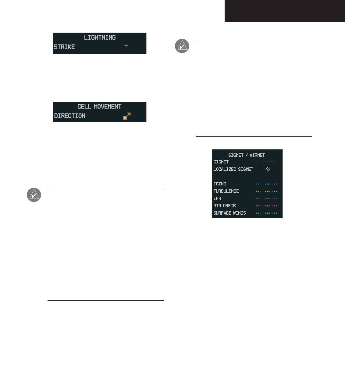
LTNG – pressing the LTNG softkey shows the loca-
tion of cloud-to-ground lightning strikes. The
update rate is every five minutes.
NOTE: Strike location falls within a 2 km region.
Therefore, the exact location of the strike is not
displayed.
Preliminary
190-00498-00_0A.indd 14 3/1/2005 10:33:44 AM
Garmin G1000 Hazard Avoidance Pilot’s Guide for the Cessna Citation Mustang190-00498-00 Draft 7-15
WEATHER
CELL MOV – pressing the CELL MOV softkey
shows the storm cells identified by the ground-
based system. The movement is depicted by an
arrow. The update rate is every 12 minutes.
SIG/AIR – pressing the SIG/AIR softkey shows
SIGMET and AIRMET information to advise
the crew of potentially hazardous weather. The
advisory covers an area of at least 3,000 square
miles at any one time. The update rate is every 12
minutes.
NOTE: SIGMETs are broadcasted for hazardous
weather that is considered of extreme importance
to all aircraft. SIGMETs (acronym for “SIGnifi-
cant METeorological information”) warn of the
following weather hazards: severe icing, severe
and extreme turbulence, dust storms, sandstorms
or volcanic ash lowering visibility to less than 3
miles. A Convective SIGMET (WST) is issued for
hazardous convective weather (such as torna-
does, thunderstorms, hail) and covers severe or
greater turbulence, severe icing and low-level
wind shear. A localized SIGMET is a significant
weather condition occurring at a localized geo-
graphical position.
NOTE: AIRMETs are broadcast for weather
phenomena that potentially affect all aircraft.
AIRMET (acronym for “AIRman’s METeorological
information) gives valuable information about
the following conditions: moderate icing, mod-
erate turbulence, sustained winds 30 knots or
greater at the surface, widespread area with a
ceiling of less than 1,000 feet and/or visibility
less than 3 miles and extensive obscurement of
mountains. These are important to light aircraft,
that have limited flight capabilities due to lack
of equipment and/or instrumentation.
Preliminary
190-00498-00_0A.indd 15 3/1/2005 10:33:44 AM
Garmin G1000 Hazard Avoidance Pilot’s Guide for the Cessna Citation Mustang 190-00498-00 Draft
7-16
WEATHER
When enabled, the following AIRMETs can be
displayed:
• Icing
• Turbulence
• IFR conditions
• Mountain obscuration
• Surface winds
Refer to the legend for a description of the color
coding.
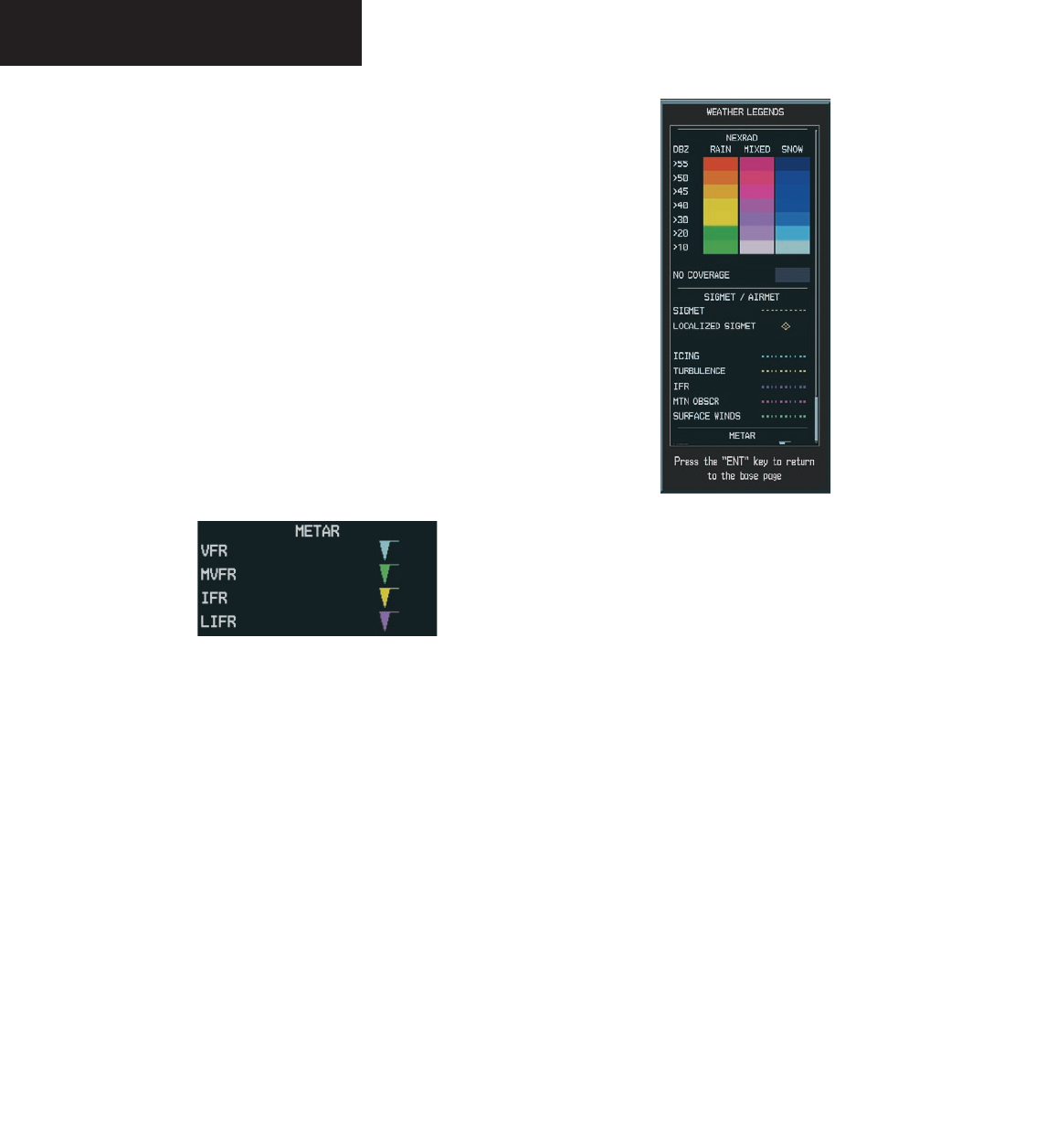
METAR – press the METAR softkey to display
METARs (METeorological Aviation Reports).
METARS are shown as colored flags at airports
providing METAR reports. Refer to the legend for
a description of the color code. The update rate is
every 12 minutes.
LEGEND – press the LEGEND softkey to display
the Weather Legend Window. Turn the FMS
knob to scroll up or down through the legend list.
Press the FMS knob or the ENT key to remove
the legend display. The Weather Legends Window
describes the graphic symbols and color coding of
the information for each product that is active.
Figure 7.1.9 Weather Legends Window
To view the available legends:
1. Press the LEGEND softkey to display the avail-
able legends.
2. Turn either the small or large FMS knob to
scroll through the legends if more are available
than fit in the window.
3. To return to the previous page and remove the
legend window, press the LEGEND, ENT, CLR
key, or the FMS knob. OR
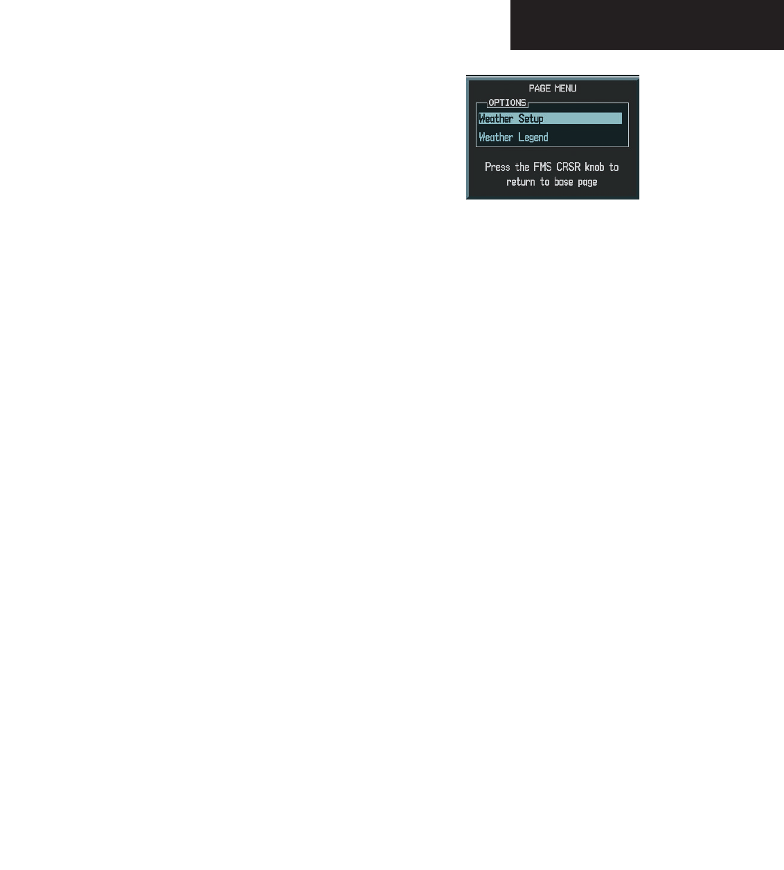
4. On the Weather Data Link Page, press the
LEGEND softkey which displays the Page Menu
Options. Turn either the large or small FMS
knob to select ‘Weather Legend’ and press the
ENT key.
Preliminary
190-00498-00_0A.indd 16 3/1/2005 10:33:45 AM
Garmin G1000 Hazard Avoidance Pilot’s Guide for the Cessna Citation Mustang190-00498-00 Draft 7-17
WEATHER
MORE WX – press the MORE WX softkey to
display the following group of softkeys for
additional weather control:
NOTE: City Forecast and METAR information
is only displayed within the installed Aviation
Database service area.
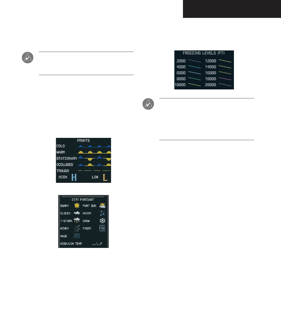
SFC – pressing the SFC softkey for Surface
Analysis shows current or forecast conditions.
The city forecasts information is combined with
the surface conditions. The SFC softkey label
changes to reflect the forecast time selected.
Forecasts are available for intervals of 12, 24,
36 and 48 hours. The update rate is every 12
minutes.
FRZ LVL – press the FRZ LVL softkey to display
contour lines for freezing levels. The update
rate is every 12 minutes.
NOTE: When no data is shown at a given altitude
for any of the weather features, the data for that
altitude has not been received or the data is out
of date and has been removed from the display.
Wait for the next update. The update rate is every
12 minutes.
Preliminary
190-00498-00_0A.indd 17 3/1/2005 10:33:45 AM
Garmin G1000 Hazard Avoidance Pilot’s Guide for the Cessna Citation Mustang 190-00498-00 Draft
7-18
WEATHER
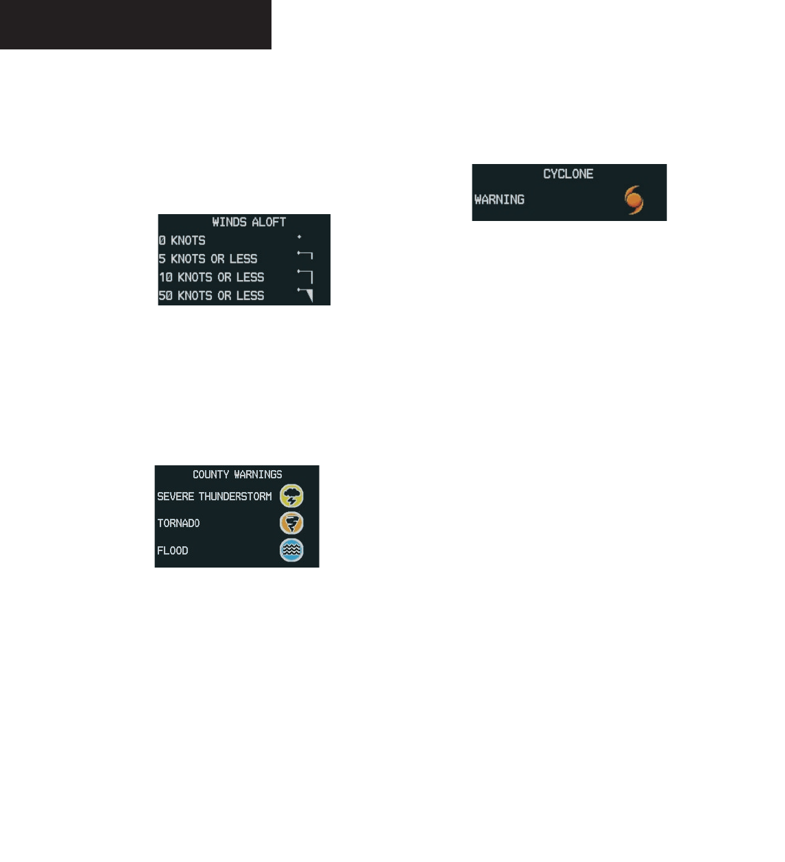
WIND – press the WIND softkey to show wind
speed and direction at a selected altitude from
the ground up to 42,000 feet in 3,000 foot
increments. The WIND softkey label changes
to reflect the winds aloft altitude selected. The
update rate is every 12 minutes.
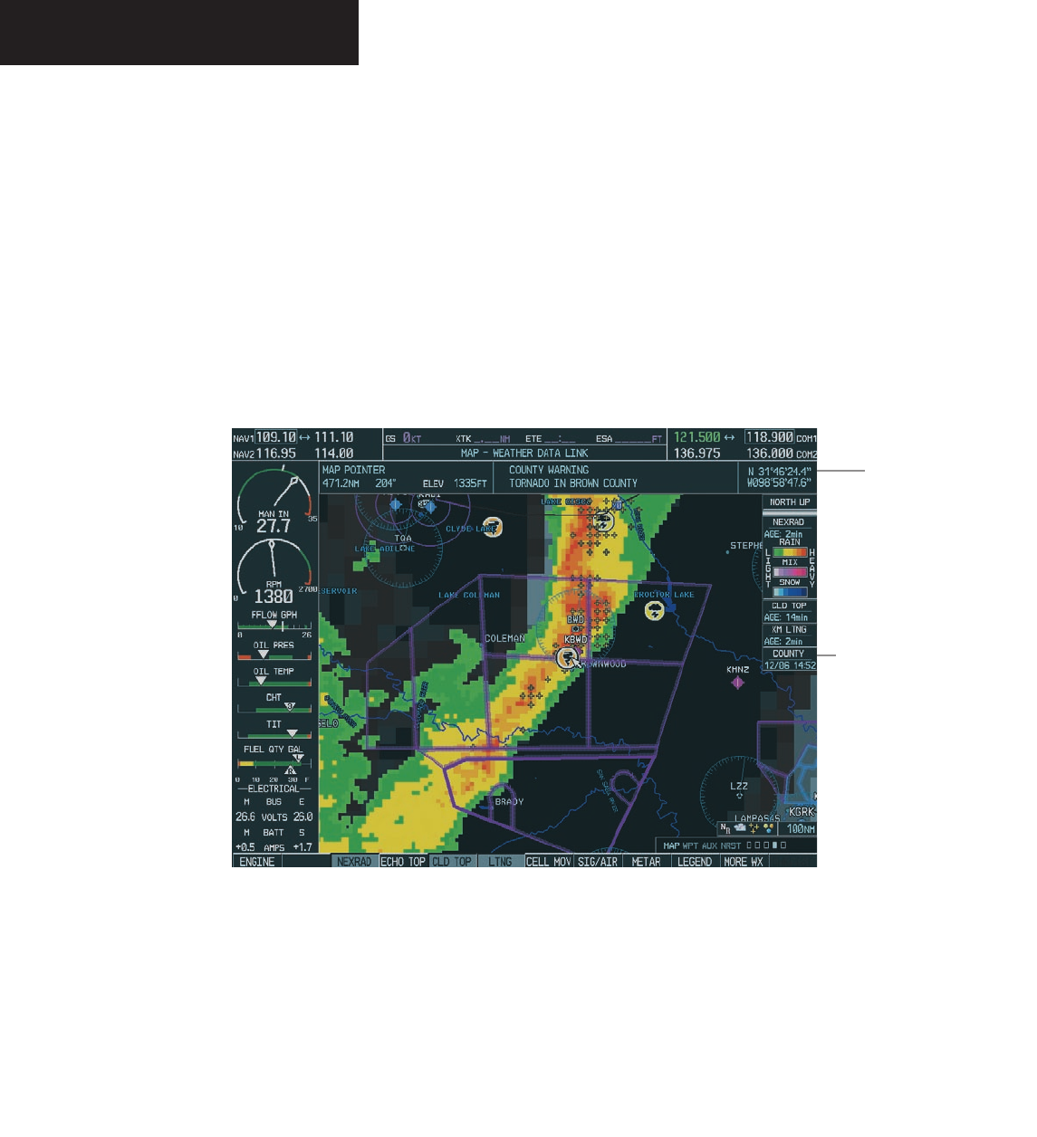
COUNTY – pressing the COUNTY softkey provides
specific public awareness and protection weather
warnings for Tornado, Severe Thunderstorm
and Flood conditions provided by the National
Weather Service (NWS). Refer to the Legend for
a description of the county warning icon. The
update rate is every 5 minutes.
CYCLONE – pressing the CYCLONE softkey shows
the current location of cyclones (hurricanes) and
their projected track at various time intervals.
The update rate is every 12 minutes.
Preliminary
190-00498-00_0A.indd 18 3/1/2005 10:33:45 AM
Garmin G1000 Hazard Avoidance Pilot’s Guide for the Cessna Citation Mustang190-00498-00 Draft 7-19
WEATHER
Weather Data Link Page Setup
The crew can customize the display of XM Weather
data on the Weather Data Link Page using the Weather
Setup Menu.
To customize the display of weather data
on the Weather Data Link Page:
1. On the Weather Data Link Page, press the
Menu key.
2. While the Weather Setup selection is high-
lighted on the Page Menu, press the ENT key.
If necessary, turn the small FMS knob to select
‘Weather Setup’ and then press the ENT key.
3. While the Weather Data Link Setup Menu is
displayed, turn the large FMS knob to high-
light and move between the product selections.
Turn the small FMS knob to select an option
for each selection and press the ENT key.
Figure 7.1.10 Weather Data Link Page Menu
Map Panning Information-Weather Data Link
Page
Map panning moves the map beyond its current limits
without adjusting the map range. When the panning
function is selected by pushing the joystick, a panning
arrow flashes on the Weather Data Link Page. Panning over
AIRMETs, County Warnings, TFRs, Echo Tops, METARs,
SIGMET’s and Cell Movement displays text information
for the selection. This information is displayed in the
same location as the “map pointer information” on the
Navigation Map Page.
Preliminary
190-00498-00_0A.indd 19 3/1/2005 10:33:45 AM
Garmin G1000 Hazard Avoidance Pilot’s Guide for the Cessna Citation Mustang 190-00498-00 Draft
7-20
WEATHER
To display information for selected weather
products:
1. Push in the
joystick
to display the panning
arrow.
2. Move the
joystick
to place the panning arrow
on AIRMETs, TFRs, METARs or SIGMETs. Press
the ENT key to display pertinent information
for the selected product.
Figure 7.1.11 Panning on the Weather Data Link Page
Panning
Information
Map Panning
Arrow
Note that pressing the ENT key when pan-
ning over an AIRMET or a SIGMET displays an
information box that gives the actual text of
that alert. Panning over an airport with METAR
information does not display more information
but allows the crew to press the ENT key and
select that Airport’s Information Page and
displays the actual text. Pressing the ENT key
when panning over a TFR displays TFR specific
information for the panned TFR.
Preliminary
190-00498-00_0A.indd 20 3/1/2005 10:33:46 AM
Garmin G1000 Hazard Avoidance Pilot’s Guide for the Cessna Citation Mustang190-00498-00 Draft 7-21
WEATHER
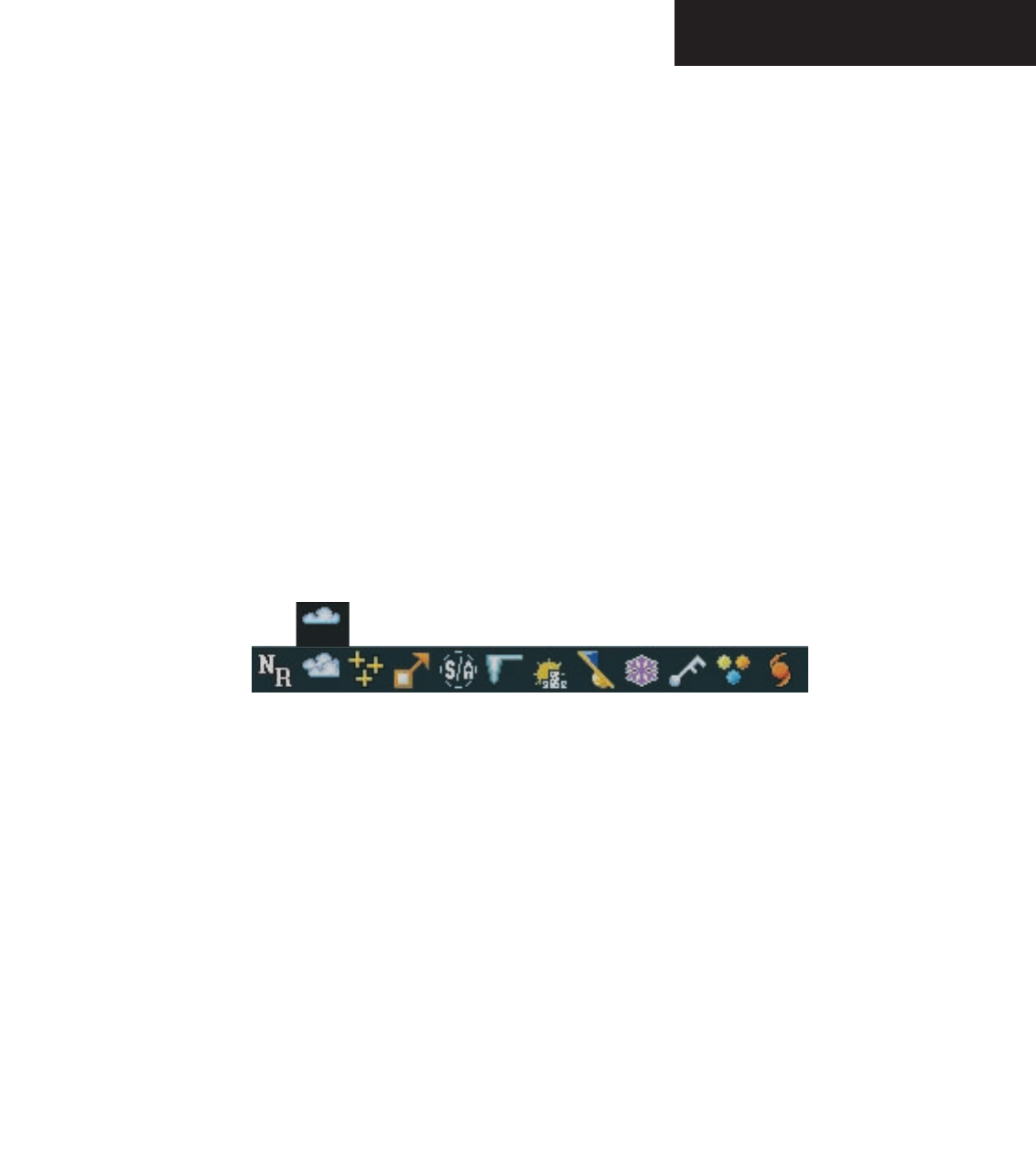
Weather Product Symbols
Figure 7.1.12 depicts the symbol for each weather
product (read from left to right). When a weather prod-
uct is active, the product symbol is displayed in the lower
right of the screen.
• NEXRAD
• Cloud Top/Echo Top
• XM Lightning
• Cell Movement
• SIGMETs/AIRMETs
• METARs
• City Forecast
• Surface Analysis
• Freezing Levels
• Winds Aloft
• County Warnings
• Cyclone Warnings
Figure 7.1.12 Weather Product Symbols
Echo Top (Cloud Top and Echo Top Mutually Exclusive)
Preliminary
190-00498-00_0A.indd 21 3/1/2005 10:33:46 AM
Garmin G1000 Hazard Avoidance Pilot’s Guide for the Cessna Citation Mustang 190-00498-00 Draft
7-22
WEATHER
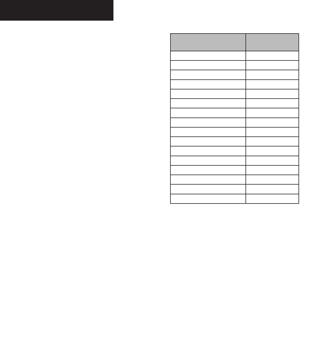
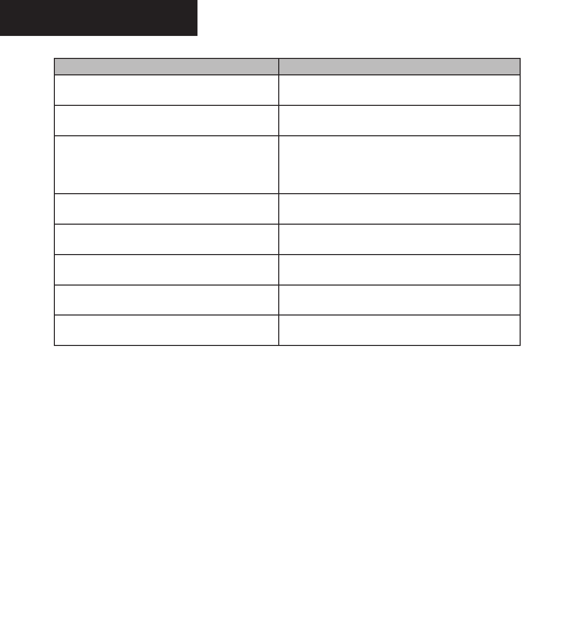
Weather Product Age
The times for each of the enabled products are displayed
on the right side of the display. Times are based on Zulu
times when the data was assembled on the ground, not the
time the data was received by the FIS sensor. When the age
of a weather product is greater than half of the expiration
time, the product time will change from cyan to amber in
color.
Current weather products use an age stamp,
‘Age: _ _ _’ in minutes. Reported (forecasted) weather
products use a date/time stamp; ‘_ _/_ _ /_ _:_ _’.
Weather Product Expires After
“n” Minutes
SIGMETs/AIRMETs 60
City Forecasts 60
County Warnings 60
Cyclone Warnings 60
Echo Tops 30
Freezing Levels 60
METARs 90
Lightning 30
NEXRAD 30
Radar Coverage 30
Cell Movement 30
Surface Analysis 60
TFRs 60
Winds Aloft 60
TAFs 60
Clouds Tops 60
Preliminary
190-00498-00_0A.indd 22 3/1/2005 10:33:46 AM

Garmin G1000 Hazard Avoidance Pilot’s Guide for the Cessna Citation Mustang190-00498-00 Draft 7-23
WEATHER
GDL 69 Troubleshooting
Although it is the responsibility of the facility that in-
stalled the GDL 69A to correct any hardware problems,
the crew can perform some quick troubleshooting steps
to find the possible cause of a failure.
First, ensure that the owner/operator of the aircraft in
which the GDL 69A is installed has subscribed to XM Ra-
dio and that it has been activated. Perform a quick check
of the circuit breakers to ensure the GDL 69A has power
applied. If a failure still exists, review the messages listed
in the table at the end of this section. The advisory mes-
sages may provide insight to a possible failure.
For troubleshooting purposes, the Status, Serial Num-
ber and Software Version numbers for the GDL 69A are
displayed in the LRU Information Window on the System
Status Page.
To select the System Status Page:
1. Turn the large FMS knob to select the AUX
Page Group.
2. Turn the small FMS knob to select the System
Status Page.
Figure 7.1.19 LRU Information Window
Preliminary
190-00498-00_0A.indd 23 3/1/2005 10:33:47 AM
Garmin G1000 Hazard Avoidance Pilot’s Guide for the Cessna Citation Mustang 190-00498-00 Draft
7-24
WEATHER
Message Description
CHECK ANTENNA – XM Radio Page, the active channel is
replaced with this message
Antenna is not connected
UPDATING – XM Radio Page, the active channel is
replaced with this message
Updating encryption code
NO SIGNAL – XM Radio Page, the active channel is
replaced with this message ; also displayed on the Weather
Data Link Page when the signal strength is too low for the
receiver
Loss of signal
LOADING – XM Radio Page, the active channel is replaced
with this message
Acquiring channel audio or information
OFF AIR – XM Radio Page, the active channel is replaced
with this message
Channel not in service
--- (XM Radio Page, the active channel is replaced with this
message )
Missing channel information
WEATHER DATA LINK FAILURE – Weather Data Link
Page, displayed in the center of the screen in yellow
No communication with the GDL 69 within the last five minutes
ACTIVATION REQUIRED – Weather Data Link Page,
displayed in the center of the screen in yellow
XM Data receiver is not activated
Table 7.1.1 Advisory Messages
Preliminary
190-00498-00_0A.indd 24 3/1/2005 10:33:47 AM
Garmin G1000 Hazard Avoidance Pilot’s Guide for the Cessna Citation Mustang190-00498-00 Draft 7-25
WEATHER
GWX 68 AIRBORNE WEATHER
RADAR
The GWX 68 Airborne Weather Radar System provides
weather detection and ground mapping capability. The
primary function of the weather radar system is to find
storms along the flight path. Weather detection gives the
crew the ability to recognize potentially dangerous thun-
derstorm cells.
The GWX 68 weather radar system also provides
ground mapping, giving the ability to distinguish land-
scape features and bodies of water.
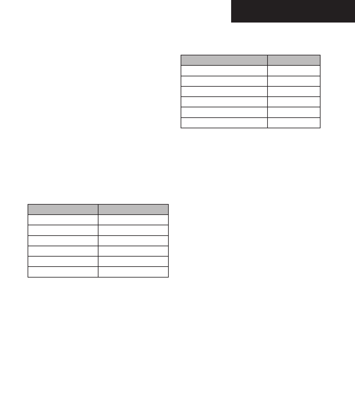
Weather radar return strength is shown in six different
colors to show intensities of rainfall (black, green, yellow,
red, magenta, and white).
Table 7.1.2 shows six different colors associated with
the levels of rainfall or storm intensity.
Rainfall Rate Color
Very Heavy Rainfall Magenta
Heavy Rainfall Red
Medium Rainfall Yellow
Light Rainfall Green
No Rainfall Black
TBS White
Table 7.1.2 Weather Radar Rainfall Rate Colors
Ground mapped radar return strength is shown using
the colors black, cyan, yellow, magenta, and blue. In the
ground mapping mode, internal parameters are selected
to increase returns from ground targets and decrease re-
turns from weather targets.
Table 7.1.3 shows six different colors associated with
levels of ground mapping return intensity.
Ground Mapping Return Color
None Black
Least Reflective Cyan
Moderate Return Yellow
Heavy Return Magenta
Very Heavy Return Red
TBS Blue
Table 7.1.3 Ground Mapping Colors
Preliminary
190-00498-00_0A.indd 25 3/1/2005 10:33:47 AM

Garmin G1000 Hazard Avoidance Pilot’s Guide for the Cessna Citation Mustang 190-00498-00 Draft
7-26
WEATHER
Operating Modes
The G1000 controls and softkeys supply all the con-
trols and functions to operate the weather radar. The ra-
dar antenna is automatically stabilized in pitch and roll
axes. The crew can manually adjust the radar tilt, gain
and range.
The crew selects the different weather radar modes.
OFF – Deenergizes the weather radar subsystem.
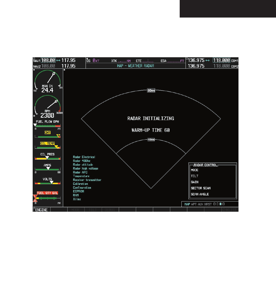
STBY – The radar is in standby, the antenna scan
stopped, the transmitter inhibited. STBY is
shown on the PFD and MFD. The RT (Receiver
Transmitter) has a warm-up period of approxi-
mately 60 seconds. If any active mode is selected
before this period, the WAIT legend will be shown
on the PFD and MFD.
WX – When selected, the radar is in the weather
detection mode. Weather data is shown on the
MFD.
GMAP (GROUND MAPPING) – In this mode,
returns from ground targets and decrease returns
from weather targets are shown.
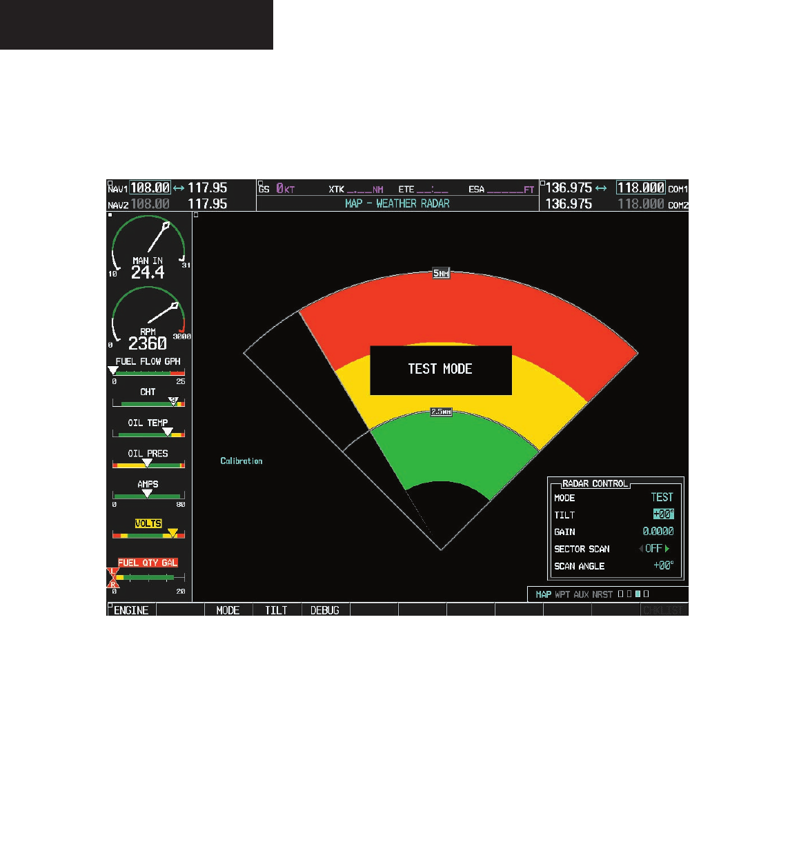
TEST – In this mode, a test pattern is shown on the
MFD to verify system operation. A TEST legend
is shown on the MFD. The transmitter radiates
microwave energy because it is on.
Preliminary
190-00498-00_0A.indd 26 3/1/2005 10:33:47 AM
Garmin G1000 Hazard Avoidance Pilot’s Guide for the Cessna Citation Mustang190-00498-00 Draft 7-27
WEATHER
Figure 7.1.20 Radar Initializing
Preliminary
190-00498-00_0A.indd 27 3/1/2005 10:33:48 AM
Garmin G1000 Hazard Avoidance Pilot’s Guide for the Cessna Citation Mustang 190-00498-00 Draft
7-28
WEATHER
When TEST mode is selected, a test pattern is shown
on the MFD to verify system operation.
Figure 7.1.21 Radar Test Pattern
Preliminary
190-00498-00_0A.indd 28 3/1/2005 10:33:48 AM
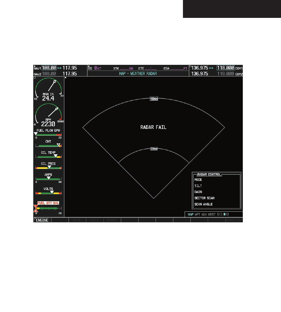
Garmin G1000 Hazard Avoidance Pilot’s Guide for the Cessna Citation Mustang190-00498-00 Draft 7-29
WEATHER
Figure 7.1.22 Radar Fail
Preliminary
190-00498-00_0A.indd 29 3/1/2005 10:33:48 AM
Garmin G1000 Hazard Avoidance Pilot’s Guide for the Cessna Citation Mustang 190-00498-00 Draft
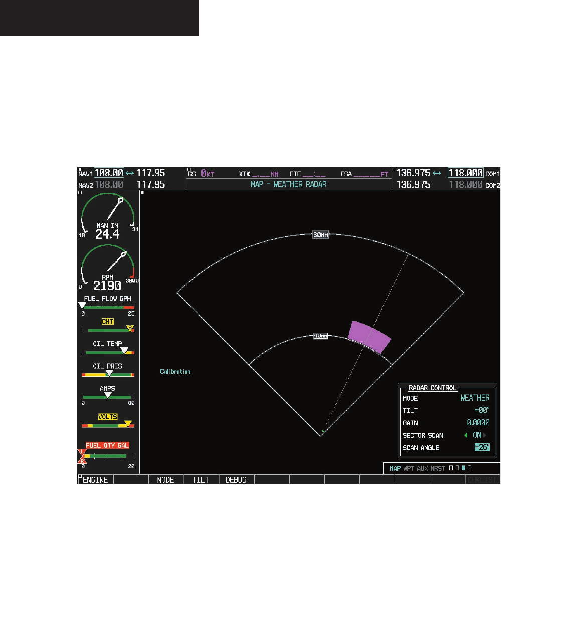
7-30
WEATHER
Figure 7.1.23 Sector Scan at +26 Degrees
Preliminary
190-00498-00_0A.indd 30 3/1/2005 10:33:49 AM

Garmin G1000 Hazard Avoidance Pilot’s Guide for the Cessna Citation Mustang190-00498-00 Draft 7-31
TAWS/TERRAIN
7.2 TAWS/TERRAIN
TAWS/TERRAIN PROXIMITY PAGE
CAUTION: Terrain and obstacle data are pro-
vided only as an aid to situational awareness.
Aural messages or textual annunciations are
displayed to the crew during flight operations
regarding the presence of terrain or obstacles.
The TAWS/Terrain Proximity Page displays the follow-
ing information:
• Current aircraft location.
• Range marking rings (1 nm, 1/2 nm, 2.5/5 nm,
5/10 nm, 12.5/25 nm, 25/50 nm, 50/100 nm
and100/200 nm).
• Heading Box (North Up, Track Up, DTK Up,
HDG Up). Heading on the TAWS/Terrain Proxim-
ity Page displays ‘HDG Up’ map data unless there
is no valid heading.
Additional TAWS only information:
• TAWS annunciator box – terrain alerts for both
warnings/caution situations and TAWS status
information.
• North arrow indicator, when not orientated in
North-Up display.
TAWS/Terrain Proximity Page Operations
There are two terrain/obstacle viewing options avail-
able (relative to the position of the aircraft), an ARC (120°)
display and a 360° default display.
To change the viewing mode between 360°
and ARC:
1. Select the TAWS/Terrain Proximity Page
2. Press the
VIEW
softkey. Then press the
ARC
softkey.
3. To return to the 360 degree viewing display
press the 360 softkey, OR:
4. Press the MENU key. The page menu is
displayed with ‘View Arc’ or ‘View 360º’
highlighted. Press the ENT key on the desired
selection.
To change the map range on the TAWS/Ter-
rain Proximity Page:
1. Turn the
joystick
clockwise to zoom out or turn
the
joystick
counter-clockwise to zoom in. Map
ranges are 1 nm, 1/2 nm, 2.5/5 nm, 5/10 nm
and 12.5/25 nm, 25/50 nm, 50/100 nm and
100/200 nm.
Preliminary
190-00498-00_0A.indd 31 3/1/2005 10:33:49 AM
Garmin G1000 Hazard Avoidance Pilot’s Guide for the Cessna Citation Mustang 190-00498-00 Draft
7-32
TAWS/TERRAIN
1000' AGL
Aircraft Altitude
100' Threshold
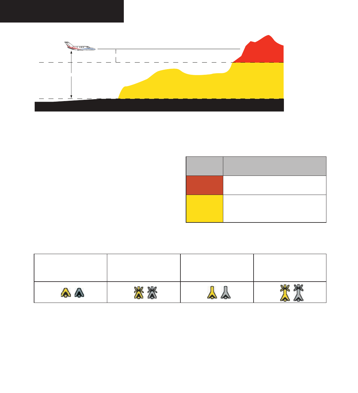
Figure 7.2.1 Terrain Scale
Displaying Obstacle Data
The TAWS/Terrain Proximity Page displays obstacle
data with heights greater than 200 feet Above Ground Lev-
el (AGL) located at their geographical position throughout
the world. Obstacles are displayed in two levels:
• CAUTION
• WARNING
Each level is associated with a color. The G1000
will adjust colors on the TAWS/Terrain Proximity Page
automatically as the aircraft altitude changes.
Obstacle Shapes
Unlighted Obstacle
(Height is less than 1000’
AGL)
Lighted Obstacle
(Height is less than 1000’
AGL)
Unlighted Obstacle
(Height is greater than 1000’
AGL)
Lighted Obstacle
(Height is greater than 1000’
AGL)
Obstacle
Color
Indication
RED WARNING: Obstacle height is at or above
100’ below the current aircraft altitude.
YELLOW
CAUTION: Obstacle height is between
100’ and 1000’ below the current aircraft
altitude.
Preliminary
190-00498-00_0A.indd 32 3/1/2005 10:33:50 AM
Garmin G1000 Hazard Avoidance Pilot’s Guide for the Cessna Citation Mustang190-00498-00 Draft 7-33
TAWS/TERRAIN
Navigation Map Display Conditions
The Map Setup Page Menu has ‘OBSTACLE DATA’ and
‘TERRAIN DATA’ feature On/Off options. The Terrain Ob-
stacle features are summarized in the table below:
Terrain
Feature
Obstacle
Feature
Navigation Map Page
OFF OFF NO OBSTACLES DISPLAYED
OFF ON CAUTION AND WARNING OBSTACLES
DISPLAYED
ON OFF CAUTION AND WARNING OBSTACLES
DISPLAYED
ON ON SAFE, CAUTION, AND WARNING
OBSTACLES DISPLAYED
NOTE: Obstacles are only displayed at certain
map zoom ranges, on certain map fields, and
will only be displayed if an obstacle database is
loaded in the system.
NOTE: The table above is only for the Navigation
Map Page. The Terrain Proximity Page always
shows ONLY caution and warning obstacles.
NOTE: Terrain data can also be displayed by
using the ‘On/Off’ Navigation Map Page option.
See the Navigation Map Page setup section for
details.
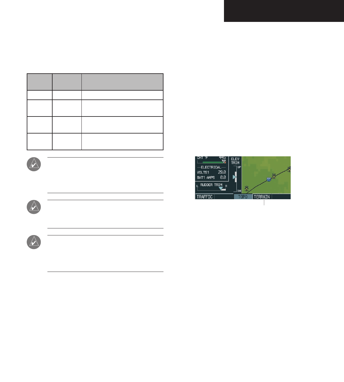
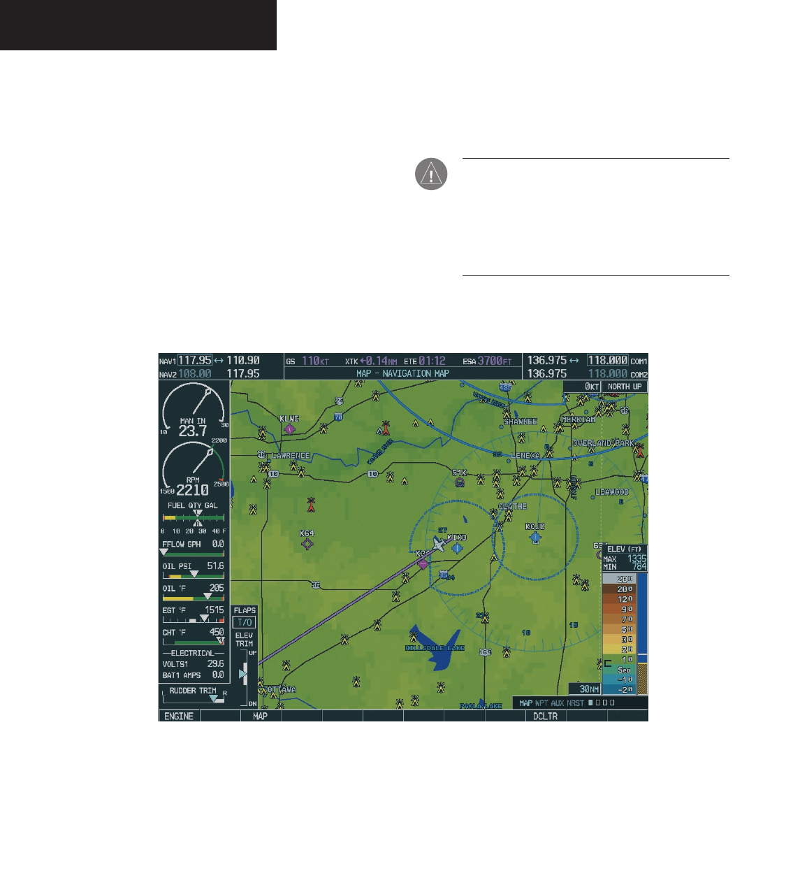
Displaying Terrain Data on the Navigation Map
Page
Terrain data can be displayed on the Navigation Map
Page by pressing the TERRAIN softkey. Terrain symbol-
ogy (mountain icon) appears next to the map range in the
bottom right corner of the page indicating the presence of
terrain data on the map.
To display terrain data on the Navigation
Map Page:
1. Press the
MAP
softkey.
2. Press the
TERRAIN
softkey. Press the
TERRAIN
softkey again to remove terrain data from the
Navigation Map Page.
TERRAIN softkey
Figure 7.2.2 TERRAIN Softkey
Preliminary
190-00498-00_0A.indd 33 3/1/2005 10:33:50 AM
Garmin G1000 Hazard Avoidance Pilot’s Guide for the Cessna Citation Mustang 190-00498-00 Draft
7-34
TAWS/TERRAIN
TAWS
Garmin’s Terrain Awareness Warning System (TAWS)
satisfies TSO-C151b Class B requirements for certifica-
tion. Class B TAWS is required for all Part 91 aircraft
operations with 6 or more seats and for Part 135 turbine
aircraft operations with 6 to 9 passenger seats (FAR Parts
91.223, 135.154). Garmin TAWS greatly increases situ-
ational awareness and aids in reducing accidental Con-
trolled Flight Into Terrain (CFIT).
Figure 7.2.3 shows the Navigation Map Page with ter-
rain features.
In order to operate properly, the Garmin TAWS/Terrain
system requires a valid 3D GPS position solution and a
valid terrain/airport terrain/obstacle database.
CAUTION: It is always the ultimate responsibility
of the crew to navigate safely throughout the
course of flight. Garmin TAWS is designed to be
an aid to situational awareness, not to be relied
on as a primary source of terrain and obstacle
avoidance.
Figure 7.2.3 Obstacles on Navigation Map Page
Preliminary
190-00498-00_0A.indd 34 3/1/2005 10:33:51 AM

Garmin G1000 Hazard Avoidance Pilot’s Guide for the Cessna Citation Mustang190-00498-00 Draft 7-35
TAWS/TERRAIN
System Compairison
Garmin TAWS and TERRAIN share several
common operational characteristics. Table 7.2.1 com-
pares the features and abilities of the two systems:
Function TAWS Terrain
TSO-C151b Class B Certified Yes No
TAWS/TERRAIN Display
( Shows terrain elevations relative to the aircraft ) Yes Yes
Visual Alerting
( Includes popup alerting ) Yes Yes
Aural Alerting Yes No
External Visual Alerting Capability Yes No
Reduced Terrain Clearance (RTC) Avoidance
( Forward Looking Terrain Avoidance (FLTA) sub-function ) Yes Yes
Imminent Terrain Impact (ITI) Avoidance
( Forward Looking Terrain Avoidance (FLTA) sub-function ) Yes Yes
Premature Descent Alert (PDA) Yes Yes
Excessive Rates of Descent
( Ground Proximity Warning System (GPWS) Alerting sub-function ) Yes No
Negative Climb Rate/Altitude Loss After Takeoff
( Ground Proximity Warning System (GPWS) Alerting sub-function ) Yes No
“Five Hundred” Voice Callout
( Ground Proximity Warning System (GPWS) Alerting sub-function ) Yes No
Inhibit Capability
( Inhibits FLTA and PDA visual and aural alerting ) Yes Yes
Manual System Test Capability Yes No
Worldwide Terrain Database Yes Yes
Airport Layer Database Yes Yes
Obstacle Database Yes Yes
Table 7.2.1 TAWS/TERRAIN Feature Comparison
Preliminary
190-00498-00_0A.indd 35 3/1/2005 10:33:51 AM

Garmin G1000 Hazard Avoidance Pilot’s Guide for the Cessna Citation Mustang 190-00498-00 Draft
7-36
TAWS/TERRAIN
Basic Operation
Power Up
During power-up of the G1000 unit, terrain/airport
terrain/obstacle database versions and area of coverage are
displayed along with a disclaimer. At the same time, the
TAWS/TERRAIN system self-test begins. An aural mes-
sage plays upon test completion:
• “TAWS System Test, OK”, if the system passes the
test.
• “TAWS System Failure”, if the system fails the
test.
A failure of the test is annunciated for both TAWS and
TERRAIN, if the self-test fails.
Database Updates
Terrain/airport terrain/obstacle databases are updated
periodically with the latest terrain/airport terrain/obstacle
data. Visit the Garmin website to check for newer versions
of terrain/airport terrain/obstacle databases. Updated ter-
rain data cards may be obtained from the Garmin website
or by calling Garmin at one of the numbers listed in the
front of this document.
Display Page Operation
TAWS and TERRAIN appears in the Navigation Map.
To display terrain data on the Navigation
Map Page:
1. Press the
MAP
softkey.
2. Press the
TERRAIN
softkey. Press the
TERRAIN
softkey again to remove terrain data from the
Navigation Map Page.
TAWS/TERRAIN/PROXIMITY Page
Terrain information, aircraft ground track and GPS-de-
rived MSL altitude are displayed on the screen. Altitude
is shown in increments of 20 feet or in increments of 10
meters, depending on unit configuration. The ‘G’ to right
of the MSL altitude display is a reminder that altitude is
GPS-derived.
There are two main display settings from
which the crew can choose:
• 360˚ View — Bird’s eye view from above aircraft
depicts surrounding terrain on all sides.
• 120˚ View — Bird’s eye view of terrain ahead of
and 60˚ to either side of the aircraft flight path.
NOTE: The TAWS/TERRAIN/PROXIMITY Page
gives a Heading Up display orientation, as indi-
cated by the ‘HDG’ label shown on the display.
To change the TAWS/TERRAIN display view-
ing angle between 360° and 120˚:
1. Select the TAWS/Terrain Proximity Page
2. Press the
VIEW
softkey. Then press the
ARC
softkey.
3. To return to the 360 degree viewing display
press the 360 softkey, OR:
4. Press the MENU key. The page menu is
displayed with ‘View Arc’ or ‘View 360º’
highlighted. Press the ENT key on the desired
selection.
Preliminary
190-00498-00_0A.indd 36 3/1/2005 10:33:51 AM
Garmin G1000 Hazard Avoidance Pilot’s Guide for the Cessna Citation Mustang190-00498-00 Draft 7-37
TAWS/TERRAIN
Terrain/Obstacle Database Areas of Coverage
The following areas of coverage are available in each
database. Regional definitions may change without no-
tice.
TAWS/TERRAIN database versions may be viewed by
going to AUX System Status Page.
Pop-up terrain alerts are displayed only when the TER-
RAIN Page is not being viewed. Pop-up terrain alerts do
not appear on the TERRAIN Page.
Worldwide (WW):
Latitudes: S60 to N75
Longitudes: W180 to E180
Americas (AME):
Latitudes: S60 to N75
Longitudes: W180 to W30
Atlantic (ATL):
Latitudes: S60 to N75
Longitudes: W30 to E90
Pacific (PAC):
Latitudes: S60 to N75
Longitudes: E60 to E180
United States (US):
Limited to the United States plus some areas of
Canada, Mexico, Caribbean, and the Pacific.
TAWS/TERRAIN Failure Alert
The TAWS/TERRAIN system continually monitors sev-
eral system-critical items, such as database validity, hard-
ware status and GPS status. Should the system detect a
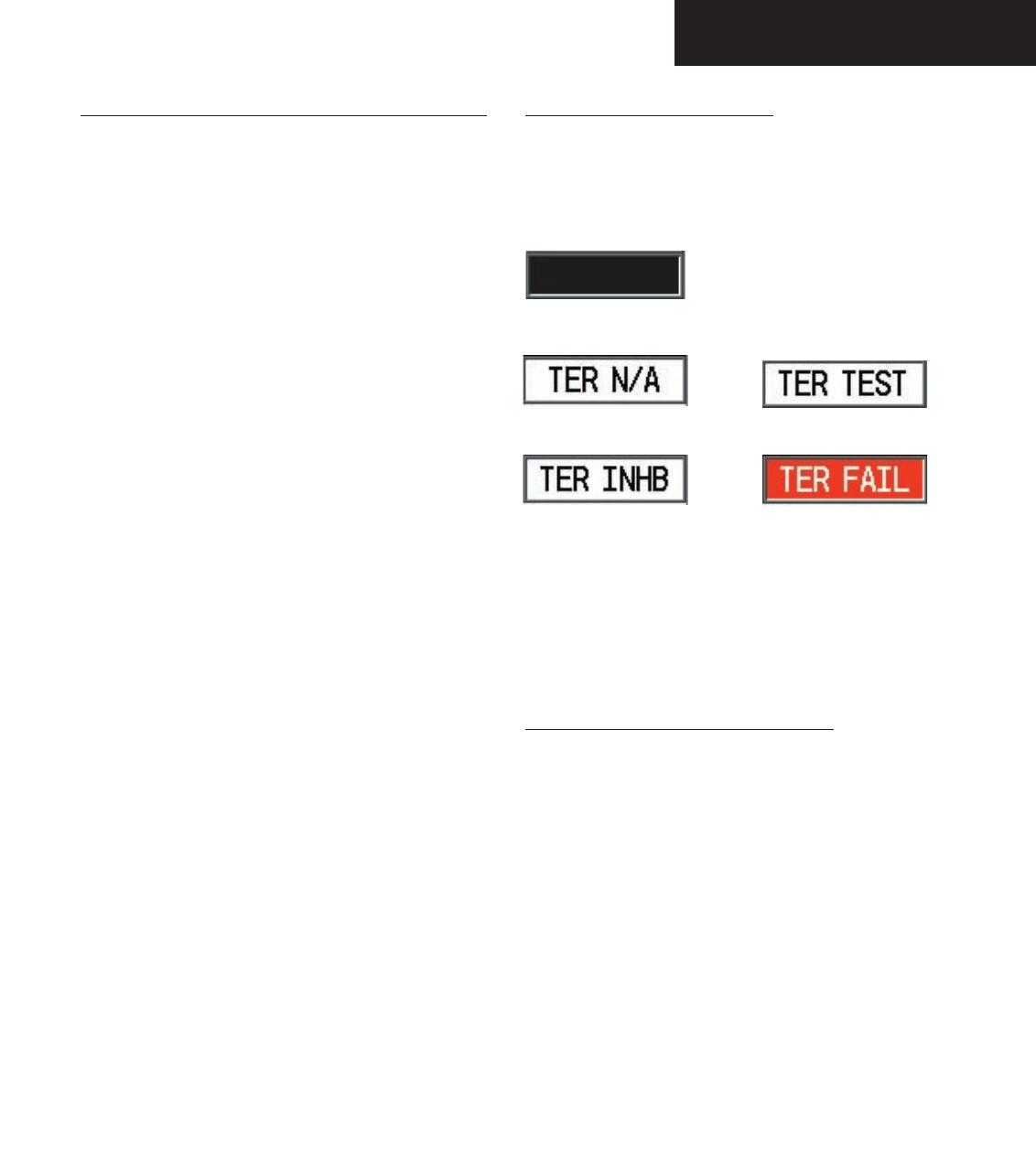
failure, one of the following messages is issued:
Terrain Inhibited Terrain Failure
Terrain Not Available Terrain Test
No Alert or Status
Figure 7.2.4 TAWS Failure Messages
The TAWS/TERRAIN Page displays “TERRAIN
FAILED”. For TAWS units, the aural message “TAWS
System Failure” is issued along with the “TER FAIL” an-
nunciation.
TAWS/TERRAIN Not Available Alert
Garmin TAWS/TERRAIN requires a 3D GPS navigation
solution along with specific vertical accuracy minimums.
Should the navigation solution become degraded, if the
terrain/airport terrain/obstacle databases are not available,
or if the aircraft is out of the database coverage area, the
annunciation ‘TER N/A’ is given in the annunciation win-
dow.
The aural message “Terrain Not Available” is issued
along with the ‘TER N/A’ annunciation.
Preliminary
190-00498-00_0A.indd 37 3/1/2005 10:33:51 AM
Garmin G1000 Hazard Avoidance Pilot’s Guide for the Cessna Citation Mustang 190-00498-00 Draft
7-38
TAWS/TERRAIN
Forward Looking Terrain Avoidance
The Forward Looking Terrain Avoidance alert (FLTA)
is used by TAWS and is composed of two sub-functions:
Reduced Required Terrain Clearance (RTC) Avoidance
— Provides alerts when the aircraft flight path is above
terrain, yet is projected to come within minimum clear-
ance values shown in Table 7.2.2. When an RTC alert is
issued, a potential impact point is displayed on the TAWS/
TERRAIN Proximity Page.
Imminent Terrain Impact (ITI) Avoidance — Provides
alerts when the aircraft is below the elevation of a terrain
cell in the aircraft’s projected path. ITI alerts are accompa-
nied by a potential impact point displayed on the TAWS/
TERRAIN Proximity Page. The alert is given when the
projected vertical flight path is calculated to come within
minimum clearance altitudes in Table 7.2.2.
During the final approach phase of flight, RTC/ITI alerts
are automatically inhibited when the aircraft is below 200’
AGL while within 0.5 nm of the approach runway or is
below 125’ AGL while within 1 nm of the runway.
Phase Of Flight Level Flight Descending
Enroute 700 ft. 500 ft.
Terminal 350 ft. 300 ft.
Approach 150 ft. 100 ft.
Departure 100 ft. 100 ft.
Table 7.2.2 Minimum Terrain Clearance Values for RTC/ITI Alerts
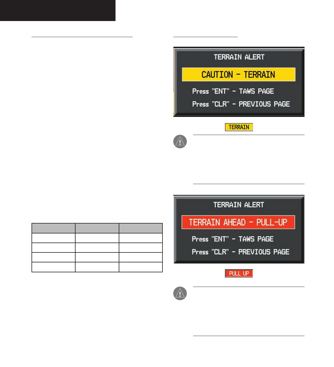
RTC/ITI Severity Levels
CAUTION: Estimated potential impact in
approximately 60 seconds after pop-up alert and
annunciation. For TAWS, RTC/ITI caution alerts
are accompanied by the aural message “Cau-
tion Terrain; Caution Terrain” OR “Terrain
Ahead; Terrain Ahead”.
WARNING: Estimated potential impact in
approximately 30 seconds after pop-up alert and
annunciation. For TAWS, RTC/ITI warning alerts
are accompanied by the aural message “Terrain,
Terrain; Pull Up, Pull Up” OR “Terrain Ahead,
Pull Up; Terrain Ahead, Pull Up”.
Preliminary
190-00498-00_0A.indd 38 3/1/2005 10:33:52 AM
Garmin G1000 Hazard Avoidance Pilot’s Guide for the Cessna Citation Mustang190-00498-00 Draft 7-39
TAWS/TERRAIN
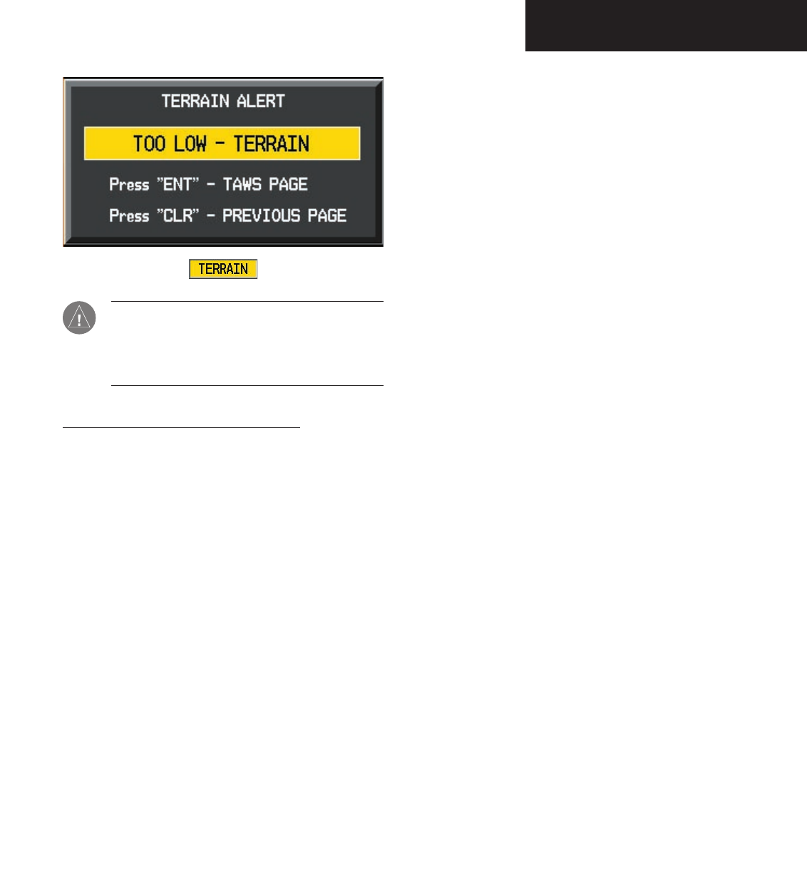
CAUTION: The above annunciation and pop-up
terrain alert are displayed during a PDA alert.
For TAWS, the PDA alert is accompanied by the
aural message “Too Low, Terrain”.
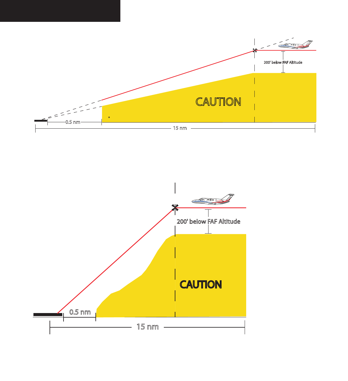
Premature Descent Alerting (PDA)
Garmin TAWS/TERRAIN issues a Premature Descent
alert when the system detects that the aircraft is signifi-
cantly below the normal approach path to a runway. The
PDA alert mode is functional only during descent to land.
There are three different scenarios to consider with PDA:
• No Approach Loaded — PDA alerting begins
when the aircraft is within 15 nm of the destina-
tion airport and ends when the aircraft is either
0.5 nm from the runway threshold OR is at an
altitude of 125’ AGL while within 1 nm of the
threshold. During the final descent, algorithms
will set a threshold for alerting based on speed,
distance and other parameters.
• Non-Precision Approach Loaded — PDA alert-
ing begins when FAF is the active waypoint AND
the aircraft is within 15 nm of the destination air-
port. Again, algorithms are used to set a threshold
for alerting based upon various parameters. PDA
alerting ends at 0.5 nm from the runway thresh-
old OR at an altitude of 125’ AGL while within 1
nm of the threshold.
• ILS Approach Loaded — PDA alerting begins
when FAF is the active waypoint AND the aircraft
is within 15 nm of the destination airport. Once
the aircraft intercepts the glideslope, PDA will
alert the crew if the aircraft descends 0.7 degrees
below the glideslope. PDA alerting ends 0.5 nm
from the runway threshold OR at an altitude of
125’ AGL while within 1 nm of the threshold.
Preliminary
190-00498-00_0A.indd 39 3/1/2005 10:33:52 AM
Garmin G1000 Hazard Avoidance Pilot’s Guide for the Cessna Citation Mustang 190-00498-00 Draft
7-40
TAWS/TERRAIN
The threshold for the Non-Precision Approach PDA de-
scent is computed by algorithms based on varying flight
conditions.
Figure 7.2.5: Example of PDA alert threshold for ILS approach
Runway Threshold
Final Approach Fix
200'belowFAFAltitude
15nm
CAUTION
PDA Alert is
0.7 Below Glideslope
Glideslope Intercept
0.5nm
0.5nm
Runway Threshold
Final Approach Fix
200'belowFAFAltitude
15nm
CAUTION
Figure 7.2.6: Example of Non-Precision Approach PDA alert threshold.
Preliminary
190-00498-00_0A.indd 40 3/1/2005 10:33:54 AM
Garmin G1000 Hazard Avoidance Pilot’s Guide for the Cessna Citation Mustang190-00498-00 Draft 7-41
TAWS/TERRAIN
TAWS Alerts
The following features are required to meet Class B re-
quirements for a TAWS system per TSO-C151b. TAWS
provides aural voice alerts along with regular display an-
nunciation. With each alert type shown is an accompany-
ing aural alert as well.
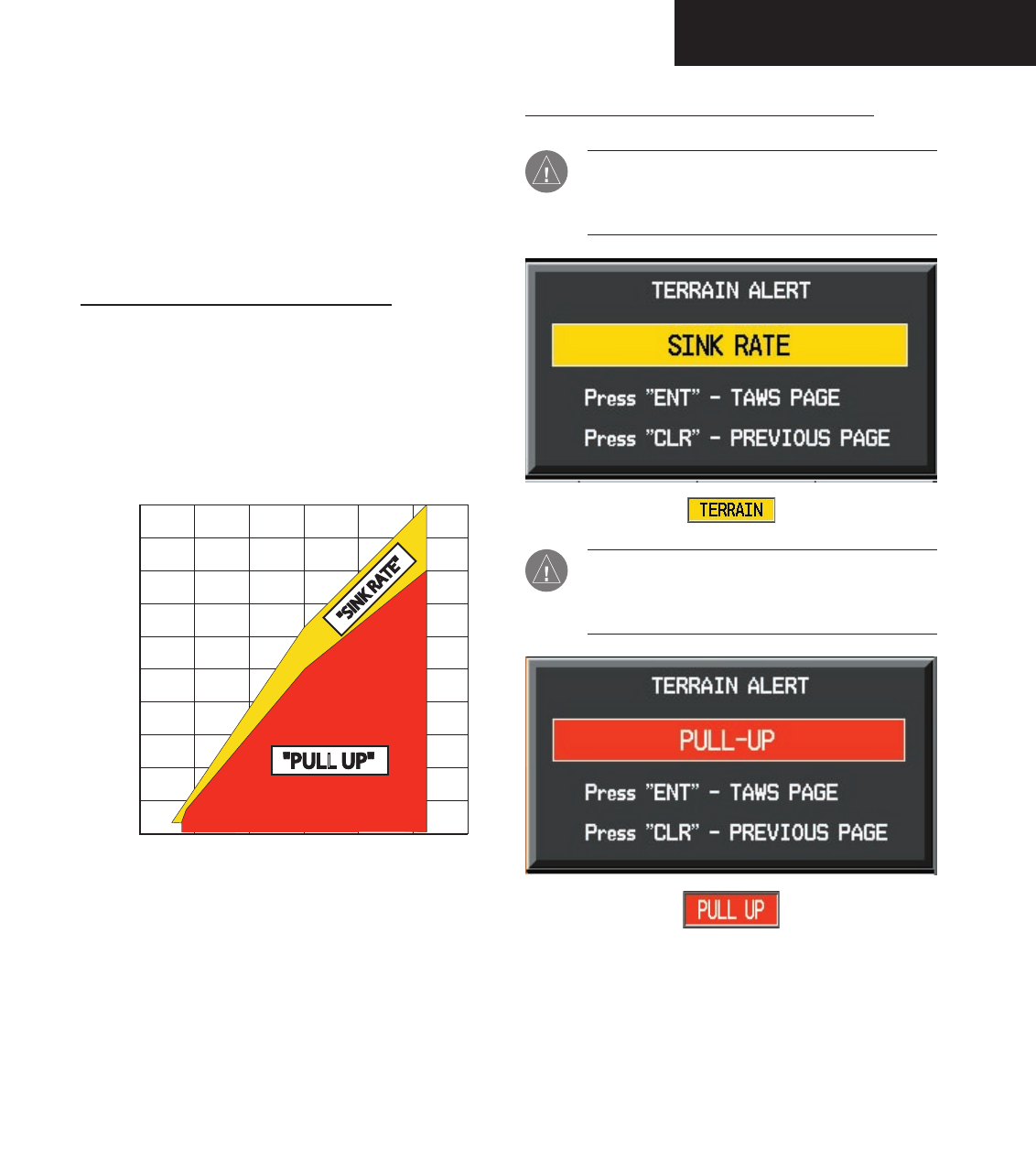
Excessive Descent Rate Alert (EDR)
The purpose of the Excessive Descent Rate alert is
to provide suitable alerts when the aircraft is deter-
mined to be closing (descending) upon terrain at an
excessive speed. Figure 7.2.7 shows the parameters
for the alert as defined by TSO-C151b.
5000
4500
4000
3500
3000
2500
2000
1500
1000
500
02000 4000 6000 8000 10000 12000
"PULL UP""PULLUP"
"SINKRATE"
Descent Rate (FPM)
Height Above Terrain (Feet)
Excessive Descent Rate Severity Levels
CAUTION: The annunciation and pop-up terrain
alert are accompanied by the aural message
“Sink Rate”.
WARNING: The annunciation and pop-up terrain
alert are accompanied by the aural message “Pull
Up”.
Figure 7.2.7: Excessive Descent Rate Graph
Preliminary
190-00498-00_0A.indd 41 3/1/2005 10:33:55 AM
Garmin G1000 Hazard Avoidance Pilot’s Guide for the Cessna Citation Mustang 190-00498-00 Draft
7-42
TAWS/TERRAIN
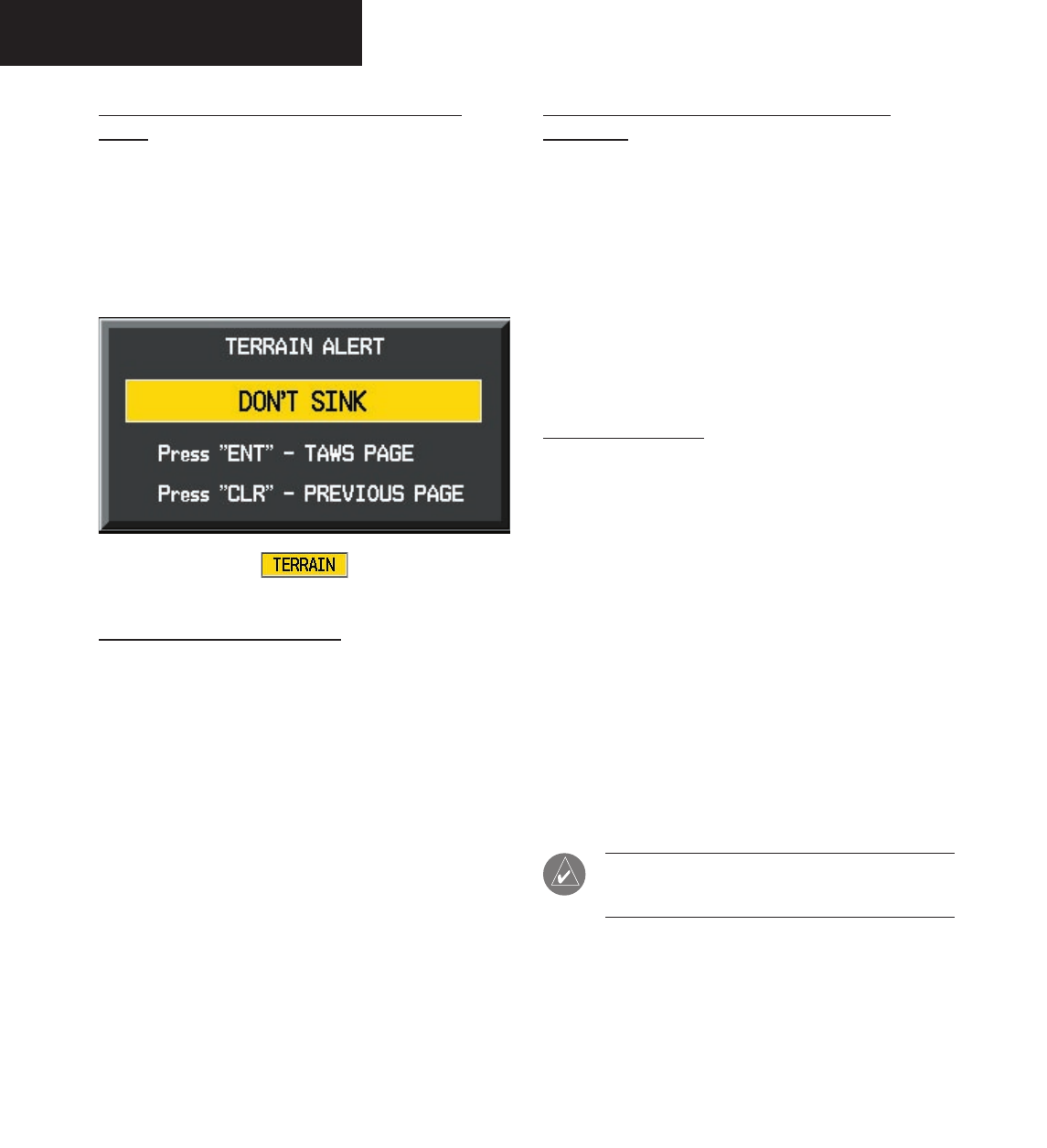
Negative Climb Rate After Takeoff Alert
(NCR)
The purpose of the Negative Climb Rate After Takeoff
alert is to provide suitable alerts to the crew when the
system determines that the aircraft is losing altitude (clos-
ing upon terrain) after takeoff. The aural message “Don’t
Sink” is given for NCR alerts, accompanied by an annun-
ciation and a pop-up terrain alert on the display.
“Five-Hundred” Aural Alert
The purpose of the aural alert message “Five-hundred”
is to provide an advisory alert to the crew that the aircraft
is five-hundred feet above terrain. When the aircraft de-
scends within 500 feet of terrain, the aural message “Five-
hundred” is heard. There are no display annunciations or
pop-up alerts that accompany the aural message.
Alert Priority and Aural Alert Message
Summary
TSO-C151b requires the establishment of an internal
priority scheme for alerts. In this way, the more important
alerts will override lesser alerts. Table 7.2.3 shows the
alert priority level in the Garmin TAWS system and gives
a summary of the aural messages.
The aural alert is configurable for either male or female
voice. Different alert text phrases are available for several
alerts. Contact a Garmin authorized service center for fur-
ther information on configuring the alert system.
TAWS System Test
Garmin TAWS provides a manual test for the flight
crew. With this feature, the crew can verify proper opera-
tion of the aural and visual system annunciation.
To manually test the TAWS system:
1. At the TAWS Page, press MENU.
2. Select the “Test Terrain?” option.
3. Press ENT to confirm the selection.
An aural message is played giving the test results:
• “TAWS System Test, OK”, if the system passes the
test.
• “TAWS System Failure”, should the system fail the
test.
NOTE: TAWS System Testing is disabled
during flight.
Preliminary
190-00498-00_0A.indd 42 3/1/2005 10:33:55 AM

Garmin G1000 Hazard Avoidance Pilot’s Guide for the Cessna Citation Mustang190-00498-00 Draft 7-43
TAWS/TERRAIN
Priority Alert Type Aural Message
1 Excessive Descent Rate Alert
Warning
“Pull Up”
2 Terrain Awareness Warning: RTC ITI Alerts “Terrain, Terrain; Pull-Up, Pull-Up”
Or
“Terrain Ahead, Pull-Up; Terrain Ahead, Pull-Up”
3 Obstacle Awareness Warning: ROC, IOI “Obstacle, Obstacle; Pull-Up, Pull-Up”
Or
“Obstacle Ahead, Pull-Up; Obstacle Ahead, Pull-Up”
4 Terrain Awareness Caution: RTC, ITI Alerts “Caution, Terrain; Caution, Terrain”
Or
“Terrain Ahead; Terrain Ahead”
5 Obstacle Awareness Caution: ROC, IOI “Caution, Obstacle; Caution, Obstacle”
Or
“Obstacle Ahead; Obstacle Ahead”
6 PDA Caution Alert “Too Low, Terrain”
7 Altitude Callout “500” “Five-hundred”
8 Excessive Descent Rate Alert Caution “Sink Rate”
9 Negative Climb after Takeoff Alert “Don’t Sink” or “Too Low, Terrain”
Table 7.2.3: TAWS Alert Summary
Preliminary
190-00498-00_0A.indd 43 3/1/2005 10:33:55 AM

Garmin G1000 Hazard Avoidance Pilot’s Guide for the Cessna Citation Mustang 190-00498-00 Draft
7-44
TAWS/TERRAIN
This page intentionally left blank.
Preliminary
190-00498-00_0A.indd 44 3/1/2005 10:33:55 AM

Garmin G1000 Hazard Avoidance Pilot’s Guide for the Cessna Citation Mustang190-00498-00 Draft 7-45
TRAFFIC
7.3 TRAFFIC
TIS (TRAFFIC INFORMATION SYSTEM)
TIS is a system used for detecting and tracking
aircraft in the vicinity of your own aircraft. When ATC
radar interrogates aircraft transponders, the replies are
analyzed to determine range, bearing and the relative
altitude of the intruder. The traffic is then displayed to
the flight crew on the MFD.
CAUTION: TIS is unable to detect any intruding
aircraft without an operating transponder.
NOTE: Traffic Information Service (TIS) is not
available in all areas.
TRANSPONDER STATUS BAR
TIS surveillance data is up-linked by Air Traffic Con-
trol (ATC) radar through the GTX 33 Mode S Transpon-
der. The Transponder Status Bar displays the transponder
code, reply symbol and mode of operation on the Inset
Map (PFD) and the Navigation and Traffic Map Pages on
the MFD (refer to the MFD Pilot’s Guide).
In order to receive and display TIS traffic information,
the GTX 33 must not be in GND mode or STBY mode.
Figure 7.3.1 Transponder Status Bar
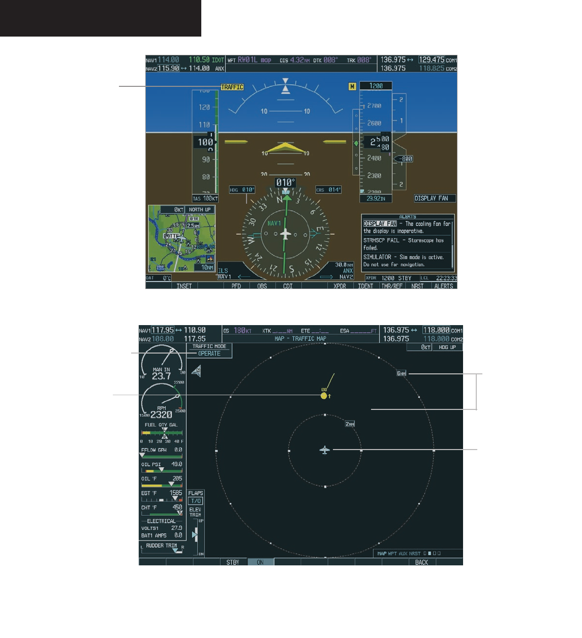
When traffic is displayed within the TIS volume, the
word TRAFFIC appears on the PFD. Figure 7.3.2 shows
the Traffic Annunciation on the PFD.
TRAFFIC MAP PAGES
The Traffic Map Page displays the following informa-
tion:
• Current aircraft location, surrounding TIS traffic,
and range marking rings.
• The current traffic mode (OPERATE, STANDBY).
• A traffic alert message (FAILED, DATA FAILED,
NO DATA, UNAVAILABLE).
• Traffic display banner (AGE 00:, TRFC COAST,
TA OFF SCALE, TRFC RMVD, TRFC FAIL, NO
TRFC DATA, TRFC UNAVAIL, TRAFFIC).
To select the Traffic Map Page:
1. Select the MAP group of pages. Turn the
small
FMS
knob to select the Traffic Map Page.
To display traffic on the Navigation Map
Page:
1. Press the
MAP
softkey.
2. Press the
TRAFFIC
softkey. Press the
TRAFFIC
softkey again to remove traffic.
NOTE: Traffic and terrain data can also be
displayed by using the ‘On/Off’ Navigation Map
Page option. See the Navigation Map Page setup
section for details.
Figure 7.3.3 shows the Traffic Map Page on the MFD.
Traffic symbols are similarly displayed on the Naviga-
tion map page. The traffic symbols are shown relative to
other displayed features.
Preliminary
190-00498-00_0A.indd 45 3/1/2005 10:33:55 AM
Garmin G1000 Hazard Avoidance Pilot’s Guide for the Cessna Citation Mustang 190-00498-00 Draft
7-46
TRAFFIC
Figure 7.3.2 Traffic Annunciation on PFD
Traffic
Annunciation
Map Range
Own Aircraft
Traffic Mode
Traffic
Figure 7.3.3 Traffic Map Page
Preliminary
190-00498-00_0A.indd 46 3/1/2005 10:33:56 AM
Garmin G1000 Hazard Avoidance Pilot’s Guide for the Cessna Citation Mustang190-00498-00 Draft 7-47
TRAFFIC
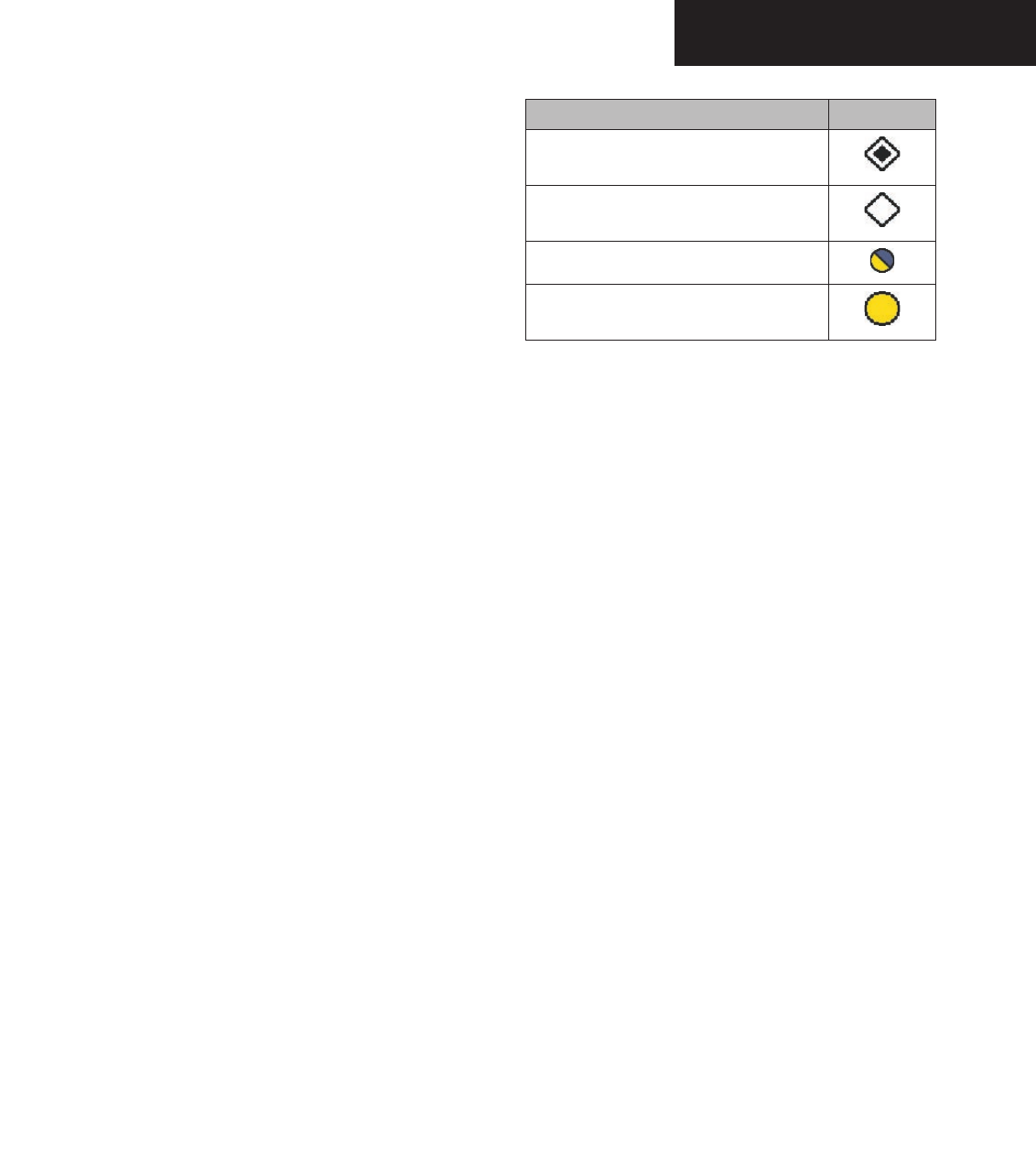
TIS Symbology
TIS traffic is displayed on the Traffic Map Page simi-
larly to TCAS symbology. The main difference between
TIS and TCAS is the source of surveillance data. TCAS
uses an airborne interrogator with a half-second update
rate. TIS uses the terminal Mode S ground interrogator
and its Data Link to provide approximately a five-second
update rate. The range accuracy of TIS and TCAS is simi-
lar. Appendix E describes the Traffic Information Service
in detail.
The Traffic Advisory (TA) solid yellow circle indicates
that traffic meets the TA advisory criteria. The presence
of TA traffic beyond the selected display range is indicated
by one half of a yellow circle at the edge of the display.
The position of the half-symbol represents the bearing of
the traffic.
Altitude separation from your aircraft is displayed
above the target symbol if the traffic is above your alti-
tude or below the symbol if they are below. Altitude trend
is displayed as an up arrow (+500 ft/min), down arrow
(-500 ft/min) or no symbol if less than 500 ft/min rate in
either direction.
Traffic Ground Track is indicated on the Traffic Map
Page by a “Track Vector”. The track vector line is pro-
jected from the TA symbol at the angle of the TA relative
track.
Proximate traffic is shown as a white diamond with
a solid box inside. Other traffic is displayed as a hollow
white diamond. Proximate traffic and other traffic sym-
bols indicate that traffic is not yet considered a threat, so
no Traffic Advisory is generated.
Category Symbol
Other Traffic
Proximate Traffic
Traffic Advisory, Out of Range
Traffic Advisory
Traffic Map Page Operations
Power-Up Test
The TIS interface performs an automatic test during
power-up. If the system passes the power-up test, the
standby screen is displayed on the Traffic Map Page. If
the system passes the power-up test while the aircraft is
airborne, traffic is immediately displayed on the Traffic
Page in the operating mode.
If the system fails the power up test, the ‘NO DATA’,
‘DATA FAILED’ or ‘FAILED’ message is displayed.
• The ‘FAILED’ message indicates the GTX 33 tran-
sponder has failed.
• The ‘DATA FAILED’ message indicates data is
being received from the GTX 33 but a failure was
detected in the data stream.
• The ‘NO DATA’ message indicates that data is not
being received from the GTX 33.
Contact a Garmin authorized service center for repair.
Preliminary
190-00498-00_0A.indd 47 3/1/2005 10:33:57 AM

Garmin G1000 Hazard Avoidance Pilot’s Guide for the Cessna Citation Mustang 190-00498-00 Draft
7-48
TRAFFIC
Changing the Map Range
To change the map range:
1. Turn the joystick clockwise to zoom out or turn
the joystick counter-clockwise to zoom in. Map
ranges are 2 nm, 6 nm and 12 nm.
NOTE: If the intruder aircraft is non-altitude
reporting only the range and bearing will be
displayed.
Operating Mode
Once the aircraft is airborne the system switches from
ground or standby mode to operating mode. The G1000
displays ‘OPERATE’ in the upper left hand corner of the
display and begins to display traffic on the Traffic or Map
Page.
The TIS Traffic Advisory (TA) should alert the crew
to look for intruding aircraft any time a yellow circle
traffic symbol appears and voice warning is announced.
Conduct a visual search for the intruder. Maintain
visual contact to ensure safe separation.
When the aircraft is on the ground the system switches
from operating mode to ground or standby mode. The
Traffic Map Page displays ‘GND’ or ‘STANDBY’.
• STANDBY – when the Traffic Map Page displays
‘STANDBY’ in the status box on the Traffic Map
Page, the TIS system is in standby mode and
cannot display traffic data.
• GND – when the Traffic Map Page displays ‘GND’
in the status box on the Traffic Map Page, the TIS
system does not display traffic data. The GTX 33
does not reply to Mode A or Mode C interroga-
tions but does send Mode S acquisition replies.
The ground mode is entered automatically. It is
not a crew selectable mode.
• OPERATE – when the Traffic Map Page displays
‘OPERATE’ in the status box on the Traffic Map
Page, the TIS system is operational and displays
traffic on the Traffic and Map Pages.
The crew can switch between the standby (STBY) and
operate (ON) modes to manually override automatic op-
eration using the page menu or softkeys.
To switch between operating modes:
1. Press the
MODE
softkey.
2. Press the
STBY
or
ON
softkey to switch between
modes. ‘STANDBY’ or ‘OPERATE’ is displayed
in the status box located in the upper left
corner of the Traffic Map Page, OR:
3. Press the
MENU
key. The page menu is
displayed with ‘Standby Mode’ or ‘Operate
Mode’ highlighted. Press the
ENT
key on the
desired selection.
Preliminary
190-00498-00_0A.indd 48 3/1/2005 10:33:57 AM

Garmin G1000 Hazard Avoidance Pilot’s Guide for the Cessna Citation Mustang190-00498-00 Draft 7-49
TRAFFIC
TIS Audio Alert
A TIS audio alert is generated whenever the number of
TAs on the Traffic Map Page display increases. Limiting
audio to TAs only reduces the amount of nuisance alert-
ing due to proximate aircraft. For example, when the first
TA is displayed, the crew is alerted audibly. As long as a
single TA aircraft remains on the TIS display, no further
audio alert is generated. If a second TA aircraft appears on
the display, a new audio alert is sounded. If the number
of TAs on the TIS display decreases and then increases, a
new audio alert is sounded. The TIS audio alert is also
generated whenever TIS service becomes unavailable.
The volume of the audio alerts and the choice between
a male or female voice is configured during installation.
The following TIS audio alerts are available:
• “Traffic” - TIS traffic alert is received.
• “Traffic Not Available” - TIS service is not available
or out of range.
TIS Traffic Status
The MFD indicates the following TIS traffic status to
the flight crew.
Traffic Banner
• AGE - if traffic data is not refreshed within 6
seconds, an age indicator (i.e., ‘AGE 00:06’) is
displayed in the lower left corner of the display,
when displaying traffic. After another 6 seconds,
if data is still not received, the traffic is removed
from the display. The quality of displayed traffic
is reduced as the traffic data becomes stale.
• TRFC COAST - the ‘TRFC COAST’ (traffic coast-
ing) banner located above the AGE timer indicates
that displayed traffic is held even though the
data is stale. The quality of displayed traffic is
reduced.
• TRFC RMVD - the ‘TRFC RMVD’ banner indicates
that traffic has been removed from the display due
to the age of the data. Data is too old to “coast”
when the time period is 12-60 seconds from the
last receipt of a TIS message. The crew should be
aware that traffic may be present but not shown.
• TA OFF - the ‘TA OFF’ scale banner displayed in
the lower left corner of the display indicates that
a traffic advisory is outside the selected display
range. The traffic advisory off-range banner is
removed when the traffic advisory is within the
selected display range.
• TRAFFIC - on the PFD, when the system receives
a traffic advisory a flashing ‘TRAFFIC’ alert is
displayed in the upper left hand portion of the
display. The PFD inset map also automatically
displays traffic data.
CAUTION: TIS warns the crew with voice and
visual traffic advisories whenever it predicts an
intruder to be a threat. The display and advi-
sories are intended only for assistance in visu-
ally locating the traffic and lack the resolution
and coordination ability necessary for evasive
maneuvering. Always attempt to visually clear
the airspace before maneuvering your aircraft in
response to a TA. See Appendix E for detailed
TIS information.
Preliminary
190-00498-00_0A.indd 49 3/1/2005 10:33:57 AM

Garmin G1000 Hazard Avoidance Pilot’s Guide for the Cessna Citation Mustang190-00498-00 Draft
Preliminary
190-00498-00_0A.indd 3 3/1/2005 10:33:57 AM

Garmin International, Inc.
1200 East 151st Street
Olathe, KS 66062, U.S.A.
p: 913.397.8200 f: 913.397.8282
Garmin AT, Inc.
2345 Turner Road SE
Salem, OR 97302, U.S.A.
p: 503.391.3411 f: 503.364.2138
Garmin (Europe) Ltd.
Unit 5, The Quadrangle
Abbey Park Industrial Estate
Romsey, SO51 9DL, U.K.
p: 44/0870.8501241 f: 44/0870.8501251
Garmin Corporation
No. 68, Jangshu 2nd Road
Shijr, Taipei County, Taiwan
p: 886/2.2642.9199 f: 886/2.2642.9099
www.garmin.com
190-00498-00 Rev. A© 2005 Garmin Ltd. or its subsidiaries
190-00498-00_0A.indd 4 3/1/2005 10:34:04 AM