Garmin 01178 Remote Control User Manual 190 00355 02 0F
Garmin International Inc Remote Control 190 00355 02 0F
Garmin >
Contents
- 1. Install Manual Cover and Info
- 2. Install Manual Sect 1
- 3. Install Manual Sect 2
- 4. Install Manual Sect 3 and 4
- 5. Users Guide
Install Manual Cover and Info
190-00355-02 December 2007 Rev. F

This Page Intentionally Left Blank
GDL 69/69A Installation Manual Page iii
190-00355-02 Rev. F
© 2006-2007 Garmin Ltd. or its subsidiaries
All Rights Reserved
Except as expressly provided herein, no part of this manual may be reproduced, copied, transmitted,
disseminated, downloaded or stored in any storage medium, for any purpose without the express prior
written consent of Garmin. Garmin hereby grants permission to download a single copy of this manual
and of any revision to this manual onto a hard drive or other electronic storage medium to be viewed and
to print one copy of this manual or of any revision hereto, provided that such electronic or printed copy of
this manual or revision must contain the complete text of this copyright notice and provided further that
any unauthorized commercial distribution of this manual or any revision hereto is strictly prohibited.
Garmin International, Inc.
1200 E. 151st Street
Olathe, KS 66062 USA
Telephone: 913.397.8200
Aviation Panel-Mount Technical Support Line (Toll Free) 1.888.606.5482
www.garmin.com
Garmin (Europe) Ltd.
Liberty House
Bull Copse Road
Hounsdown Business Park
Southampton, SO40 9RB, UK
Telephone: + 44(0) 870 850 1243
Garmin AT, Inc.
2345 Turner Rd., SE
Salem, OR 97302 USA
Telephone: 503.581.8101
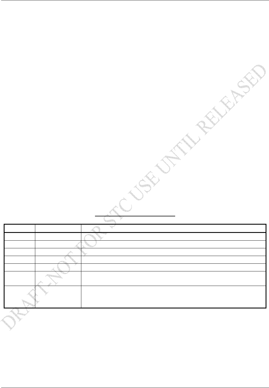
RECORD OF REVISIONS
Revision Revision Date Description
1 12/3/04 Experimental Release
A 12/8/04 Production Release
B 2/3/05 Add 400/500 interface
C 7/27/05 Add GDU 104x interface and SW version 3.00
D 9/15/05 Corrected specification sheet
E 6/30/06 Remove XM antenna installation data and added GA 55A and
GA 57 antenna references.
F 12/13/07 Add GRC 10 and GRT 10 remote system and conditional use of
Discrete 1 and 2. Update symbology of wiring diagrams. Added
checkout logs for the GDL 69/69A, GRT 10, and GRC 10.

Page iv GDL 69/69A Installation Manual
Revision F 190-00355-02
This manual is written for software version 2.13 or later. The software version and information in this
document are subject to change without notice. Visit the Garmin web site (www.garmin.com) for current
updates and supplemental information concerning the operation of this and other Garmin products.
INFORMATION SUBJECT TO EXPORT CONTROL LAWS
This document may contain information which is subject to the Export Administration Regulations
("EAR") issued by the United States Department of Commerce (15 CFR, Chapter VII, Subchapter C) and
which may not be exported, released, or disclosed to foreign nationals inside or outside of the United
States without first obtaining an export license. Include this notice with any reproduced portion of this
document.
WARNING
This product, its packaging, and its components contain chemicals known to the State of
California to cause cancer, birth defects, or reproductive harm. This Notice is being
provided in accordance with California’s Proposition 65. If you have any questions or
would like additional information, please refer to our web site: www.garmin.com/prop65.
Perchlorate Material – special handling may apply, see
www.dtsc.ca.gov/hazardouswaste/perchlorate/

GDL 69/69A Installation Manual Page v
190-00355-02 Revision F
Table of Contents
1 GENERAL DESCRIPTION............................................................................................................ 1-1
1.1 Scope........................................................................................................................................ 1-1
1.2 Introduction.............................................................................................................................. 1-1
1.3 Equipment Description ............................................................................................................ 1-1
1.4 Interfaced Equipment............................................................................................................... 1-4
1.5 Audio Entertainment Installation Limitations.......................................................................... 1-5
1.6 XM Satellite Radio .................................................................................................................. 1-6
1.7 Interface Summary................................................................................................................... 1-6
1.8 Technical Specifications .......................................................................................................... 1-7
1.9 Reference Documents ............................................................................................................ 1-12
1.10 Certification ........................................................................................................................... 1-12
1.11 Unpacking Unit...................................................................................................................... 1-13
1.12 Warranty Statement ............................................................................................................... 1-14
2 INSTALLATION ............................................................................................................................ 2-1
2.1 Introduction.............................................................................................................................. 2-1
2.2 Pre-Installation Information..................................................................................................... 2-1
2.3 Installation Materials ............................................................................................................... 2-1
2.4 Equipment Mounting ............................................................................................................... 2-3
2.5 Cabling and Wiring.................................................................................................................. 2-4
2.6 XM Antenna ............................................................................................................................ 2-4
2.7 Weight and Balance ................................................................................................................. 2-4
2.8 Electrical Load Analysis.......................................................................................................... 2-4
2.9 Cooling Air .............................................................................................................................. 2-4
2.10 Installing/Inserting Unit........................................................................................................... 2-4
3 SYSTEM INTERCONNECTS........................................................................................................ 3-4
3.1 GDL 69/69A Pin Out List........................................................................................................ 3-4
3.2 GRT 10 Pin Out List................................................................................................................ 3-4
3.3 GDL 69/69A Interface Descriptions........................................................................................ 3-4
3.4 GRT 10 Interface Descriptions ................................................................................................ 3-4
4 SYSTEM CONFIGURATION AND CHECKOUT ....................................................................... 4-4
4.1 Post Installation Power Check ................................................................................................. 4-4
4.2 Configure RS-232 Port ............................................................................................................ 4-4
4.3 Configure Ethernet Port ........................................................................................................... 4-4
4.4 Initialization of Configuration Module.................................................................................... 4-4
4.5 Configure GRC 10 (Optional) ................................................................................................. 4-4
4.6 System Operational Checkout.................................................................................................. 4-4
4.7 GRT 10/GRC 10 Post Installation Checkout Procedures (If installed).................................... 4-4
4.8 Activation with XM Satellite Radio ........................................................................................ 4-4
5 TROUBLESHOOTING .................................................................................................................. 5-4
6 LIMITATIONS ............................................................................................................................... 6-4
6.1 Operation ................................................................................................................................. 6-4
6.2 Installation ............................................................................................................................... 6-4
7 PERIODIC MAINTENANCE ........................................................................................................ 7-4
7.1 Audio Suppression................................................................................................................... 7-4
7.2 Equipment Calibration............................................................................................................. 7-4
7.3 GRC 10 Remote Control Battery Replacement ....................................................................... 7-4
7.4 Cleaning................................................................................................................................... 7-4
Appendix A STC DATA .................................................................................................................... A-4
A.1 STC/PMA Information ........................................................................................................... A-4
A.2 Permission to use STC............................................................................................................ A-4
A.3 Continued Airworthiness Instructions .................................................................................... A-4

Page vi GDL 69/69A Installation Manual
Revision F 190-00355-02
A.4 STC Approved Model List...................................................................................................... A-4
Appendix B ENVIRONMENTAL QUALIFICATION FORM..........................................................B-4
Appendix C CONSTRUCTION AND VALIDATION OF STRUCTURES......................................C-4
Appendix D INSTALLATION DRAWINGS .................................................................................... D-4
List of Figures
Figure 1-1. GDL 69/69A Unit View ........................................................................................................ 1-2
Figure 1-2. GRT 10 Transceiver Unit View............................................................................................. 1-2
Figure 1-3. GRC 10 Remote Control Unit View...................................................................................... 1-3
Figure 1-4. GDL 69/69A Remote Rack Unit Dimensions ....................................................................... 1-9
Figure 1-5. GDL 69/69A Modular Rack Unit Dimensions...................................................................... 1-9
Figure 1-6. GRT 10 Transceiver Dimensions ........................................................................................ 1-10
Figure 1-7. GRC 10 Remote Control Dimensions ................................................................................. 1-10
Figure 2-1. Suggested Mounting Locations for Remote Rack................................................................. 2-3
Figure 2-2. GDL 69/69A Remote Mount Rack........................................................................................ 2-4
Figure 2-3. GRT 10 Mounting ................................................................................................................. 2-4
Figure 2-4. Typical Rocker Switches....................................................................................................... 2-4
Figure 2-5. Modular Rack for the G1000................................................................................................. 2-4
Figure 2-6. Garmin Connector Assembly ................................................................................................ 2-4
Figure 2-7. Backshell Assembly .............................................................................................................. 2-4
Figure 2-8. Spider Installation Drawing................................................................................................... 2-4
Figure 2-9. Typical Shield Block Install onto Backshell Connector Assembly....................................... 2-4
Figure 2-10. Shielded Cable Preparation ................................................................................................. 2-4
Figure 2-11. Antenna Installation Location ............................................................................................. 2-4
Figure 2-12. XM Signal Gain Requirements............................................................................................ 2-4
Figure 2-13. TNC Connector Installation................................................................................................. 2-4
Figure 2-14. GDL 69/69A Installation ..................................................................................................... 2-4
Figure 3-1. Pin Out................................................................................................................................... 3-4
Figure 4-1. Data Link Configuration Page on the MX20......................................................................... 4-4
Figure 4-2. Data Line Configuration Page on the GMX 200 .................................................................... 4-4
Figure 4-3. Data Link Configuration Page on the 400/500 Series ........................................................... 4-4
Figure 4-4. Data Link Configuration Page on the 400W/500W Series.................................................... 4-4
Figure 4-5. Configuration Upload Page - GDU 104x .............................................................................. 4-4
Figure 4-6. Configuration Page – GDU 104x .......................................................................................... 4-4
Figure 7-1. Diagram in Battery Compartment ......................................................................................... 7-4
Figure D-1. GDL 69 Interconnect to MFD and Audio Panel.................................................................. D-4
Figure D-2. GDL 69 Interconnect to GDU 104x ....................................................................................D-4
Figure D-3. GDL 69 Interconnect to 400W/500W Series....................................................................... D-4
Figure D-4. GDL 69 Interconnect to MFD and 400W/500W Series ...................................................... D-4
Figure D-5. Interconnect to Warning Horns............................................................................................ D-4
Figure D-6. Optional Audio Attenuation ................................................................................................ D-4
Figure D-7. GRT 10 Interconnect Drawing ............................................................................................ D-4
Figure C-1. Upward Static Load Test ......................................................................................................C-4
Figure C-2. Forward Static Load Test......................................................................................................C-4
List of Tables
Table 1-1. GDL 69/69A Interfaced Equipment List ................................................................................1-4
Table 1-2. GDL 69/69A Specifications.................................................................................................... 1-7
Table 1-3. GA 37, GA 55, GA 55A, and GA 57 Specifications .............................................................. 1-7
Table 1-4. GRC 10 Remote Control Specifications ................................................................................. 1-7
Table 1-5. GRT 10 Transceiver Specifications ........................................................................................ 1-7
Table 1-6. GDL 69/69A Unit Dimensions ............................................................................................... 1-8

GDL 69/69A Installation Manual Page vii
190-00355-02 Revision F
Table 1-7. GRT 10 Transceiver Dimensions............................................................................................ 1-8
Table 1-8. GRC 10 Remote Control Dimensions..................................................................................... 1-8
Table 1-9. XM Antennas........................................................................................................................ 1-11
Table 1-10. XM Satellite Radio Antenna Minimum Requirements....................................................... 1-11
Table 1-11. GA 37, GA 55, and GA 55A XM Antenna Specifications ................................................. 1-11
Table 1-12. Referenced Publications...................................................................................................... 1-12
Table 2-1. GDL 69/69A Kit Contents ...................................................................................................... 2-1
Table 2-2. GRT 10 Transceiver Kit Contents .......................................................................................... 2-2
Table 2-3. GRC 10 Remote Control Kit Contents ................................................................................... 2-2
Table 2-4. Pin Contact Part Numbers....................................................................................................... 2-4
Table 2-5. Recommended Crimp Tools ................................................................................................... 2-4
Table 2-6. GDL 69/69A Connector Assembly......................................................................................... 2-4
Table 2-7. Spider Kits .............................................................................................................................. 2-4
Table 2-8. Spider Installation Required Parts .......................................................................................... 2-4
Table 2-9. GRT 10 Backshell Assembly.................................................................................................. 2-4
Table 2-10. D-Sub Connector and Hardware........................................................................................... 2-4
Table 2-11. XM Gain/Loss Component Calculation................................................................................ 2-4
Table 2-12. Unit Weights ......................................................................................................................... 2-4
Table 3-1. Pin Out List for 78-Pin D-Sub ................................................................................................ 3-4
Table 3-2. GRT 10 Pin Out List............................................................................................................... 3-4
Table 5-1. GDL 69/69A Troubleshooting Guide ..................................................................................... 5-4
Table 5-2. GRT 10/GRC 10 Wireless Remote System Troubleshooting Guide...................................... 5-4
Table B-1. Environmental Qualification Form Numbers.........................................................................B-4
Table C-1. Static Test Load (GDL 69 with Remote Rack) ......................................................................C-4
Table C-2. Static Test Load (GDL 69A with Remote Rack) ...................................................................C-4
Page viii GDL 69/69A Installation Manual
Revision F 190-00355-02
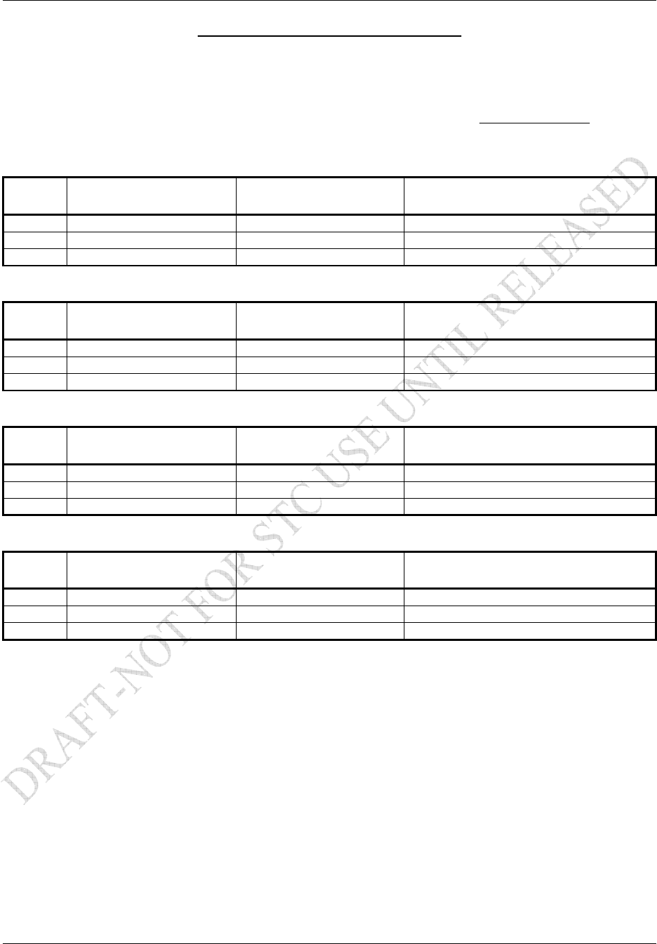
HARDWARE MOD LEVEL HISTORY
The following table identifies hardware modification (Mod) Levels. Mod Levels are listed with the
associated service bulletin number, service bulletin date, and the purpose of the modification. The table is
current at the time of publication of this manual (see date on front cover) and is subject to change without
notice. Authorized Garmin Sales and Service Centers are encouraged to access the most up-to-date
bulletin and advisory information on the Garmin Dealer Resource web site at www.garmin.com using
their Garmin-provided user name and password.
GDL 69/69A Mod Level History
Mod
Level Service Bulletin No. Service Bulletin Date Purpose Of Modification
1 - - - - - - - - Mod 1 unit identical to no mod unit
GRC 10 Mod Level History
Mod
Level Service Bulletin No. Service Bulletin Date Purpose Of Modification
GRT 10 Mod Level History
Mod
Level Service Bulletin No. Service Bulletin Date Purpose Of Modification
GRC 10 Mod Level History
Mod
Level Service Bulletin No. Service Bulletin Date Purpose Of Modification