Garmin 01178 Remote Control User Manual 190 00355 02 0F
Garmin International Inc Remote Control 190 00355 02 0F
Garmin >
Contents
Install Manual Sect 2
Installation Procedure
GDL 69/69A Installation Manual Page 2-1
190-00355-02 Revision F
2 INSTALLATION
2.1 Introduction
This section provides hardware equipment information for installing the GDL 69/69A and optional GRT
10, cabling for the XM antenna (GA 37, GA 55, GA 55A, or GA 57), and related hardware. Installation
of the GDL 69/69A and GRT 10 should follow the aircraft TC or STC requirements. For interconnects
with the GDU 104x, MX20 MFD, GMX 200 MFD, 400W/500W series or 400/500 series refer to
Appendix D of this manual. For installation information on the GDU 104x, MX20 MFD, GMX 200
MFD, 400W/500W series or 400/500 series, refer to their installation manuals.
Installation of the XM antennas is covered under separate Garmin GA Antenna AML STC number
SA01695SE.
2.2 Pre-Installation Information
Always follow acceptable avionics installation practices per FAA Advisory Circulars (AC) 43.13-1B,
43.13-2A, or later FAA approved revisions of these documents.
Follow the installation procedure in this manual as it is presented for a successful installation. Read the
entire manual before beginning the procedure. Prior to installation, consider the structural integrity of the
GDL 69/69A and GRT 10 installation as defined in AC 43.13-2A, Chapter 1 and evaluate the necessity
for audio suppression inputs in accordance with the GDL 69A Audio Limitations in Section 6. Perform
the post installation checkout before closing the work area in case problems occur.
Complete an electrical load analysis in accordance with AC 43.13-1B, Chapter 11, on the aircraft prior to
starting modification to ensure aircraft has the ability to carry the GDL 69/69A and GRT 10 load. Refer to
Section 2.8 for the power consumption of the GDL 69/69A and the GRT 10. Document the results of the
electrical load analysis on FAA Form 337.
2.3 Installation Materials
Configurations Available
The GDL 69, GDL 69A, and GRT 10/GRC 10 wireless remote system can be ordered in different kits,
each of which may contain components listed in the following table.
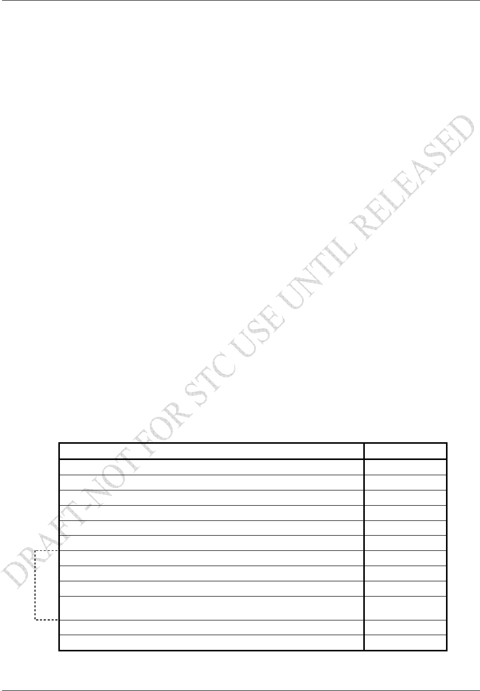
Table 2-1. GDL 69/69A Kit Contents
Description Part Number
GDL 69 XM Weather Data Receiver 011-00986-00
GDL 69A XM Weather/Audio Data Receiver 011-00987-00
Back Plate Assembly 011-00796-35
Remote Mount Rack GDL 69 115-00658-00
Connector Kit Assembly 011-00997-00
Configuration Module Assembly 011-00979-00
GA 37 XM and GPS Antenna 013-00245-00
GA 55 XM Antenna 011-01033-00
GA 55A XM Antenna 011-01153-00
OR
GA 57 XM and GPS Antenna (Not recommended for new
installations) 011-01032-00
Rack Nut Plate, 2 POS 011-00915-00
Modular Rack 115-00411-00
Installation Procedure
Page 2-2 GDL 69/69A Installation Manual
Rev. F 190-00355-02
Table 2-2. GRT 10 Transceiver Kit Contents
Description Part Number
GRT 10 (Wireless Transceiver) 011-01557-00
Connector Kit 011-01556-00
Table 2-3. GRC 10 Remote Control Kit Contents
Description Part Number
GRC 10 (Wireless Remote Control) 011-01558-00
Two AA Batteries 360-00004-00
GRC 10 User’s Guide 190-00355-11
Equipment Required But Not Supplied
Hardware for the GDL 69/69A:
Wire: MIL-W-22759/16 or equivalent
Shielded Wire: MIL-C-27500 or equivalent
Hardware for Remote Mount Rack:
Vertical Mount: Four #8-32 Pan Head Screws (MS35206, AN526 or equivalent)
Horizontal Mount: Four #6-32 x 100° Counter-Sunk Flat Head Screw (MS24693, AN507R or
equivalent)
Circuit Breaker: Appropriate for selected wire size
Hardware for GRT 10 Transceiver:
Four #6-32 Pan Head Screws (MS35206, AN526 or equivalent)
Installation Procedure
GDL 69/69A Installation Manual Page 2-3
190-00355-02 Rev. F
2.4 Equipment Mounting
Rack Location and Installation
The GDL 69/69A and optional GRT 10 may be mounted in a pressurized or unpressurized location,
neither unit requires forced-air cooling. When mounting, avoid locating the equipment near sources that
produce high levels of heat. The GDL 69/69A has two mounting rack options available, the remote rack
and the modular rack for use with the G1000 system.
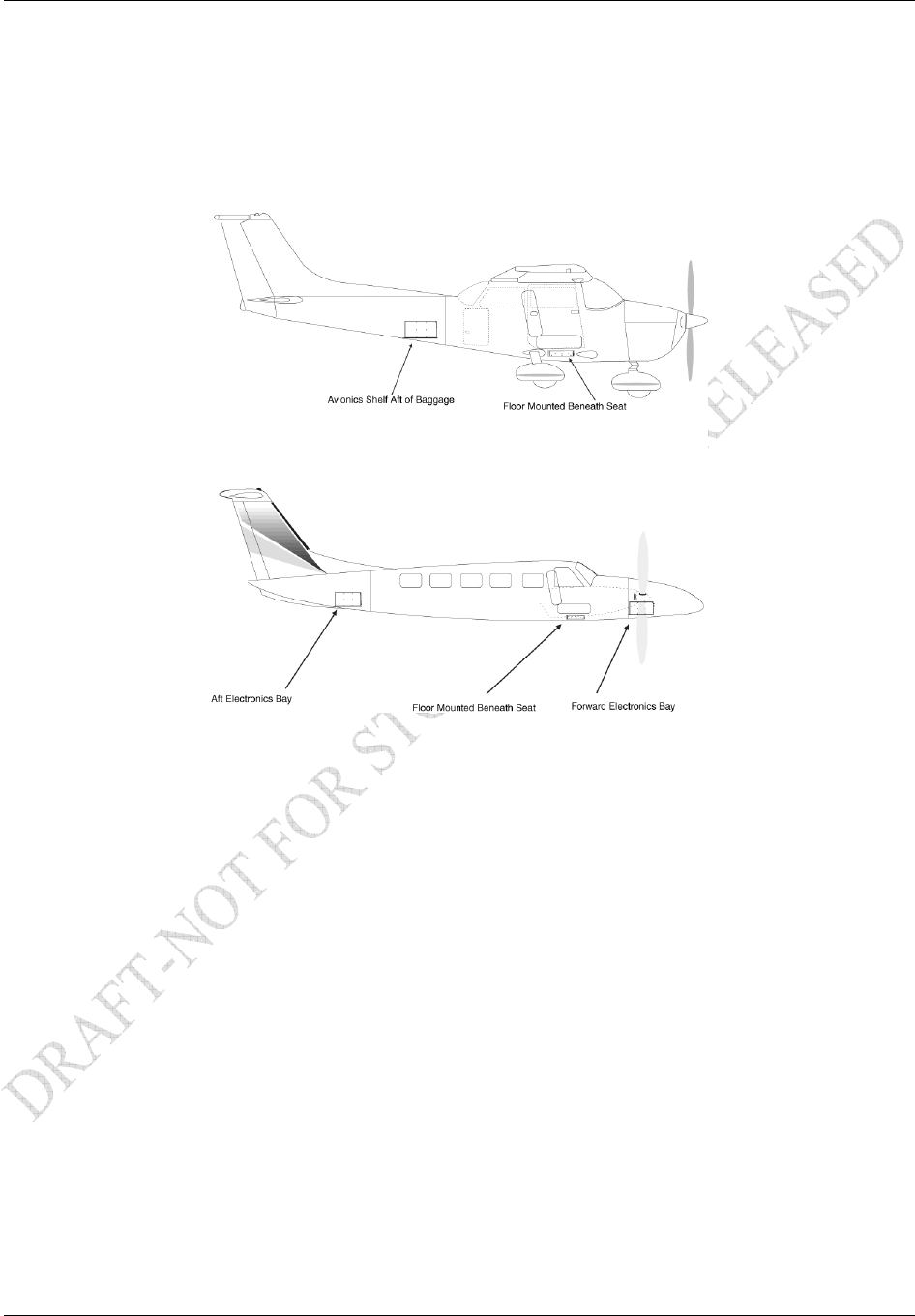
Figure 2-1. Suggested Mounting Locations for Remote Rack
Remote Mount Rack
The remote mount rack can be installed in a variety of locations, such as the electronics bay, behind the
instrument panel, under the seat or behind the rear baggage area. Leave sufficient clearance between the
GDL 69/69A and any obstruction. Install the rack in accordance with AC43.13-2A Chapter 2 Radio
Installations. The remote mount rack should be mounted to a surface known to have sufficient structural
integrity to withstand additional inertial forces imposed by a 1.86 pound unit (1.72 lbs. for GDL 69). If it
is necessary to build a shelf or bracket to mount the GDL 69/69A rack or if is not certain that the chosen
location is of sufficient structural integrity, refer to Appendix C. Refer to Figure 1-4 for the GDL 69/69A
remote mount rack dimensions. The rack can be mounted vertically using four 8-32 pan head screws
(MS35206, AN526 or equivalent.) It can also be mounted horizontally using four 6-32 100° counter-sunk
flathead screws (MS24693, AN507R or equivalent.) Ensure that the rack has a ground path to the
airframe by having at least one mounting screw in contact with the airframe to minimize radiated
electromagnetic interference (EMI).
Installation Procedure
Page 2-4 GDL 69/69A Installation Manual
Rev. F 190-00355-02
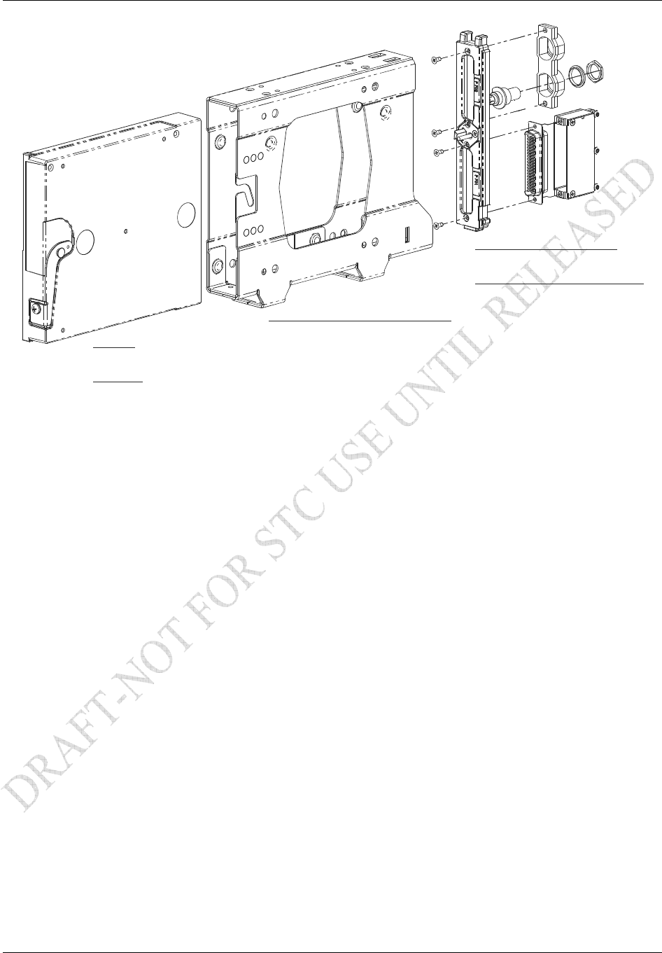
GDL 69
P/N: 011-00986-00
P/N: 011-00987-00
GDL 69A
BACK PLATE ASSEMBLY
P/N: 011-00796-35
CONNECTOR KIT ASSEMBLY
P/N: 011-00997-00
GDL 69 REMOTE MOUNT RACK
P/N: 115-00658-00
Figure 2-2. GDL 69/69A Remote Mount Rack
G1000 Modular Rack
The G1000 modular rack is used to install the GDL 69/69A in the standard G1000 integrated avionics
system rack. This modular rack may be mounted behind the instrument panel or in the avionics bay. Refer
to Figure 1-5 for the GDL 69/69A G1000 modular rack dimensions. This STC covers the installation of
the GDL 69/69A modular rack into the installed G1000 integrated avionics system rack, but does not
cover the installation of the G1000 integrated avionics system rack.
Installation Procedure
GDL 69/69A Installation Manual Page 2-5
190-00355-02 Rev. F
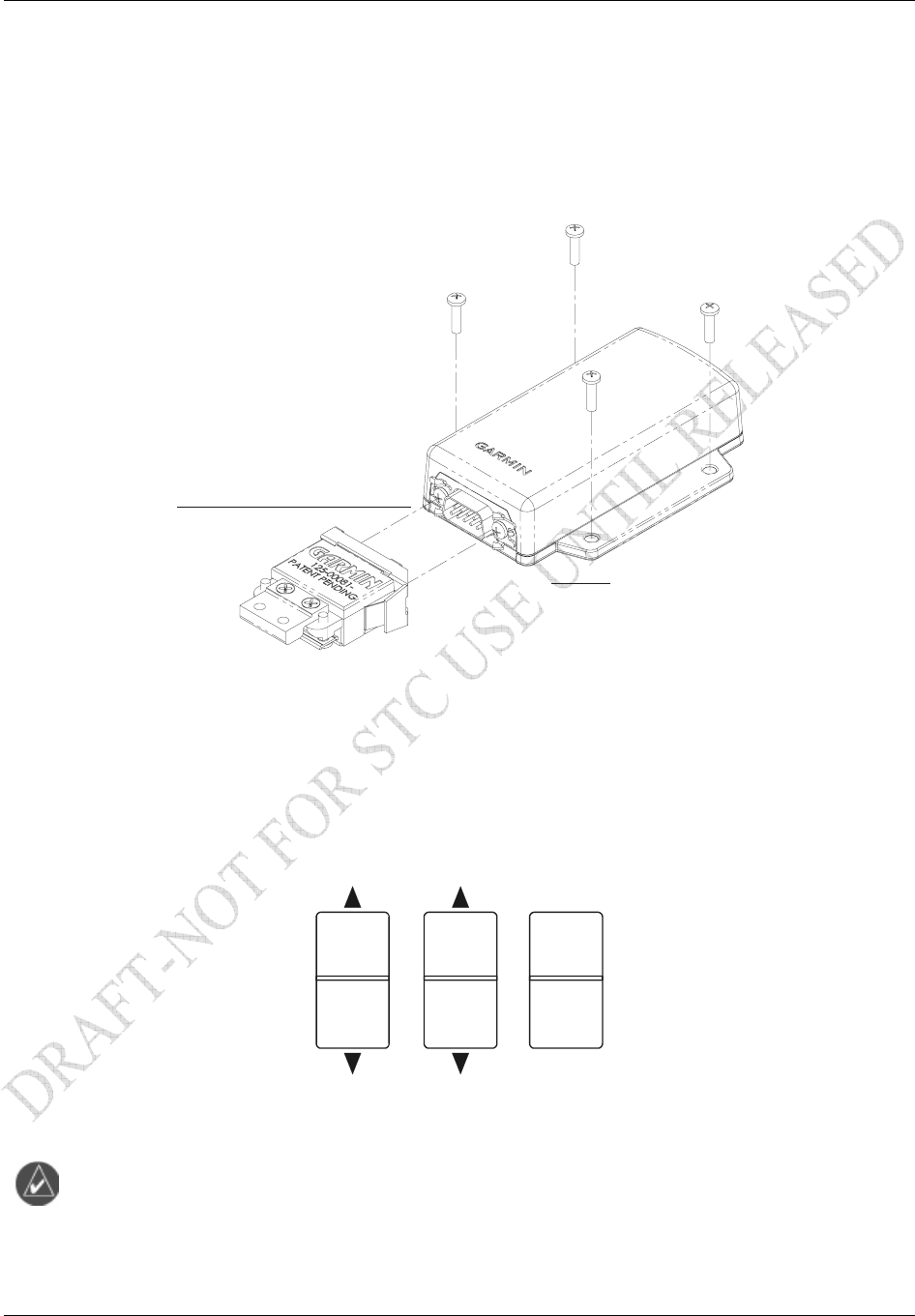
GRT 10 Mounting
The optional GRT 10 transceiver is mounted using four #6 pan head screws (MS35206, AN526, or
equivalent) onto a solid surface. Install the GRT 10 in accordance with AC43.13-2A Chapter 2 Radio
Installations. Because the weight of the GRT 10 is only 0.27 lbs, the impact of the weight to the
surrounding structure is negligible and no structural validation procedures are required. If the GDL 69A
is mounted behind a metal bulkhead, the GRT 10 should be mounted inside the cabin to get better signal
strength. For optimal performance, the end of the GRT 10 opposite the 9-pin D-sub should face the cabin.
CONNECTOR KIT ASSEMBLY
P/N: 011-01556-00
GRT 10
P/N: 011-01557-00
Figure 2-3. GRT 10 Mounting
Remote Switches
Installation of rocker switches should be made on a flat surface and located at a convenient location
within the cabin. Each rocker switch installed must be properly marked of its function. Use of rocker
switches vs. toggle switches will prevent the possibility of raising and lowering the volume at the same
time or raising and lowering the channels at the same time. Wire used for discrete switches should be 24
AWG (MIL Spec M22759) and should be routed as appropriate, avoiding kinking or sharp bends. Figure
2-4 shows typical rocker switches.
Channel
V
olume Mute
Figure 2-4. Typical Rocker Switches
NOTE
Remote switches can be installed even if a GRT 10 is installed.
Installation Procedure
Page 2-6 GDL 69/69A Installation Manual
Rev. F 190-00355-02
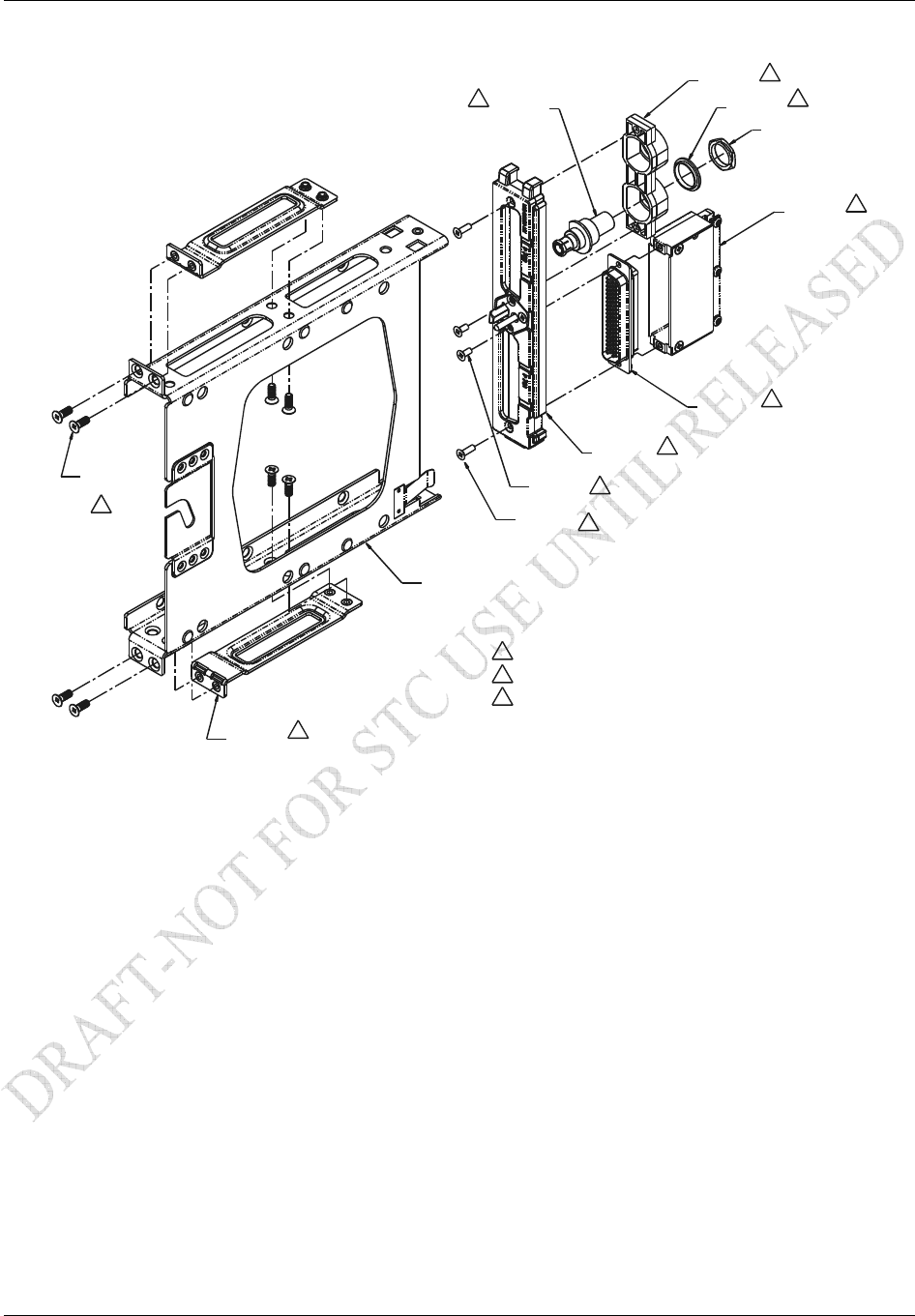
2
MAY ALTERNATELY USE P/N 115-00511-00
(PART OF KIT 011-01148-00)
011-00950-04
330-00185-78
211-63207-10
8 PLCS
2 PLCS
115-00657-00
4. APPLY THREAD LOCKING COMPOUND TO ALL THREADED FASTENERS.
2. PART OF 011-00915-00 NUT PLATE KIT
1. PART OF 011-00796-35 BACK PLATE ASSEMBLY
NOTES:
115-00411-00
125-00059-04
2
1
211-63234-12
212-00022-00
125-00097-00
330-00053-02
1
1
1
PART OF 330-00053-02
3
3
1
211-63234-10
3. PART OF 011-00997-00 CONNECTOR KIT
3 PLCS
3
2 PLCS
Figure 2-5. Modular Rack for the G1000
Installation Procedure
GDL 69/69A Installation Manual Page 2-7
190-00355-02 Rev. F
2.5 Cabling and Wiring
Wiring should be installed in accordance with AC 43.13-1B Chapter 11. When wire separation cannot be
achieved, the following issues should be addressed:
The cable harness should not be located near flight control cables and control, high electrical
capacity lines or fuel lines
The cable harness should be located in a protected area of the aircraft
Do not route cable near high-energy sources
Refer to the interconnection diagrams in Appendix D for the appropriate wiring. Once the cable
assemblies have been made, attach the cable connector to the rear of the rack. Route the wiring bundle as
appropriate. Avoid sharp bends.
For the GDL 69/69A use 22 or 24 AWG wire for all connections except for power. Use 22 AWG for
power/ground. For the GRT 10 use 22 AWG wire for all connections including power/ground.
After the GDL 69/69A cable assemblies are made assemble the backshell as shown in Figure 2-7. Then
install the backshell connector to the rear plate using the screws provided in the connector kit. After the
rack is installed, assemble the rear plate into the rack.
Wiring Harness
Allow adequate space for installation of cables and connectors. The installer supplies and fabricates all of
the cables. Except for the antenna connection, all electrical connections are made through a 78-pin D-sub
(GDL 69/69A) and 9-pin D-sub (GRT 10) connectors provided by Garmin. Construct the wiring harness
according to the information contained in this and the following sections. Cable lengths will vary
depending upon installation. Strip all wires going to the D-sub connectors 1/8”. Insert the wire into the
pin and crimp with one of the recommended (or equivalent) crimping tools. Insert the pin into the D-sub
connector housing locations as specified by the interconnect drawing in Appendix D. Verify the pin is
properly engaged into the connector by gently tugging on the wire. Route and secure the cable run from
the GDL 69/69A and GRT 10 to the other units away from sources of electrical noise.
Section 3 defines the electrical characteristics of all input and output signals. Required connectors and
associated hardware are supplied with the connector kit. See Appendix D for interconnect wiring
diagrams.
CAUTION
Check wiring connections for errors before inserting the GDL 69/69A into the rack or
mounting bracket or connecting the 9-pin D-sub to the GRT 10. Incorrect wiring could
cause component damage.
Table 2-4. Pin Contact Part Numbers
Wire Gauge 78-pin connectors
22-28 AWG
9-pin connectors
20-24 AWG
Garmin P/N 336-00021-00 336-00022-00
Military P/N M39029/58-360 M39029/63-368
AMP 204370-2 205090-1
Positronic MC8522D M39029/63-368
ITT Cannon 030-2042-000 031-1007-42

Installation Procedure
Page 2-8 GDL 69/69A Installation Manual
Rev. F 190-00355-02
Table 2-5. Recommended Crimp Tools
20-24 AWG
Wire Gauge Hand Crimping Tool Positioner Insertion/
Extraction Tool
Military P/N M22520/2-01 M22520/2-09 M81969/1-04
Positronic 9507 9502-3 M81969/1-04
ITT Cannon 995-0001-584 995-0001-739 N/A
AMP 601966-1 601966-6 91067-1
Daniels AFM8 K42 M81969/1-04
Astro 615717 615725 M81969/1-04
NOTE
Insertion/extraction tools from ITT Cannon are all plastic; others are plastic with metal
tip. Non-Garmin part numbers shown are not maintained by Garmin and are subject to
change without notice.
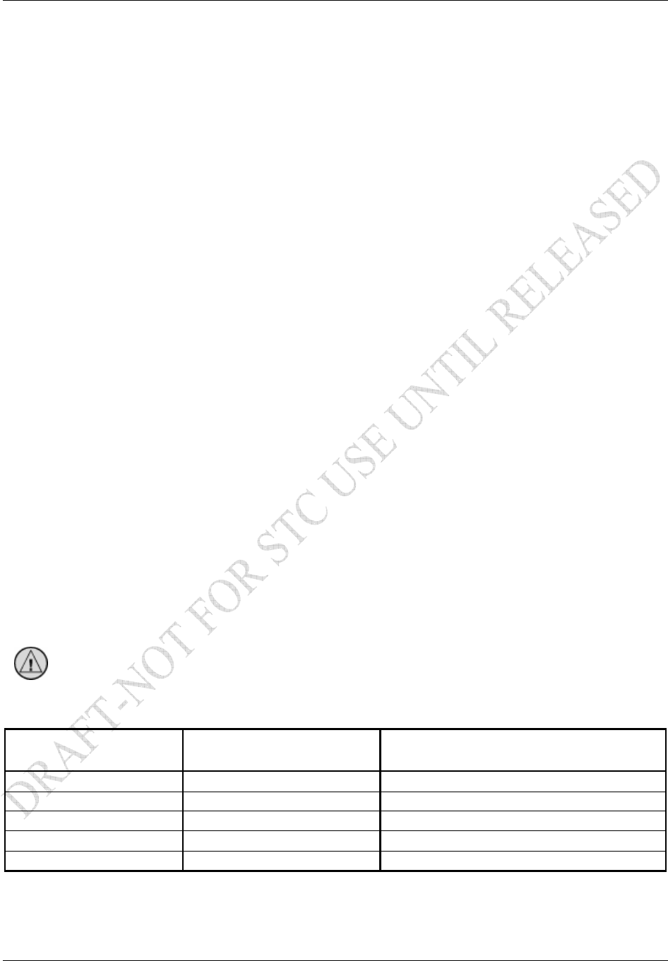
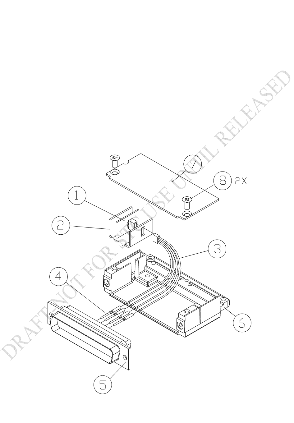
GDL 69/69A Backshell Assembly and D-Sub Connector
2.5.2.1 GDL 69/69A Connector Assembly
1. Backshell Cast Housing: Provides a mounting point for all other connector accessories.
2. Configuration Module: Installation details provided in Section 2.5.2.2.
3. D-sub Connector: Installation details provided in Section 2.5.2.2.
4. Spider Ground System: Allows shield grounds to be made to the backshell housing. Installation
details provided in Section 2.5.2.5.
5. Strain Relief Tab: Provides strength and support to wiring bundles.
6. Backshell Lid: Provides easy access when servicing connector.
Installation Procedure
GDL 69/69A Installation Manual Page 2-9
190-00355-02 Rev. F
Table 2-6. GDL 69/69A Connector Assembly
Item Number (Reference
Figure 2-6) Description Qty
Garmin Part
Number
1 Backshell, with Config 50/78 Pin 1 125-00085-00
2 PCB Assembly, Configuration Module 1 012-00605-00
3 Connector, High Density, 78 Pin 1 330-00185-78
4 Wire Harness, Backshell Ground 1 320-00212-00
5 Clamp, Backshell, 62/78 Pin 1 115-00499-03
6 Cover, Backshell, 50/78 Pin 1 115-00500-04
7 Screw, 4-40 x .187 FLHP100, Stainless Steel 2 211-63234-06
8 Screw, 4-40 x .375, Phillips, Stainless Steel 3 211-60234-10
9 Screw, 4-40 x .250, FLHP, Stainless Steel 2 211-63234-08
76
5
4
8
2
1
3
9
Figure 2-6. Garmin Connector Assembly
Installation Procedure
Page 2-10 GDL 69/69A Installation Manual
Rev. F 190-00355-02
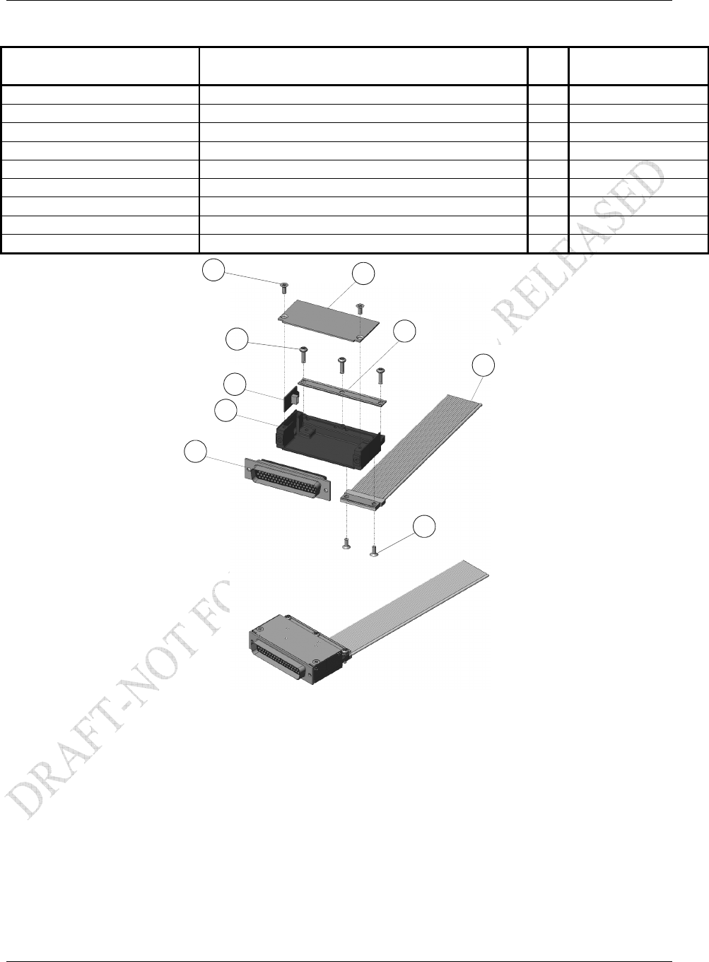
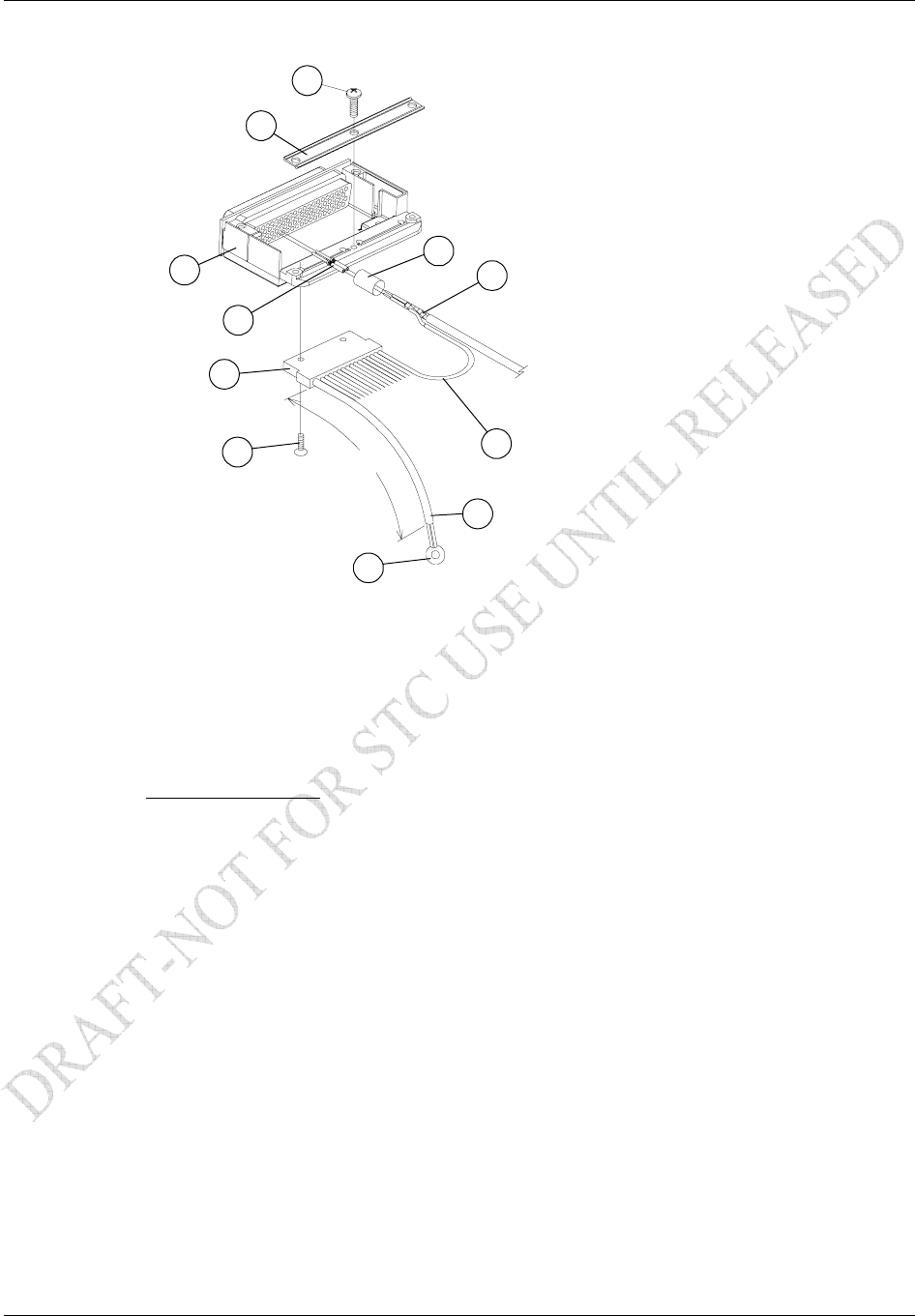
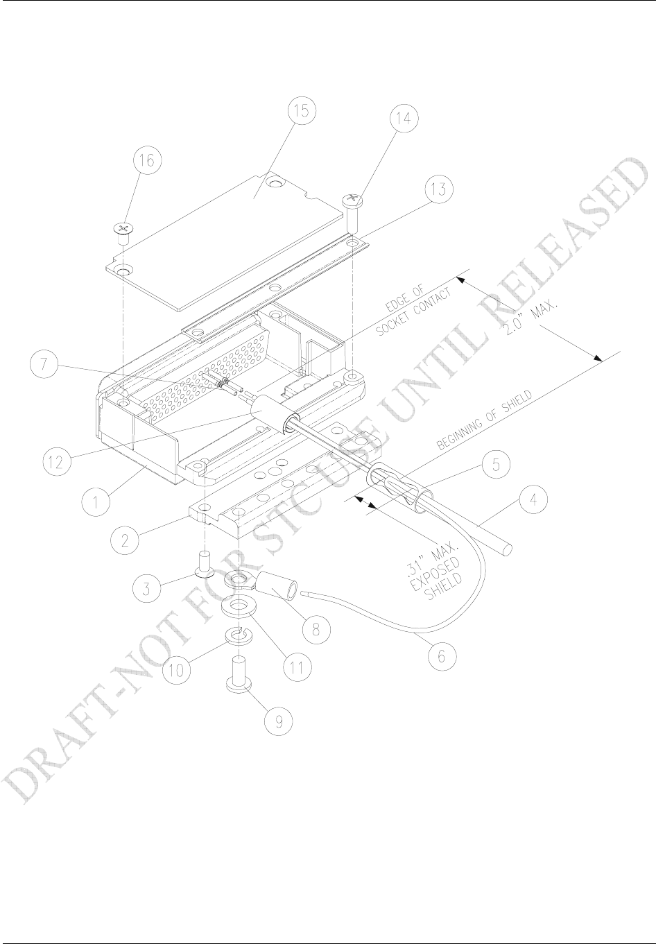
2.5.2.2 Configuration Module Installation for GDL 69/69A
The GDL 69/69A connector kit includes one Garmin backshell assembly. The backshell assembly houses
the configuration module. Garmin’s backshell also gives the installer the ability to easily terminate shield
grounds at the backshell housing using the Spider grounding kit. Refer to Figure 2-7 for details and item
numbers referenced below.
1. Crimp pins (4) onto each wire of the four-conductor wire harness (3). Strip 1/8” of insulation
from each wire prior to crimping.
2. Insert newly crimped pins and wires (3, 4) into the appropriate connector housing (5) location as
specified by the interconnect drawings in Appendix D.
3. Apply the spacer (2) by wrapping it around the PCB Board (1) making sure to insert the plastic
connector mounted on the board into the provided hole of the spacer.
4. Plug the four-conductor wire harness (3) into the connector on the PCB Board (1).
5. Insert into the backshell (6) recess, PCB Board (1) with pad (2) in position.
6. Attach cover (7) to backshell (6) using screws (8).
Figure 2-7. Backshell Assembly
Installation Procedure
GDL 69/69A Installation Manual Page 2-11
190-00355-02 Rev. F
2.5.2.3 Spider Grounding Installation for GDL 69/69A
The Spider Grounding Kit, part of the connector kit, allows shielded cables that go to a backshell to be
terminated to the backshell. Twenty AWG #24 wires are available to splice with the cable shields. The
wires all terminate to a terminal that is fastened to the backshell. A single AWG #16 wire provides
ground reference to the terminal, thereby grounding all Spider leads to the aircraft.
Spider Kit terminals are screwed to the backshell using the tapped holes provided.
Table 2-7. Spider Kits
Reference
Figure 2-7 Description Qty. Included Garmin Part Number
Spider Kit w/ 21 Conductors: 011-00980-00 (Included in 011-00997-00)
2 Wire Harness, Backshell Ground, 21 Conductor
3 1 Conductor, 24”, AWG #16
4 20 Conductor, 6”, AWG #24
1 320-00212-00
5 Screw, 4-40 x .250, FLHP 100°, SS/P, Nylon 2 211-63234-08
2.5.2.4 Spider Parts List
The following table provides a list of parts needed to install a Spider kit. Most parts for this installation
are included in the Spider installation kits shown in Table 2-7. Some are to be provided by the installer.
The following tables show the list of required parts as well as callouts for the drawings shown in Figure
2-8.
Table 2-8. Spider Installation Required Parts
Reference
Figure 2-8 Description Qty.
Included Garmin Part Number/MIL Spec
1 Cast Housing from Garmin Backshell
Kit 0 011-00950-( )
2, 3, 4, 5 Spider Kit 1
011-00980-00
or
011-00980-01
6 Shield Termination
(method optional, see Step 3 below) 0 Parts used depend on method chosen
7 Multiple-Conductor Shielded Cable
(2 –conductor demonstrated here) 0 Reference Interconnect Diagrams
8 Pins 0 336-00021-00
9 Ring Terminal 0 MS25036-152
10 Strain Relief from Garmin Backshell Kit 0 011-00950-( )
11 Screw, 4-40x.375, PHP, SS/P, w/NYL 0 211-60234-10
Installation Procedure
Page 2-12 GDL 69/69A Installation Manual
Rev. F 190-00355-02
2.5.2.5 Spider and Connector Assembly Procedure
24 AWG
TO GROUND
(AIRFRAME OR
TAB ON RACK)
16 AWG
24”
1
2
3
4
5
6
7
8
9
10
11
2x
2x
3x
Figure 2-8. Spider Installation Drawing
1. At one end of the shielded cable (7), strip back 2.0” to 3.5” of jacket while retaining the shield.
Trim away enough to leave 0.5” of shield exposed.
2. Strip 1/8” of insulation from one of the AWG #24 wires (4) on the Spider.
3. Connect the prepared AWG #24 Spider wire (4) to the shield (7) using an approved shield
termination technique.
Installation Options:
a) Slide a solder sleeve (6) onto the prepared wire assembly (4, 7) and shrink with a heat
gun. The size of solder sleeve must accommodate the number of conductors present
in the cable. Reference the following MIL-Specs for solder sleeves (M83519/1-1,
M83519/1-2, M83519/1-3, M83519/1-4, M83519/1-5).
b) Solder the prepared wire assembly (4, 7). Slide a piece of shrink tube (6) onto the
prepared wire assembly and shrink using a heat gun. The size of shrink tube must
accommodate the number of conductors present in the cable.
4. Strip 1/8” of insulation from the shielded cable end and crimp a pin (8) to each of the conductors
(7).
5. Insert crimped pins and wires (7, 8) into the appropriate housing location as specified by the
installation wiring diagrams.
6. Repeat steps 1 through 3 as needed for the remaining shielded cables (7). Use only one Spider
wire (4) per shield. Remaining AWG #24 wires should be tied back and dressed with shrink
tubing.
7. Wrap the cable bundle with Silicone Fusion Tape (Garmin P/N: 249-00114-00 or a similar
version) at the point where the backshell strain relief (10) and cast housing (1) contacts the cable
bundle. Separation of the bundle into two smaller bundles, wrapped individually, may make
installation of the strain relief easier.
8. Place the smooth side of the backshell strain relief (10) across the cable bundle and secure using
the three screws (11).

Installation Procedure
GDL 69/69A Installation Manual Page 2-13
190-00355-02 Rev. F
WARNING
Placing the strain relief grooved side across the cable bundle may cause damage to wires.
9. Attach the Spider terminal (2) to the backshell (1) by inserting the two screws (5) into the tapped
holes on the backshell (1).
10. Attach a ring terminal (9) to the AWG #16 wire (3) length 24” and terminate to ground. The
ground connection can be made using either the closest aircraft ground or with tabs on racks.
Trimming of this wire to the shortest practical length before attaching the ring terminal is
recommended to reduce the effects of noise and interference. Do not extend this wire’s length.
Installation Procedure
Page 2-14 GDL 69/69A Installation Manual
Rev. F 190-00355-02
GRT 10 Backshell Assembly and D-sub Connector
2.5.3.1 GRT 10 Connector Assembly
1. Backshell Cast Housing: Provides a mounting point for all other connector accessories.
2. D-sub Connector: Installation details provided in Section 2.4.4.
3. Shield Block Ground Kit: Allows shield grounds to be made to the backshell housing. Installation
details provided in Section 2.5.3.3.
4. Strain Relief Tab: Provides strength and support to wiring bundles.
5. Backshell Lid: Provides easy access when servicing connector.
Table 2-9. GRT 10 Backshell Assembly
Reference
Figure 2-9
Description Garmin P/N Notes
1 Cast Housing (From Garmin Backshell Kit) 125-00081-00 [2]
2 Shield block 117-00147-00 [3]
3 Screw, 4-40 x.250, FLHP100, SS/P, Nylon 211-63234-08 [3]
4 Multiple Conductor Shielded Cable
(See Interconnect Diagrams, Appendix D
As Required [4]
5 Shield Terminator As Required [4], [5]
6 Wire, Insulated (20 – 22 AWG) As Required [4], [5]
7 Socket Contacts 336-00022-00 [1]
8 Ring terminal, #8, insulated, 18-22 AWG, 14-16 AWG MS25036-149,
MS25036-153,
MS25036-156
[4]
9 Screw, PHP, 8-32x.312", Stainless or Cad Plated Steel MS51957-42,
MS35206-242
[4]
10 Split Washer, #8, (.045" compressed thickness) Stainless
or Cad-plated steel
MS35338-137,
MS35338-42
[4]
11 Flat Washer, #8, .032" thick, .174"ID, .375" OD, Stainless
or Cad Plated Steel
NAS1149CN832R,
NAS1149FN832P
[4]
12 Silicon Fusion Tape 249-00114-00 [4]
13 Strain Relief 115-00499-00 [2]
14 Screw,4-40x.375, PHP, SS/P, with Nylon 211-60234-10 [2]
15 Cover 115-00500-00 [2]
16 Screw, 4-40x.187, FLHP100, SS/P, with Nylon 211-63234-06 [2]
[1] Supplied as part of GRT 10 Connector Kit P/N 011-01556-00.
[2] Supplied as part of Backshell Kit P/N 011-00950-00 (included in kit 011-01556-00).
[3] Supplied as part of Ground Adapter Kit P/N 011-01169-00 (included in kit 011-01556-00).
[4] Not supplied – must be purchased separately.
[5] Solder sleeve with pre-installed lead may be used instead of items 5 and 6.
Installation Procedure
GDL 69/69A Installation Manual Page 2-15
190-00355-02 Rev. F
2.5.3.2 D-Sub Connector and Mounting Hardware
Table 2-10. D-Sub Connector and Hardware
Item Description Garmin P/N Notes
9-Pin Housing (Female) D-Sub, Standard Density, Mil Crimp, 9 ckt 330-00383-09 [1], [2]
Spring-loaded Slidelock D-Sub, Slide Lock Kit, 9/15 Pin 330-90006-00 [1]
Screw Screw, 4-40 x .375, PHP, SS/P, Nylon 211-60234-10 [1]
[1] Supplied as part of the GRT 10 Connector Kit P/N 011-01556-00.
[2] Tabless backshell (330-00383-09) is required for use with the slidelock mount
CAUTION
When mounting the slidelock, use only the specified screws (211-60234-10). Do not
attempt to use self-tapping screws, as these damage the backshell housing.
Installation Procedure
Page 2-16 GDL 69/69A Installation Manual
Rev. F 190-00355-02
2.5.3.3 Shield Block Assembly Procedure
The parts for the connector and backshell assembly for GRT 10 installations are listed in Table 2-9 and
shown in Figure 2-9.
Figure 2-9. Typical Shield Block Install onto Backshell Connector Assembly
Installation Procedure
GDL 69/69A Installation Manual Page 2-17
190-00355-02 Rev. F
1. Attach the Shield Block (2) to the backshell (1) by inserting the flathead screws (3) through the holes
on the Shield Block and threading into the tapped holes on the backshell (1). (See Figure 2-9).
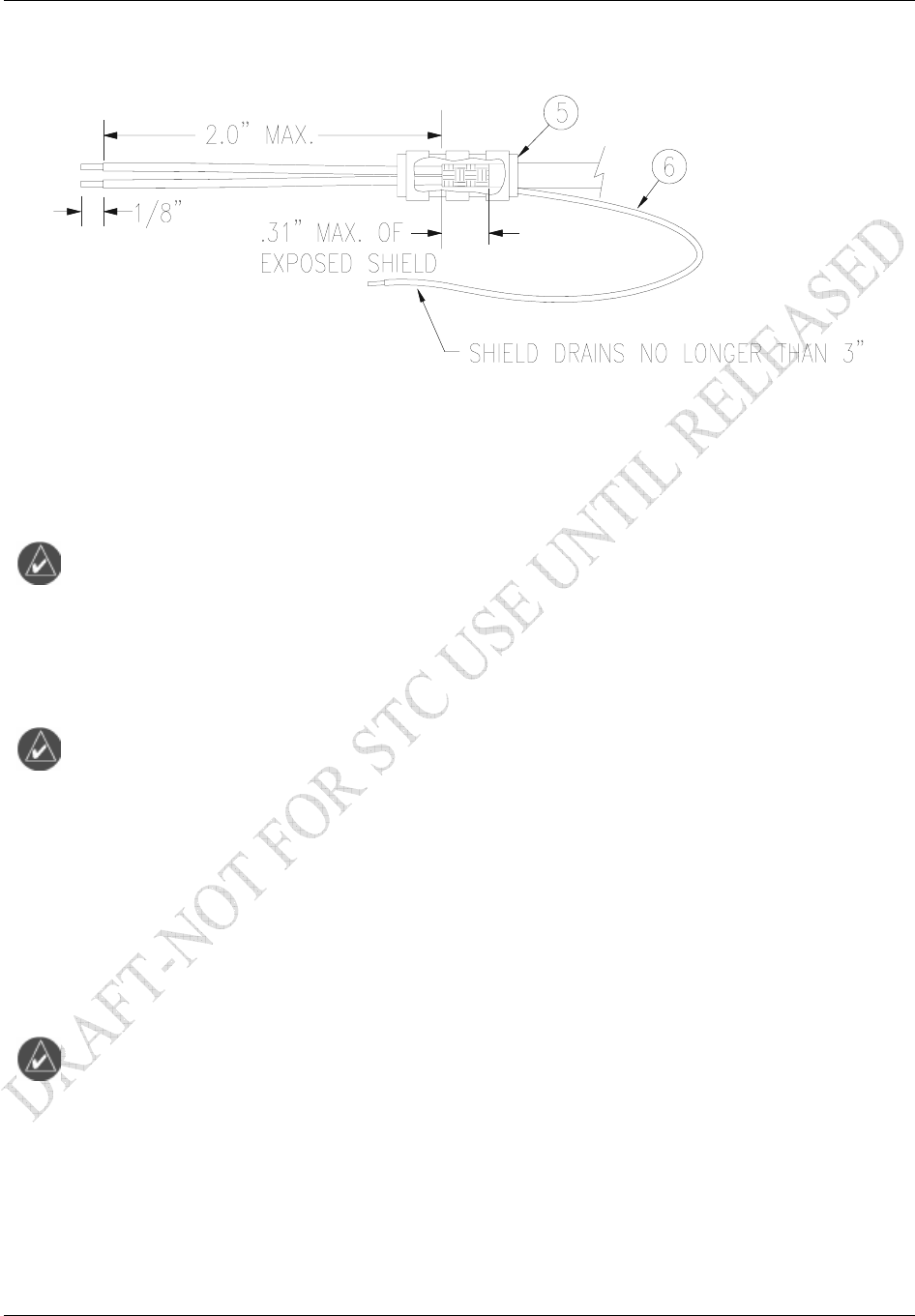
Figure 2-10. Shielded Cable Preparation
2. At the end of the shielded cable (4), strip back a 2” maximum length of the jacket to expose the braid.
Remove this exposed braid. Carefully score the jacket 1/4” to 5/16” from the end and remove the
jacket to leave the braid exposed.
NOTE
Solder sleeves with pre-installed shield drains may be used instead of separate shield
terminators and individual wires.
3. Connect a 20 or 22 AWG wire (6) to the exposed shield of the prepared cable assembly. (See Figure
2-10). Note: AC 43.13 may be a helpful reference for termination techniques.
NOTE
Solder Sleeves with pre-installed lead: A preferred solder sleeve is the Raychem S03
Series with the thermochromic temperature indicator. These solder sleeves come with a
pre-installed lead and effectively take the place of items 5 and 6. For detailed
instructions on product use, refer to Raychem installation procedure.
4. Slide a shield terminator (5) onto the prepared cable assembly (4) and connect the wire (6) to the
shield using a heat gun approved for use with solder sleeves. The chosen size of solder sleeve must
accommodate both the number of conductors present in the cable and the wire (6) to be attached.
5. Repeat steps 2 through 4 as needed for the remaining shielded cables.
NOTE
Each tapped hole on the Shield Block (2) may accommodate only two ring terminals (8).
It is preferred that a maximum of two Wires (6) be terminated per ring terminal. Two
Wires per ring terminal will necessitate the use of a Ring terminal, #8, insulated, 14-16
AWG (MS25036-153). If only a single Wire is left or if only a single Wire is need for
this connector a Ring terminal, #8, insulated, 18-22 AWG (MS25036-149) can
accommodate this single wire. If more wires exist for the connector than two per ring
terminal, it is permissible to terminate three wires per ring terminal.
6. Terminate the ring terminals to the Shield Block (2) by placing items on the Pan Head Screw (9) in
the following order: Split Washer (10), Flat Washer (11), first Ring Terminal, second Ring Terminal
if needed, before finally inserting the screw into the tapped holes on the Shield Block.
7. Wrap the cable bundle with Silicone Fusion Tape (12) (GPN: 249-00114-00 or a similar version) at
the point where the backshell strain relief and cast housing will contact the cable bundle.

Installation Procedure
Page 2-18 GDL 69/69A Installation Manual
Rev. F 190-00355-02
8. Place the smooth side of the backshell strain relief (13) across the cable bundle and secure using the
three screws (14).
WARNING
Placing the grooved side of the strain relief across the cable bundle may damage wires.
9. Attach the cover (15) to the backshell (1) using two screws (16).
Audio Suppression
XM Audio Entertainment to crew locations may require audio suppression to comply with the STC
Limitations. Determine the activation state for each horn installed in the aircraft (aircraft power
signifying active high or ground signifying active low) by using one of the following methods:
Find the horn and compare the installation with Figure D-5.
Activate the horn per the method described in the aircraft’s maintenance manual. (For the gear
horn, this may require having the aircraft raised on jacks).
With a multimeter, determine which horn contact changes state with the activation signal and if
the active state is high or low.
Wire the appropriate audio suppression input (high or low) in accordance with Figure D-5.
Remote Discrete Switches (Optional)
If XM audio entertainment is installed in the aircraft, optional functional switches may be installed as
desired even if a GRT 10 is installed. The functions of the switches must include the ability to mute the
audio, adjust the volume and channels. It may be incorporated as desired depending on the installation.
Figure D-1 and Figure D-2 detail the wiring for the optional discrete switches. A common aircraft ground
signal may be used for each switch. It is recommended to use a rocker type switch for channel and
volume control. Using a rocker type switch will prevent inadvertently raising and lowering the channel at
the same time as well as the volume. An acceptable switch for this installation of the remote discrete
switches is Carlingswitch P/N 62111281-0-0-N (62111231-0-0-N for the switch used for muting). Since
the input signals are active-low it is permissible to use multiple switches for each function. This would
allow volume and channel control to be available at each passenger station.
The GDL 69/69A’s 15 preset channels (favorites) can be sequenced using the audio channel control input.
On power up, the GDL 69A reads the state of the audio channel control input. When this discrete is
active (low), the Channel Up and Channel Down inputs will function as Preset Up and Preset Down,
respectively.

Installation Procedure
GDL 69/69A Installation Manual Page 2-19
190-00355-02 Rev. F
2.6 XM Antenna
For use with the GDL 69/69A, the GA 37, GA 55, GA 55A, and GA 57 antennas are an XM Satellite
Radio antenna operating within a frequency range of 2332-2345 MHz for general aviation.
NOTE
Depending on specific installations, the installer may want to use a different make/model
of XM Satellite Radio antenna. (An alternate antenna may be used providing it meets the
minimum requirements shown in Table 1-10).
It is the installer’s responsibility to ensure that their choice of antenna meets FAA
certification standards according to the specific installation. This installation manual
discusses only the antennas listed in Table 1-9, which are used during STC certification
by Garmin. Other antennas may be acceptable but their installation is not covered by this
manual and is outside the scope of the data approved in the GDL 69/69A STC.
There are several critical factors to take into consideration before installing an antenna for a satellite
communications system. These factors are addressed in the following sections.
Antenna Mounting
For installation mounting of the XM antenna listed in Table 1-9, use Garmin GA Antenna AML STC
number SA01695SE. Verify aircraft model is listed on the AML and follow limitations defined in that
STC data.
Antenna Grounding
NOTE
Improper grounding of the antenna is typically the primary cause of reduced signal
reception quality.
It is very important to have good conductivity between the coaxial shield and the ground plane. This is
ensured when all the fasteners properly ground the antenna base to the skin of the aircraft. The resistance
between the antenna and the skin of the aircraft should be less than 10 milliohms.
Installation Procedure
Page 2-20 GDL 69/69A Installation Manual
Rev. F 190-00355-02
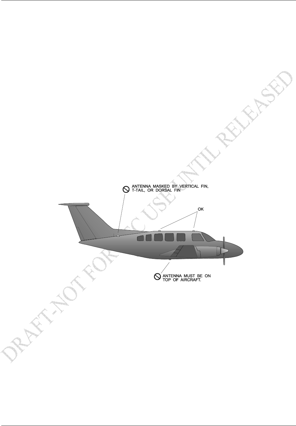
XM Antenna Location
As with any antenna installation, keep the following points in mind:
1. The XM Satellite signal is a line-of-sight signal. Locating antennas too close to obstructions such
as the vertical stabilizer will limit the reception of the satellite signal.
2. Maintain about three feet from heater, ignition, autopilot, and other control surface actuators and
motors. Maintain about five feet from fluorescent lamps, related ballast, air conditioners, blowers,
strobe lights and power supplies.
3. The minimum distances to be observed when selecting an antenna location are as follows:
1.25 inches from any passive (receive only) antenna such as a GPS or another XM.
5 inches from a VHF active antenna such as COM or ACARS.
5 inches from an active radar altimeter (4 GHz).
12 inches from a UHF / Microwave transmitting antenna such as a transponder, DME, active
TCAS, UAT, SATCOM, or Flitephone.
4. The XM antenna must be mounted on top of the aircraft for greatest satellite visibility. For best
performance, select a location with an unobstructed view of the sky above the aircraft when in
level flight. Location of communication antennas too close to the XM antenna may not only
degrade the transmission through reflection, but can also absorb and re-radiate the transmission
causing a condition similar to having two COM antennas located in close proximity to each other.
Figure 2-11. Antenna Installation Location
Installation Procedure
GDL 69/69A Installation Manual Page 2-21
190-00355-02 Rev. F
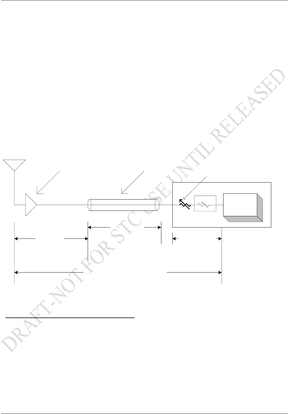
XM Radio Antenna to Receiver Signal Requirements
The XM Radio Receiver used in the GDL 69/69A has a system signal requirement of 20dB +/- 1dB gain
from the input of the antenna to the input of the XM receiver internal to the GDL 69/69A. To insure the
proper operation and optimum performance of the GDL 69/69A, the installation must meet the
requirements specified in Table 1-10, and the installer must account for the signal gain and loss factors
that exist between the antenna and the XM receiver. The gain/loss factors that need to be accounted for
are shown in Figure 2-12. The GDL 69/69A has the capability to internally adjust for variances in the
gain/loss factors by providing additional gain or loss within the range of +6dB to -4dB. If the GDL
69/69A gain/loss factor is outside this range, additional gain or loss must be added between the antenna
and the GDL 69/69A RF input. Record the gain/loss components in Table 2-11 and in the post-
installation checkout sheet located at the end of Section 4. The variable attenuation value required to
attain the GDL 69/69A gain/loss component will be programmed into the configuration module during
post installation checkout.
GDL69
XM Receiver
20dB Gain +/- 1dB
Factory Set
Antenna Gain Cable Loss 0-10dB
Variable Attenuator
GDL69 XM Antenna to Receiver
Signal Gain Requirements
GDL 69 Gain/Loss
+6dB to -4dB
Ant Gain
+25dB
Cable Loss
0 - 10dB
Factory default value for
cable loss is -4.5dB
(Based on12-14ft RG-400/U)
Factory default
setting for Gain/Loss
is -0.5dB
Signal Gain Equation
20dB +/- 1dB = Antenna Gain - Cable Loss (+/-) GDL 69 Internal Gain/Loss
Equation Values------------------------Range-------
Antenna Gain = 23dB to 40dB
Cable Loss = 0.5dB to 26dB
GDL 69 Internal Gain/Loss = +6dB to -4dB (Based on Variable Attenuator setting 0dB to 10dB)
Equation using GA 55, GA 55A, GA57 Antenna with 12-16ft RG-400/U cable (Factory Default setting)
25dB - 4.5dB - 0.5dB = 20dB
Figure 2-12. XM Signal Gain Requirements

Installation Procedure
Page 2-22 GDL 69/69A Installation Manual
Rev. F 190-00355-02
Table 2-11. XM Gain/Loss Component Calculation
Antenna Gain (1) +
Cable Loss (2) (3) -
GDL 69/69A Gain/Loss (4)
+6dB > x > -4dB +/-
Total Gain
Antenna/Receiver = 20 dB
Note:
(1) Garmin GA 37, GA 55, GA 55A, GA 57 XM antenna typical gain 25 dB. For antenna gain for other
antennas, see manufacturer’s specifications.
(2) If 12-16ft of RG-400/U cable is used, a value of 4.5dB can be used. See Section 2.6.4.1 for
explanation of calculation.
(3) If an antenna with increased gain is installed (antenna other than the Garmin antennas listed in
Table 1-9), additional cable length may be required to be coiled to compensate for the required
cable loss. Alternately, an external attenuator may be used to obtain the desired antenna cable loss.
However, installation of the external attenuator is beyond the scope of this STC. Additional
manufacturer’s data may be necessary and FAA approval may be required to cover the installation
of an external attenuator.
(4) The GDL 69/69A Gain/Loss component must be between +6dB and -4dB. If the GDL 69/69A
gain/loss component is outside this range, additional gain or loss must be added between the
antenna and the GDL 69/69A RF input. The factory default setting for the internal GDL 69/69A
component is -0.5dB. The variable attenuation value required to attain the GDL 69/69A gain/loss
component will be programmed into the configuration module during post installation checkout.
See Section 2.6.4.2 for explanation of calculation.
2.6.4.1 Determining Antenna Cable Loss Value
The GDL 69/69A is factory preset with a default cable loss value of 4.5 dB, which is equivalent to 12 to
16 feet of RG-400/U cable with two properly terminated TNC connectors. If the installed antenna cable is
within this length, use this value in Table 2-11. If the cable is different from the default cable, use the
following formula to determine the cable loss value to use in Table 2-11.
Loss in dB = (Length x Loss) + (0.5 x #Connectors)
100
Where:
Length – Cable length in feet
Loss – Specified cable loss per 100 feet at 2332-2345 MHz
Connectors – Number of connectors on cable
For example:
If an RG-400 coax cable is 10 feet long with 2 TNC connectors, the cable loss component is
Loss = (10 x 26.1) + (0.5 x 2) = 3.61 dB
100

Installation Procedure
GDL 69/69A Installation Manual Page 2-23
190-00355-02 Rev. F
2.6.4.2 Determining GDL 69/69A Gain/Loss Component Value
The GDL 69/69A has a zero to 10dB variable attenuator that is used to balance the gain/loss component
between its RF input and internal XM Receiver. The gain/loss components can be adjusted between +6dB
and -4dB to balance the Antenna input to XM receiver 20dB gain requirement as specified for the XM
system. The Gain/Loss component is factory preset with a default value of -0.5 dB. Using the Signal
Gain Equation shown in Figure 2-9 and solving for the GDL 69/69A component the equation becomes
GLcomp in dB = XMgain – Antenna + Cable
Where:
GLcomp – GDL 69/69A Gain/Loss Component
XMgain – XM specified gain from antenna input to XM receiver input (20dB)
Antenna – Antenna Gain
Cable – Cable Loss
Example:
If the cable loss calculated in the previous example is used, the GDL 69/69A GLcomp component is:
GLcomp = 20dB - 25dB + 3.61dB
= -5dB + 3.61dB
= - 1.39dB
The GDL 69/69A gain/loss component will be programmed into the configuration module during post
installation checkout.
Coaxial Cable Installation
1. Choose the correct coax: RG-400/U has good characteristics for loss, size, and flexibility.
NOTE
The cable loss of the antenna cable is critical to the performance of the GDL 69/69A
operation. To accommodate this, the GDL 69/69A has the ability to be configured for the
amount of antenna cable loss. To reduce the need to configure the GDL 69/69A for cable
loss, the GDL 69/69A is factory-preset with a cable loss of 4.5 dB, which is equivalent to
12 to 16 feet of RG-400/U with two properly terminated TNC connectors. If the cable
loss is different than the default value, the cable loss must be calculated or measured and
the loss value programmed into the GDL 69’s configuration module. Refer to Section 4.2
for additional information on determining antenna cable loss value and how to program
the configuration module.
NOTE
To avoid programming the configuration module, use a coax cable length that is within
the factory default cable loss value (refer to Section 2.6.4.1). When using the default
cable loss value, additional cable after routing through the aircraft may be coiled and
secured as needed. Do not coil the cable tighter than a one foot diameter.
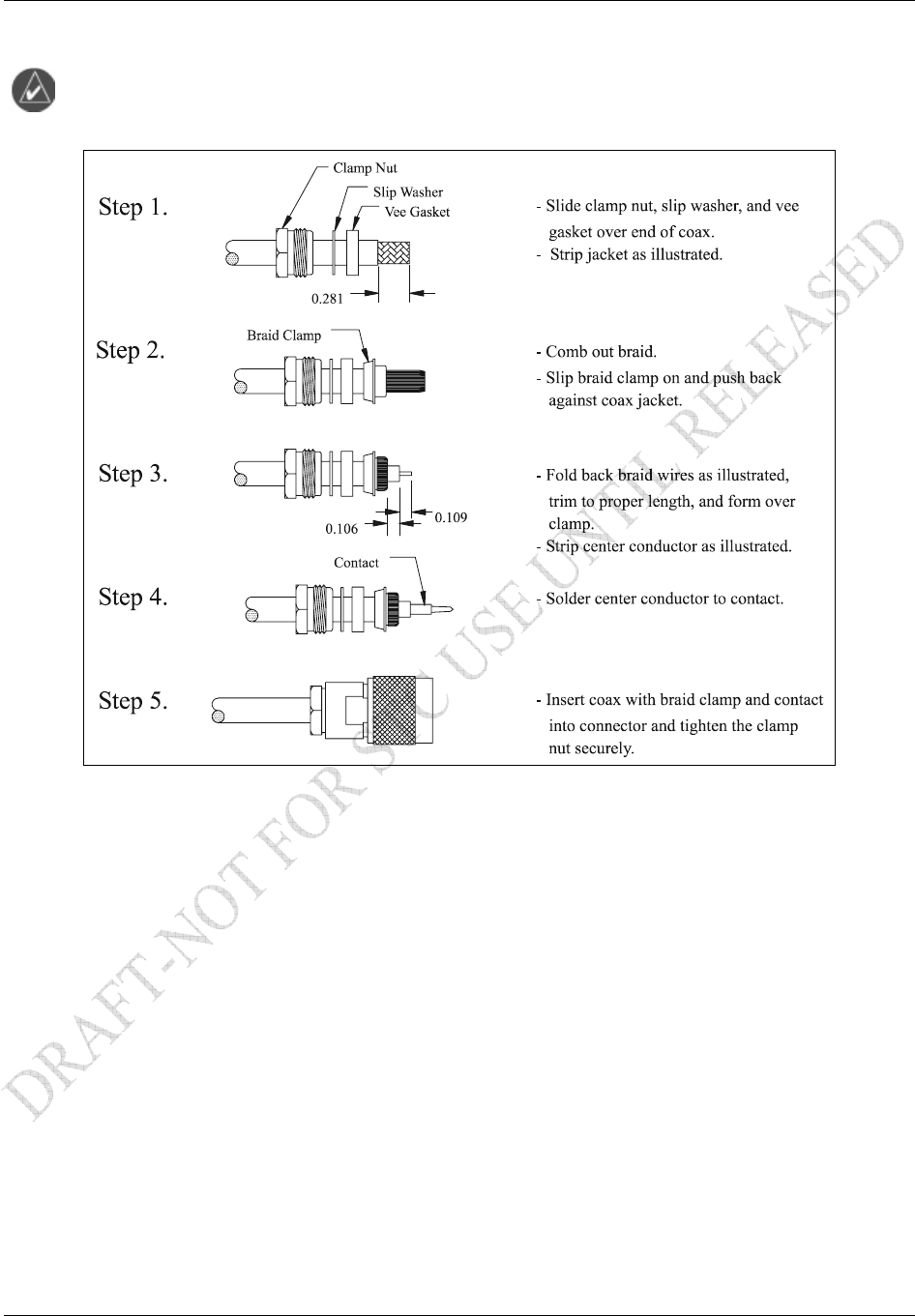
2. Trim the coaxial cable to the desired length and install TNC connectors at each end per the
cabling instructions listed in Figure 2-13. For routing convenience, one end of the coaxial run
can be terminated prior to installation.
3. With the GDL 69/69A receiver and antenna installed, route and clamp the coaxial cable in
position. Secure cable in accordance with AC 43.13-1B, Chapter 11.
Installation Procedure
Page 2-24 GDL 69/69A Installation Manual
Rev. F 190-00355-02
2.7 Weight and Balance
Weight and balance computation is required after the installation of the GDL 69/69A and optional GRT
10. Follow the guidelines as established in AC 43.13-1B, Chapter 10, Section 2. Make appropriate entries
in the equipment list indicating items added, removed, or relocated along with the date accomplished.
Include your name and certificate number in the aircraft records. Table 2-12 identifies the weight of the
new GDL 69/69A and optional GRT 10 and GRC 10 equipment. Figure 1-4, Figure 1-5, and Figure 1-6
show the center of gravity.
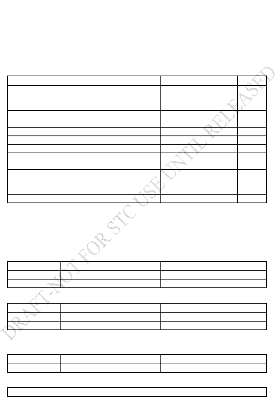
Table 2-12. Unit Weights
Item Weight Notes
GDL 69 Weight 1.72 lbs (0.78 kg)
GDL 69 and Remote Rack Weight 2.69 lbs (1.22 kg)
GDL 69 and Modular Rack Weight 2.67 lbs (1.21 kg)
GDL 69A Weight 1.86 lbs (0.84 kg)
GDL 69A and Remote Rack Weight 2.83 lbs (1.29 kg)
GDL 69A and Modular Rack Weight 2.81 lbs (1.27 kg)
GA 37 Antenna 0.50 lbs (0.23kg)
GA 55 Antenna 0.25 lbs (0.11 kg)
GA 55A Antenna 0.43 lbs (0.20 kg)
GA 57 Antenna 0.47 lbs (0.21 kg)
GRT 10 Transceiver Weight (excluding connector kit) 0.15 lbs (0.07 kg)
GRT 10 Transceiver Weight (including connector kit) 0.27 lbs (0.12 kg)
GRC 10 Remote Control Weight (without batteries) 0.23 lbs (0.11 kg) [1]
GRC 10 Remote Control Weight (with batteries) 0.34 lbs (0.15 kg) [1]
[1] The GRC 10 is a portable unit whose weight is negligible and does not need to be included in the
weight and balance computation.
2.8 Electrical Load Analysis
An electrical load analysis should be completed on each aircraft prior to installation in accordance with
AC 43.13-1B, Chapter 11 and recorded on FAA Form 337. Use the following values for computation:
GDL 69
Unit Status Max Current @ 28 VDC Max Current @ 14 VDC
Off 0.01 A 0.01 A
On 0.28 A 0.425 A
GDL 69A
Unit Status Max Current @ 28 VDC Max Current @ 14 VDC
Off 0.01 A 0.01 A
On 0.35 A 0.65 A
Note: Unit OFF is defined as the unit has power but is turned off with the remote power control signal.
GRT 10 Transceiver
Unit Status Max Current @ 28 VDC Max Current @ 14 VDC
On 36 mA 36 mA
GRC 10 Remote Control
The GRC 10 Remote Control is a portable battery-powered unit.
Installation Procedure
GDL 69/69A Installation Manual Page 2-25
190-00355-02 Rev. F
NOTE
Circuits should be protected in accordance with guidelines in AC 43.13-1B, chapter 11,
Section 2, Paragraph 429.
Figure 2-13. TNC Connector Installation
2.9 Cooling Air
The GDL 69/69A and optional GRT 10 do not require cooling air and do not generate an excessive
amount of heat during typical operations; however the thermal characteristics of the installation should
always be assessed. An undesirable thermal condition could be created due to the unit’s own internal
power dissipation combined with restricted ventilation, or due to heat generated by adjacent equipment.
Limiting thermal build up, by means of fan or natural convection is always a good practice and
recommended to increase the product life.

Installation Procedure
Page 2-26 GDL 69/69A Installation Manual
Rev. F 190-00355-02
2.10 Installing/Inserting Unit
For final installation and assembly, refer to the outline and installation drawings shown in Figure 2-2 or
Figure 2-5 of this manual. The two installation configurations available are the G1000 modular rack or
remote mount. For both configurations, insert the GDL 69/69A into the rack, noting proper orientation as
shown on the installation drawing in Figure 2-2 or Figure 2-5.
NOTE
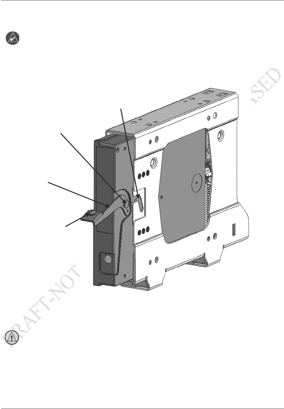
The following steps are for the remote mounting rack which is illustrated in Figure 2-14.
The steps are identical for the modular rack.
1. Loosen and remove the Locking Lever Handle Securing Screw (4). Then, lift up on the end of the
Locking Lever Handle (1).
2. Slide the GDL 69/69A unit into the Mount Rack carefully fitting the Locking Lever Handle Cam
Head (2) into the slot of the Locking Plate (3) of the Mount Rack.
3. After fully inserting the unit into the mount rack, visually note that the Cam Head (2) remains
seated in the slot of the Locking Plate (3).
Installation Procedure
GDL 69/69A Installation Manual Page 2-27
190-00355-02 Rev. F
NOTE
When inserting the GDL 69/69A into the Remote Mount Rack, it may be possible for the
Pivot Pin (2) to fit between the unit and the mount rack without going into the slot of the
Locking Plate (3). If the Cam Head (2) does not seat in the slot of the Locking Plate (3),
the unit will not firmly engage with the mount rack and the unit could come loose from
the rack.
1. With the unit firmly engaged with the mount rack, lower the Locking Lever Handle (1). Then,
insert and tighten the Locking Lever Handle Securing Screw (4) to mechanically secure the unit to
the Mount Rack.
GDL 69/69A
011-00986-00/011-00987-00
Locking Lever Handle (1)
Locking Lever Handle
Cam Head (2)
Locking Plate (3)
Locking Lever Handle
Securing Screw (4)
GDL 69/69A Remote Mount Rac
k
115-00658-00
Figure 2-14. GDL 69/69A Installation
CAUTION
Do not use excessive force when inserting the GDL 69/69A into the rack. This may
cause damage to occur to the connectors, unit, and/or unit rack. If heavy resistance is felt
during installation, STOP! Remove the GDL 69/69A and identify the source of
resistance. The unit is designed with a key and the back plate is designed to float in the
unit rack. Check to ensure the rear plate is not bound by the connector harness.

Installation Procedure
Page 2-28 GDL 69/69A Installation Manual
Rev. F 190-00355-02
This Page Intentionally Left Blank