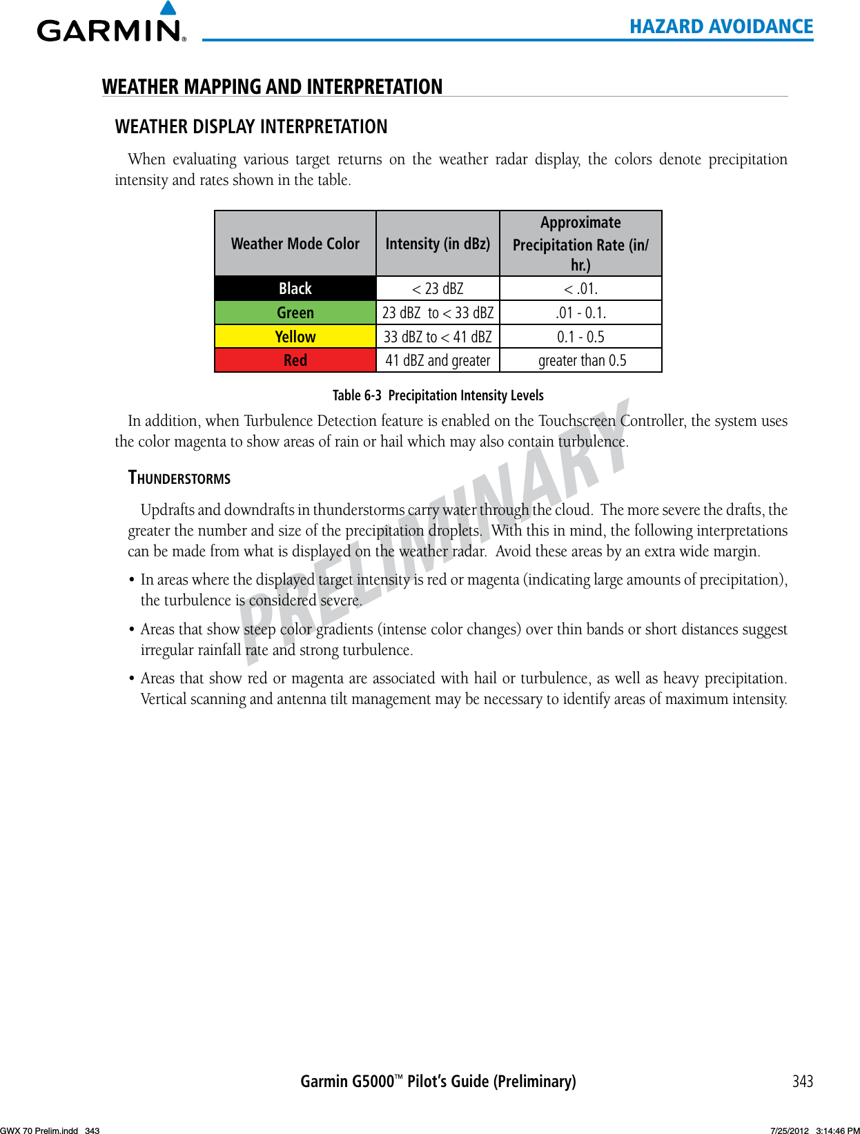
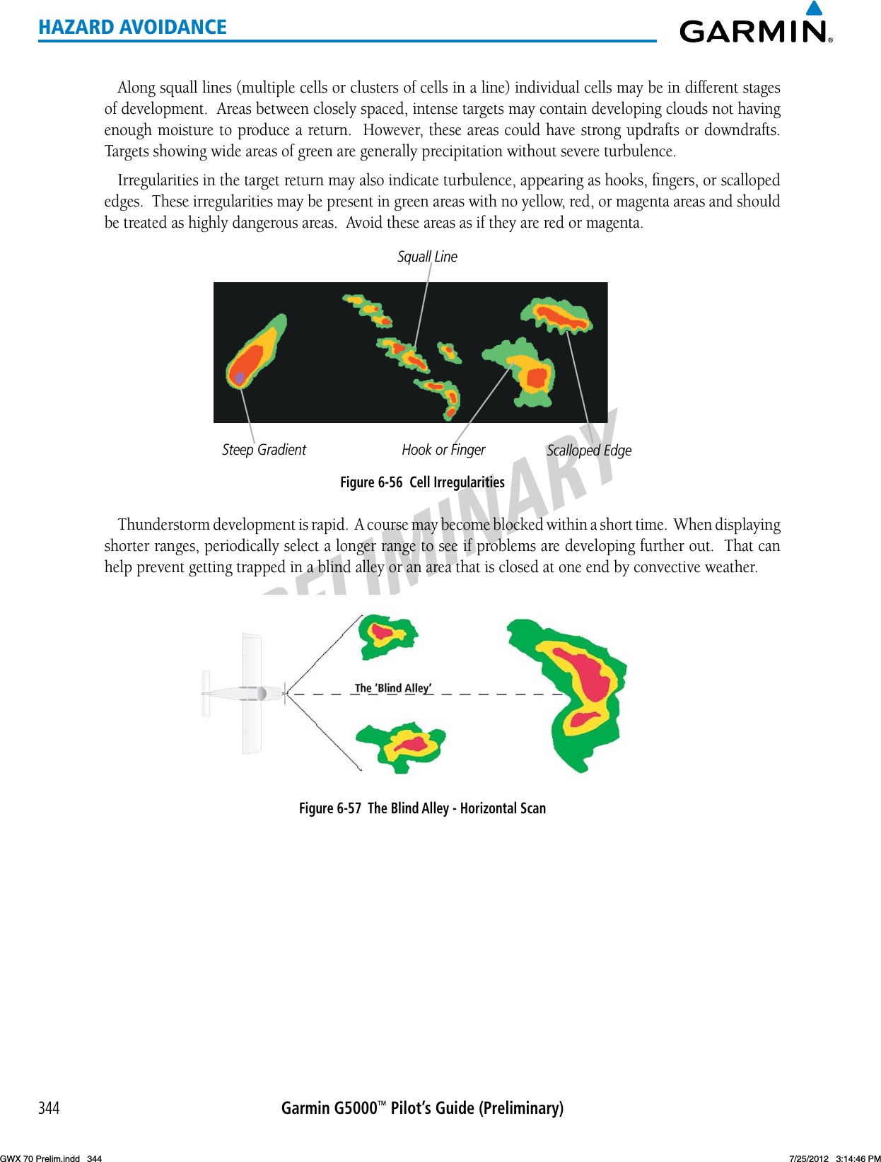
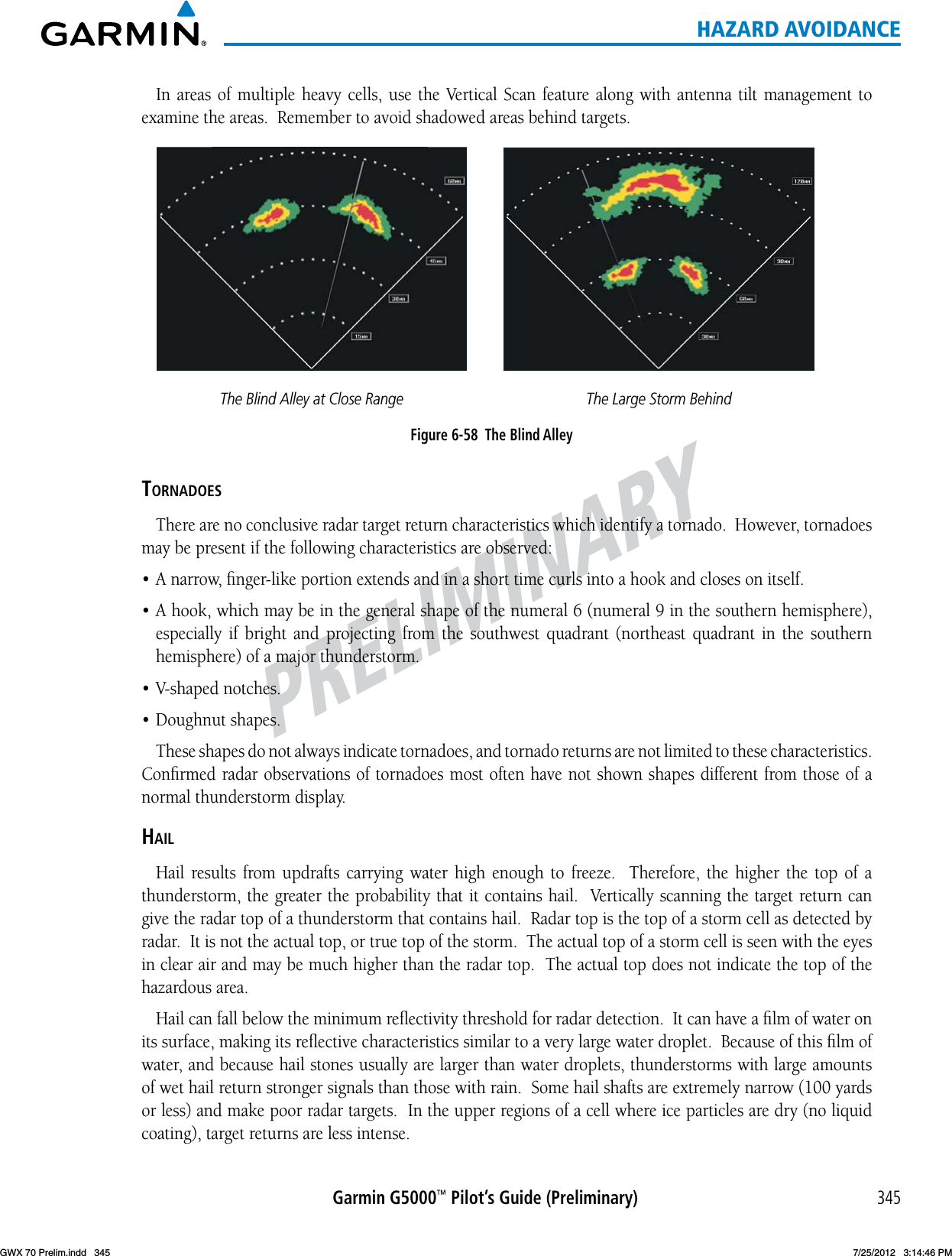
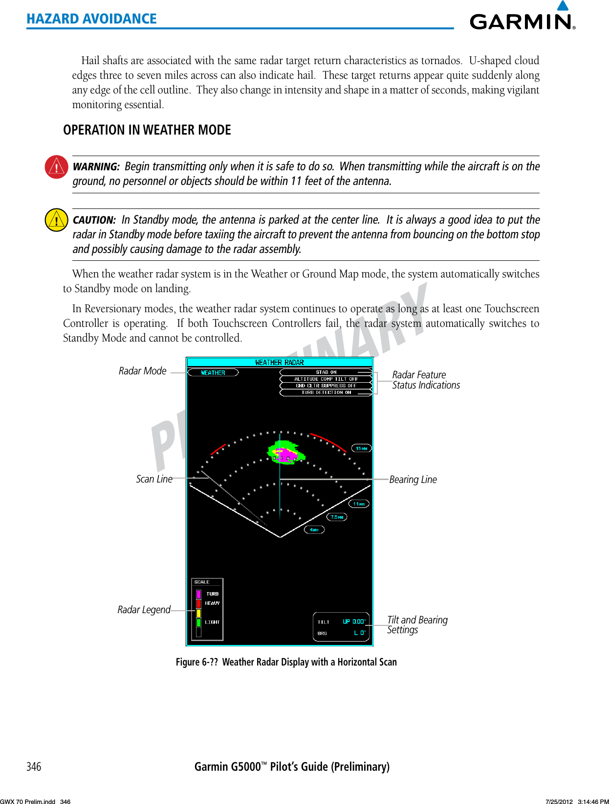
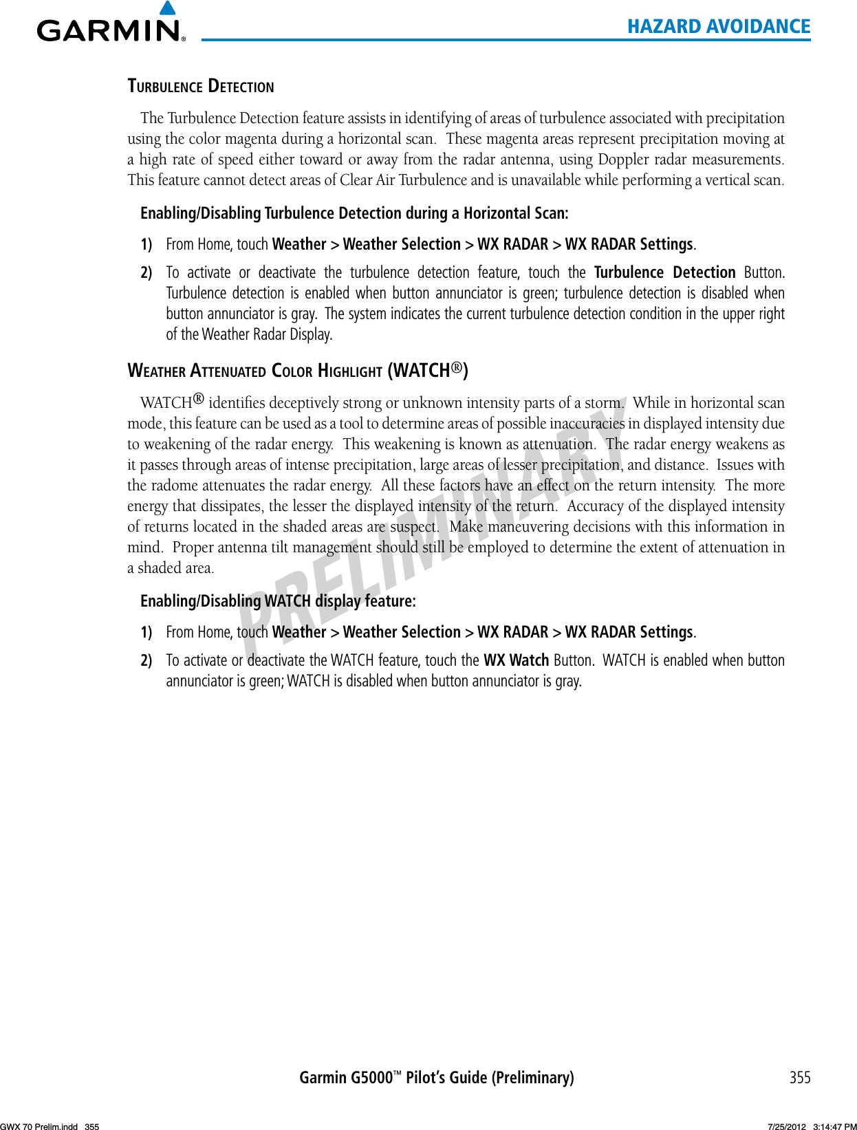
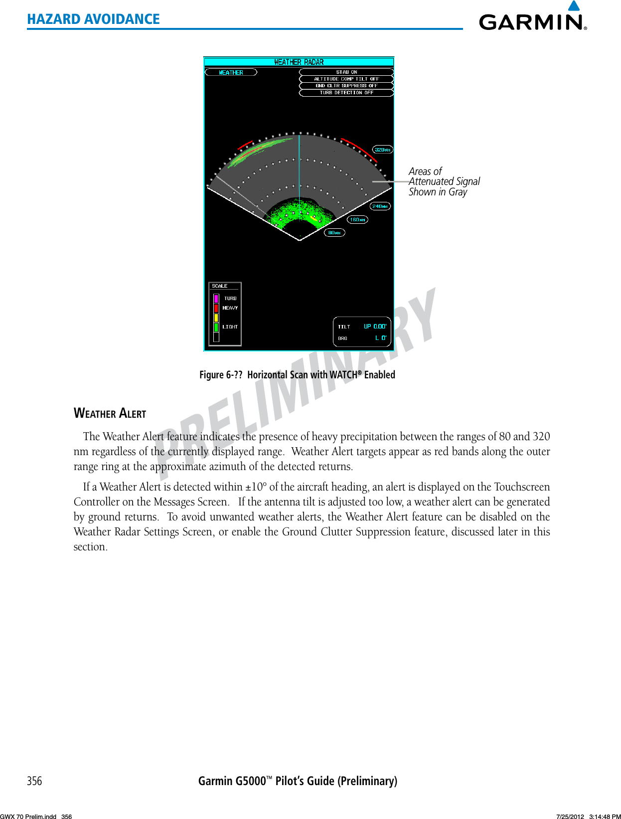
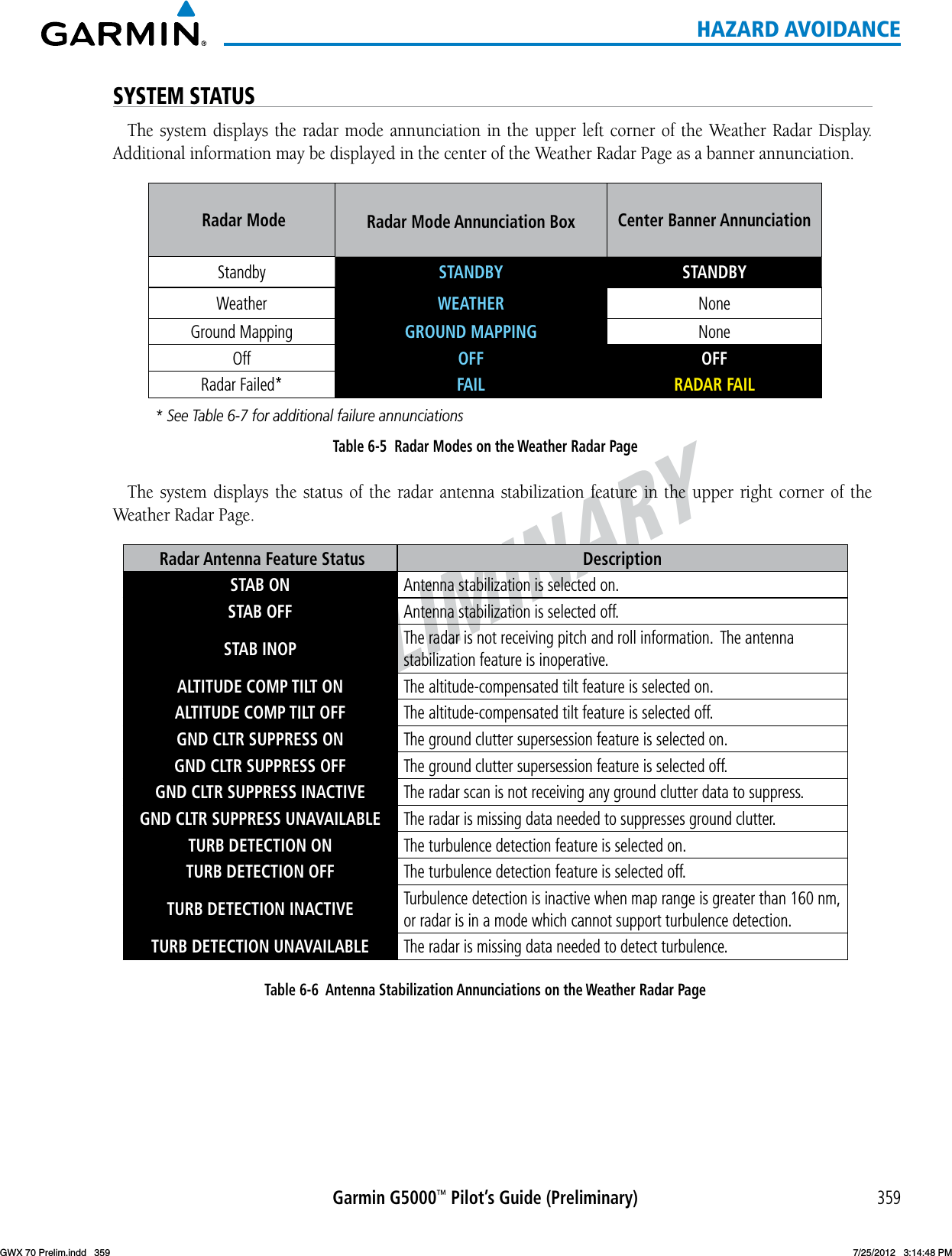
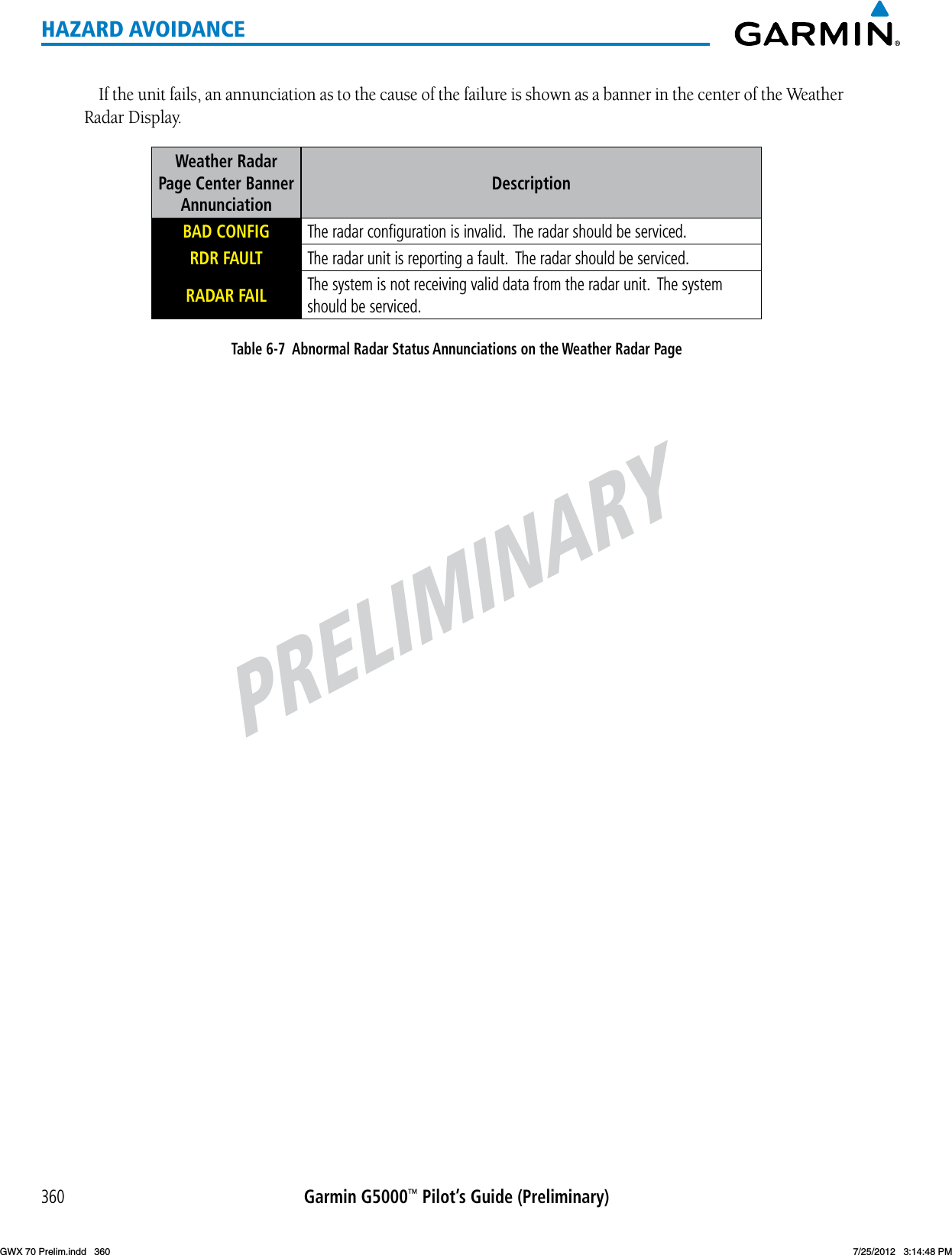
Garmin 0126000 LICENSED NON-BROADCAST BASE STATION TRANSMITTER User Manual

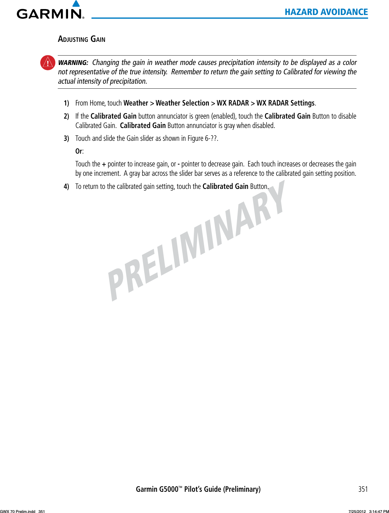
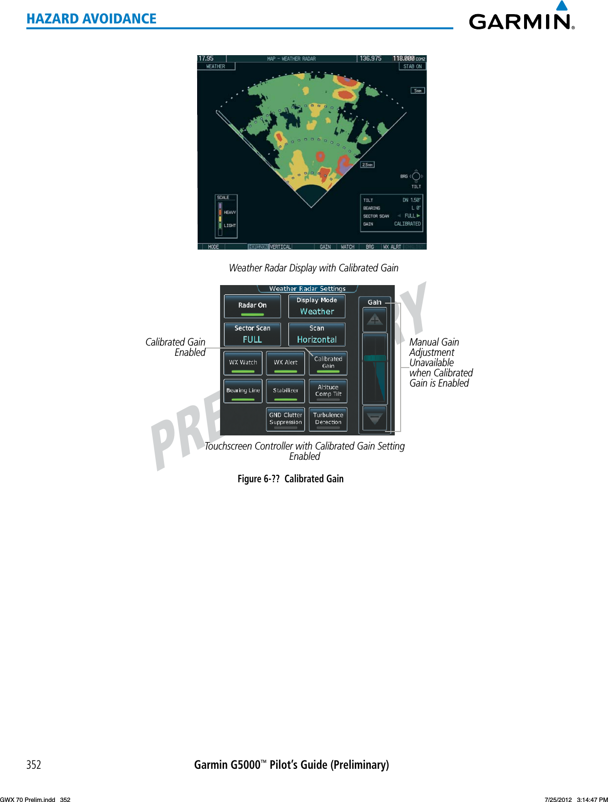
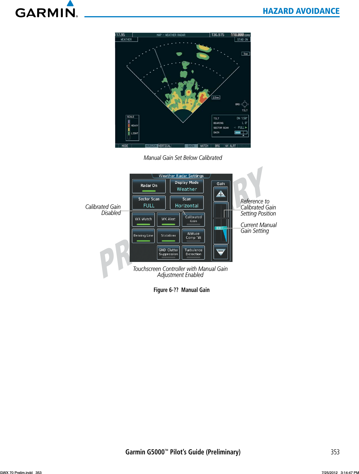
Garmin International Inc LICENSED NON-BROADCAST BASE STATION TRANSMITTER

User Manual

PRELIMINARYGarmin G5000™ Pilot’s Guide (Preliminary)335HAZARD AVOIDANCEPRELIMINARY GARMIN G5000™ PILOT’S GUIDE INCLUDING THE GARMIN GWX 70 AIRBORNE COLOR WEATHER RADARThe following contents have been extracted from a draft Garmin G5000 Pilot’s Guide.  This excerpt describes pilot operation of the Garmin GWX 70 Airborne Color Weather Radar.  This information is preliminary and is subject to change.GWX 70 Prelim.indd   335 7/25/2012   3:14:44 PM
PRELIMINARYGarmin G5000™ Pilot’s Guide (Preliminary)336HAZARD AVOIDANCE6.3  AIRBORNE COLOR WEATHER RADARSYSTEM DESCRIPTIONThe Garmin GWX 70 Airborne Color Weather Radar is a solid-state doppler radar with forty watts of output power.  It combines excellent range and adjustable scanning profiles with high-definition target displays.  The effective pulse length is 27.31 microseconds (µs), and the system optimizes the pulse length to maximize resolution at each range setting.  This reduces the targets smearing together on the displays for better target definition at close range.The aircraft uses a phased array antenna that is fully stabilized to accommodate 30º of pitch and roll.To focus radar scanning on specific areas, Sector Scanning offers pilot-adjustable horizontal scan angles of 20º, 40º, 60º, or 90º.  A vertical scanning function helps to analyze storm tops, gradients, and cell buildup activity at various altitudes.Radar features include:•ExtendedSensitivityTimeConstant(STC)logicthatautomaticallycorrelatesdistanceofthereturnechowithintensity, so cells do not suddenly appear to get larger as they get closer.•TurbulenceDetectionpresentsareasofturbulenceassociatedwithprecipitationusingthecolormagenta.•WATCH®(WeatherATtenuatedColorHighlight)helpsidentifypossibleshadowingeffectsofshort-rangecellactivity, identifying areas where radar return signals are weakened or attenuated by intense precipitation (or large areas of lesser precipitation) and may not fully reflect the weather behind a storm.•WeatherAlertthatlooksaheadforintensecellactivityinthe80-320nmrange,eveniftheserangesarenotbeing monitored.•Altitude-CompensatedTilt(ACT)managementwhichautomaticallyadjuststheantennatiltastheaircraftaltitude changes.•GroundClutterSuppression(GCS)removesgroundclutterfromthedisplays.PRINCIPLES OF AIRBORNE WEATHER RADARThetermRADARisanacronymforRAdioDetectingAndRanging.Pulsedradarlocatestargetsbytransmittinga microwave pulse beam that, upon encountering a target, is reflected back to the radar receiver as a return echo.  The microwave pulses are focused and radiated by the antenna, with the most intense energy in the center of the beam and decreasing intensity near the edge.  The same antenna is used for both transmitting and receiving.Radar detection is a two-way process that requires 12.36 µs for the transmitted microwave pulses to travel out and back for each nautical mile of target range.  It takes 123.6 µs for a transmitted pulse to make the round trip if a target is ten nautical miles away.The GWX 70, has the capability to detect the velocity of precipitation moving toward or away from the radar antenna.  As the radar pulse beam strikes a moving object, the frequency of the returned echo shifts in relation to the speed at which the object is moving.  This effect is analogous to the audibile pitch change observed when anemergencyvehicle’ssirengetscloserandthenmovesfurtheraway.Dopplerradaremploysthiseffecttodetect areas of precipitation moving at a high rate of speed (indicative of turbulence), and to determine when an object, such as the ground, is stationary.  This information can be used to suppress ground clutter.Airborne weather radar should be used to avoid severe weather, not for penetrating severe weather.  The decision to fly into an area of radar targets depends on target intensity, spacing between the targets, aircraft GWX 70 Prelim.indd   336 7/25/2012   3:14:44 PM
PRELIMINARYGarmin G5000™ Pilot’s Guide (Preliminary)337HAZARD AVOIDANCEcapabilities, and pilot experience.  Airborne weather radar detects rain or hail, not clouds or mist.  The display may indicate clear areas between intense returns, but this does not necessarily mean it is safe to fly between them.  In addition, Doppler radar measurement of precipitation velocity only occurs when rain or hail ismoving along the radar beam and either toward or away from the antenna.  The system cannot detect Clear Air Turbulence as there are no radar echoes to process.Airborne weather radar has other capabilities beyond weather detection.  It also has the ability to detect and provide distance to cities, mountains, coastlines, rivers, lakes, and oceans.NEXRAD AND AIRBORNE WEATHER RADAR BothAirborneWeatherRadarandNEXRADmeasureweatherreectivityindecibels(dB). Adecibelisalogarithmic expression of the ratio of two quantities.  Airborne Weather Radar measures the ratio of power againstthegainoftheantenna,whileNEXRADmeasurestheenergyreectedbacktotheradar,ortheradarreflectivity ratio.Both systems use colors to identify the different echo intensities, but the colors are not interchangeable.  Airborne color radar values used by Garmin Airborne Color Weather Radar should not be confused with NEXRADradarvalues.ANTENNA BEAM ILLUMINATIONThe radar beam is much like the beam of a spotlight.  The further the beam travels, the wider it becomes.  The radar is only capable of seeing what is inside the boundaries of the beam.  The figure below depicts a radar beam’s characteristics.  The figure illustrates vertical dimensions of the radar beam, although the same holds true for the horizontal dimensions.  In other words, the beam is as wide as it is tall.  Note that it is possible to miss areas of precipitation on the radar display because of the antenna tilt setting.  With the antenna tilt set to zero in this illustration, the beam overshoots the precipitation at 15 nautical miles.Figure 6-50  Radar Beam from a 12 inch Antenna080Altitude (x1000 ft.)300 45 60 75 90Range (nautical miles)Half Power at Beam SidelobesAntenna at Zero Tilt18,000 ft.18,000 ft.Max Power at Beam Center158° The curvature of the earth can also be a factor in missing areas of precipitation, especially at range settings of 150nauticalmilesormore.Herethebeamovershootstheprecipitationatlessthan320nauticalmiles.GWX 70 Prelim.indd   337 7/25/2012   3:14:44 PM
PRELIMINARYGarmin G5000™ Pilot’s Guide (Preliminary)338HAZARD AVOIDANCE320 nm Figure 6-51  Radar Beam in Relation to the  Curvature of the EarthRADAR SIGNAL ATTENUATIONThe phenomenon of radar signal attenuation affects the operation of weather radar.  When the radar signal is transmitted, it is progressively absorbed and scattered, making the signal weaker.  This weakening, or attenuation, is caused by two primary sources, distance and precipitation.Attenuation because of distance is due to the fact that the radar energy leaving the antenna is inversely proportional to the square of the distance.  The reflected radar energy from a target 40 miles away that fills the radar beam is one fourth the energy reflected from an equivalent target 20 miles away.  This would appear to the operator that the storm is gaining intensity as the aircraft gets closer.  Internal signal processing within the GWX 70 system compensates for much of this distance attenuation.Attenuation due to precipitation is not as predictable as distance attenuation.  It is also more intense.  As the radarsignalpassesthroughmoisture,aportionoftheradarenergyisreectedbacktotheantenna.However,much of the energy is absorbed.  If precipitation is very heavy, or covers a large area, the signal may not reach completely through the area of precipitation.  The weather radar system cannot distinguish between an attenuated signal and an area of no precipitation.  If the signal has been fully attenuated, the radar displays a radar shadow.  This appears as an end to the precipitation when, in fact, the heavy rain may extend much further.  A cell containing heavy precipitation may block another cell located behind the first, preventing it from being displayed on the radar.  Never fly into these shadowed areas and never assume that all of the heavy precipitation is being displayed unless another cell or a ground target can be seen beyond the heavy cell.  The WATCH® feature of the GWX 70 Weather Radar system can help in identifying these shadowed areas.  Areas in question appear as shadowed or gray on the radar display.  Proper use of the antenna tilt control can also help detect radar shadows.Attenuationcanalsobeduetopoormaintenanceordegradationoftheradome.Eventhesmallestamountof wear and scratching, pitting, and pinholes on the radome surface can cause damage and system inefficiency.RADAR SIGNAL REFLECTIVITYPreciPitationPrecipitation or objects more dense than water, such as the surface of the earth or solid structures, are detected by the weather radar.  The weather radar does not detect clouds, thunderstorms, or turbulence directly.  It detects precipitation associated with clouds, thunderstorms, and turbulence.  The best radar signal reflectors are raindrops, wet snow, or wet hail.  The larger the raindrop, the better the reflectivity.  The size of the precipitation droplet is the most important factor in radar reflectivity.  Because large drops in a small concentrated area are characteristic of a severe thunderstorm, the radar displays the storm as a strong return.  Ice crystals, dry snow, and dry hail have low levels of reflectivity as shown in the illustration, and GWX 70 Prelim.indd   338 7/25/2012   3:14:45 PM
PRELIMINARYGarmin G5000™ Pilot’s Guide (Preliminary)339HAZARD AVOIDANCEoften not displayed by the radar.  Additionally, a cloud that contains only small raindrops, such as fog or drizzle, does not reflect enough radar energy to produce a measurable target return.Figure 6-52  Precipitation Type and ReflectivityGround returnsThe intensity of ground target returns depends upon the angle at which the radar beam strikes the ground target (Angle of Incidence) and the reflective properties of that target.  The gain can be adjusted so shorelines, rivers, lakes, and cities are well defined.  Increasing the gain too much causes the display to fill in between targets, thus obscuring some landmarks.Cities normally provide a strong return signal.  While large buildings and structures provide good returns, small buildings can be shadowed from the radar beam by the taller buildings.  As the aircraft approaches and shorter ranges are selected, details become more noticeable as the highly reflective regular lines and edges of the city become more defined.Bodies of water such as lakes, rivers, and oceans are not good reflectors and normally do not provide good returns.  The energy is reflected in a forward scatter angle with inadequate energy being returned.  They canappearasdarkareasonthedisplay.However,roughorchoppywaterisabetterreectorandprovidesstronger returns from the downwind sides of the waves.Mountainsalsoprovidestrongreturnsignalstotheantenna,butalsoblocktheareasbehind.However,over mountainous terrain, the radar beam can be reflected back and forth in the mountain passes or off canyon walls, using up all or most of the radar energy.  In this case, no return signal is received from this area, causing the display to show a dark spot which could indicate a pass where no pass exists. anGle of incidenceThe angle at which the radar beam strikes the target is called the Angle of Incidence.  The figure illustrates the incident angle (‘A’).  This directly affects the detectable range, the area of illumination, and the intensity of the displayed target returns.  A large incident angle gives the radar system a smaller detectable range and lower display intensity due to minimized reflection of the radar energy.GWX 70 Prelim.indd   339 7/25/2012   3:14:45 PM
PRELIMINARYGarmin G5000™ Pilot’s Guide (Preliminary)340HAZARD AVOIDANCEFigure 6-53  Angle of IncidenceA smaller incident angle gives the radar a larger detectable range of operation and the target display shows a higher intensity.  Since more radar energy is reflected back to the antenna with a low incident angle, the resulting detectable range is increased for mountainous terrain.SAFE OPERATING DISTANCEThe following information establishes a minimum safe distance from the antenna for personnel near operatingweatherradar.TheminimumsafedistanceisbasedontheFCC’sexposurelimitat9.3to9.5GHzforgeneralpopulation/uncontrolledenvironments,whichis1mW/cm2.SeeAdvisoryCircular20-68Bformoreinformation on safe distance determination.MAXIMUM PERMISSIBLE EXPOSURE LEVEL (MPEL)The zone in which the radiation level exceeds the US Government standard of 1 mW/cm2 is the semicircular area of at least 11 feet from the 12-inch antenna.  All personnel must remain outside of this zone.  With a scanningorrotatingbeam,theaveragedpowerdensityattheMPELboundaryissignicantlyreduced.  11’ for 12” antenna MPEL Boundary  Figure 6-54  MPEL BoundaryBASIC ANTENNA TILT SETUPGWX 70 Prelim.indd   340 7/25/2012   3:14:45 PM
PRELIMINARYGarmin G5000™ Pilot’s Guide (Preliminary)341HAZARD AVOIDANCEThe following discussion is a simple method for setting up the weather radar antenna tilt for most situations.  It is not to be considered an all encompassing setup that works in all situations, but this method does provide good overall parameters for the monitoring of threats.  Ultimately, it is desired to have the antenna tilted so that the bottom of the radar beam is four degrees below parallel with the ground.  The following example explains one way of achieving this.With the aircraft flying level, adjust the antenna tilt so ground returns are displayed at a distance that equals theaircraft’scurrentaltitude(AGL)dividedby1,000.Forexample,iftheaircraftisat14,000feet,adjustthetilt so the front edge of ground returns are displayed at 14 nautical miles.  Note this antenna tilt angle setting.  Now, raise the antenna tilt 6 degrees above this setting.  The bottom of the radar beam is now angled down 4º from parallel with the ground.GWX 70 Prelim.indd   341 7/25/2012   3:14:45 PM
PRELIMINARYGarmin G5000™ Pilot’s Guide (Preliminary)342HAZARD AVOIDANCEPRACTICAL APPLICATION USING THE BASIC TILT SETUPWith the antenna tilt set as previously described, any displayed target return should be scrutinized when yingataltitudesbetween2,000and30,000feetAGL.Ifthedisplayedtargetadvancesonthescreentowithin 5 nautical miles of the aircraft, avoid it.  This may be either weather or ground returns that are 2,000 feet or less below the aircraft.  Raising the antenna tilt 4 degrees can help separate ground returns from weather returns in relatively flat terrain.  This aligns the bottom of the radar beam parallel with the ground.  Return the antenna tilt to the previous setting after a few sweeps.If the aircraft is above 29,000 feet, be cautious of any target return that gets to within 30 nautical miles.  This is likely a thunderstorm that has a top high enough that the aircraft cannot fly over it safely.If the aircraft altitude is 15,000 feet or lower, setting the displayed range to 60 miles may be more helpful.  Closely monitor anything that enters the display.Also, after setting up the antenna tilt angle as described previously, ground returns can be monitored for possible threats.  The relationship between antenna tilt angle, altitude, and distance is one degree of tilt equals 100 feet of altitude for every one nautical mile.Vertical Change of Radar Beam (feet) Change in Antenna Tilt 10 nm 0 1000 2000 3000 4000 1000 2000 3000 4000  -1° 0° -2° -3° -4° +1° +2° +3° +4° Figure 6-55  Vertical Change in Radar Beam per Nautical MileTherefore, with the antenna tilt set so that the bottom of the beam is four degrees below parallel with theground,atargetreturnat10nmisapproximately4,000feetbelowtheaircraft;at20nm,8,000feet;at 50 nm, 20,000 feet.  In other words, at this tilt setting, a ground return (such as a mountain peak) being displayed at 10 nm would have a maximum distance below the aircraft of 4,000 feet.  A  ground target return being displayed at 5 nm would have a maximum distance below the aircraft of 2,000 feet.  This setup provides a good starting point for practical use of the GWX 70.  There are many other factors to consider in order to become proficient at using weather radar in all situations.ALTITUDE COMPENSATED TILT (ACT)The Altitude Compensated Tilt feature of the GWX 70 enables the system to automatically adjust the antenna beam tilt angle setting based on changes of the aircraft’s altitude.  For example, if the ACT feature is enabled and the aircraft climbs, the system compensates by adjusting the tilt downward.  As the aircraft descends with ACT enabled, the system adjusts the antenna tilt upward.  The system uses the ground as a reference for adjusting the antenna tilt setting with ACT enabled.GWX 70 Prelim.indd   342 7/25/2012   3:14:45 PM
PRELIMINARYGarmin G5000™ Pilot’s Guide (Preliminary)343HAZARD AVOIDANCEWEATHER MAPPING AND INTERPRETATIONWEATHER DISPLAY INTERPRETATIONWhen evaluating various target returns on the weather radar display, the colors denote precipitation intensity and rates shown in the table.Weather Mode Color Intensity (in dBz)ApproximatePrecipitation Rate (in/hr.)Black < 23 dBZ < .01.Green 23 dBZ  to < 33 dBZ .01 - 0.1.Yellow 33 dBZ to < 41 dBZ 0.1 - 0.5Red 41 dBZ and greater  greater than 0.5Table 6-3  Precipitation Intensity LevelsInaddition,whenTurbulenceDetectionfeatureisenabledontheTouchscreenController,thesystemusesthe color magenta to show areas of rain or hail which may also contain turbulence.thunderstormsUpdrafts and downdrafts in thunderstorms carry water through the cloud.  The more severe the drafts, the greater the number and size of the precipitation droplets.  With this in mind, the following interpretations can be made from what is displayed on the weather radar.  Avoid these areas by an extra wide margin.•Inareaswherethedisplayedtargetintensityisredormagenta(indicatinglargeamountsofprecipitation),the turbulence is considered severe. •Areasthatshowsteepcolorgradients(intensecolorchanges)overthinbandsorshortdistancessuggestirregular rainfall rate and strong turbulence.•Areasthatshowredormagentaareassociatedwithhailorturbulence,aswellasheavyprecipitation.Vertical scanning and antenna tilt management may be necessary to identify areas of maximum intensity.GWX 70 Prelim.indd   343 7/25/2012   3:14:46 PM
PRELIMINARYGarmin G5000™ Pilot’s Guide (Preliminary)344HAZARD AVOIDANCEAlong squall lines (multiple cells or clusters of cells in a line) individual cells may be in different stages of development.  Areas between closely spaced, intense targets may contain developing clouds not having enoughmoisturetoproduceareturn.However,theseareascouldhavestrongupdraftsordowndrafts.Targets showing wide areas of green are generally precipitation without severe turbulence.  Irregularities in the target return may also indicate turbulence, appearing as hooks, fingers, or scalloped edges.  These irregularities may be present in green areas with no yellow, red, or magenta areas and should be treated as highly dangerous areas.  Avoid these areas as if they are red or magenta.Figure 6-56  Cell IrregularitiesSteep GradientSquall LineHook or Finger Scalloped EdgeThunderstorm development is rapid.  A course may become blocked within a short time.  When displaying shorter ranges, periodically select a longer range to see if problems are developing further out.  That can help prevent getting trapped in a blind alley or an area that is closed at one end by convective weather.Figure 6-57  The Blind Alley - Horizontal ScanGWX 70 Prelim.indd   344 7/25/2012   3:14:46 PM
PRELIMINARYGarmin G5000™ Pilot’s Guide (Preliminary)345HAZARD AVOIDANCEIn areas of multiple heavy cells, use the Vertical Scan feature along with antenna tilt management to examine the areas.  Remember to avoid shadowed areas behind targets.Figure 6-58  The Blind AlleyThe Blind Alley at Close Range The Large Storm BehindtornadoesTherearenoconclusiveradartargetreturncharacteristicswhichidentifyatornado.However,tornadoesmay be present if the following characteristics are observed:•Anarrow,nger-likeportionextendsandinashorttimecurlsintoahookandclosesonitself.•Ahook,whichmaybeinthegeneralshapeofthenumeral6(numeral9inthesouthernhemisphere),especially if bright and projecting from the southwest quadrant (northeast quadrant in the southern hemisphere) of a major thunderstorm.•V-shapednotches.•Doughnutshapes.These shapes do not always indicate tornadoes, and tornado returns are not limited to these characteristics. Confirmed radar observations of tornadoes most often have not shown shapes different from those of a normal thunderstorm display.hailHail results from updrafts carrying water high enough to freeze.  Therefore, the higher the top of athunderstorm, the greater the probability that it contains hail.  Vertically scanning the target return can give the radar top of a thunderstorm that contains hail.  Radar top is the top of a storm cell as detected by radar.  It is not the actual top, or true top of the storm.  The actual top of a storm cell is seen with the eyes in clear air and may be much higher than the radar top.  The actual top does not indicate the top of the hazardous area.Hailcanfallbelowtheminimumreectivitythresholdforradardetection.Itcanhavealmofwateronits surface, making its reflective characteristics similar to a very large water droplet.  Because of this film of water, and because hail stones usually are larger than water droplets, thunderstorms with large amounts of wet hail return stronger signals than those with rain.  Some hail shafts are extremely narrow (100 yards or less) and make poor radar targets.  In the upper regions of a cell where ice particles are dry (no liquid coating), target returns are less intense.GWX 70 Prelim.indd   345 7/25/2012   3:14:46 PM
PRELIMINARYGarmin G5000™ Pilot’s Guide (Preliminary)346HAZARD AVOIDANCEHailshaftsareassociatedwiththesameradartargetreturncharacteristicsastornados.U-shapedcloudedges three to seven miles across can also indicate hail.  These target returns appear quite suddenly along any edge of the cell outline.  They also change in intensity and shape in a matter of seconds, making vigilant monitoring essential.OPERATION IN WEATHER MODE WARNING:  Begin transmitting only when it is safe to do so.  When transmitting while the aircraft is on the ground, no personnel or objects should be within 11 feet of the antenna. CAUTION:  In Standby mode, the antenna is parked at the center line.  It is always a good idea to put the radar in Standby mode before taxiing the aircraft to prevent the antenna from bouncing on the bottom stop and possibly causing damage to the radar assembly.When the weather radar system is in the Weather or Ground Map mode, the system automatically switches to Standby mode on landing.In Reversionary modes, the weather radar system continues to operate as long as at least one Touchscreen Controller is operating.  If both Touchscreen Controllers fail, the radar system automatically switches to Standby Mode and cannot be controlled.Figure 6-??  Weather Radar Display with a Horizontal ScanRadar ModeRadar LegendRadar Feature Status IndicationsScan Line Bearing LineTilt and Bearing SettingsGWX 70 Prelim.indd   346 7/25/2012   3:14:46 PM
PRELIMINARYGarmin G5000™ Pilot’s Guide (Preliminary)347HAZARD AVOIDANCEShowing Weather Radar Data on the Weather Radar Display:1)  From Home, touch Weather > Weather Selection > WX RADAR > WX RADAR Settings.2)  Touch the Radar On Button.  Radar options are enabled when button annunciator is green, off when gray.3)  Touch the Display Mode Button. 4)  Touch the Weather Button.  If the aircraft is airborne, the radar begins transmitting.5)  If the aircraft is on the ground, the Touchscreen Controller displays a prompt shown in the figure below to confirm radar activation.  Touch the OK Button to begin transmitting, or touch the Cancel Button to return to the Weather Radar Settings screen.Figure 6-??  Confirm Activating Radar while on Ground4)  Turn the Joystick to select the desired map range.5)  The system displays a horizontal scan.  To change to a vertical scan, refer to the following procedure, “Vertically scanning a storm cell.”GWX 70 Prelim.indd   347 7/25/2012   3:14:46 PM
PRELIMINARYGarmin G5000™ Pilot’s Guide (Preliminary)348HAZARD AVOIDANCEVertically scanning a storm cell: NOTE:  Vertical scanning of a storm cell should be done with the aircraft wings level to avoid constant adjustment of the Bearing Line.1)  From Home, touch Weather > Weather Selection > WX RADAR > WX RADAR Settings.2)  While on a Horizontal Scan view, touch the Bearing Line Button if necessary to show the Bearing Line on the Weather Radar Pane.2)  Press the Joystick.  This enables the Joystick to set the Bearing Line position and displays a bearing and tilt Joystick legend.3)  Push the Joystick left or right to place the Bearing Line on the desired storm cell or other area to be vertically scanned.  When finished, press the Joystick again to disable the bearing line adjustment Joystick function.Figure 6-??  Weather Radar Display with a Horizontal ScanScan Line Bearing Line on a Horizontal Scan4)  Touch the Scan Button.5)  Touch the Vertical Button.  The Weather Radar display shows a vertical scan.6)  Push the Joystick left or right as needed to move the bearing line a few degrees left or right.7)  Turn the Joystick to adjust the range as needed.8)  To select a new area to be vertically scanned, return to the Horizontal scan mode. a)  Touch the Scan Button. b)  Touch the Horizontal Button. c)  Return to Step 2 of this procedure.GWX 70 Prelim.indd   348 7/25/2012   3:14:46 PM
PRELIMINARYGarmin G5000™ Pilot’s Guide (Preliminary)349HAZARD AVOIDANCEFigure 6-??  Weather Radar Display with Vertical Scan Mode SelectedadjustinG antenna tilt anGleIn order to make an accurate interpretation of a storm cell, the radar beam should be pointed at the wet part of the weather cell to record the proper rainfall intensity (color level).  The ideal aiming point is just below the freezing level of the storm.  The best way to find this point is to use the Vertical Scan feature.  The antenna tilt angle can be centered on the strongest return area in the vertical scan to get a more accurate view of the coverage and intensity of the target in the horizontal scan.Adjusting antenna tilt on the Weather Radar Display in Horizontal Scan Mode:1)  Push the Joystick to activate the tilt adjustment function of the Joystick.  The Weather Radar displays a bearing and tilt Joystick legend.2)  Use the Joystick to adjust the antenna tilt angle.3)  Press the Joystick again to disable the tilt adjustment function of the Joystick and remove the legend.GWX 70 Prelim.indd   349 7/25/2012   3:14:46 PM
PRELIMINARYGarmin G5000™ Pilot’s Guide (Preliminary)350HAZARD AVOIDANCEaltitude comPensated tilt (act) anGle adjustmentThe Attitude Compensated Tilt feature enables automatic management of the antenna tilt angle as the aircraft altitude changes.  With ACT enabled, the antenna beam position remains centered at the set position for the current map range.  The system automatically decreases the tilt angle as the aircraft climbs, and increasesthetiltangleastheaircraftdescends.ACTisavailableintheHorizontalScanModewhenthesystem is operating in Weather Mode.Enabling/Disabling Altitude Compensated Tilt (ACT):1)  From Home, touch Weather > Weather Selection > WX RADAR > WX RADAR Settings.2)  Touch the Altitude Comp Tilt Button.  Feature is enabled when button annunciator is green, disabled when gray.Adjusting antenna tilt on the Weather Radar Display in Vertical Scan Mode:1)  While in Vertical Scan Mode, press the Joystick to activate the tilt adjustment function of the Joystick and display the Tilt Line on the Weather Radar Display.2)  Use the Joystick to adjust the tilt angle.3)  Press the Joystick to disable the tilt adjustment function of the Joystick.TheselectedtiltanglewillapplywhenHorizontalScanModeisenabledagain.Figure 6-63  Adjusting Tilt on Vertical Scan DisplayTilt LineScan LineGWX 70 Prelim.indd   350 7/25/2012   3:14:47 PM
PRELIMINARYGarmin G5000™ Pilot’s Guide (Preliminary)351HAZARD AVOIDANCEadjustinG Gain WARNING:  Changing the gain in weather mode causes precipitation intensity to be displayed as a color not representative of the true intensity.  Remember to return the gain setting to Calibrated for viewing the actual intensity of precipitation.1)  From Home, touch Weather > Weather Selection > WX RADAR > WX RADAR Settings.2)  If the Calibrated Gain button annunciator is green (enabled), touch the Calibrated Gain Button to disable Calibrated Gain.  Calibrated Gain Button annunciator is gray when disabled.3)  Touch and slide the Gain slider as shown in Figure 6-??. Or:    Touch the + pointer to increase gain, or - pointer to decrease gain.  Each touch increases or decreases the gain by one increment.  A gray bar across the slider bar serves as a reference to the calibrated gain setting position.4)  To return to the calibrated gain setting, touch the Calibrated Gain Button.GWX 70 Prelim.indd   351 7/25/2012   3:14:47 PM
PRELIMINARYGarmin G5000™ Pilot’s Guide (Preliminary)352HAZARD AVOIDANCEWeather Radar Display with Calibrated GainCalibrated Gain Enabled Manual Gain Adjustment Unavailable when Calibrated Gain is EnabledTouchscreen Controller with Calibrated Gain Setting EnabledFigure 6-??  Calibrated GainGWX 70 Prelim.indd   352 7/25/2012   3:14:47 PM
PRELIMINARYGarmin G5000™ Pilot’s Guide (Preliminary)353HAZARD AVOIDANCEManual Gain Set Below CalibratedCalibrated Gain DisabledCurrent Manual Gain SettingReference to Calibrated Gain Setting PositionTouchscreen Controller with Manual Gain Adjustment EnabledFigure 6-??  Manual GainGWX 70 Prelim.indd   353 7/25/2012   3:14:47 PM
PRELIMINARYGarmin G5000™ Pilot’s Guide (Preliminary)354HAZARD AVOIDANCEsector scan1)  From Home, touch Weather > Weather Selection > WX RADAR > WX RADAR Settings.2)  While in Horizontal Scan Mode, touch the Bearing Line Button if necessary to show the Bearing Line on the Weather Radar display/.2)  Press the Joystick to enable bearing pointer adjustment.3)  Move the Joystick left or right to place the Bearing Line in the desired position.  The location of the Bearing Line becomes the center point of the Sector Scan.4)  Touch the Sector Scan Button.5)  Touch a button to select a 20˚, 40˚, 60˚, 90˚, or touch the FULL Button to resume a 120˚ degree scan.6)  If desired, readjust the Bearing Line as discussed previously to change the center of the Sector Scan.7)  Press the Joystick again to remove the bearing selection function of the Joystick.  The bearing reference is reset to 0º.Figure 6-??  Weather Radar Display on a 60 Degree Sector Scanantenna stabilization1)  From Home, touch Weather > Weather Selection > WX RADAR > WX RADAR Settings.2)  To activate or deactivate the antenna stabilization, touch the Stabilizer Button.  Antenna stabilization is enabled when button annunciator is green; stabilization is disabled when button annunciator is gray.  The system indicates the current stabilization condition in the upper right of the Weather Radar Display.GWX 70 Prelim.indd   354 7/25/2012   3:14:47 PM
PRELIMINARYGarmin G5000™ Pilot’s Guide (Preliminary)355HAZARD AVOIDANCEturbulence detectionTheTurbulenceDetectionfeatureassistsinidentifyingofareasofturbulenceassociatedwithprecipitationusing the color magenta during a horizontal scan.  These magenta areas represent precipitation moving at ahighrateofspeedeithertowardorawayfromtheradarantenna,usingDopplerradarmeasurements.This feature cannot detect areas of Clear Air Turbulence and is unavailable while performing a vertical scan.Enabling/Disabling Turbulence Detection during a Horizontal Scan:1)  From Home, touch Weather > Weather Selection > WX RADAR > WX RADAR Settings.2)  To activate or deactivate the turbulence detection feature, touch the Turbulence Detection  Button.  Turbulence detection is enabled when button annunciator is green; turbulence detection is disabled when button annunciator is gray.  The system indicates the current turbulence detection condition in the upper right of the Weather Radar Display.Weather attenuated color hiGhliGht (Watch®)WATCH® identifies deceptively strong or unknown intensity parts of a storm.  While in horizontal scan mode, this feature can be used as a tool to determine areas of possible inaccuracies in displayed intensity due to weakening of the radar energy.  This weakening is known as attenuation.  The radar energy weakens as it passes through areas of intense precipitation, large areas of lesser precipitation, and distance.  Issues with the radome attenuates the radar energy.  All these factors have an effect on the return intensity.  The more energy that dissipates, the lesser the displayed intensity of the return.  Accuracy of the displayed intensity of returns located in the shaded areas are suspect.  Make maneuvering decisions with this information in mind.  Proper antenna tilt management should still be employed to determine the extent of attenuation in a shaded area.Enabling/Disabling WATCH display feature:1)  From Home, touch Weather > Weather Selection > WX RADAR > WX RADAR Settings.2)  To activate or deactivate the WATCH feature, touch the WX Watch Button.  WATCH is enabled when button annunciator is green; WATCH is disabled when button annunciator is gray. GWX 70 Prelim.indd   355 7/25/2012   3:14:47 PM
PRELIMINARYGarmin G5000™ Pilot’s Guide (Preliminary)356HAZARD AVOIDANCEFigure 6-??  Horizontal Scan with WATCH® EnabledAreas of Attenuated Signal Shown in GrayWeather alertTheWeatherAlertfeatureindicatesthepresenceofheavyprecipitationbetweentherangesof80and320nm regardless of the currently displayed range.  Weather Alert targets appear as red bands along the outer range ring at the approximate azimuth of the detected returns.If a Weather Alert is detected within ±10° of the aircraft heading, an alert is displayed on the Touchscreen Controller on the Messages Screen.   If the antenna tilt is adjusted too low, a weather alert can be generated by ground returns.  To avoid unwanted weather alerts, the Weather Alert feature can be disabled on the Weather Radar Settings Screen, or enable the Ground Clutter Suppression feature, discussed later in this section.GWX 70 Prelim.indd   356 7/25/2012   3:14:48 PM
PRELIMINARYGarmin G5000™ Pilot’s Guide (Preliminary)357HAZARD AVOIDANCEFigure 6-??  Weather Alerts on the Weather Radar DisplayWeather Alert Indicates Possible Severe Weather AheadEnabling/Disabling Weather Alert:1)  From Home, touch Weather > Weather Selection > WX RADAR > WX RADAR Settings.2)  To enable or disable the Weather Alert feature, touch the WX Alert Button.  Alert is enabled when button annunciator is green; alert is disabled when annunciator is gray.removinG Ground clutterThe system can distinguish between reflected ground returns (such as terrain features and buildings) and airborne weather phenomena.  Ground clutter may be most pronounced when using a low antenna tilt angle, or when approaching mountainous terrain.When Ground Clutter suppression is enabled, the system removes ground clutter from the display.Enabling/Disabling Ground Clutter Suppression:1)  From Home, touch Weather > Weather Selection > WX RADAR > WX RADAR Settings.2)  To enable or disable the ground clutter suppression feature, touch the GND Cluttter Suppression  Button.  Ground clutter suppression is enabled when button annunciator is green; ground clutter suppression is disabled when annunciator is gray.GWX 70 Prelim.indd   357 7/25/2012   3:14:48 PM
PRELIMINARYGarmin G5000™ Pilot’s Guide (Preliminary)358HAZARD AVOIDANCEGROUND MAPPING AND INTERPRETATIONA secondary use of the weather radar system is for the presentation of terrain.  This can be a useful tool for verifying aircraft position.  A picture of the ground is represented much like a topographical map that can be usedasasupplementtothenavigationmapontheMFD.GroundMapmodeusesadifferentgainrangethanWeathermode.Differentcolorsarealsousedtorepresentthe intensity levels.  The displayed intensity of ground target returns are defined in the table below.  Use of the  Gain and Tilt controls help improve contrast so that specific ground targets can be recognized more easily.  As previously discussed, the type and orientation of the target in relation to the aircraft affects the intensity displayed.When the weather radar system is in either the Weather or Ground Map mode, the system automatically switches to Standby mode upon landing.Ground Map Mode Color IntensityBlack0 dBLight blue> 0 dB  to < 13 dBYellowat least 13 dB to less than 21 dBMagentaat least 21 dB to less than 29 dBBlue29 dB and greaterTable 6-4  Ground Target Return Intensity LevelsOperation in Ground Map Mode1)  From Home, touch Weather > Weather Selection > WX RADAR > WX RADAR Settings.2)  Touch the Display Mode Button.  3)  Touch the Ground Button to place the radar in Ground Map mode.4)  Press the Joystick to activate the antenna tilt selection function.5)  Use the Joystick to select the desired antenna tilt angle.7)  When ground returns are shown at the desired distance, press the Joystick to disable the tilt adjustment function of the Joystick.GWX 70 Prelim.indd   358 7/25/2012   3:14:48 PM
PRELIMINARYGarmin G5000™ Pilot’s Guide (Preliminary)359HAZARD AVOIDANCESYSTEM STATUSThesystemdisplaystheradarmodeannunciationintheupperleftcornerof theWeatherRadarDisplay.Additional information may be displayed in the center of the Weather Radar Page as a banner annunciation. Radar Mode Radar Mode Annunciation Box  Center Banner AnnunciationStandby STANDBY STANDBYWeather WEATHER NoneGround Mapping GROUND MAPPING NoneOff OFF OFFRadar Failed* FAIL RADAR FAIL* See Table 6-7 for additional failure annunciationsTable 6-5  Radar Modes on the Weather Radar PageThe system displays the status of the radar antenna stabilization feature in the upper right corner of the Weather Radar Page. Radar Antenna Feature Status DescriptionSTAB ON Antenna stabilization is selected on.STAB OFF Antenna stabilization is selected off.STAB INOP The radar is not receiving pitch and roll information.  The antenna stabilization feature is inoperative.ALTITUDE COMP TILT ON The altitude-compensated tilt feature is selected on.ALTITUDE COMP TILT OFF The altitude-compensated tilt feature is selected off.GND CLTR SUPPRESS ON The ground clutter supersession feature is selected on.GND CLTR SUPPRESS OFF The ground clutter supersession feature is selected off.GND CLTR SUPPRESS INACTIVE The radar scan is not receiving any ground clutter data to suppress.GND CLTR SUPPRESS UNAVAILABLE The radar is missing data needed to suppresses ground clutter.TURB DETECTION ON The turbulence detection feature is selected on.TURB DETECTION OFF The turbulence detection feature is selected off.TURB DETECTION INACTIVE Turbulence detection is inactive when map range is greater than 160 nm, or radar is in a mode which cannot support turbulence detection.TURB DETECTION UNAVAILABLE The radar is missing data needed to detect turbulence. Table 6-6  Antenna Stabilization Annunciations on the Weather Radar PageGWX 70 Prelim.indd   359 7/25/2012   3:14:48 PM
PRELIMINARYGarmin G5000™ Pilot’s Guide (Preliminary)360HAZARD AVOIDANCEIf the unit fails, an annunciation as to the cause of the failure is shown as a banner in the center of the Weather RadarDisplay.Weather Radar Page Center Banner AnnunciationDescriptionBAD CONFIG The radar configuration is invalid.  The radar should be serviced.RDR FAULT The radar unit is reporting a fault.  The radar should be serviced.RADAR FAIL The system is not receiving valid data from the radar unit.  The system should be serviced.Table 6-7  Abnormal Radar Status Annunciations on the Weather Radar PageGWX 70 Prelim.indd   360 7/25/2012   3:14:48 PM

Navigation menu