Garmin 0163700 Spread Spectrum Digital Transmission 2402-2480 MHz User Manual
Garmin International Inc Spread Spectrum Digital Transmission 2402-2480 MHz
UserManual.wiki
>
Garmin
>
0163700 User Manual
>
User Manual 2
Contents
1.
User Manual
2.
User Manual 1
3.
User Manual 2
4.
User Manual 3
5.
Users Manual
6.
Users Manual 1
7.
Users Manual 2
8.
Users Manual 3
User Manual 2
Navigation menu
Upload a User Manual
Namespaces
Wiki Guide
HTML
PDF
Info
Views
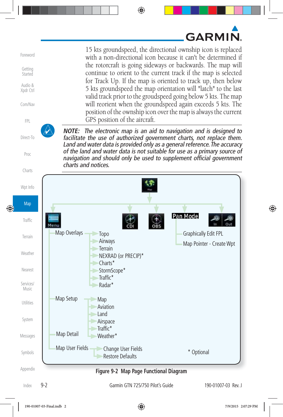
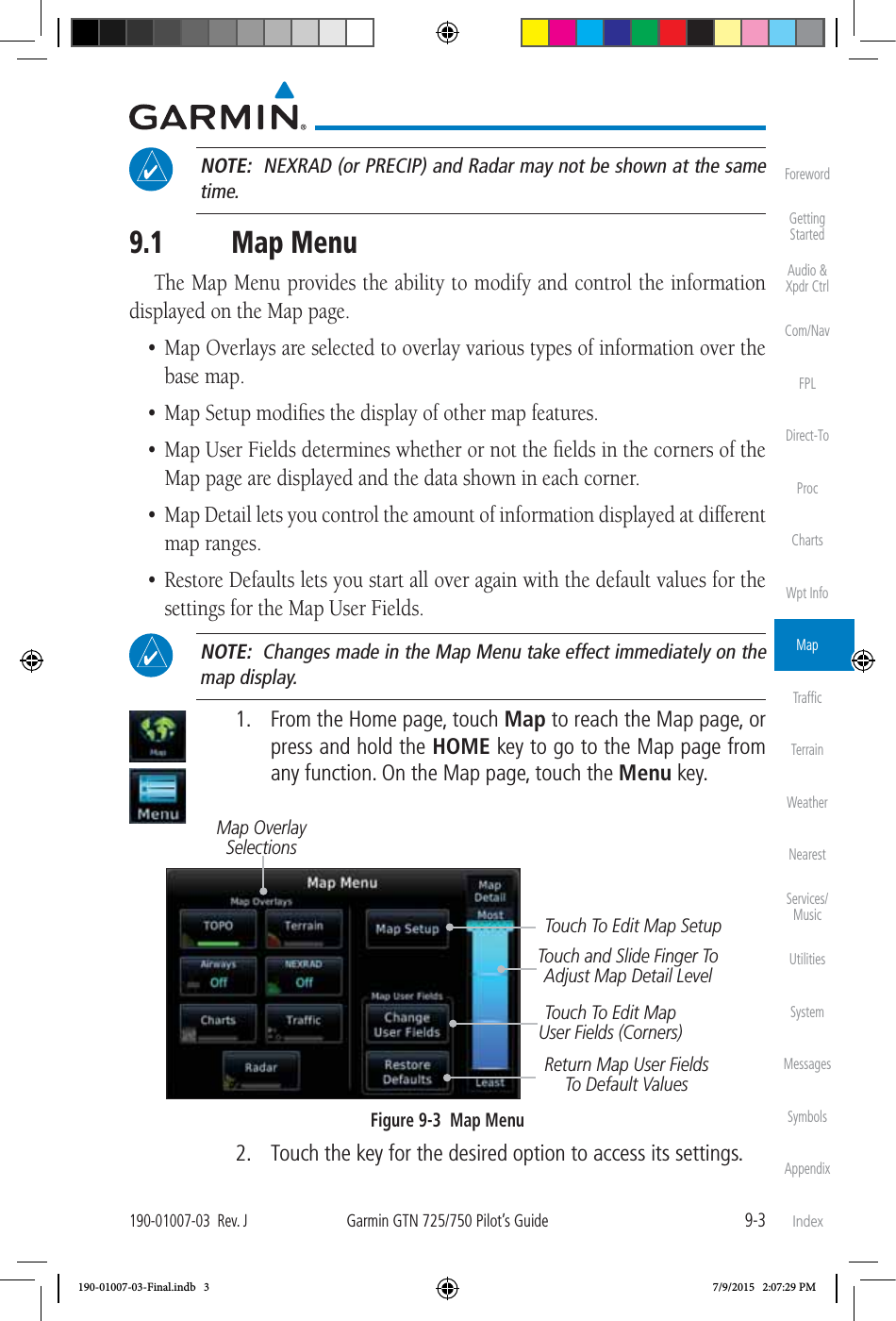
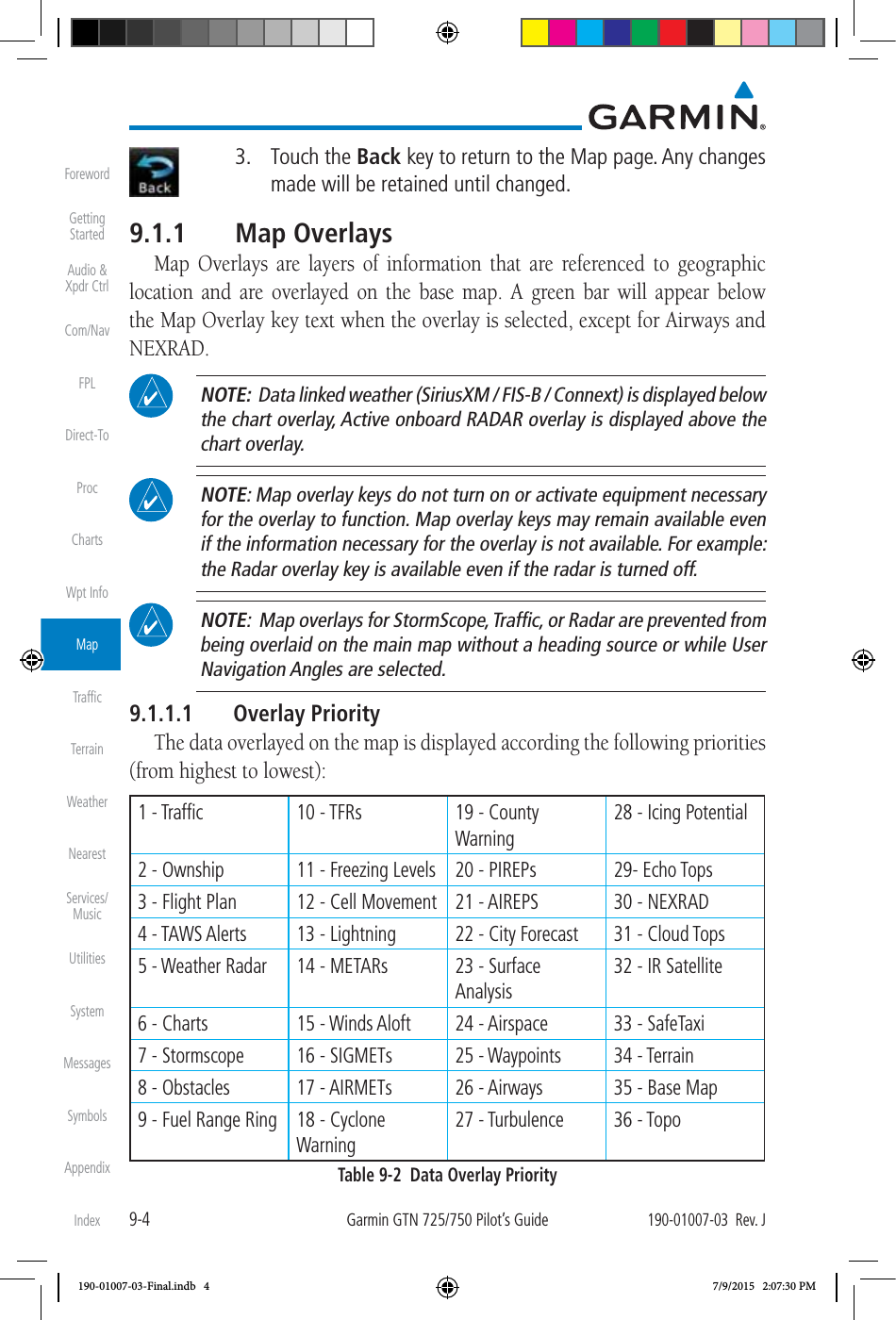
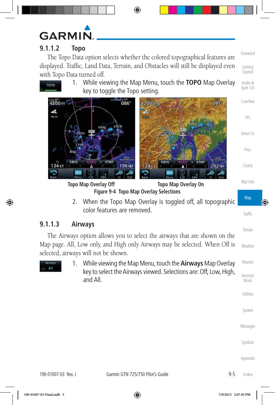
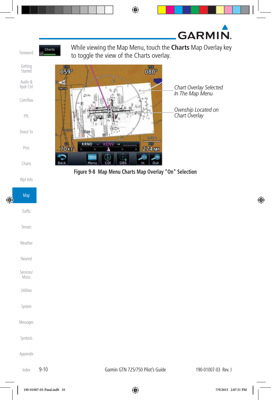
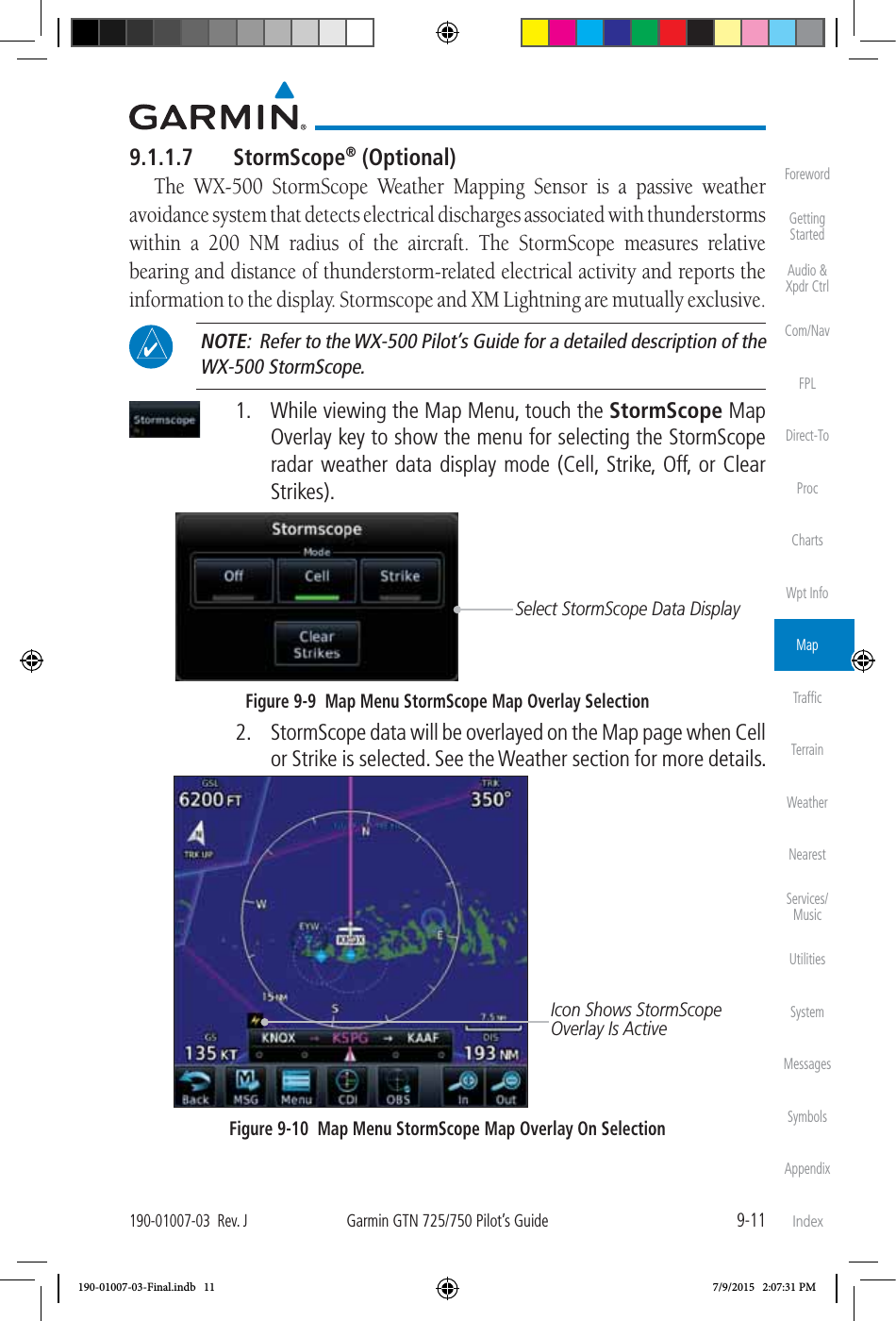
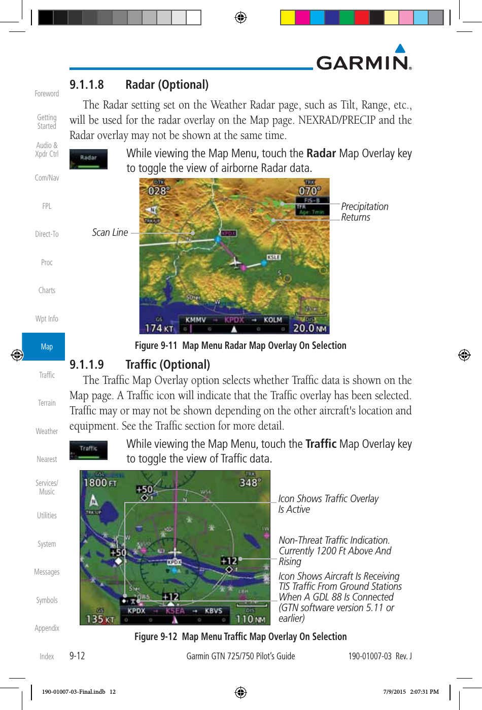
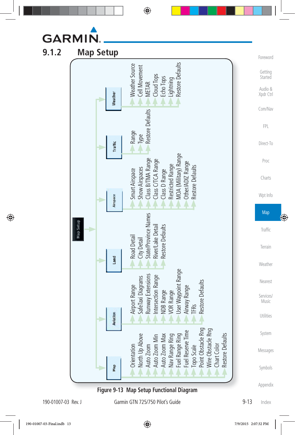
User Manual
Discussion / Help
Navigation