Garmin 0163700 Spread Spectrum Digital Transmission 2402-2480 MHz User Manual
Garmin International Inc Spread Spectrum Digital Transmission 2402-2480 MHz
UserManual.wiki
>
Garmin
>
0163700 User Manual
>
User Manual 3
Contents
1.
User Manual
2.
User Manual 1
3.
User Manual 2
4.
User Manual 3
5.
Users Manual
6.
Users Manual 1
7.
Users Manual 2
8.
Users Manual 3
User Manual 3
Navigation menu
Upload a User Manual
Namespaces
Wiki Guide
HTML
PDF
Info
Views
User Manual
Discussion / Help
Navigation
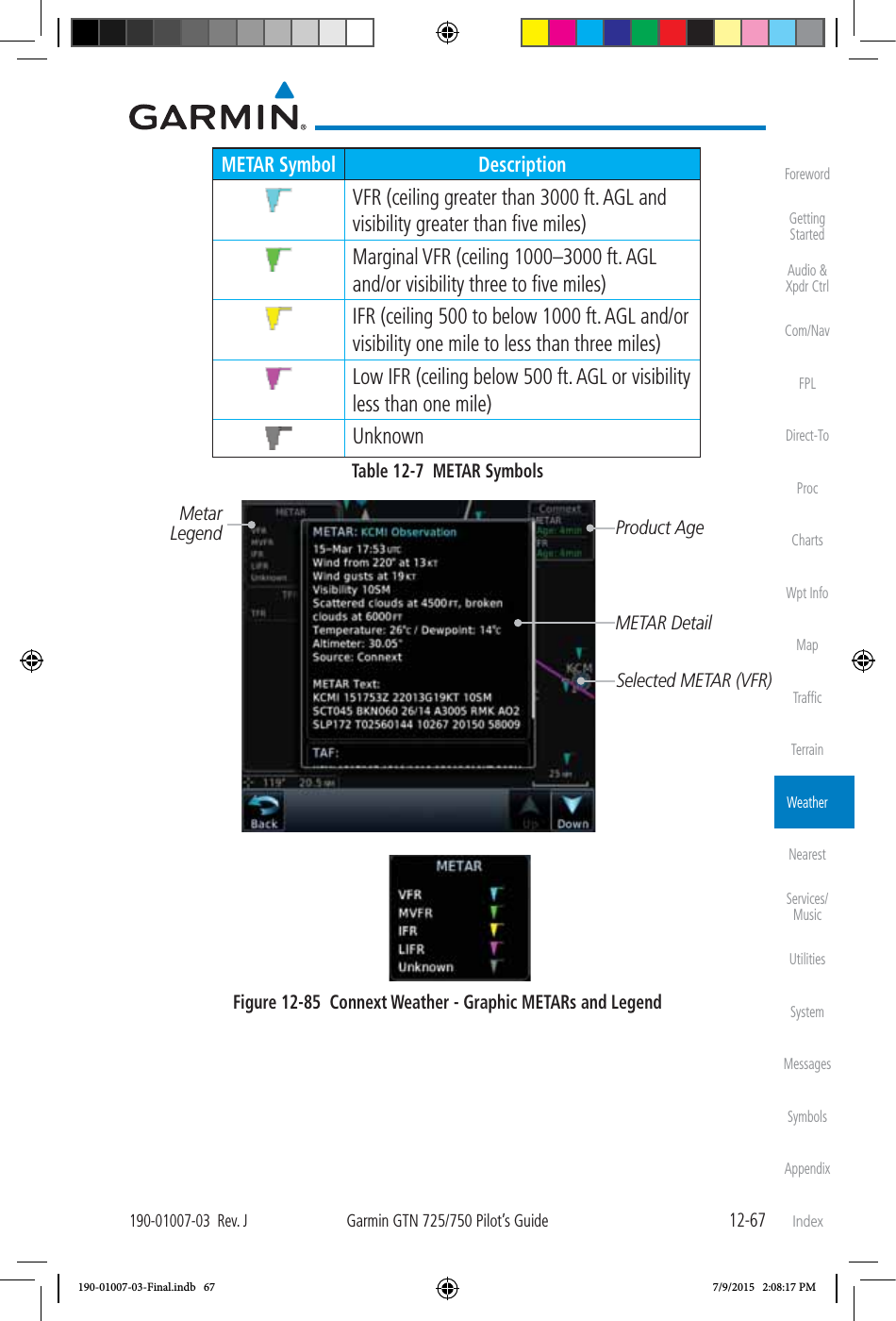

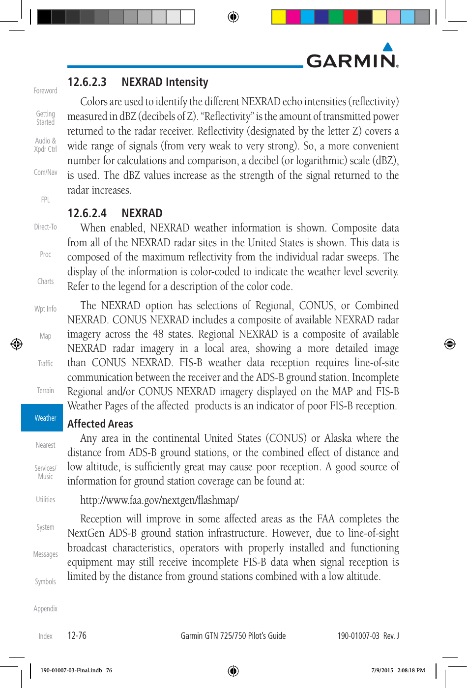
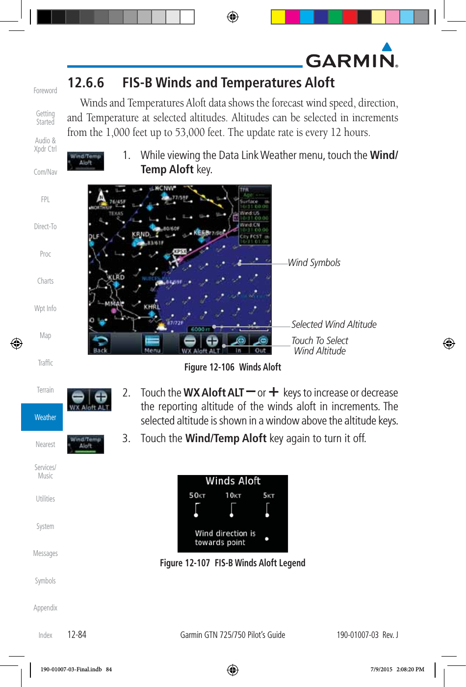
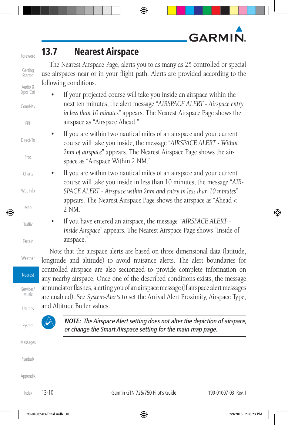
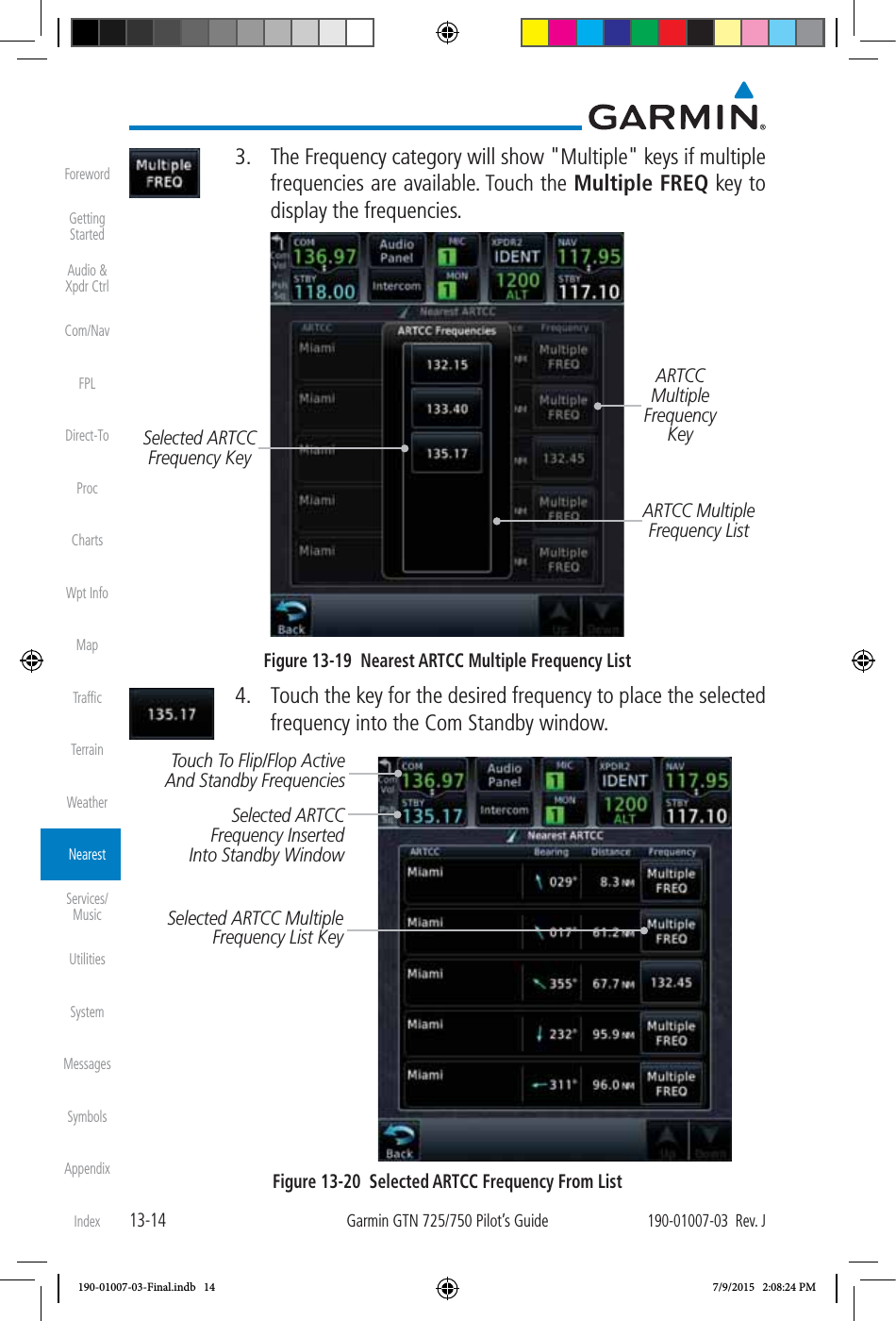
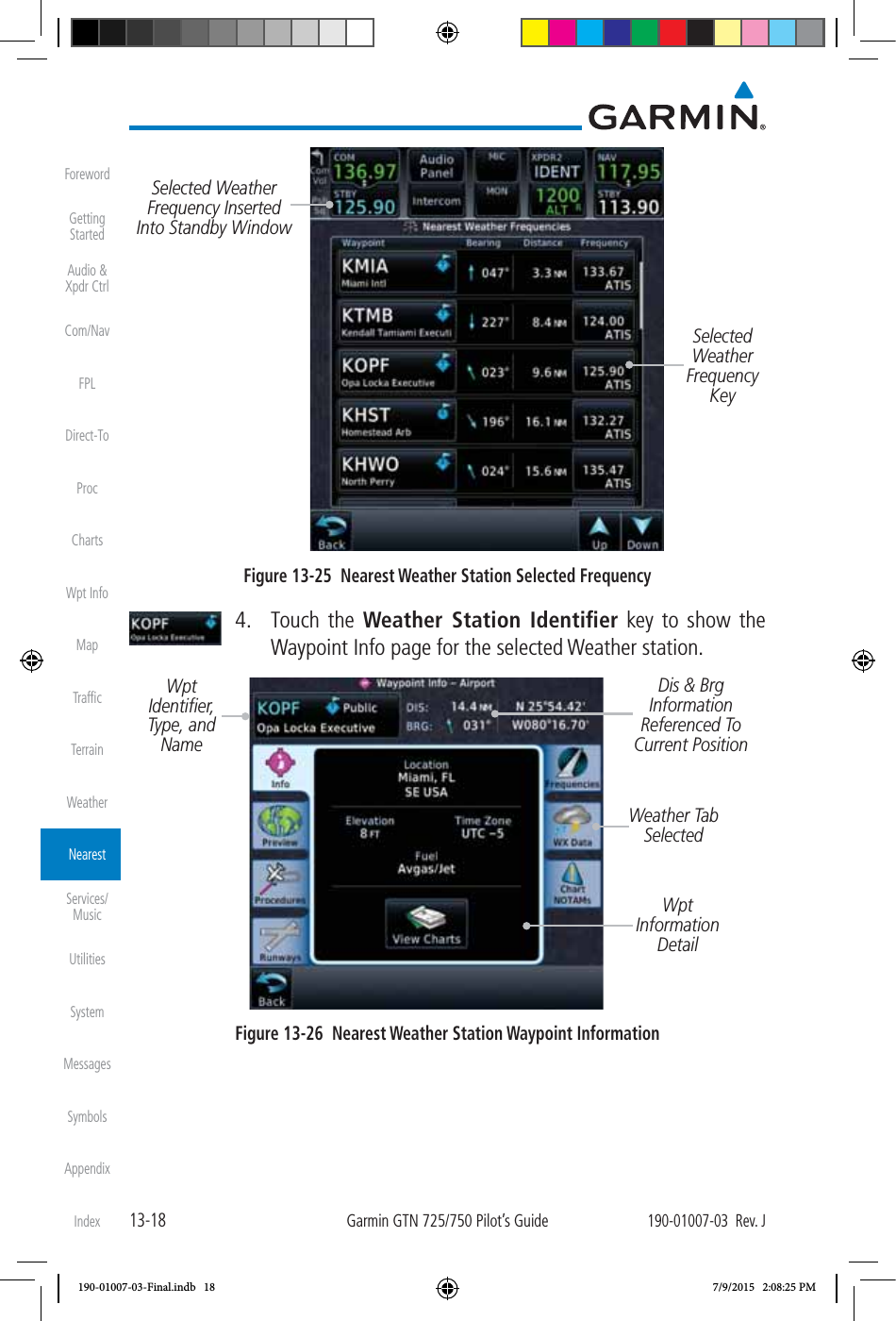
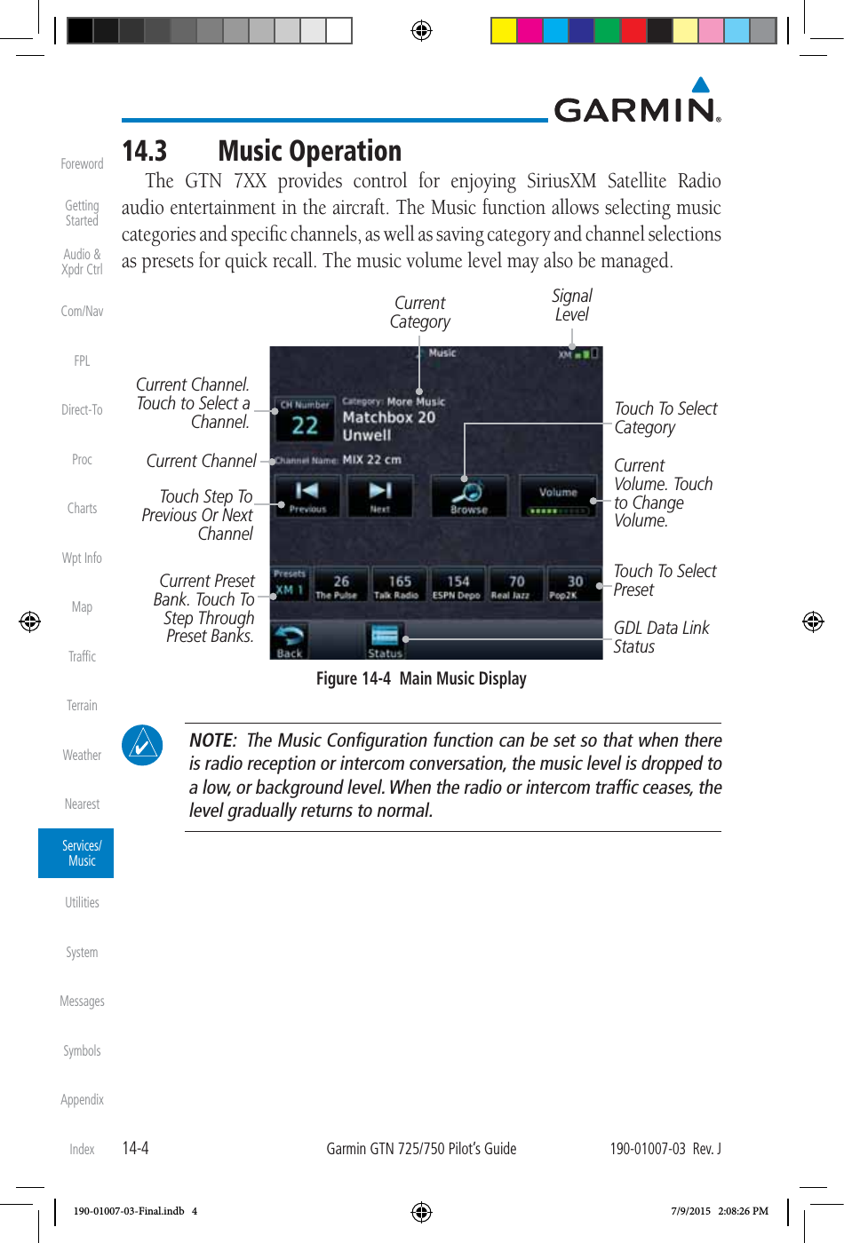

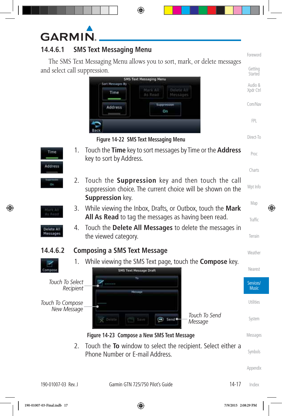
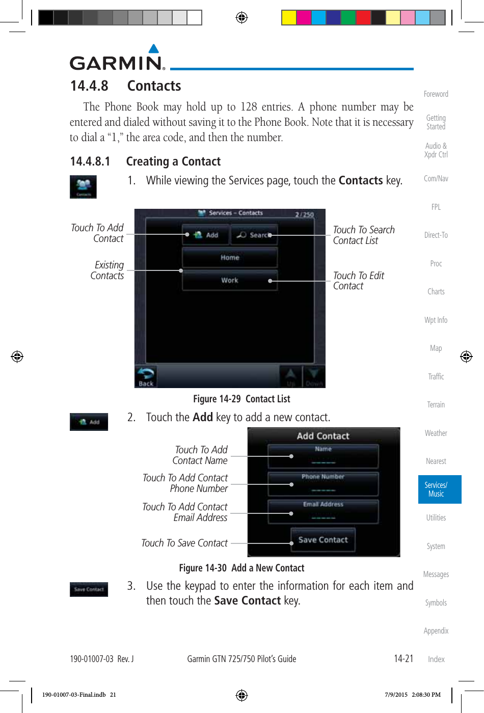
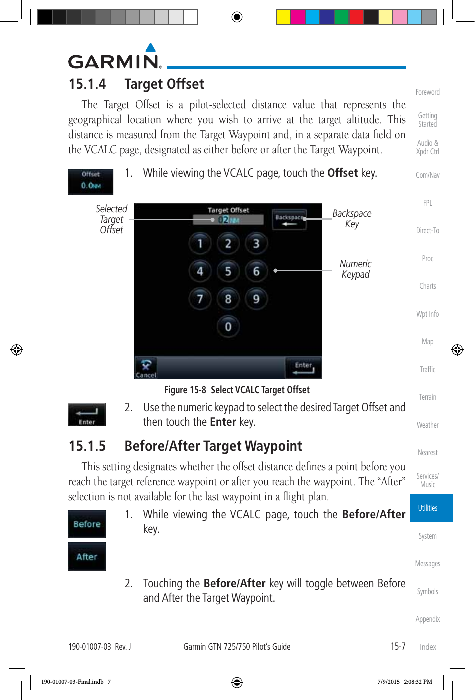
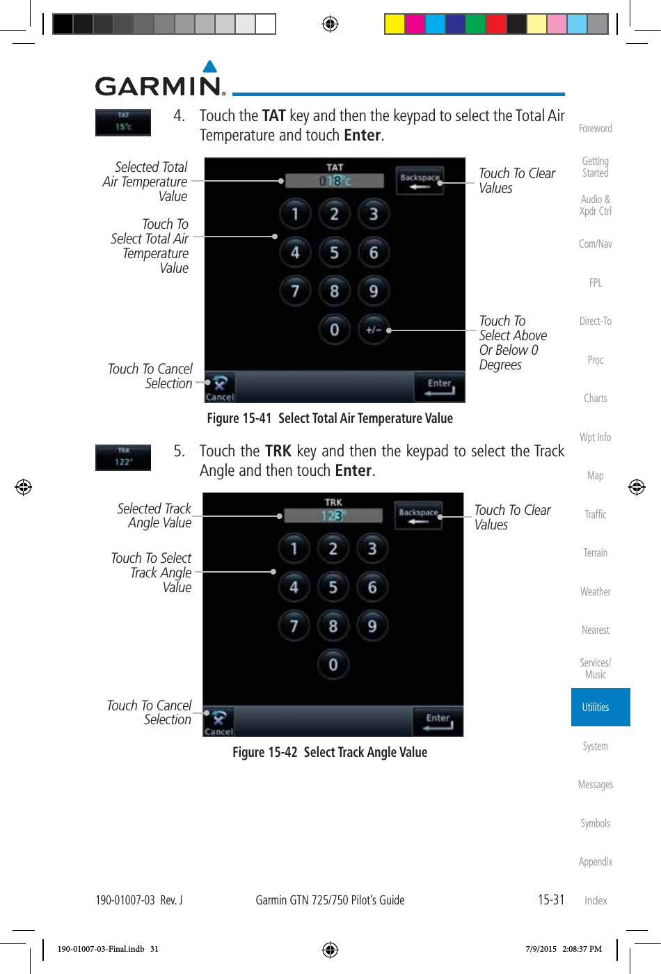
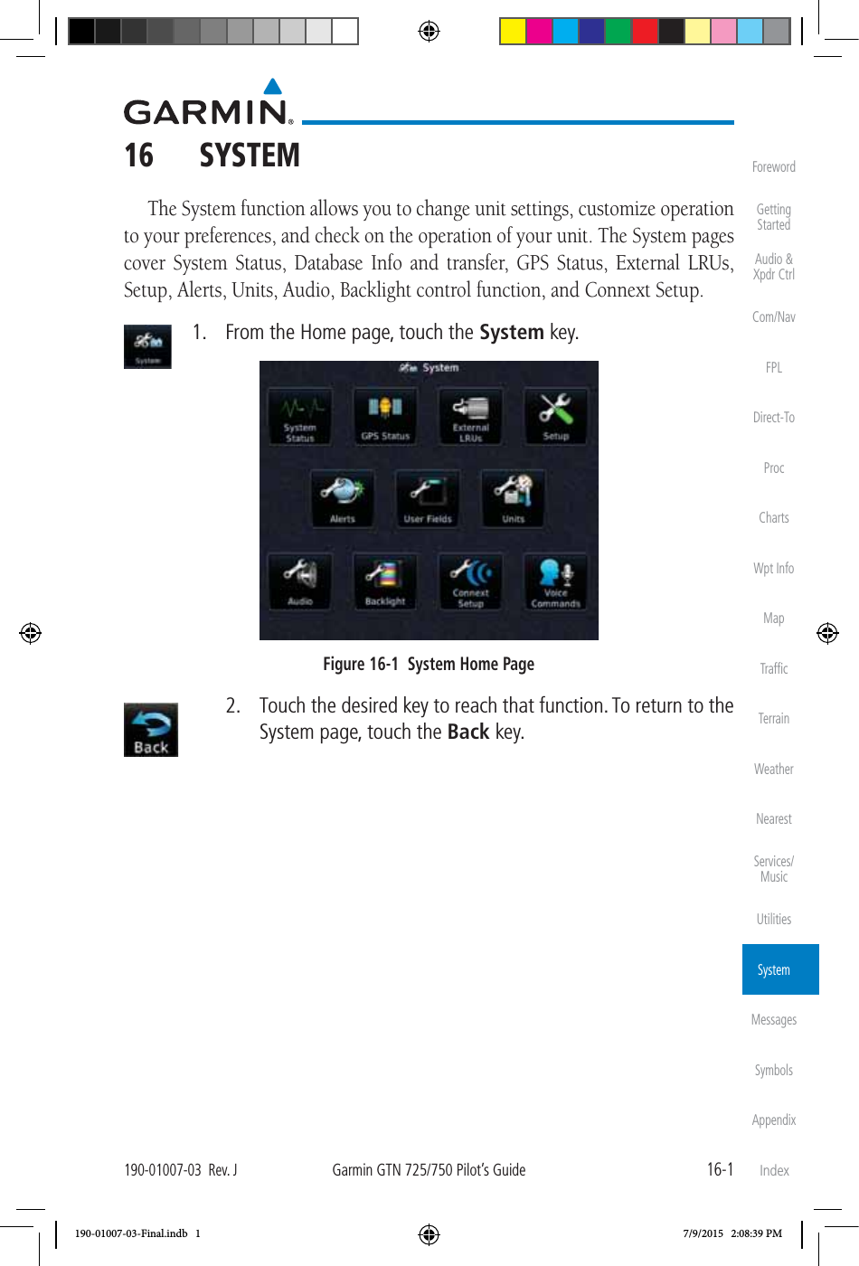
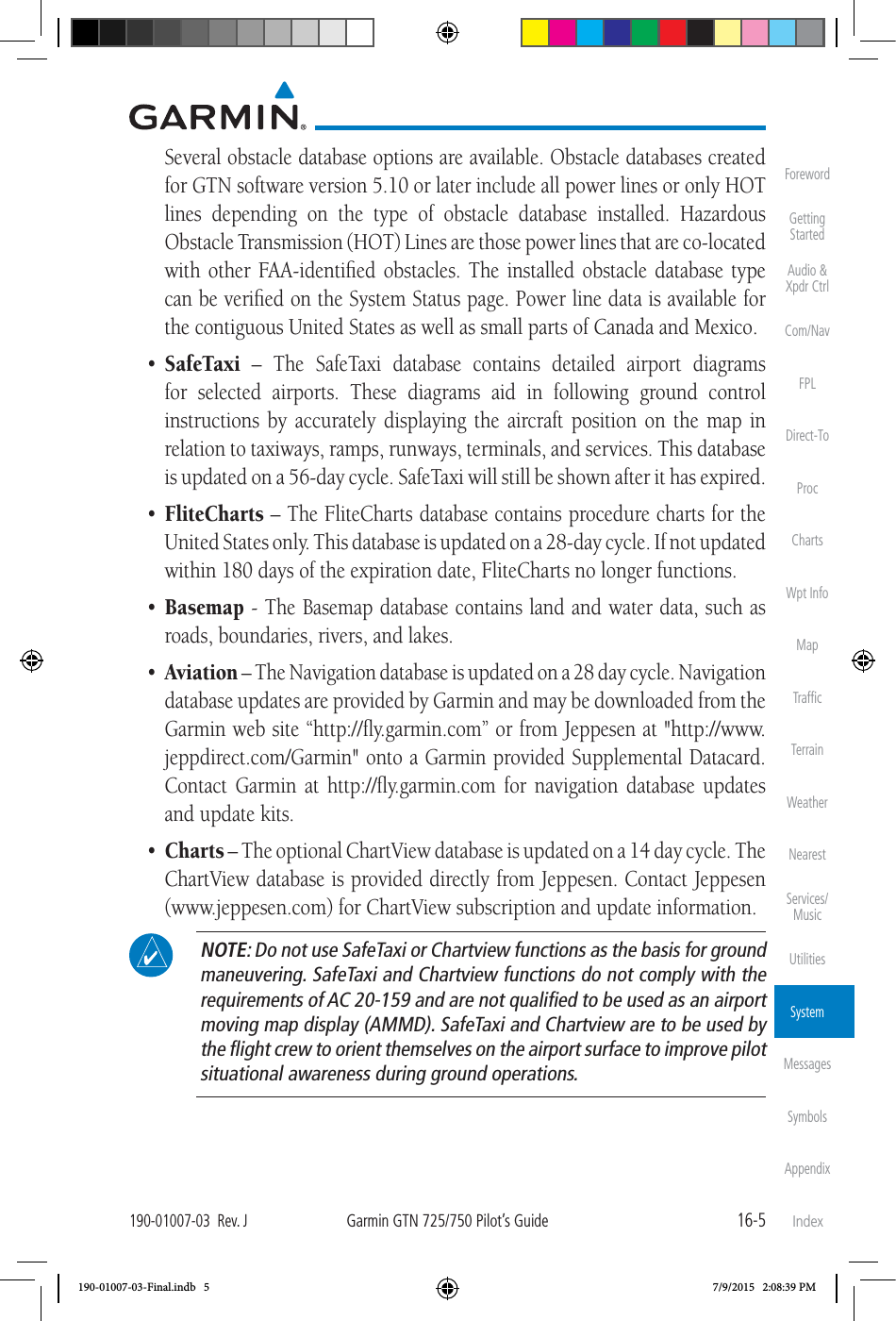
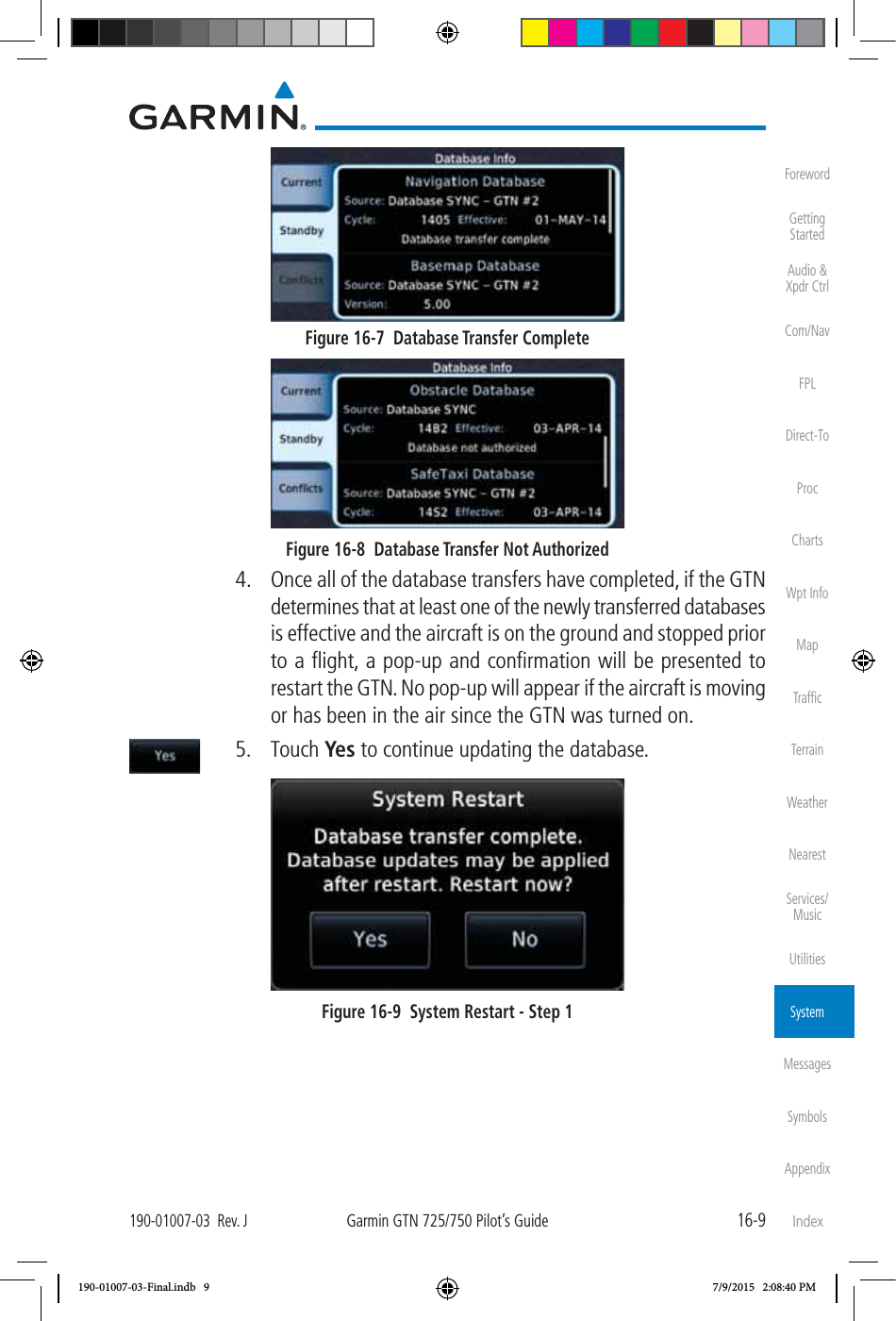
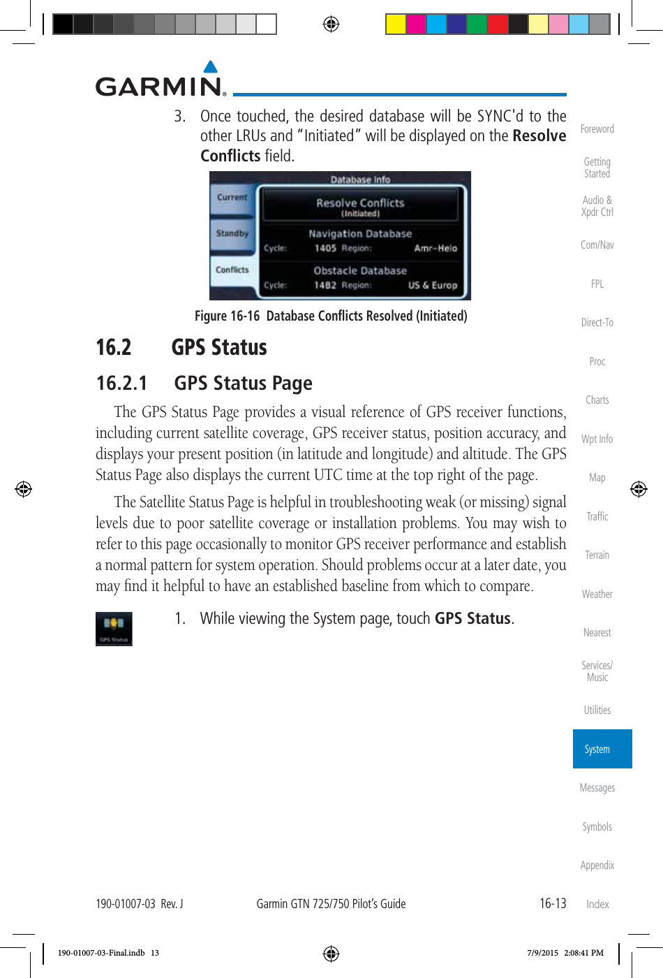
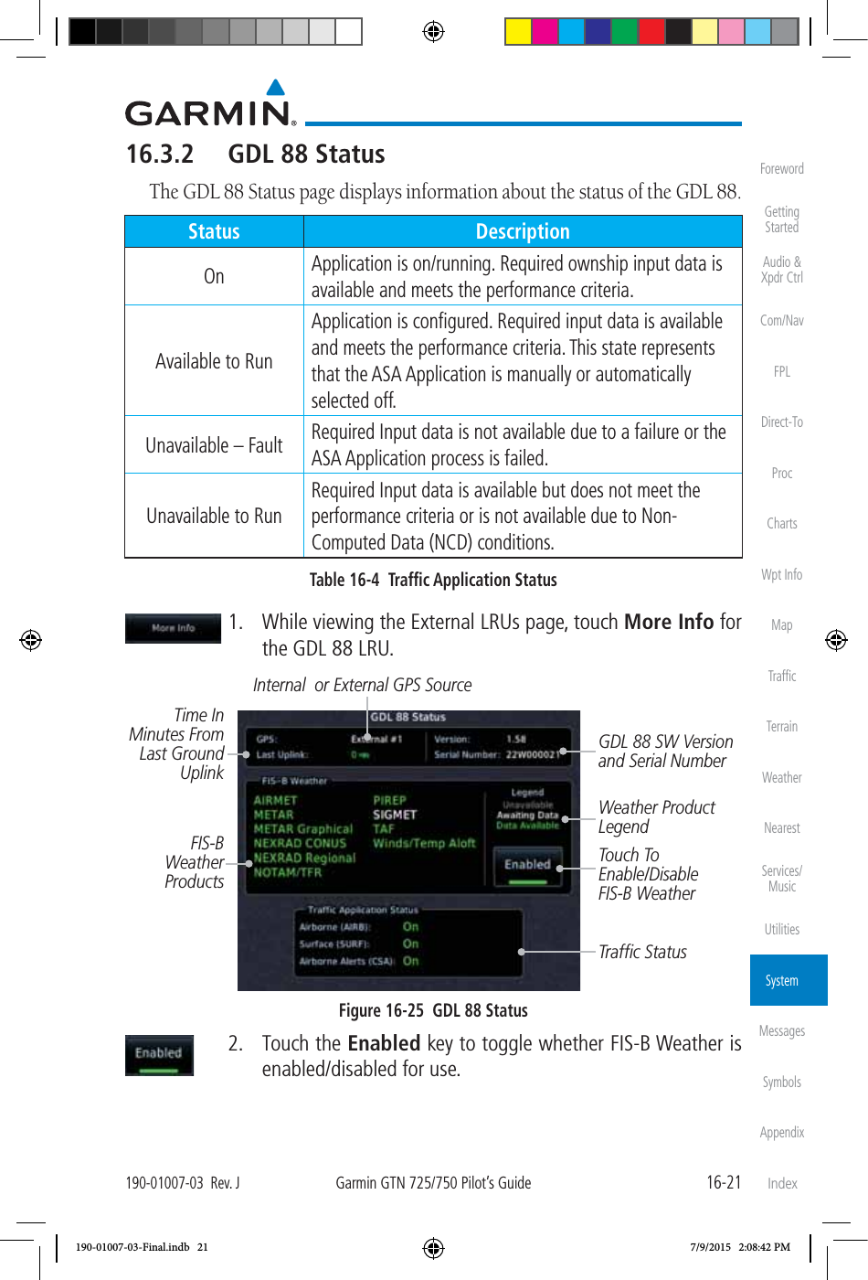
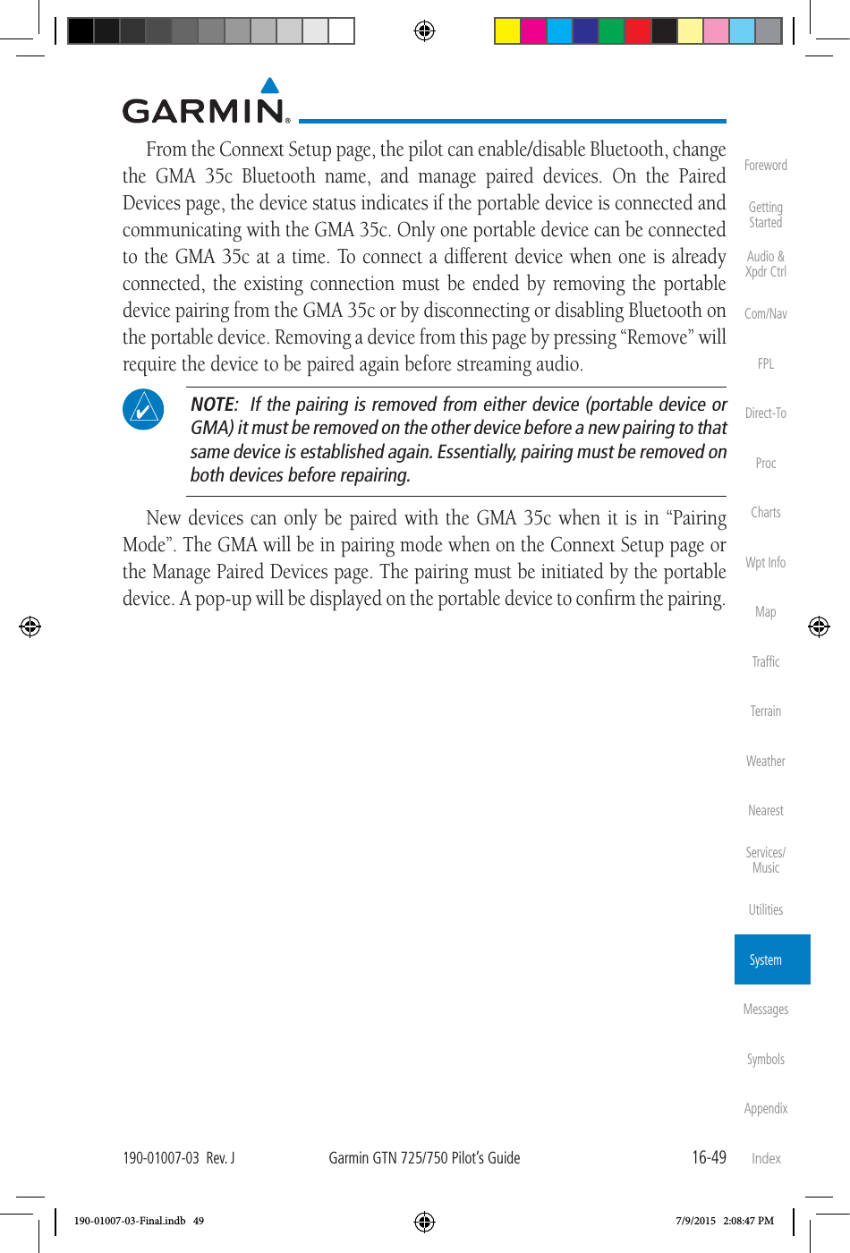
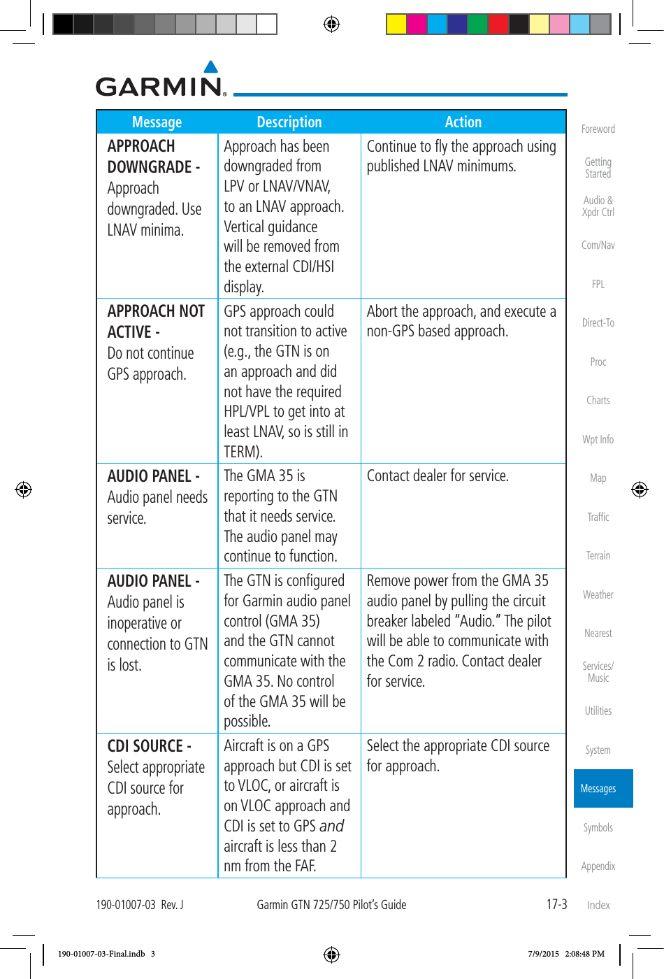
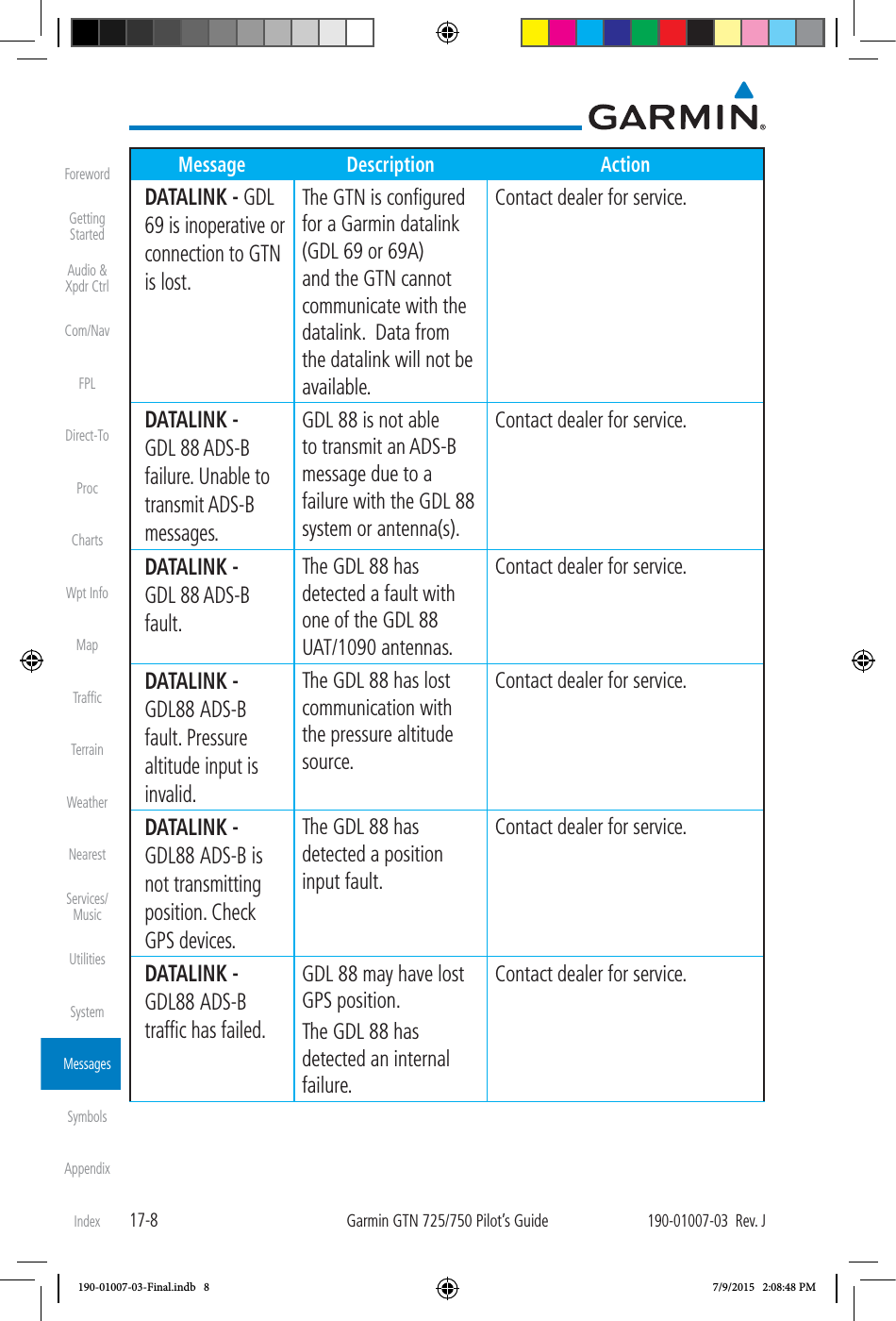
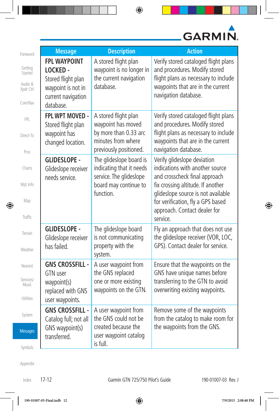
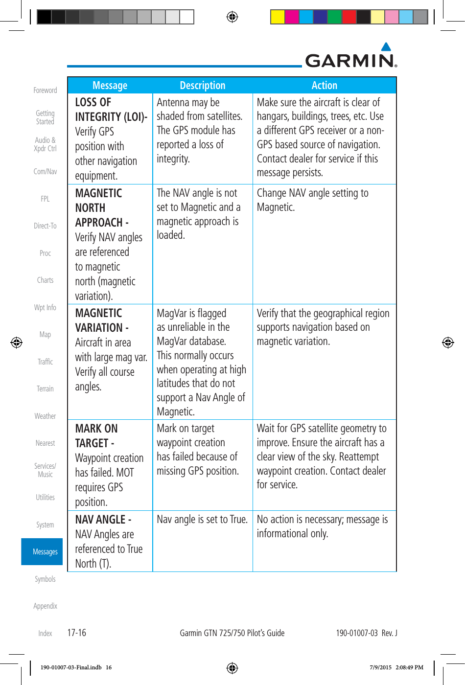
![17-6Garmin GTN 725/750 Pilot’s Guide190-01007-03 Rev. JForewordGetting StartedAudio & Xpdr CtrlCom/NavFPLDirect-ToProcChartsWpt InfoMapTrafficTerrainWeatherNearestServices/ MusicUtilitiesSystemMessagesSymbolsAppendixIndexMessage Description ActionCROSSFILL ERROR - GTN software mismatch. See CRG for crossfilled items. Crossfill is configured “on” but is not working due to software mismatch. See section 16.4.1.4 for a list of crossfilled items that will no longer be crossfilled. Contact dealer to have software versions updated. CROSSFILL ERROR - GTN Navigation DB mismatch. See CRG for crossfilled items. The navigation databases do not match between GTNs resulting in a loss of communication between two units. Check the specified database version of both GTNs and ensure it is up-to-date. Update the specified database if needed. CROSSFILL STATUS - Crossfill is turned off. Crossfill is turned off. No action. DATABASE - Chart function unavailable. The GTN is configured for ChartView or FliteCharts and chart verification has failed. Contact dealer for service. DATABASE - Chart database valid until [DATE]. The GTN is configured for ChartView or FliteCharts and the chart database has or is about to expire. Verify chart database expiration date on the System – System Status page. Update chart database if necessary for operations. DATABASE - A procedure has been modified in a cataloged flight plan. A new database update caused a procedure to be truncated because the flight plan now has too many waypoints or removed a procedure because it no longer exists in the database. Verify stored cataloged flight plans and procedures. Modify stored flight plans and procedures as necessary to include the current procedures by re-loading those procedures to the stored flight plan routes. 190-01007-03-Final.indb 6 7/9/2015 2:08:48 PM](https://usermanual.wiki/Garmin/0163700.User-Manual-3/User-Guide-2814670-Page-157.png)
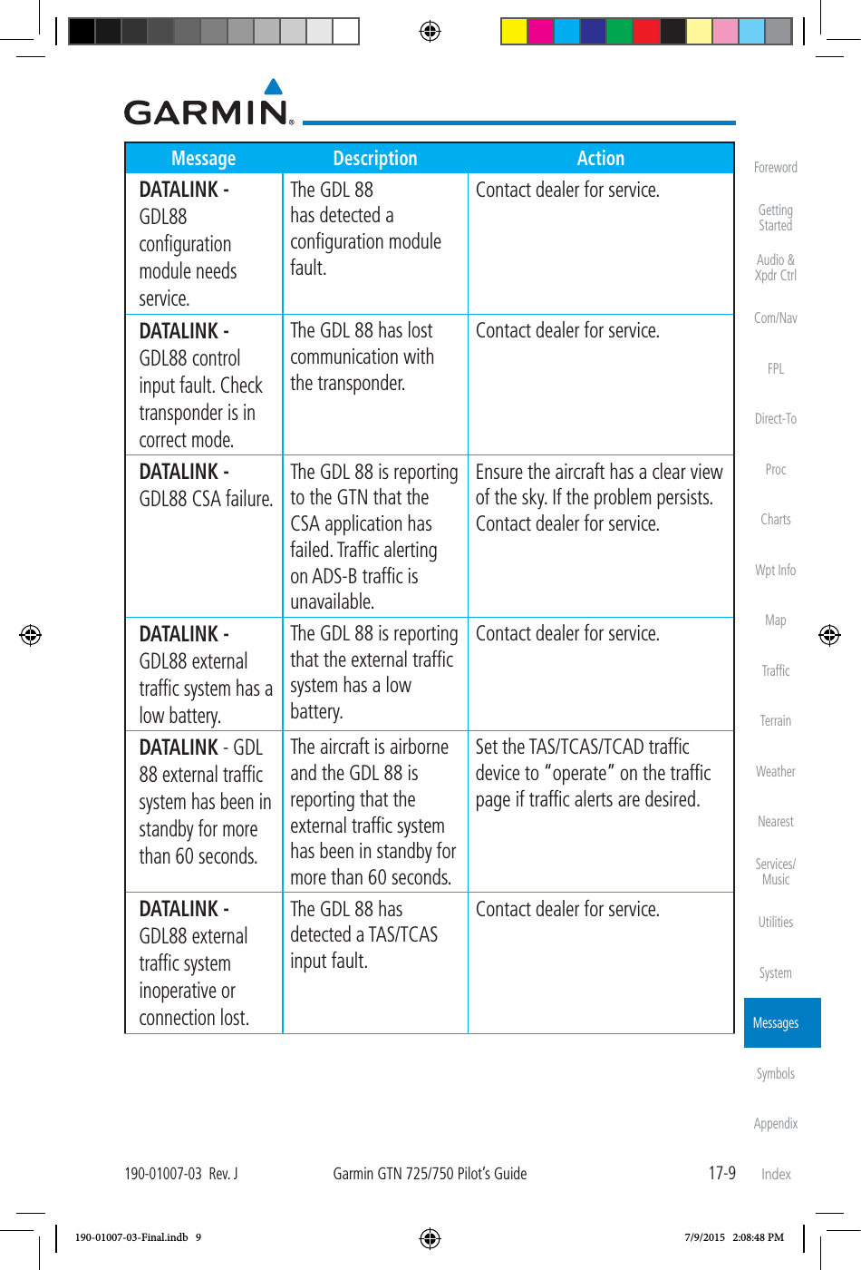
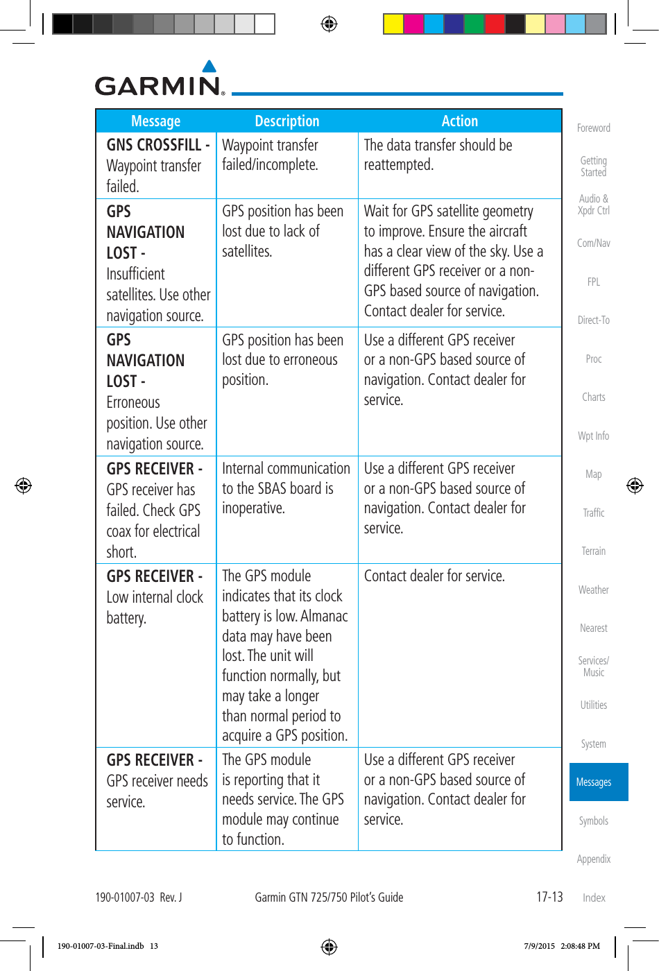
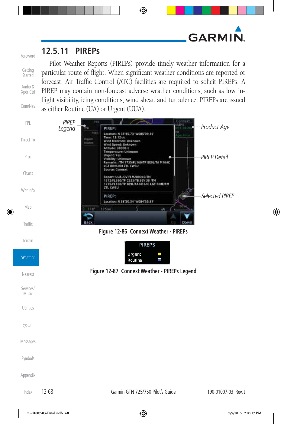
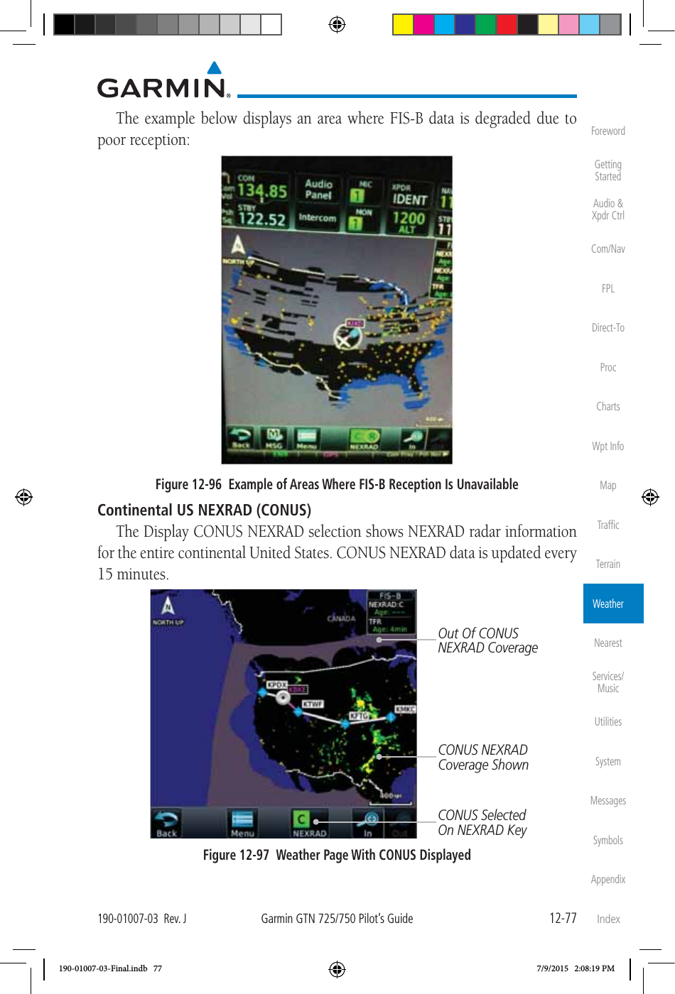
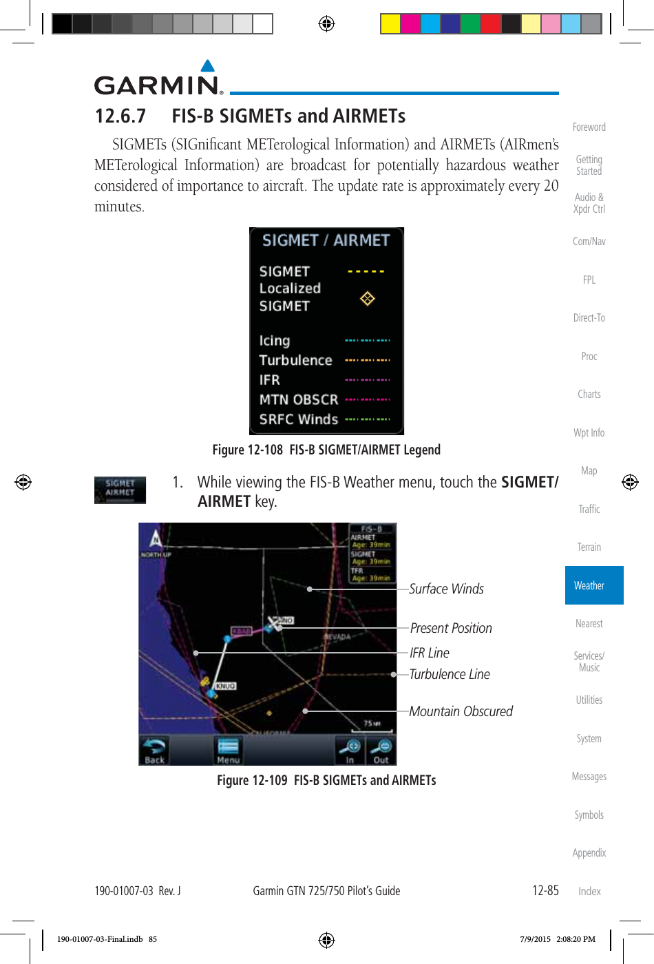
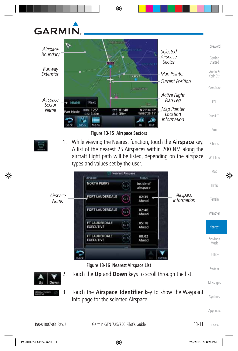
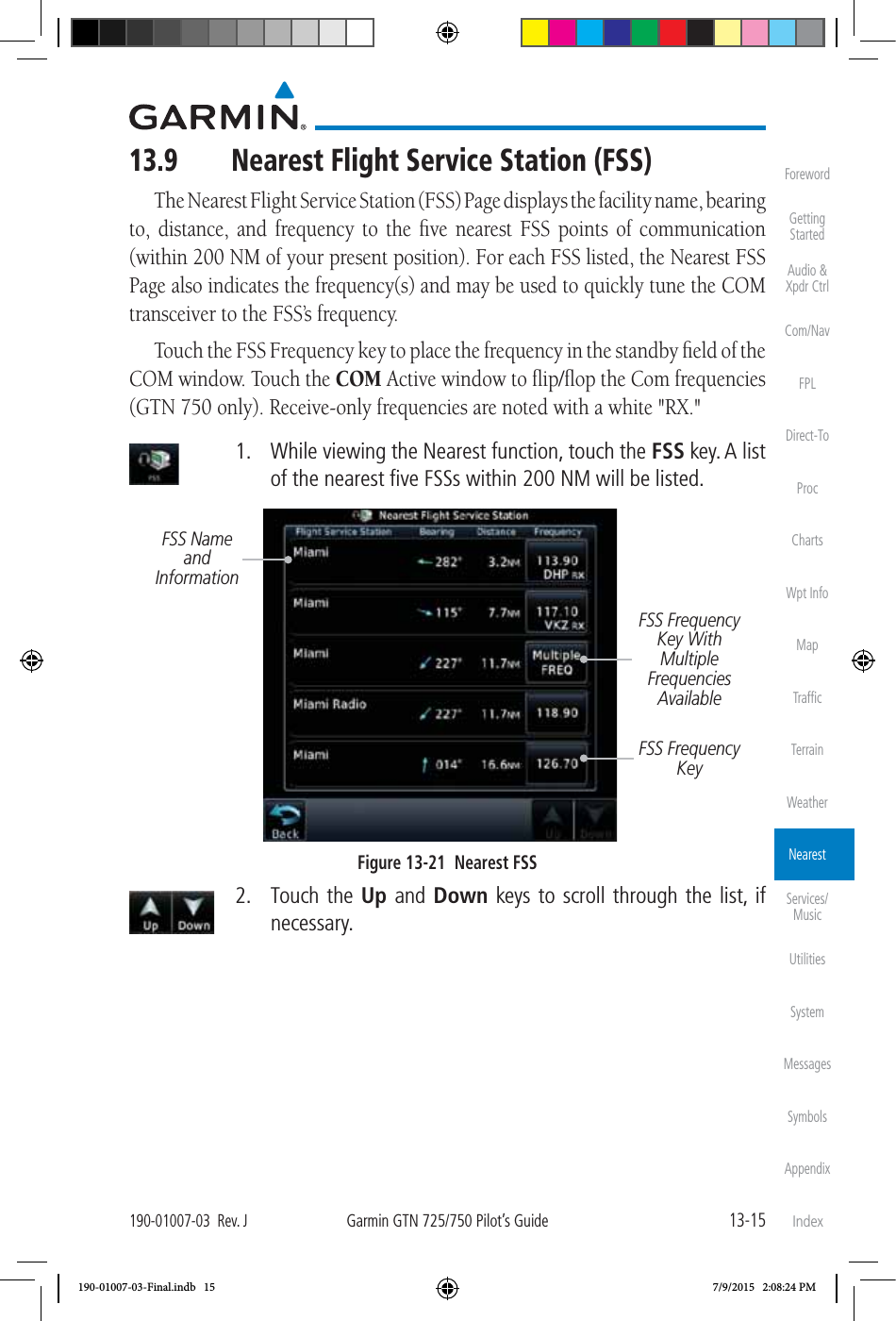
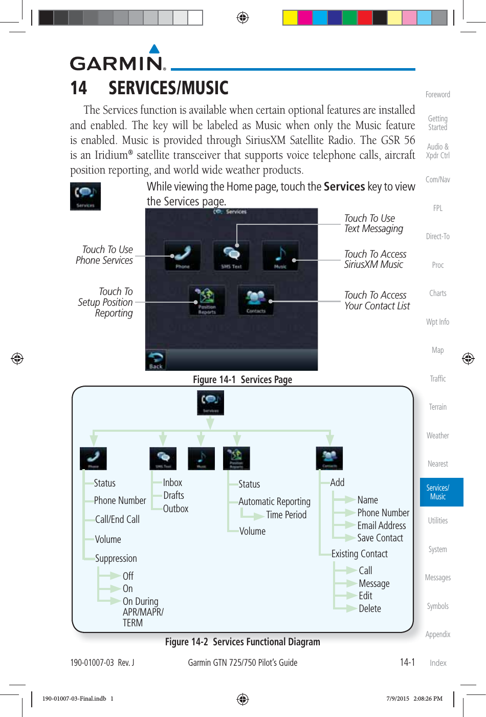
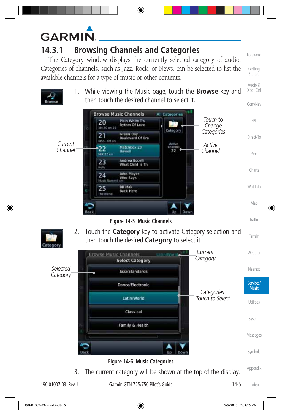
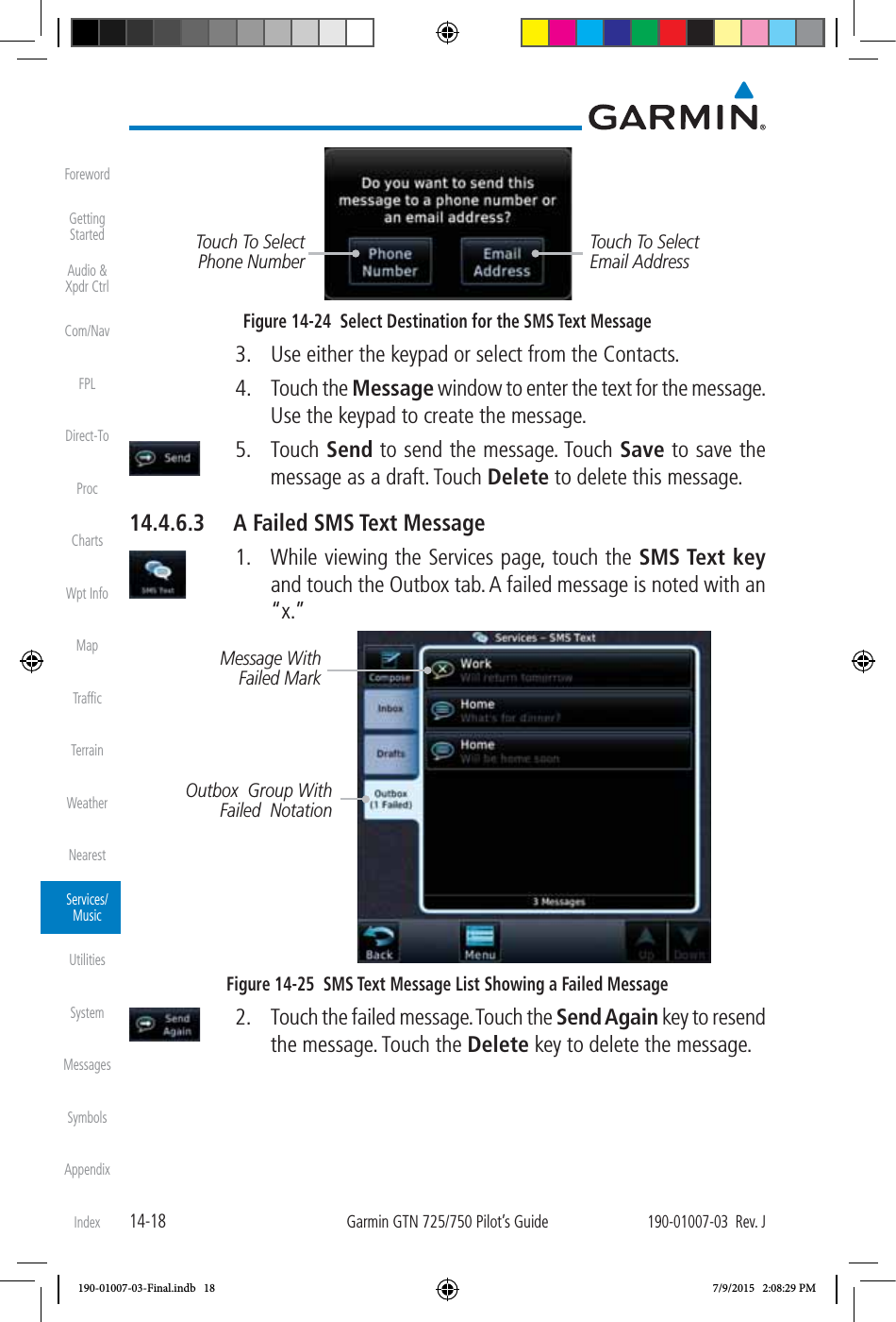
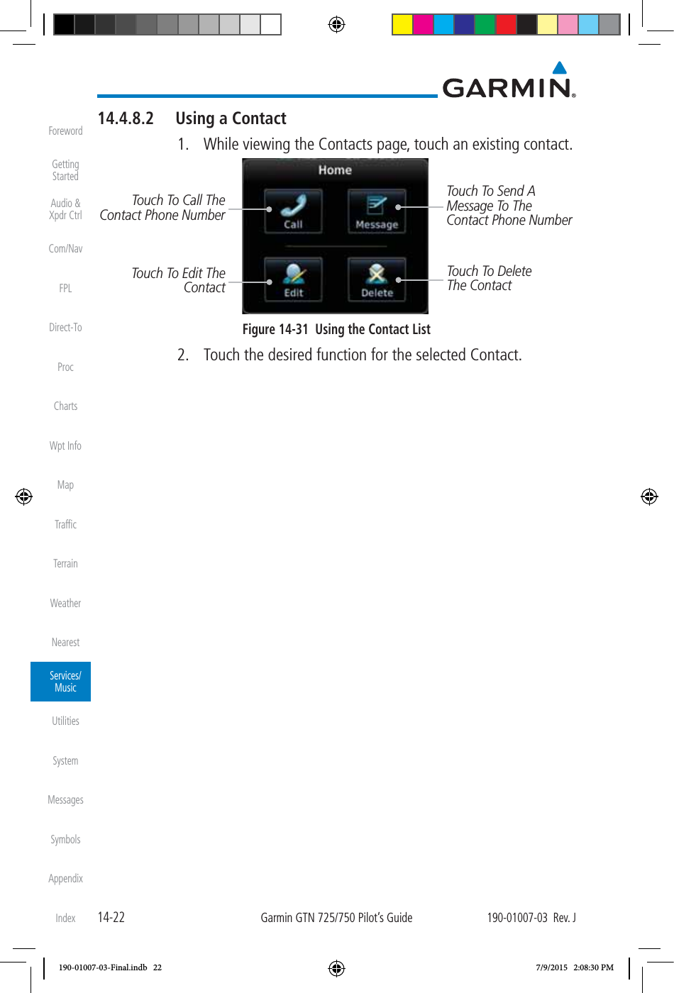
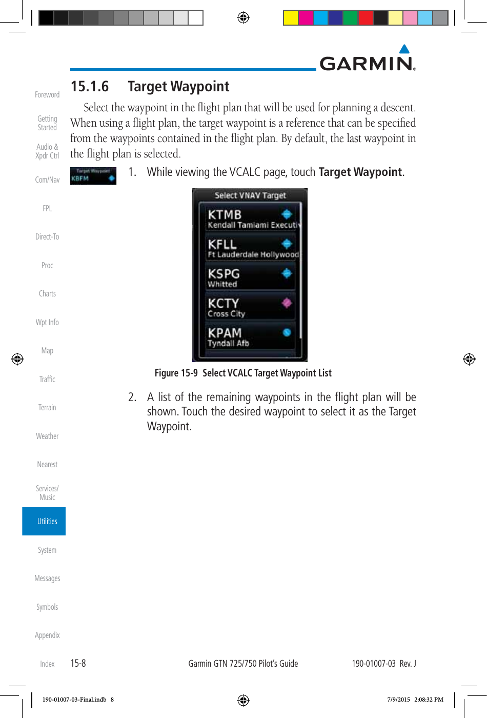
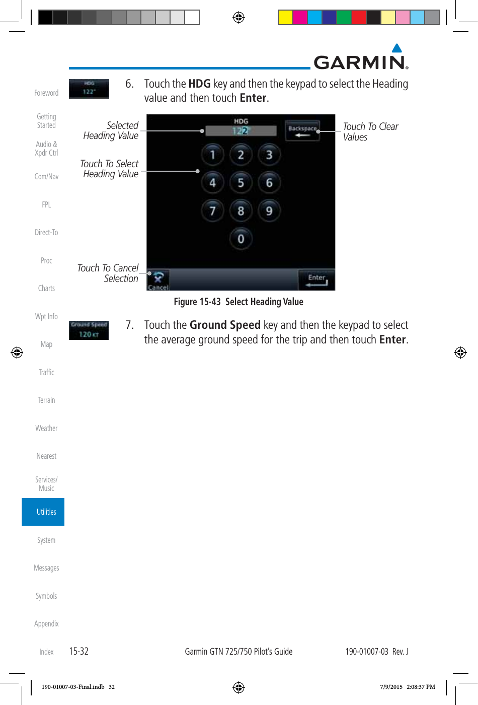
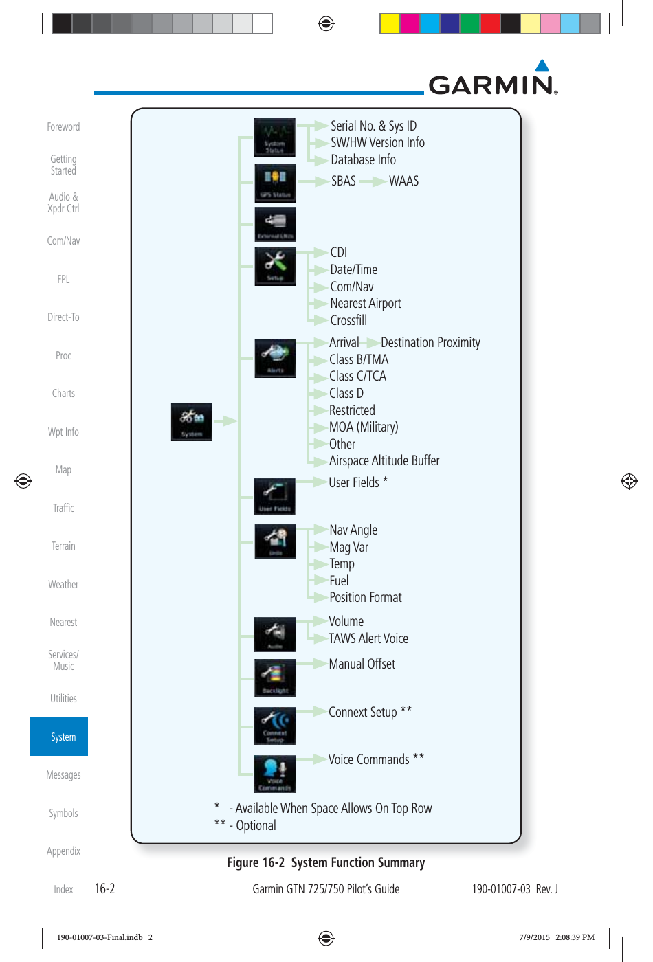
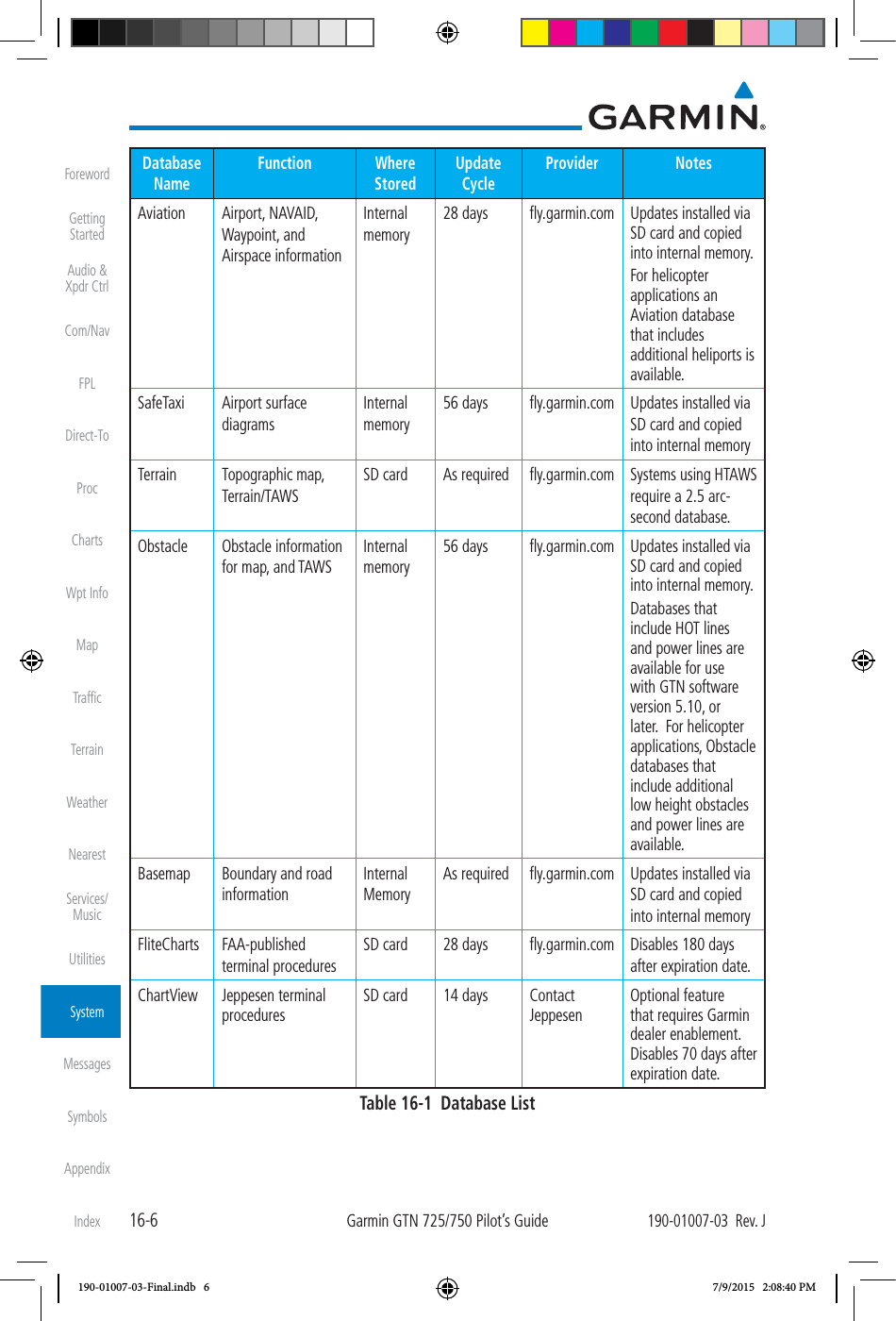
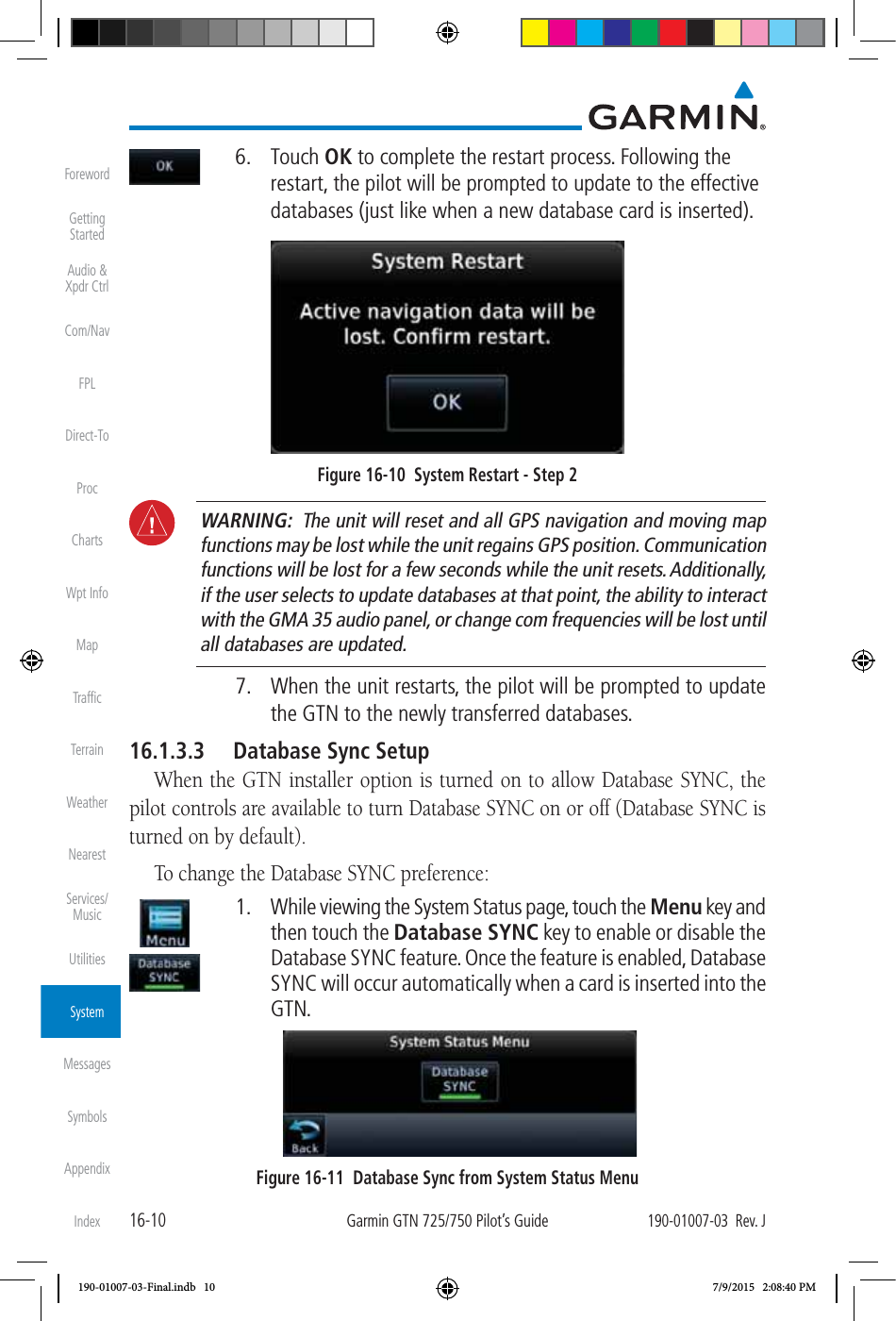
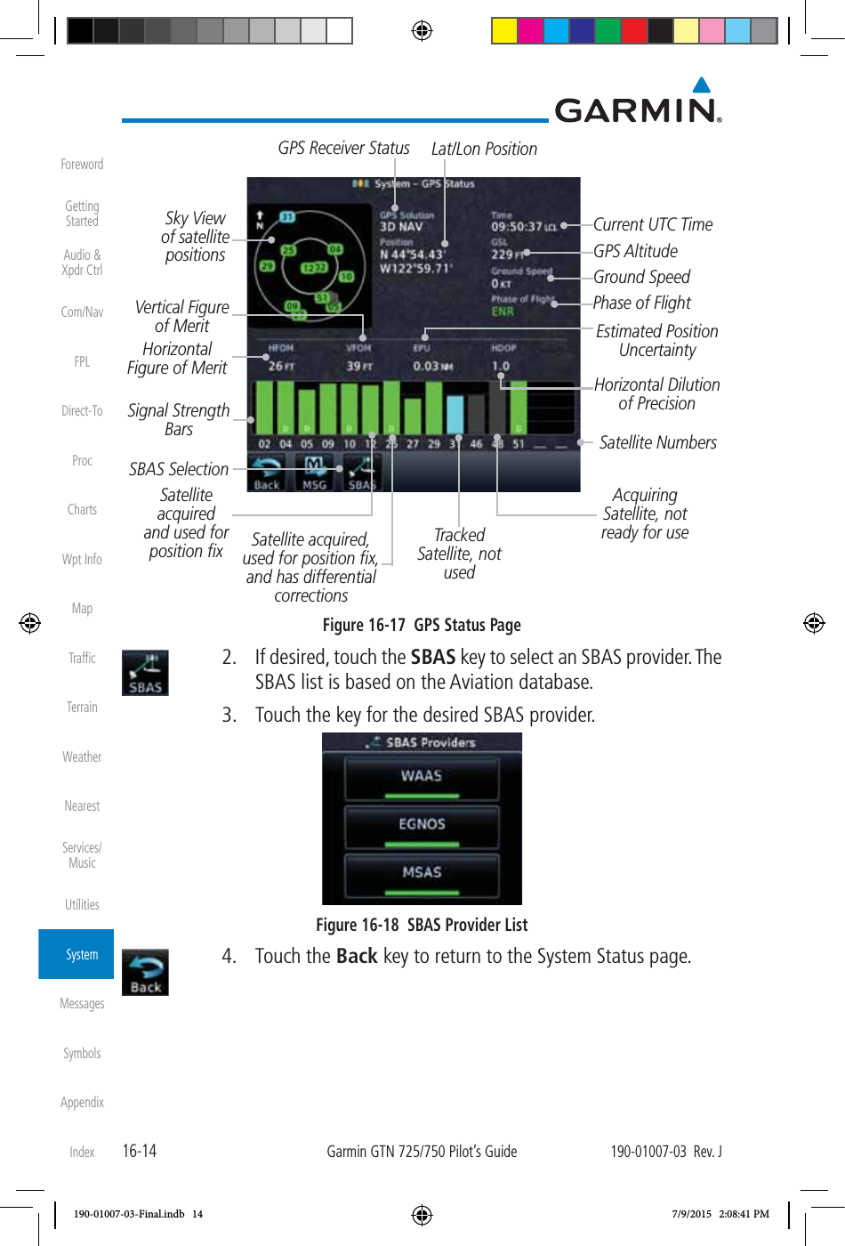
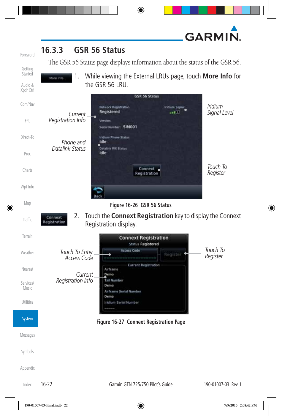
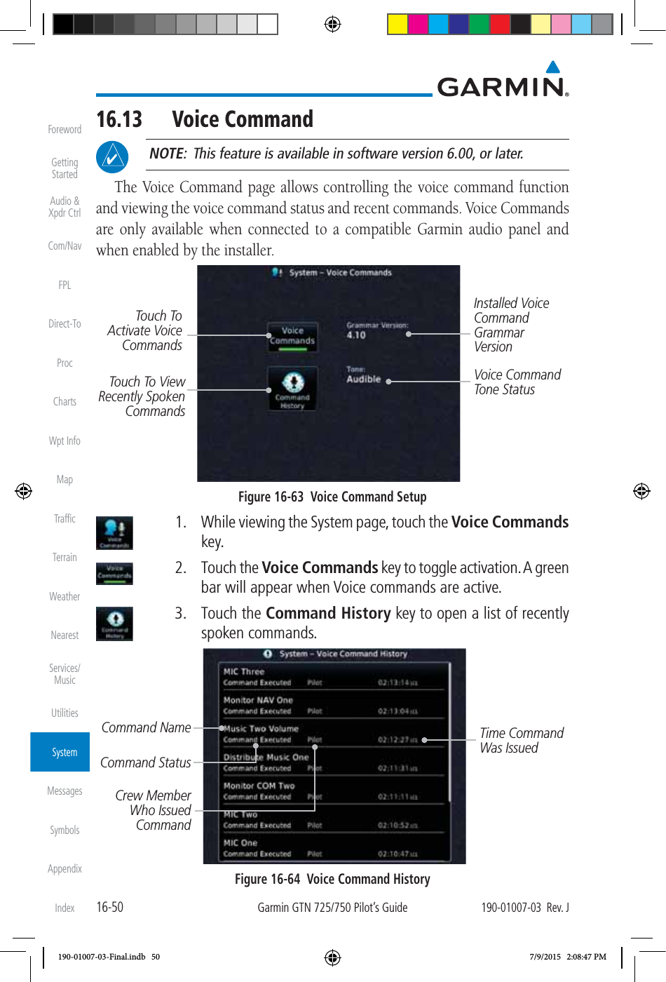
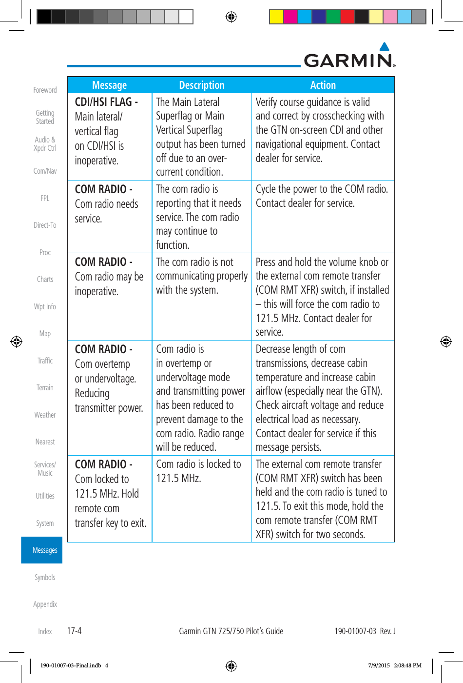
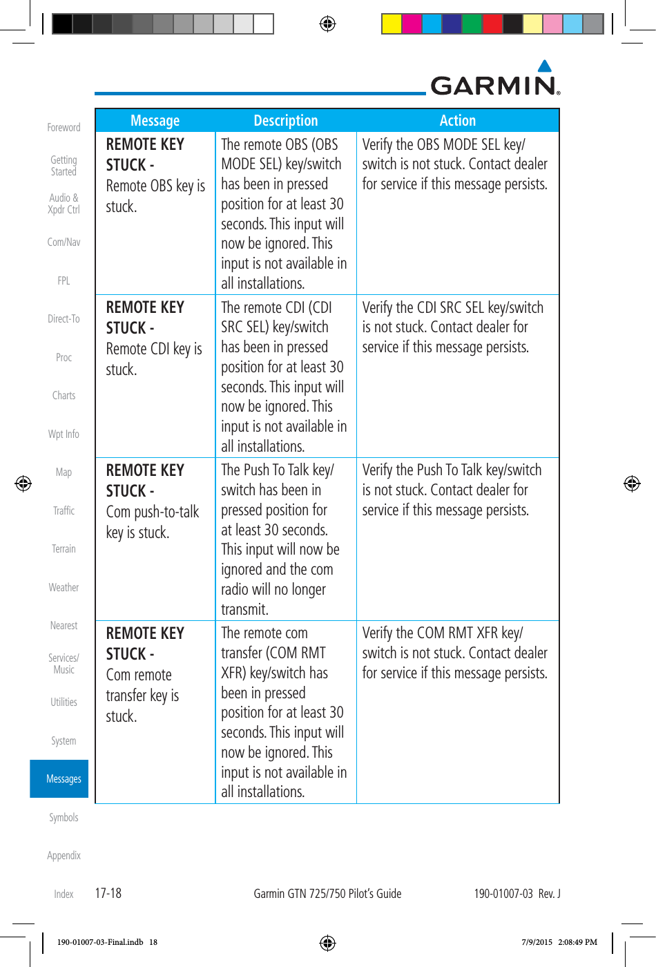
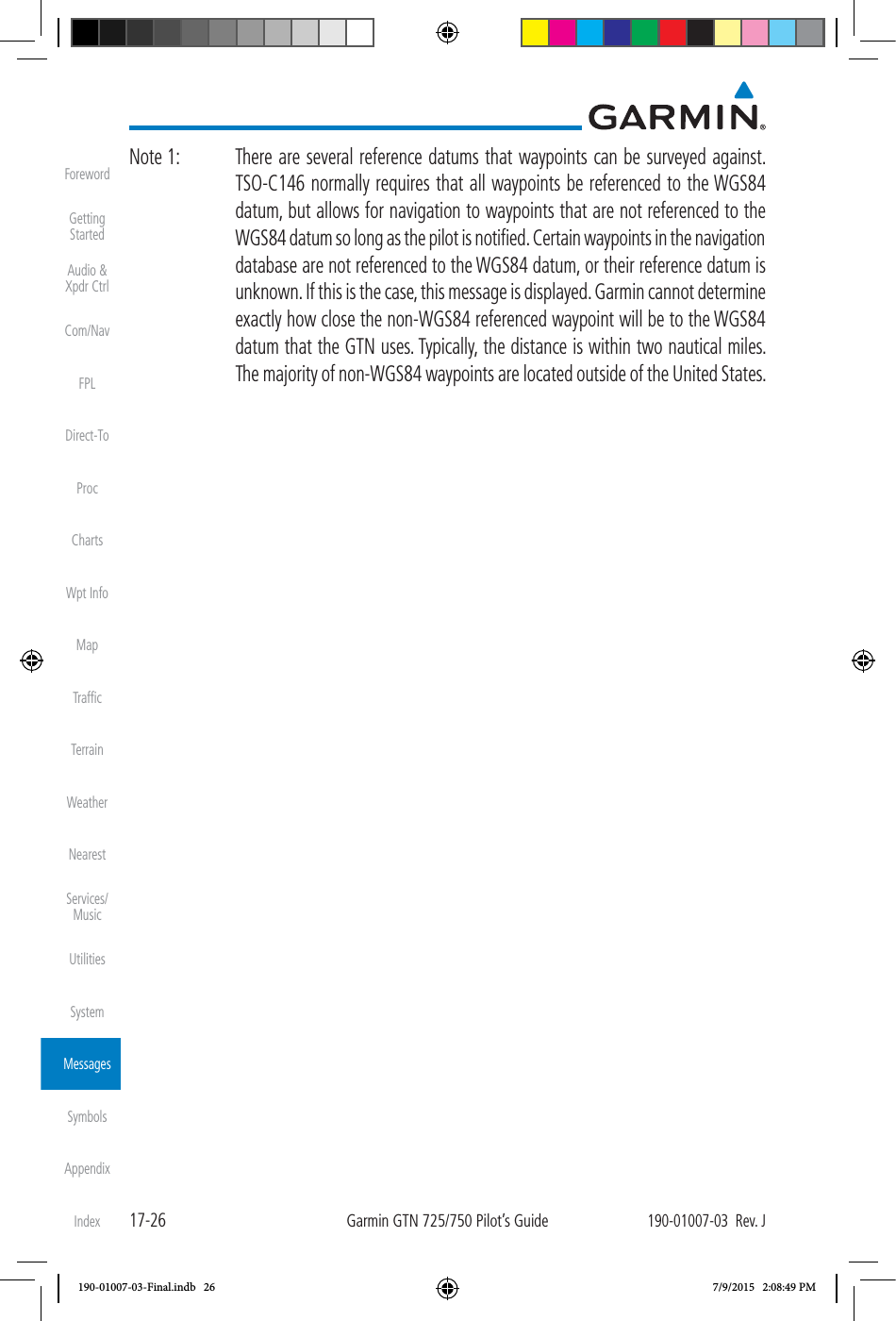
![17-17190-01007-03 Rev. JGarmin GTN 725/750 Pilot’s GuideForewordGetting StartedAudio & Xpdr CtrlCom/NavFPLDirect-ToProcChartsWpt InfoMapTrafficTerrainWeatherNearestServices/MusicUtilitiesSystemMessagesSymbolsAppendixIndexMessage Description ActionNAV ANGLE - NAV Angles are referenced to a User set value (U). Nav angle is set to User. No action is necessary; message is informational only. NON-WGS84 WAYPOINT - See CRG. Location may be different than where surveyed for [WPT].The active waypoint is not referenced to the WGS84 datum. See Note 1 at the end of the table. No action is necessary; message is informational only. OBS - OBS is not available due to dead reckoning or no active waypoint. OBS requires an active waypoint and is not supported in dead reckoning mode. No action is necessary; message is informational only. PARALLEL TRACK - Parallel track not supported past IAF. Parallel track is not supported on approaches. No action is necessary; message is informational only. PARALLEL TRACK - Parallel track not supported for turns greater than 120 degrees. Parallel track is not supported for turns greater than 120 degrees due to the acute angle. No action is necessary; message is informational only. PARALLEL TRACK - Parallel track not supported for leg type. Parallel track is not supported on current leg type. No action is necessary; message is informational only. 190-01007-03-Final.indb 17 7/9/2015 2:08:49 PM](https://usermanual.wiki/Garmin/0163700.User-Manual-3/User-Guide-2814670-Page-168.png)
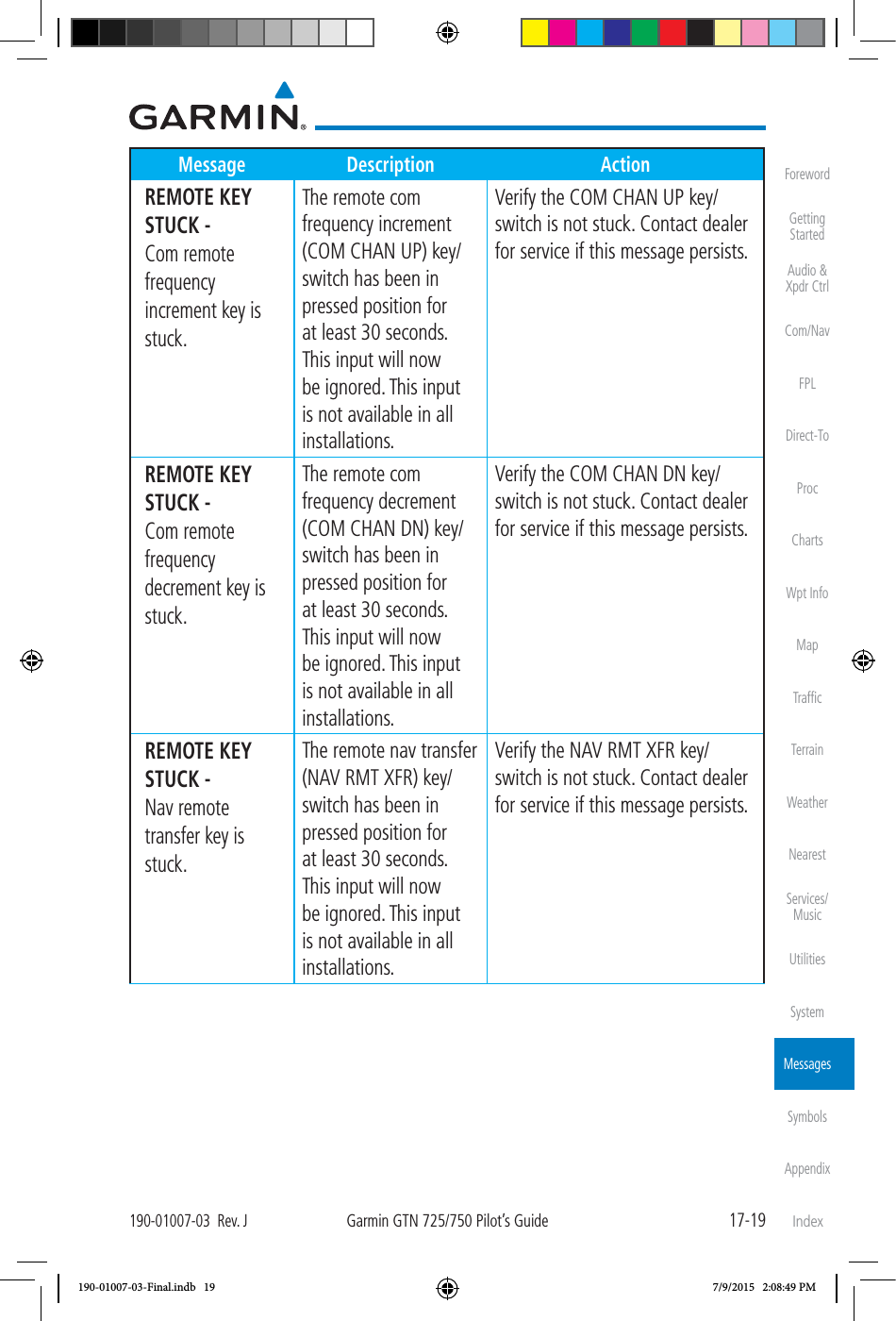
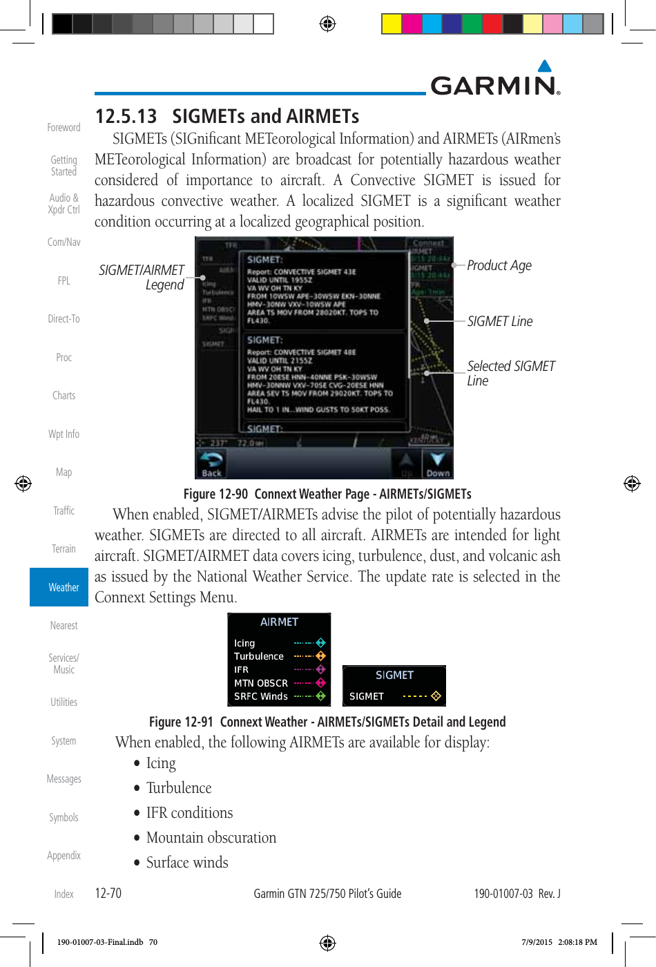
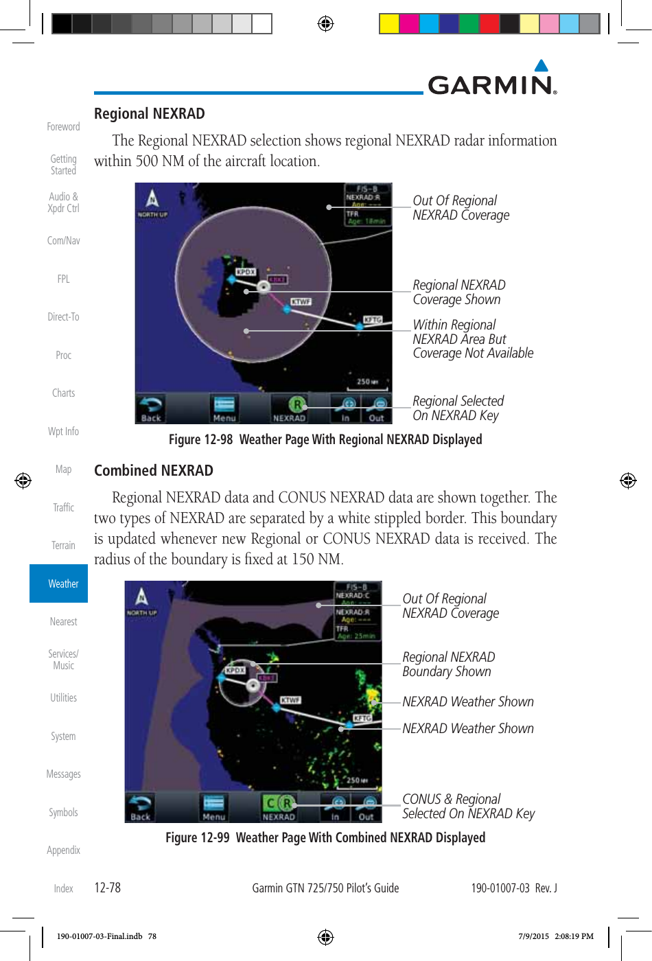
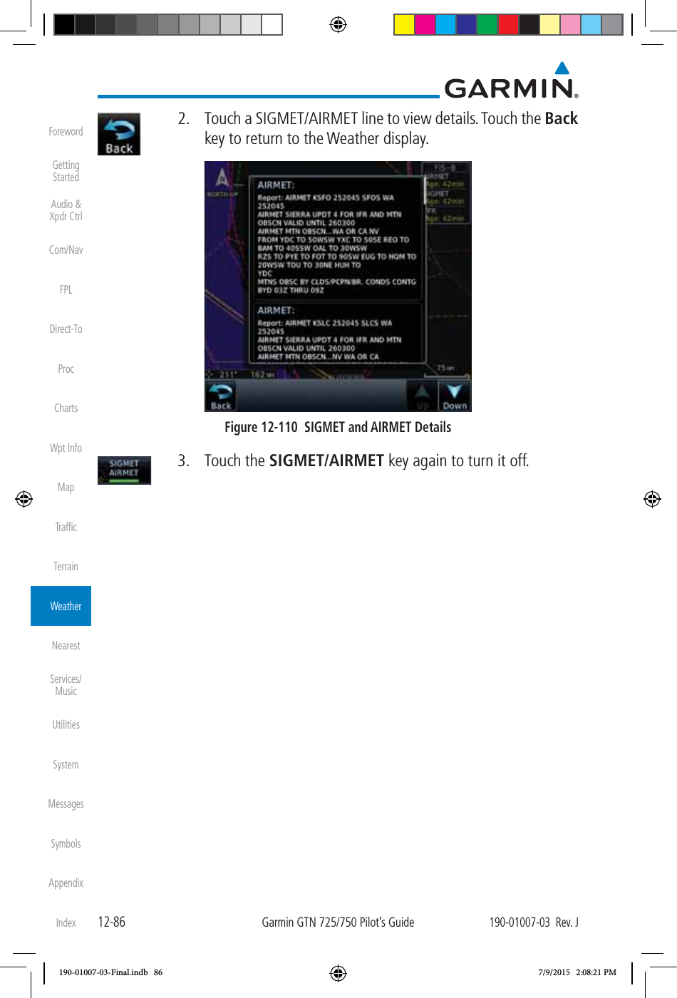
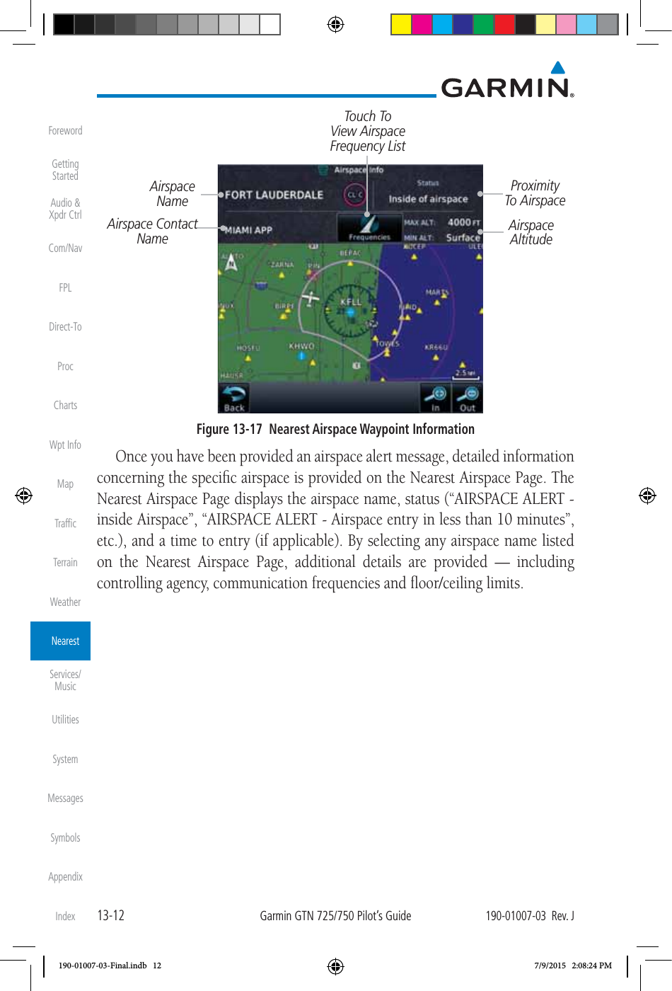
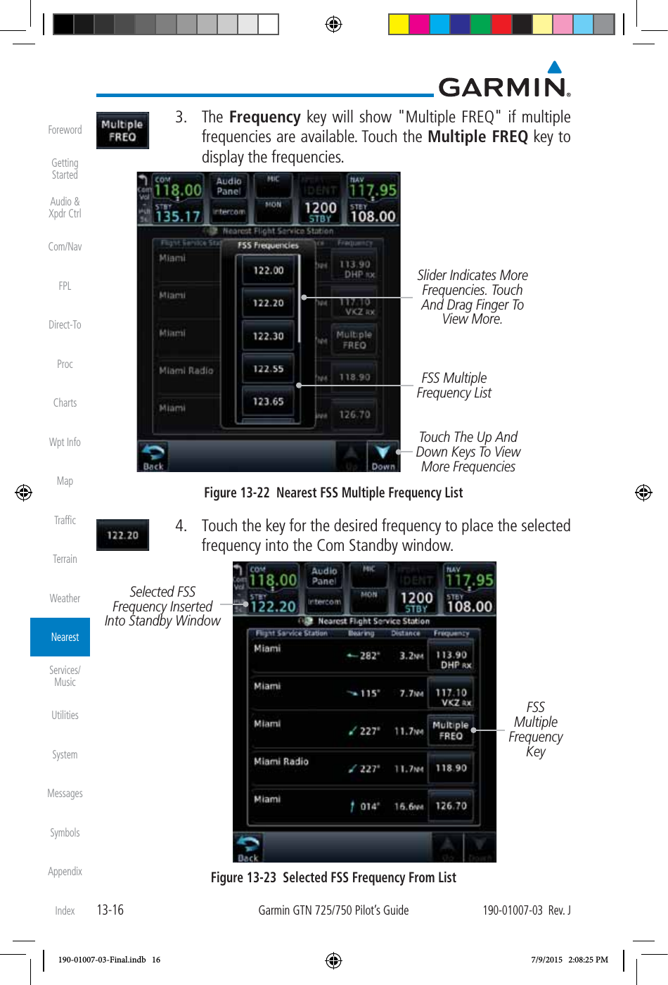
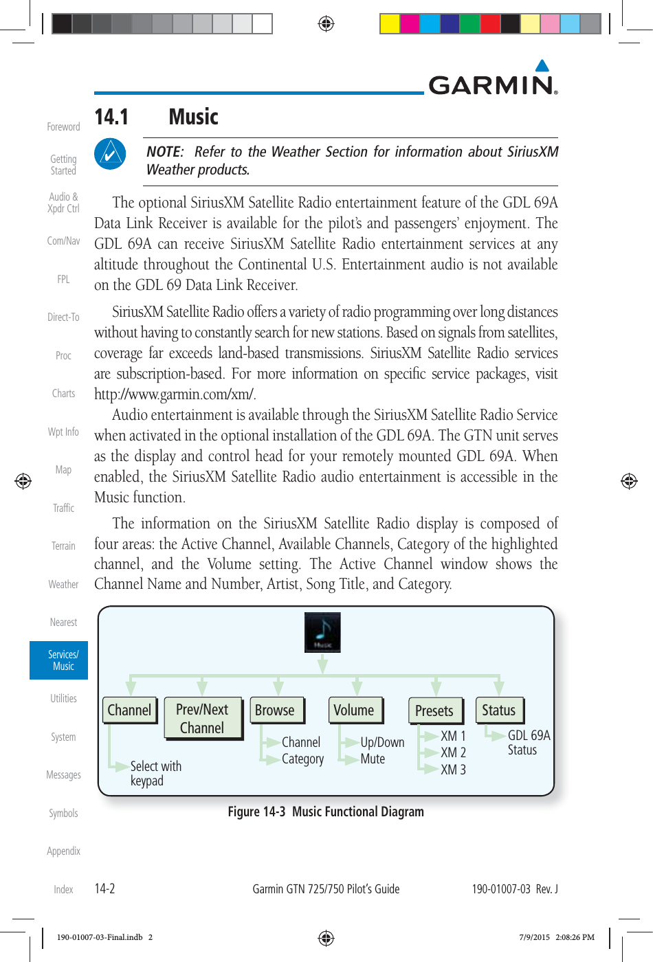
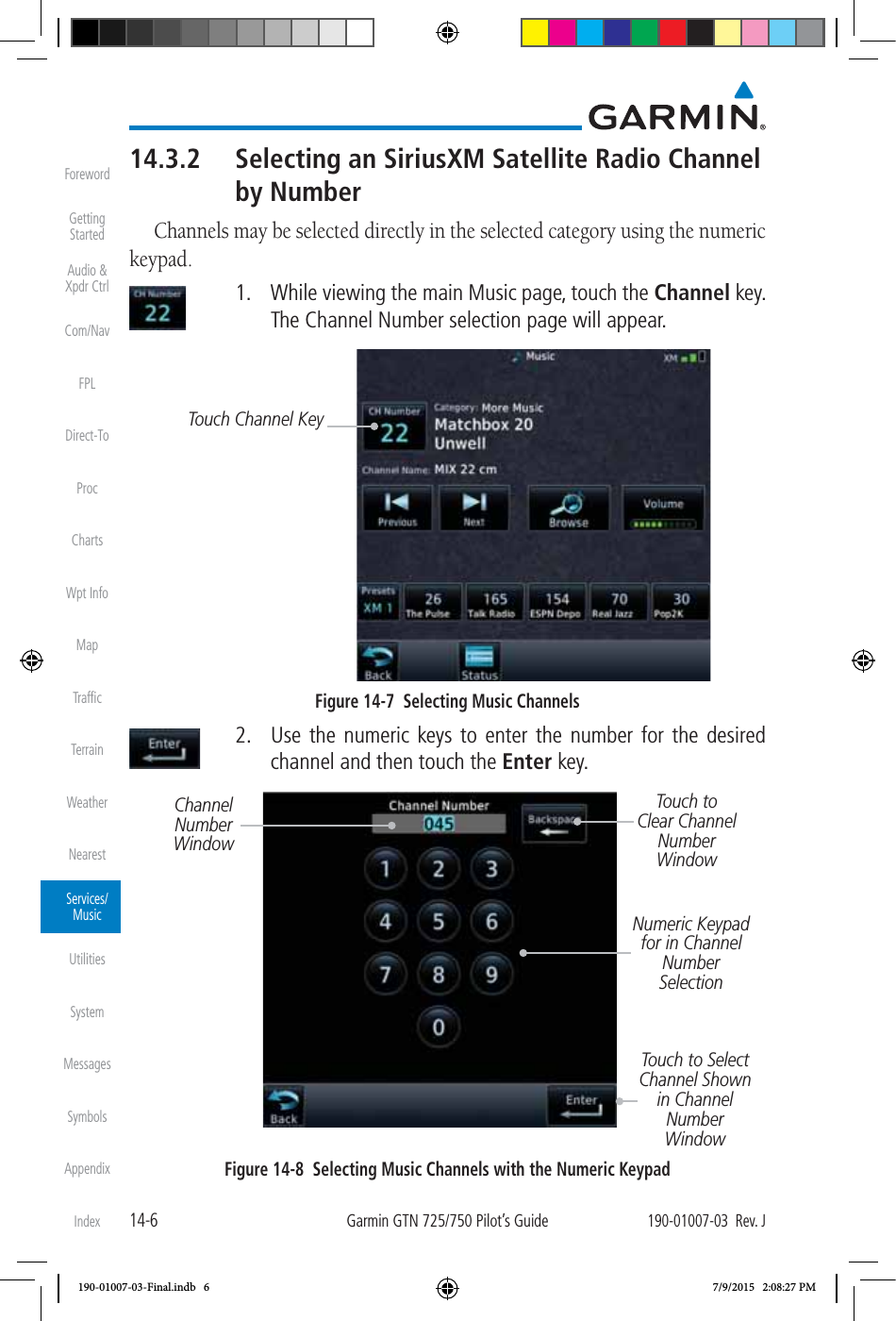
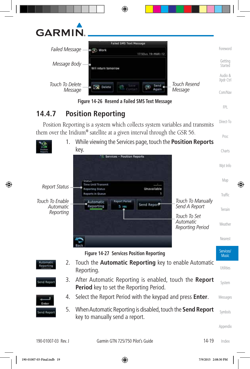
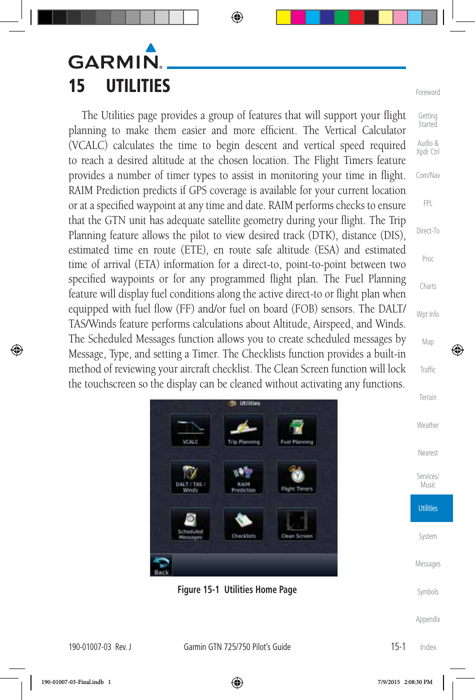
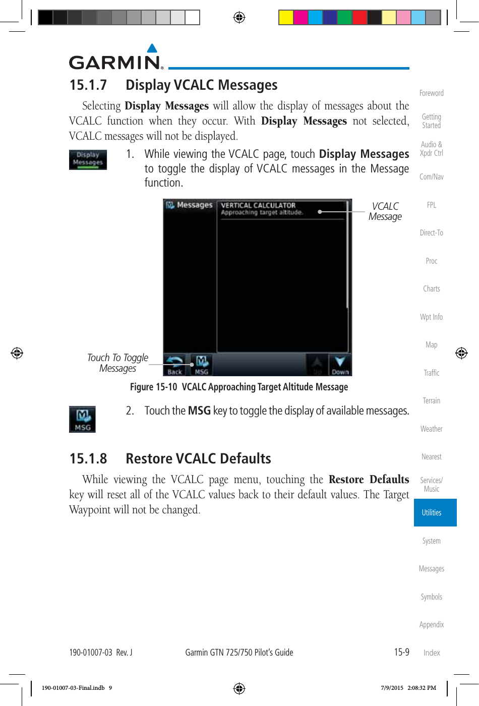
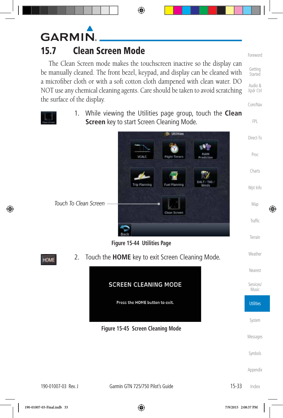
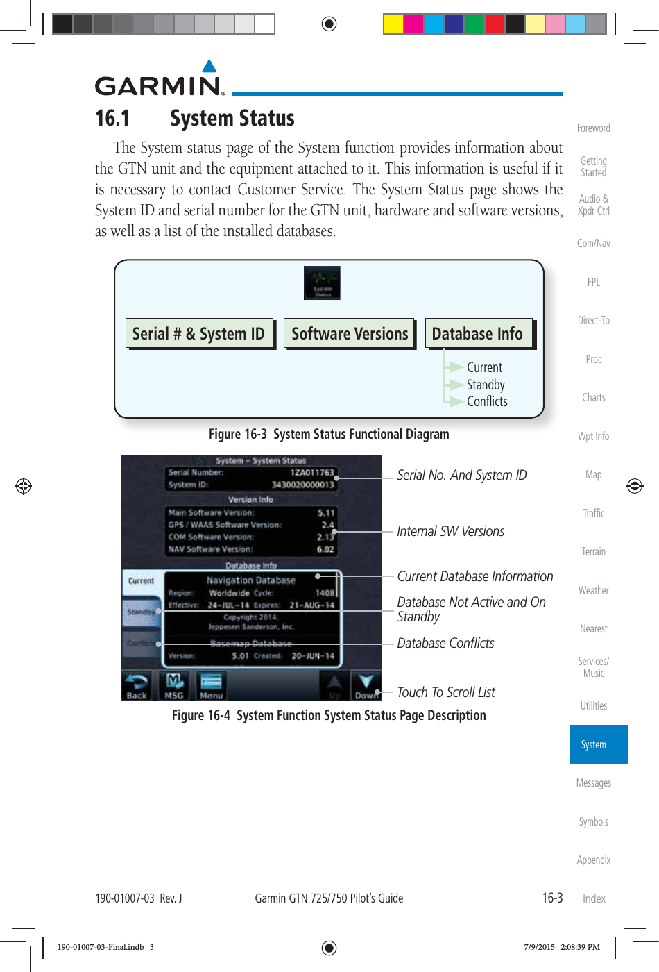
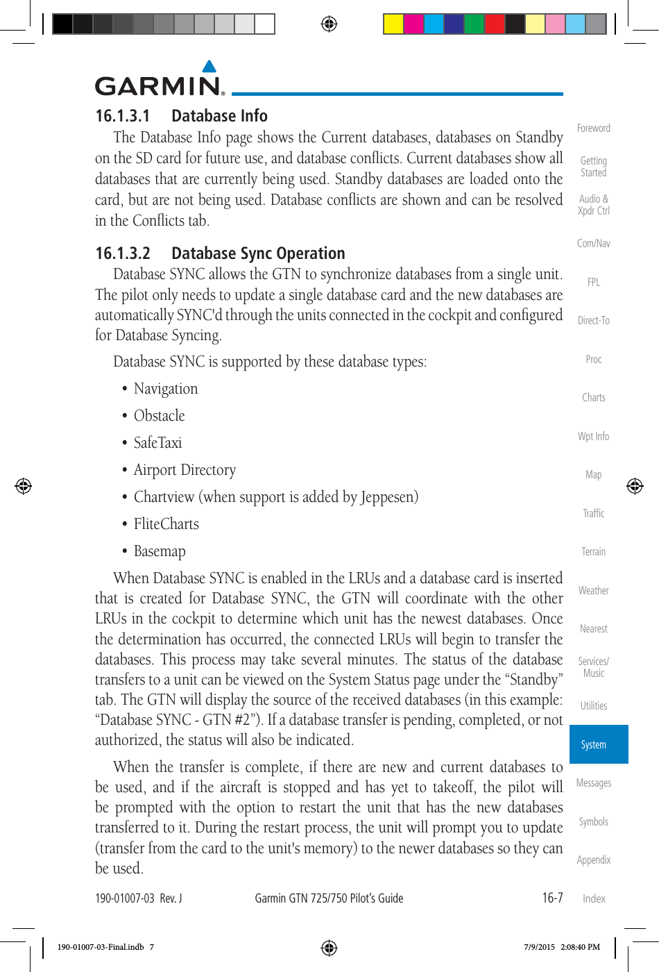
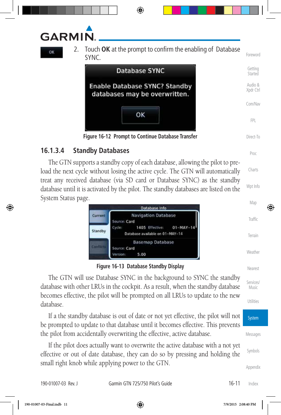
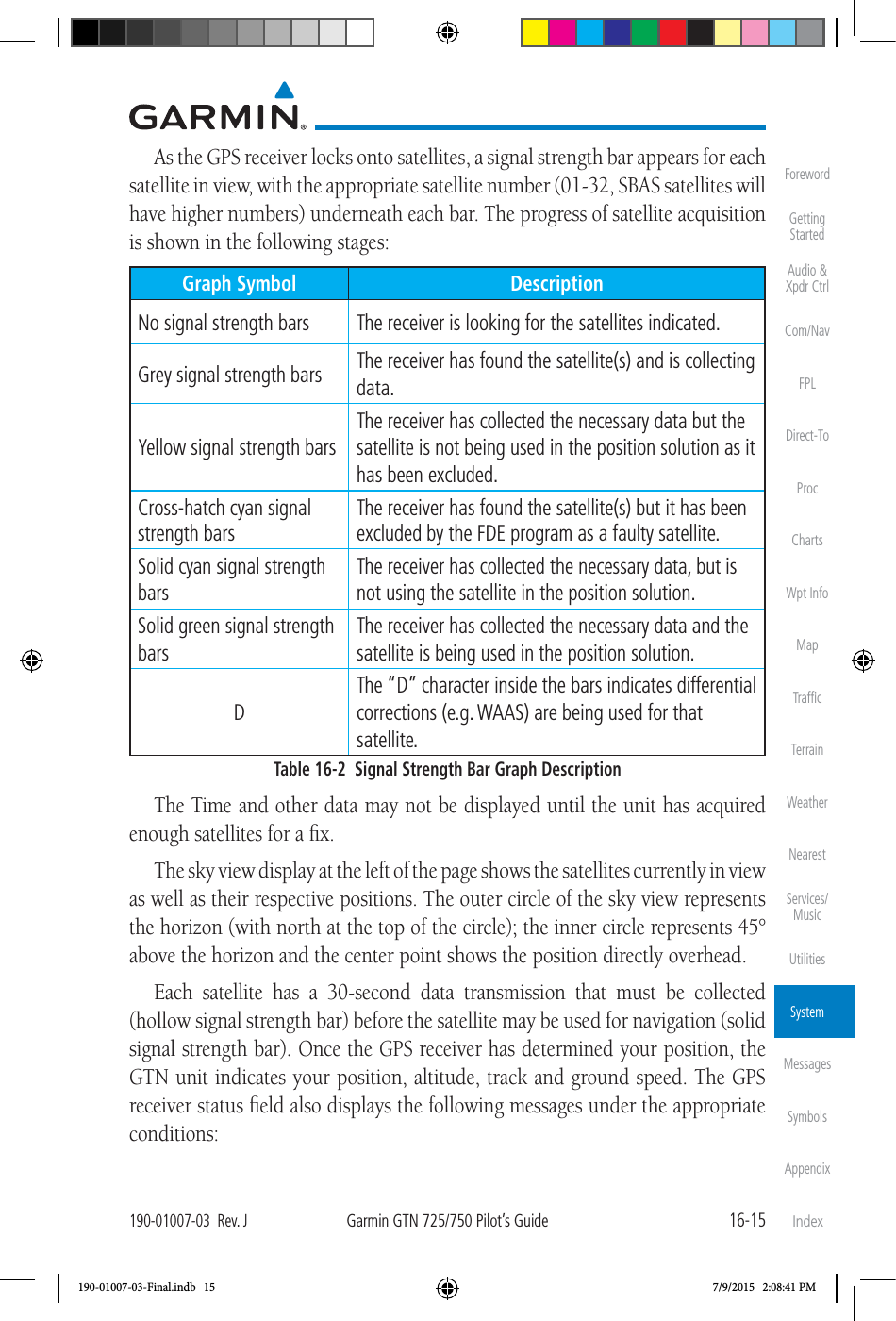
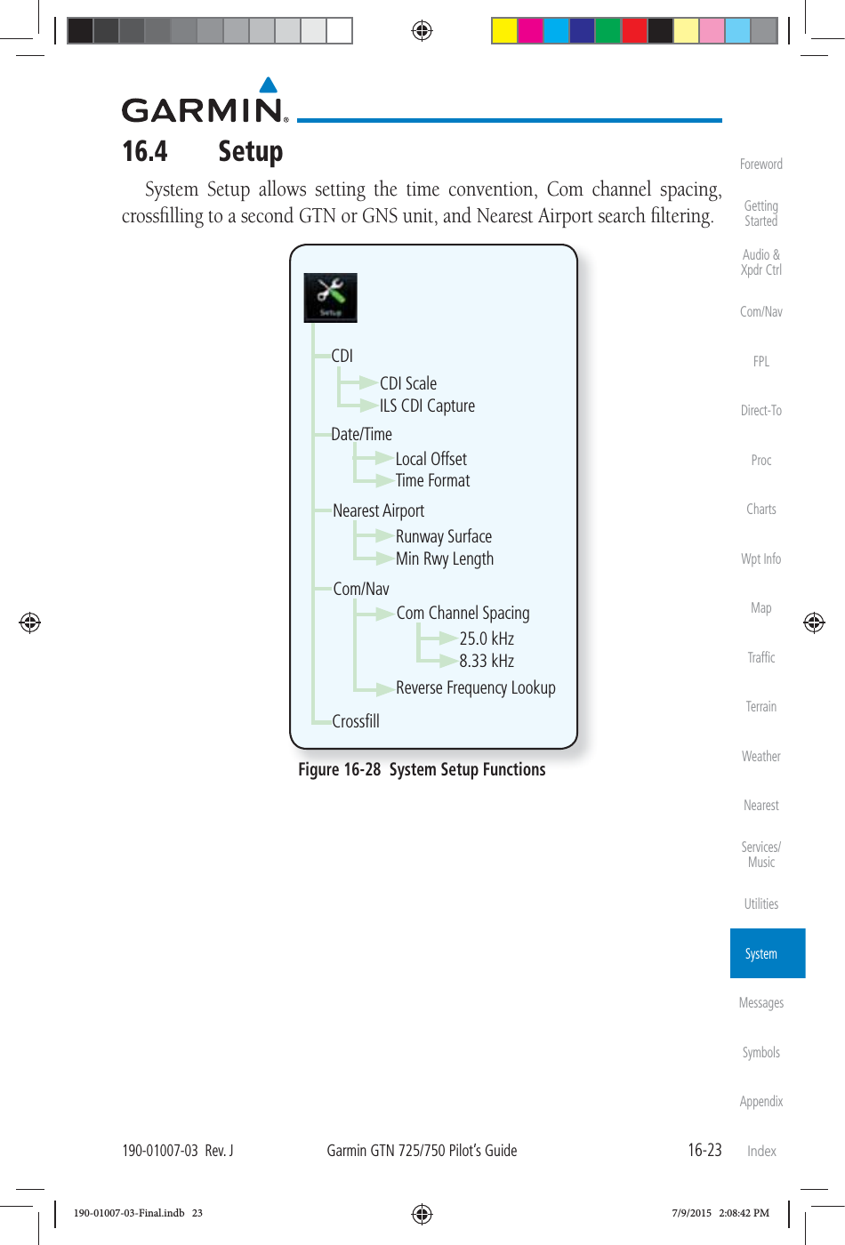
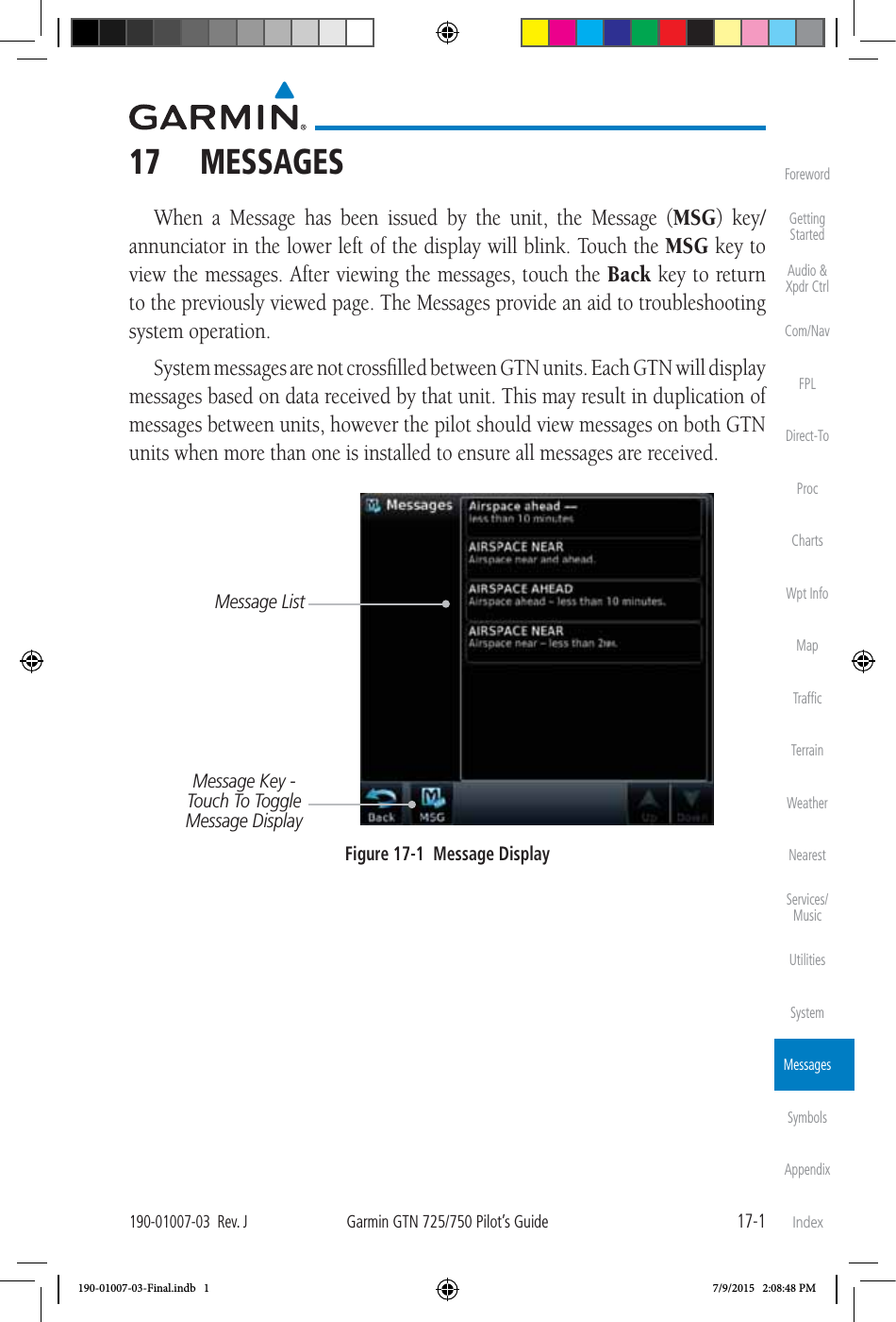
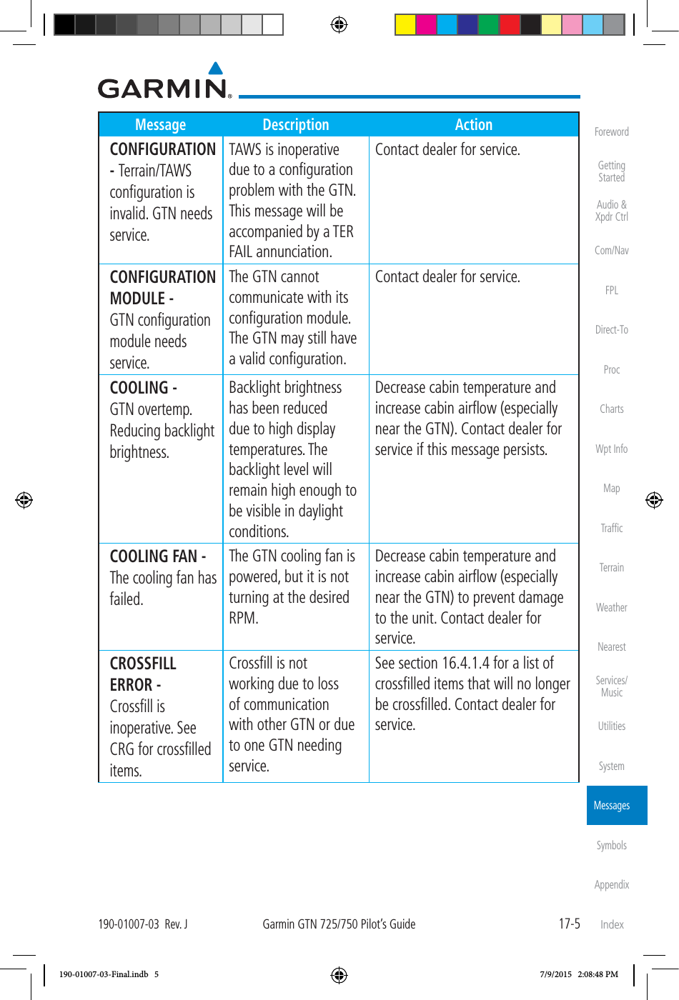
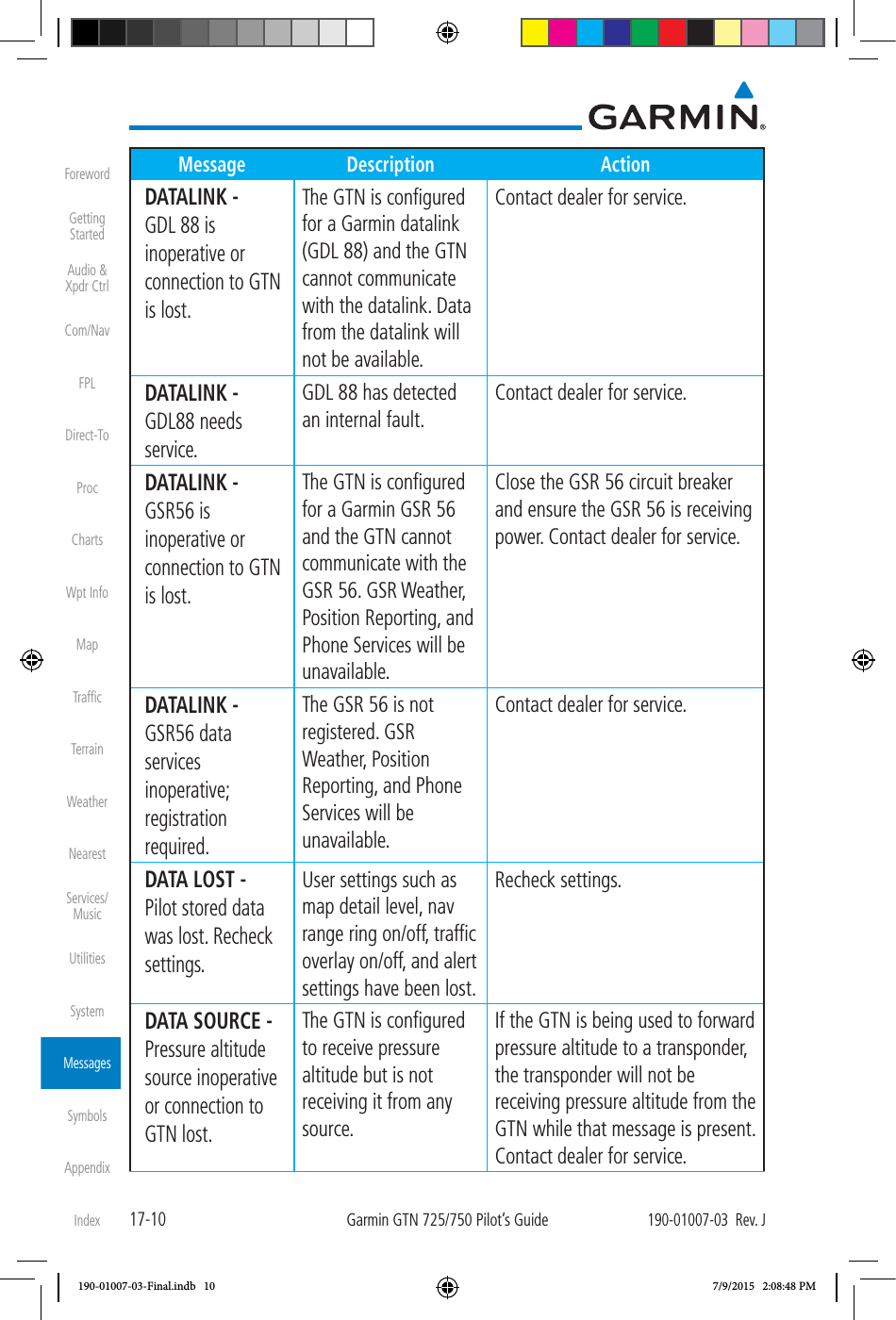
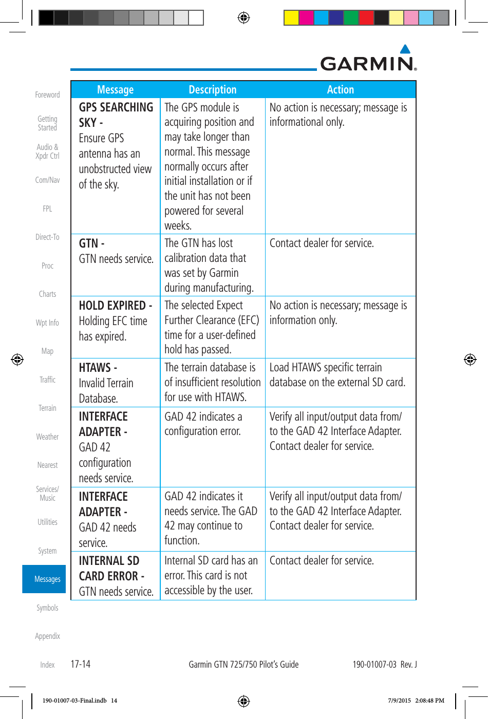
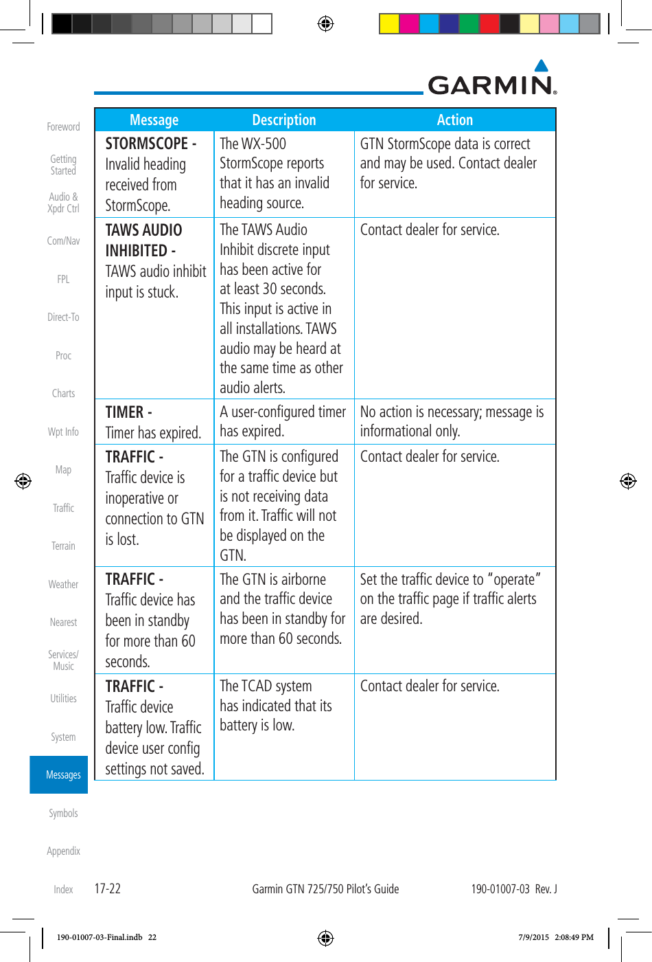
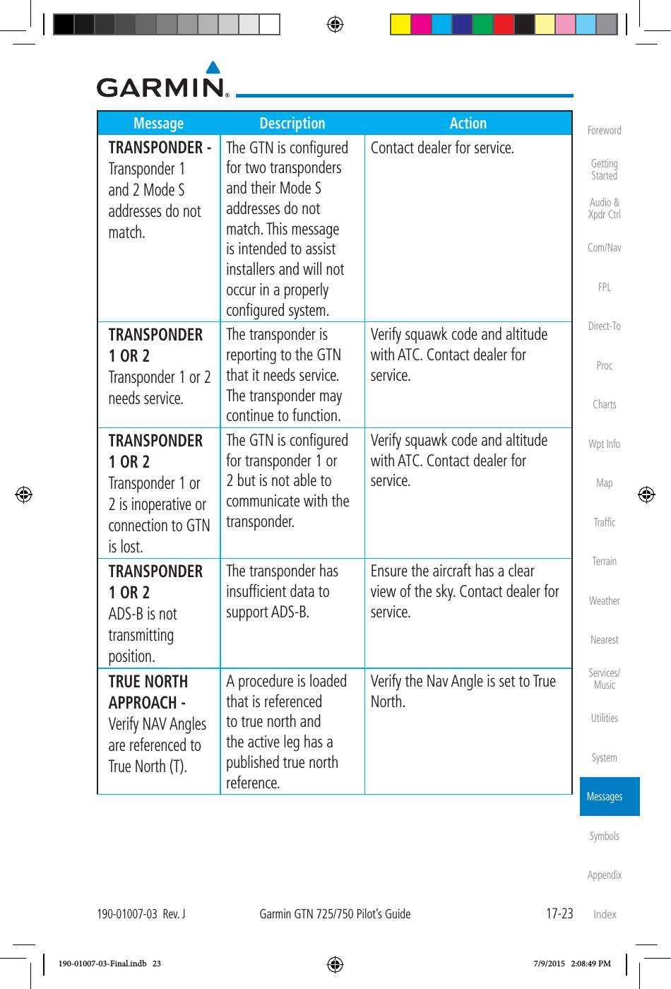
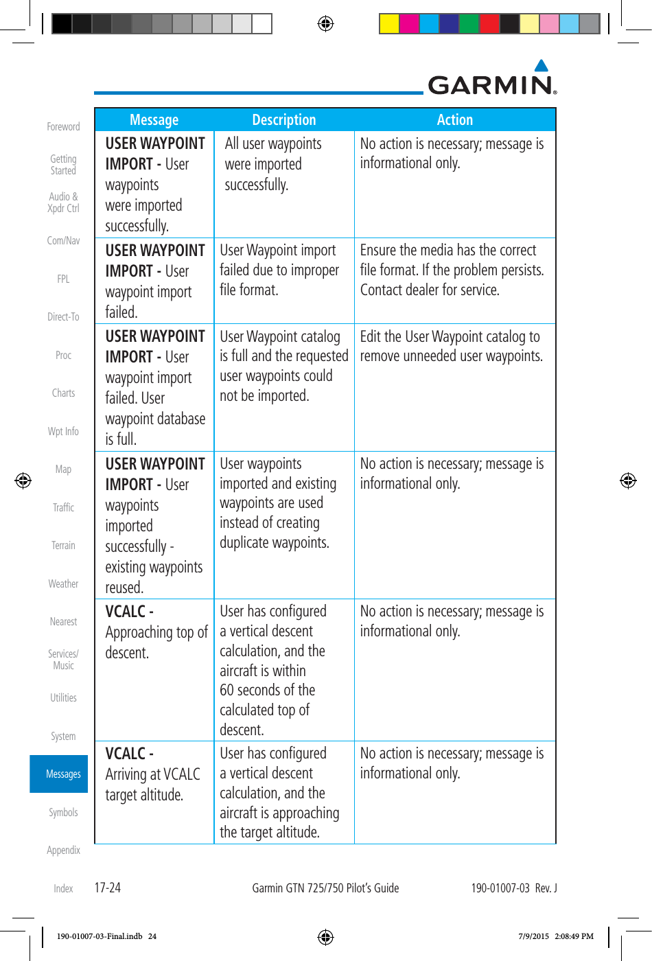
![17-21190-01007-03 Rev. JGarmin GTN 725/750 Pilot’s GuideForewordGetting StartedAudio & Xpdr CtrlCom/NavFPLDirect-ToProcChartsWpt InfoMapTrafficTerrainWeatherNearestServices/MusicUtilitiesSystemMessagesSymbolsAppendixIndexMessage Description ActionREMOTE KEY STUCK - Pilot/Co-Pilot voice command push-to-command key is stuck. The remote push-to-command key/switch has been in pressed position for at least 30 seconds. This input will now be ignored. This input is not available in all installations. Verify the push-to-command key/switch is not stuck. Contact dealer for service if this message persists. SELECT FREQUENCY - Select appropriate NAV frequency for approach. Correct NAV frequency is not set in the active NAV frequency for the approach procedure. Insert the correct frequency into the active navigation frequency window. SET COURSE - Set course on CDI/HSI to [current DTK]. The selected course on the CDI/HSI does not match the current desired track. Set the CDI/HSI selected course to the current desired track. STEEP TURN - Aircraft may overshoot course during turn. Flight plan contains an acute course change ahead which will require a bank in excess of normal to follow the guidance. If coupled to the autopilot, the autopilot may not be able to execute the steep turn needed to follow the course guidance. No action is necessary; message is informational only. If desired, slow the aircraft to shallow the turn. STORMSCOPE - StormScope is inoperative or connection to GTN is lost. The GTN is configured for a WX-500 StormScope but is not receiving data from it. Close the Stormscope circuit breaker and ensure Stormscope is receiving power. Contact dealer for service. 190-01007-03-Final.indb 21 7/9/2015 2:08:49 PM](https://usermanual.wiki/Garmin/0163700.User-Manual-3/User-Guide-2814670-Page-172.png)
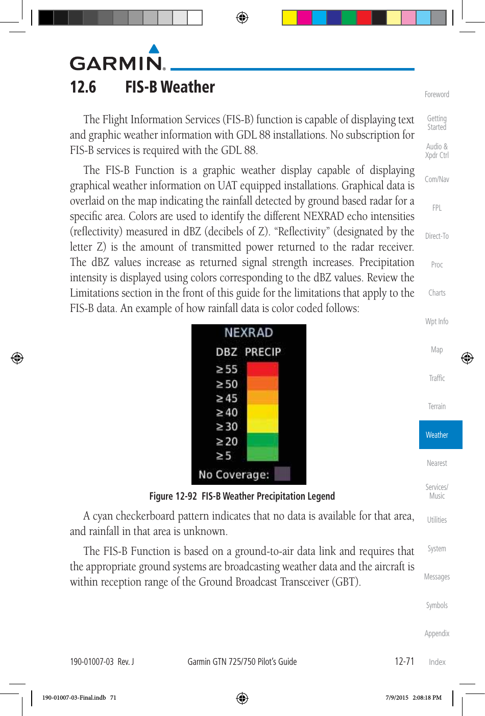
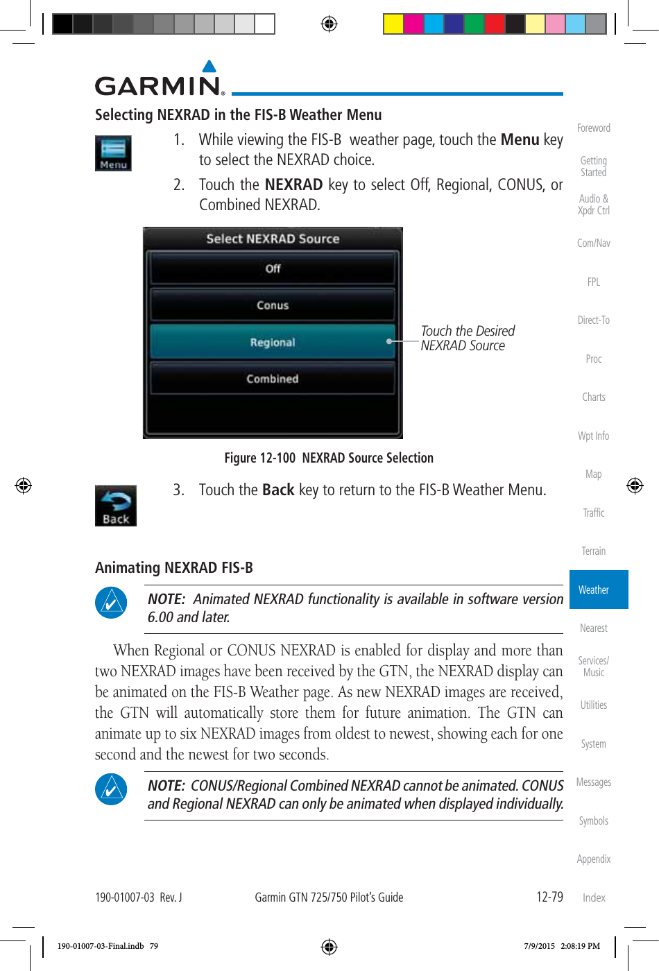
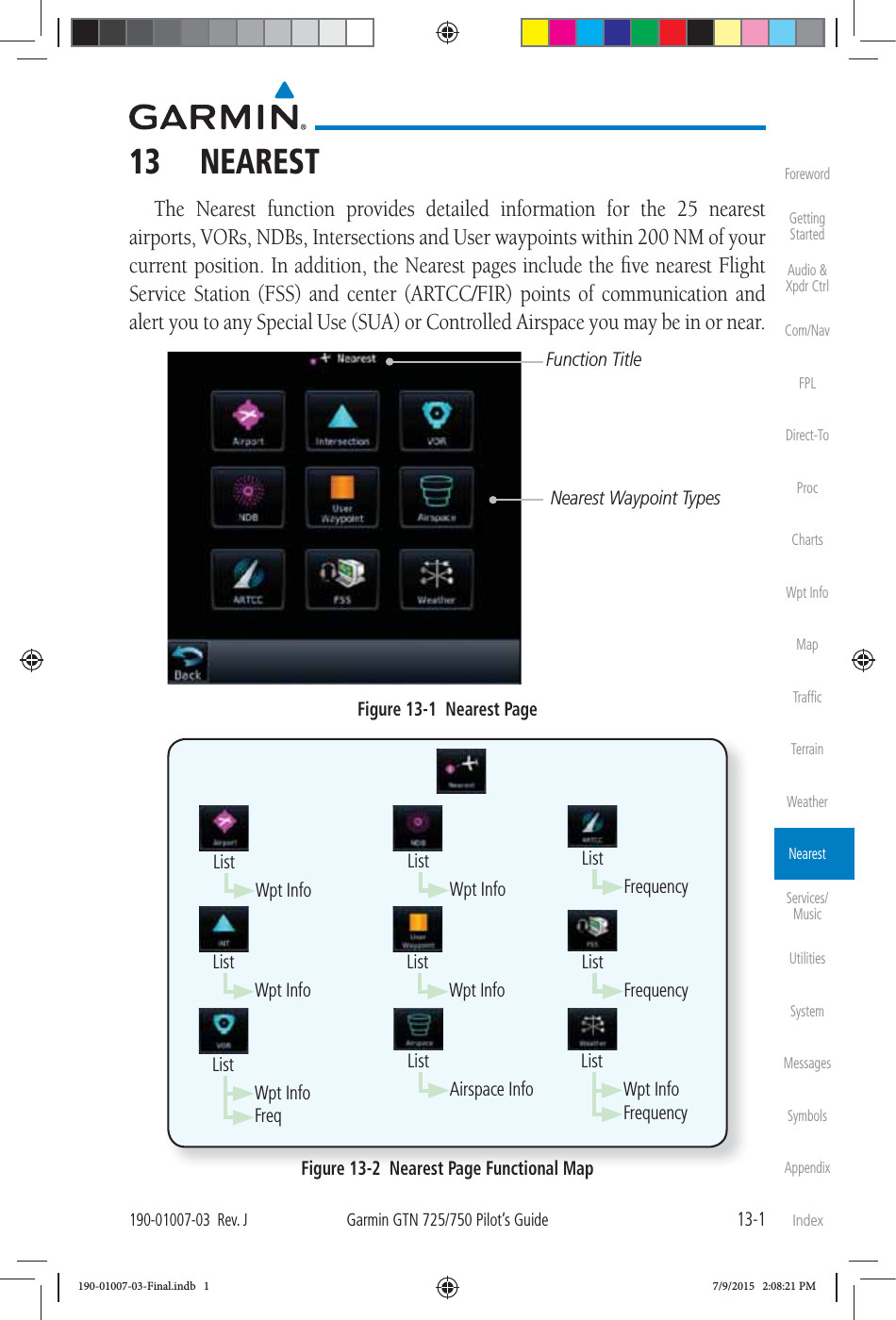
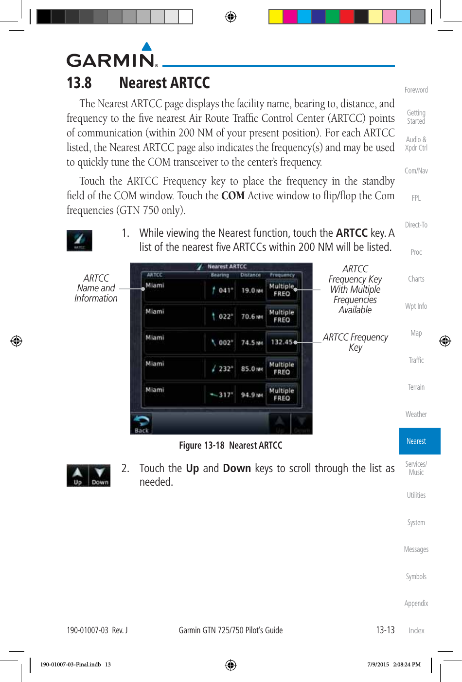
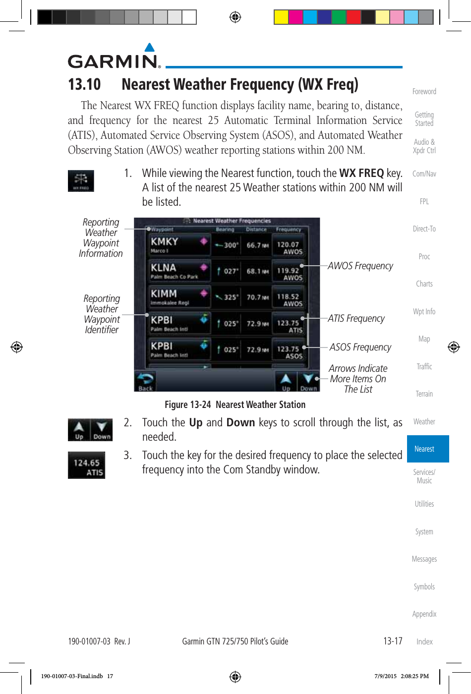
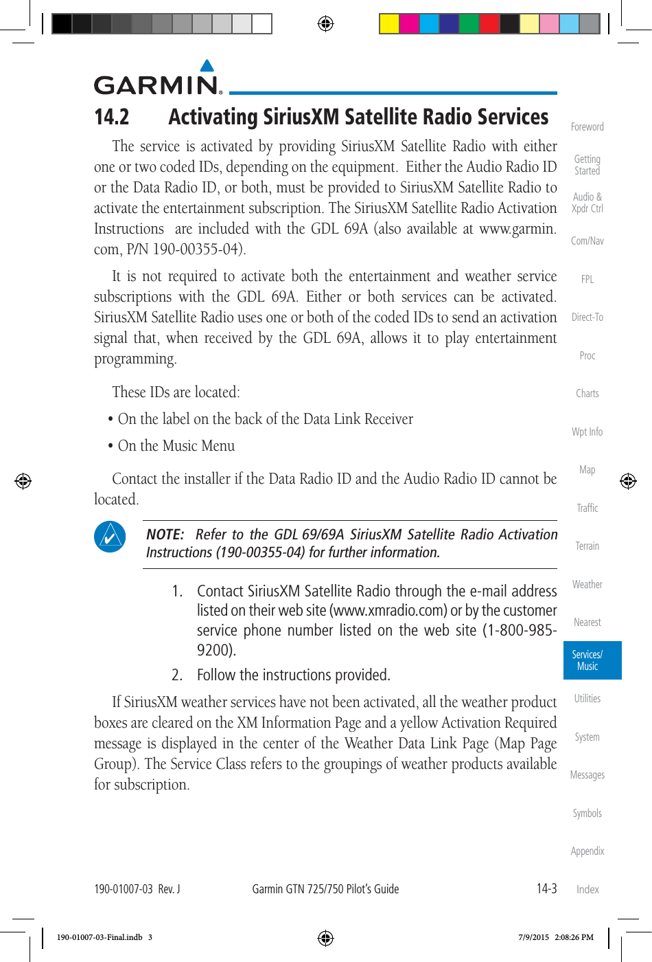
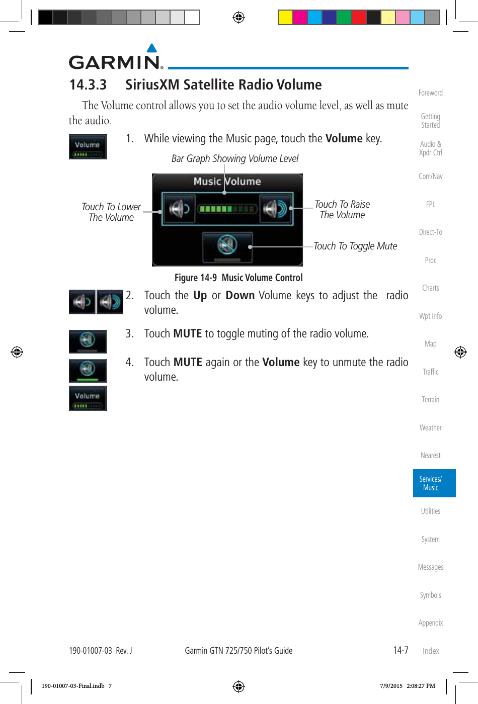
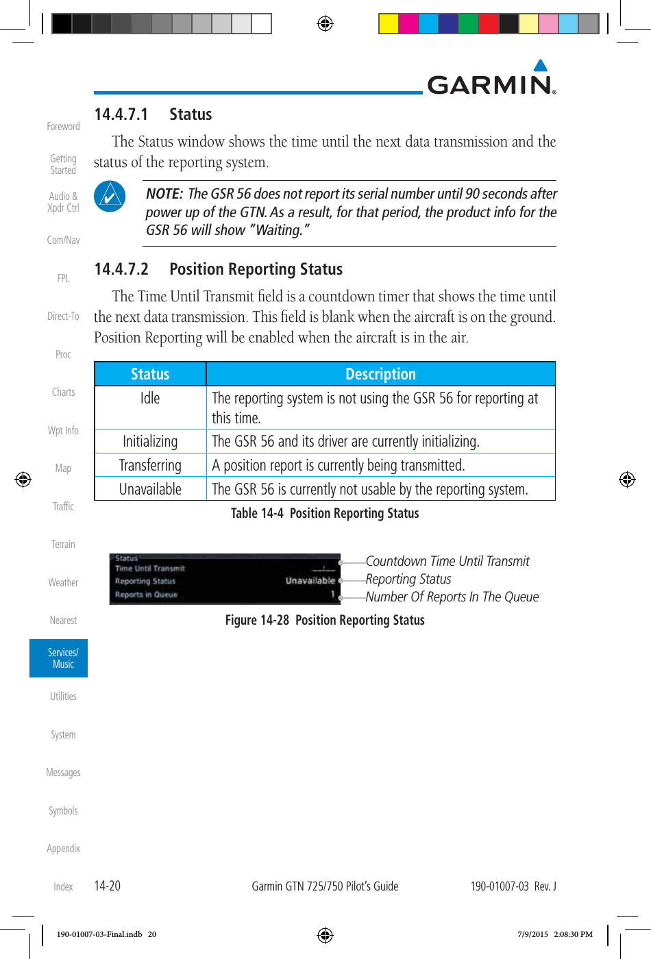
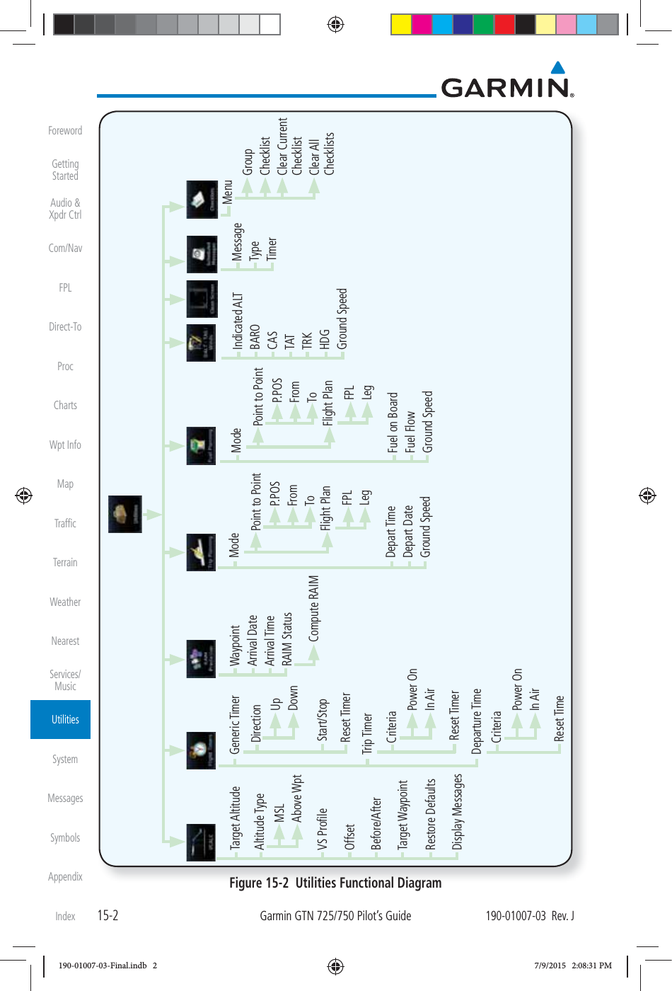
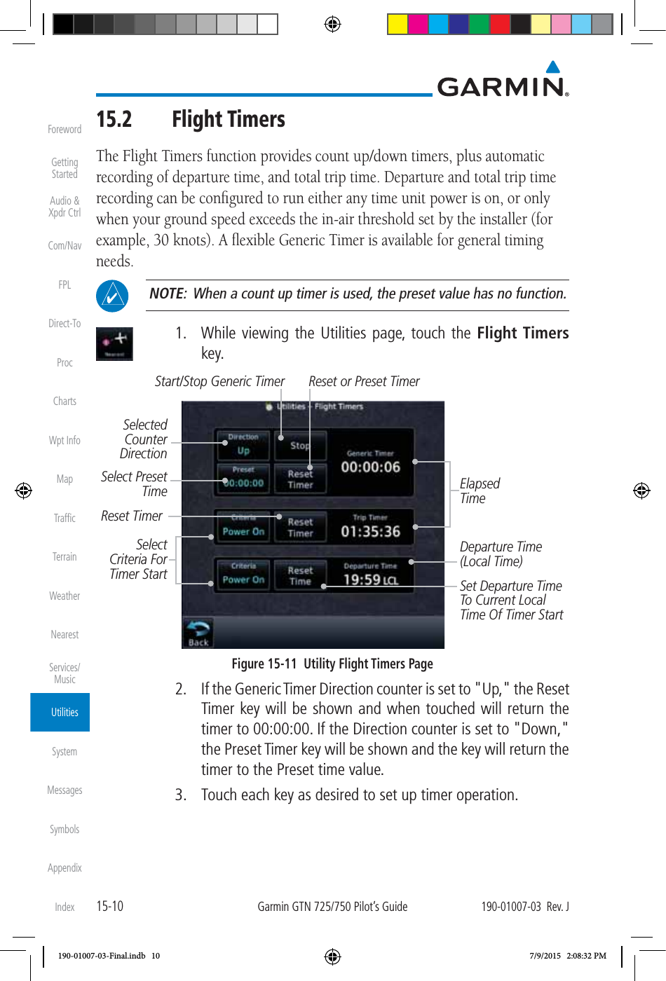
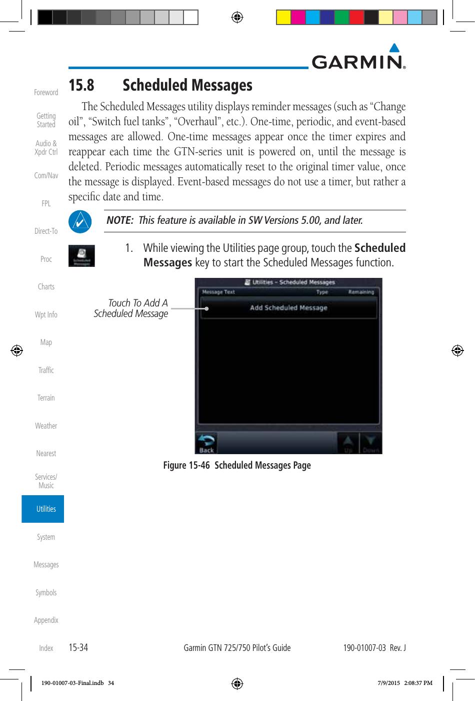
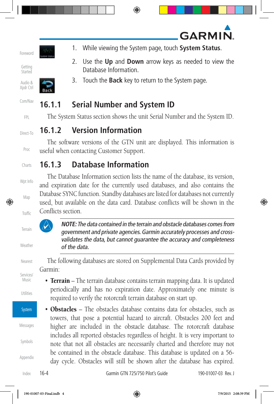
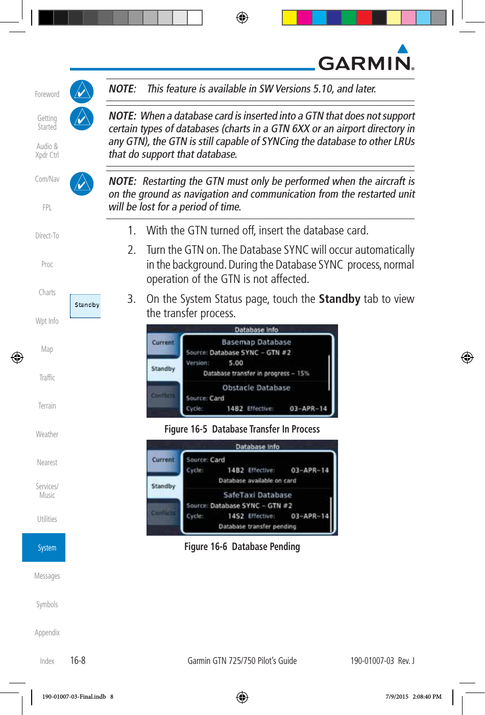
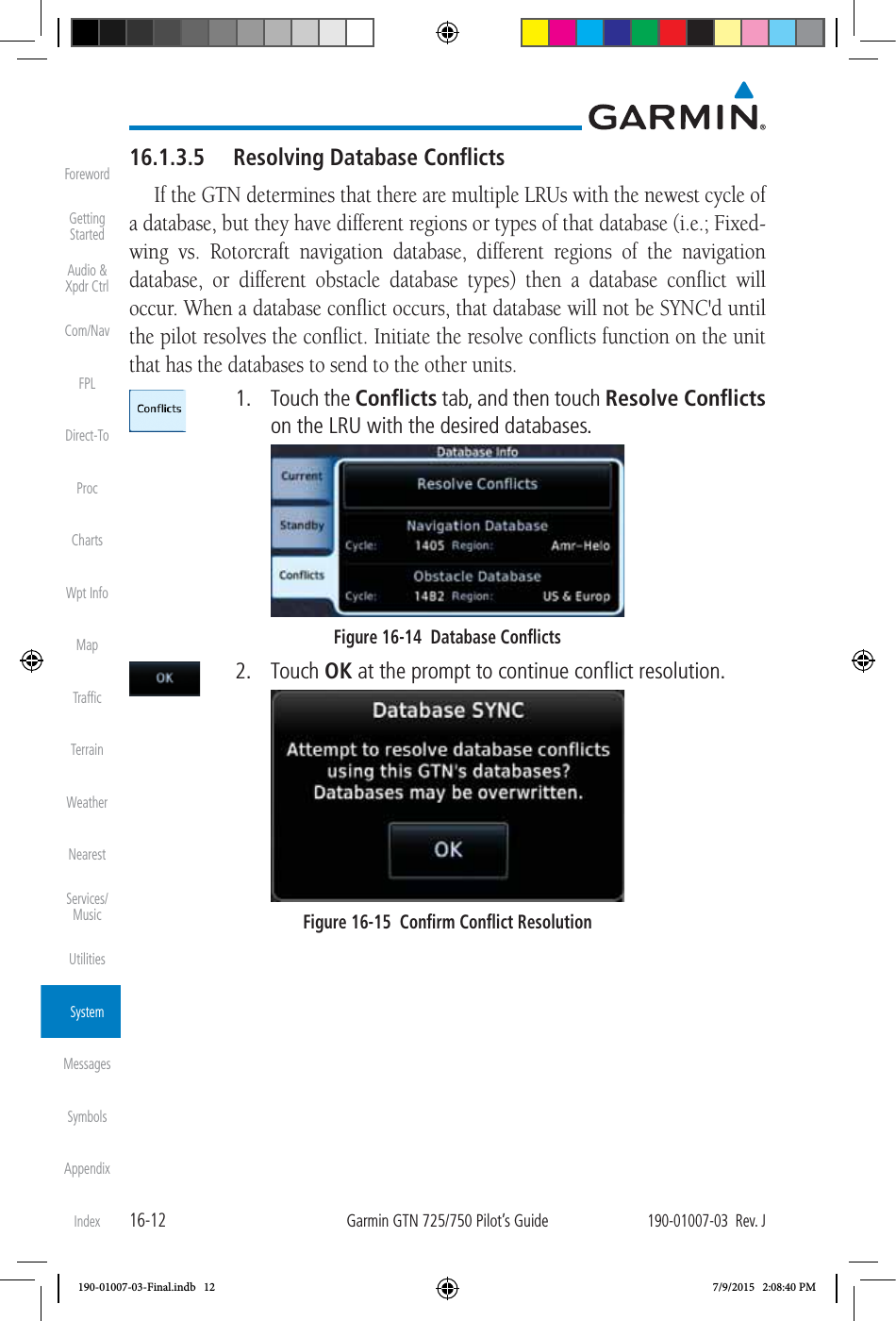
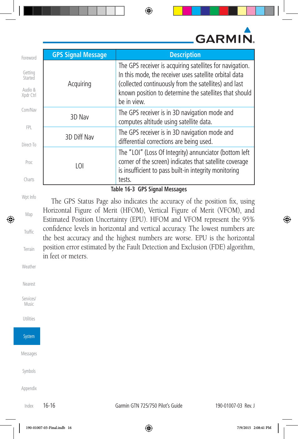
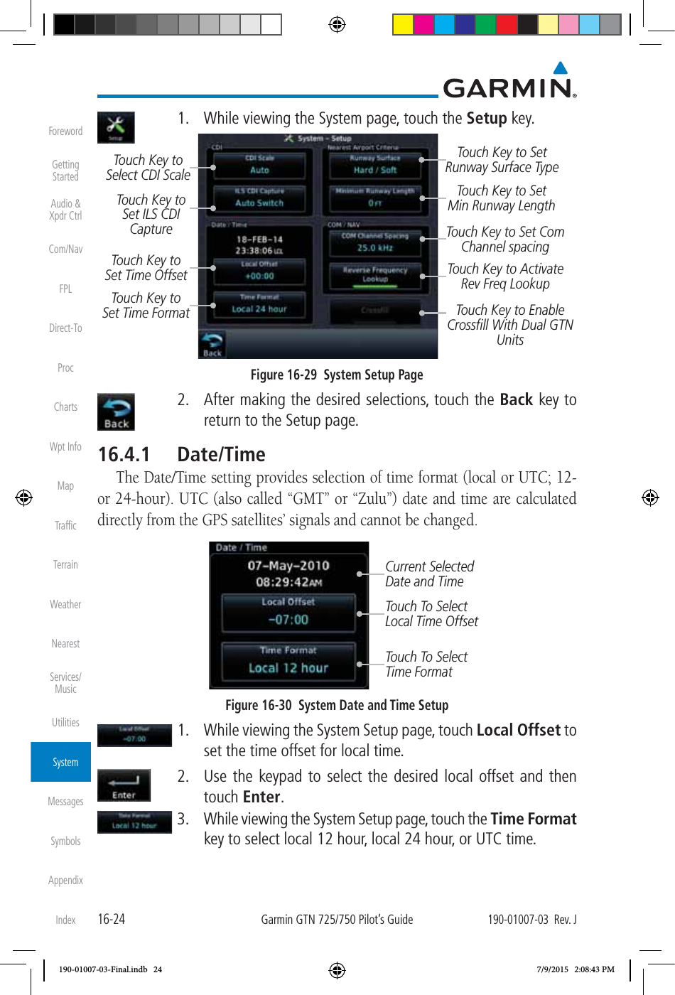
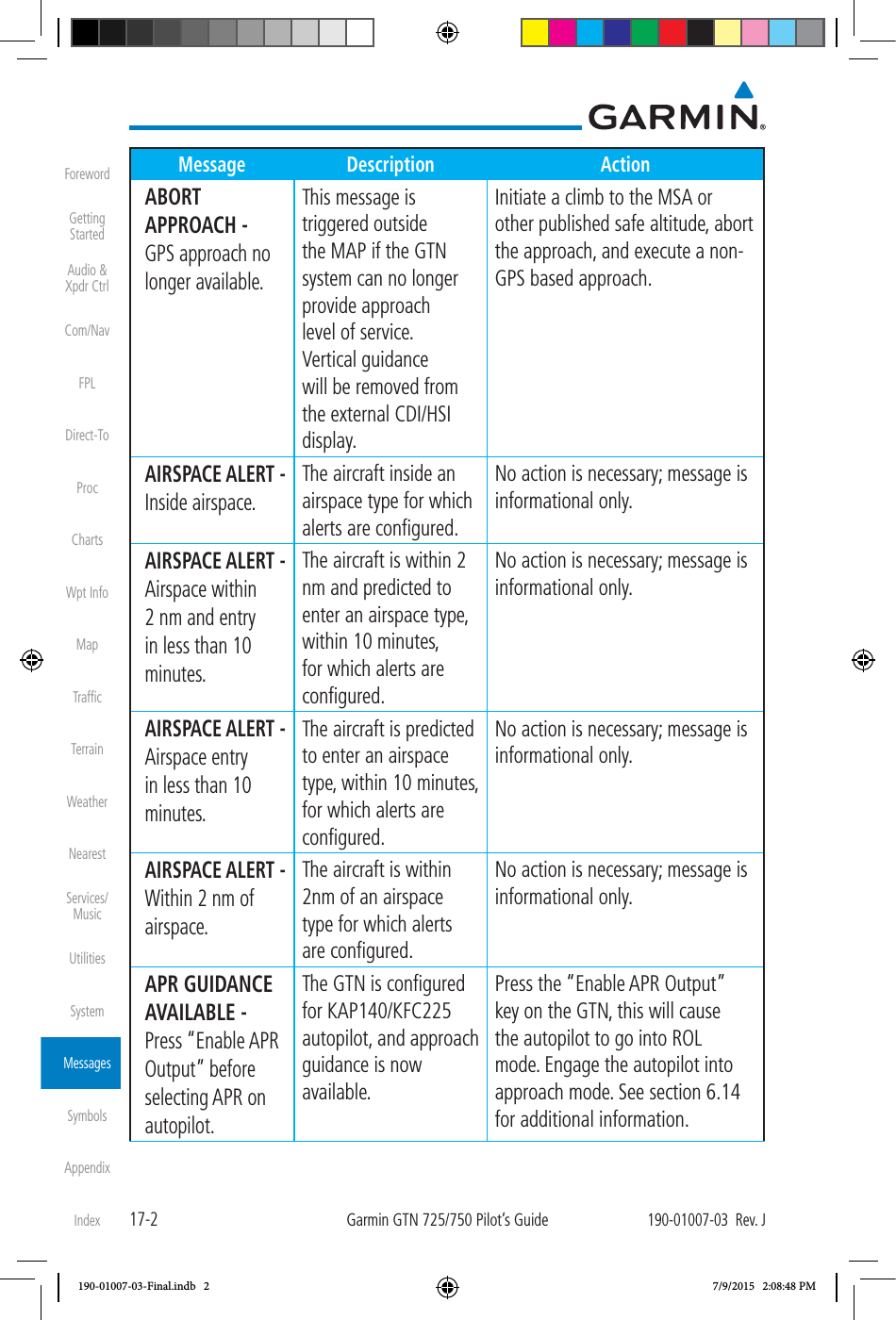
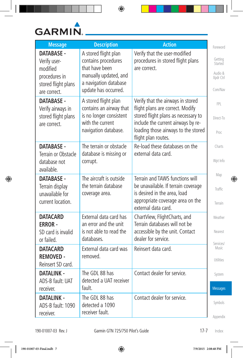
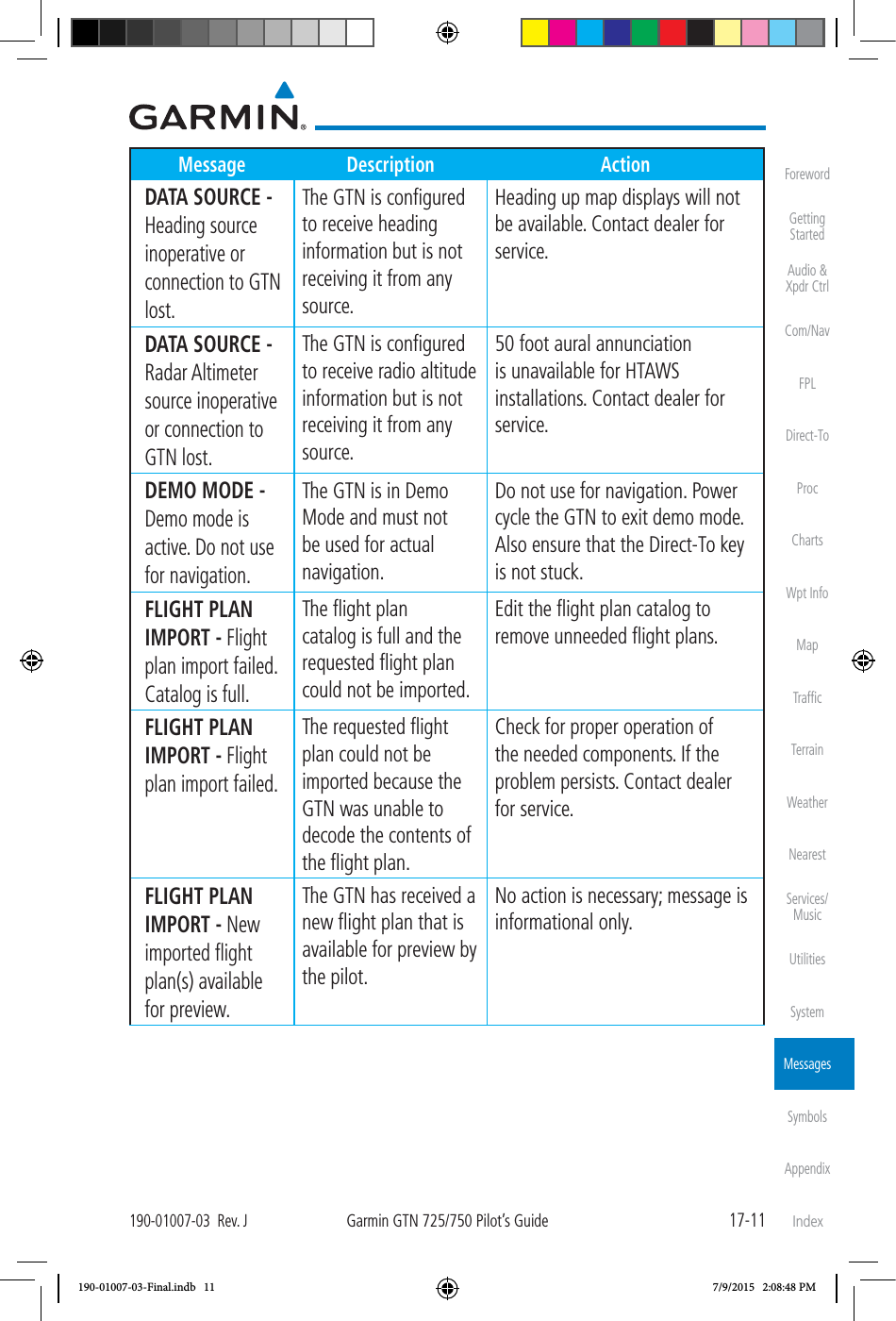
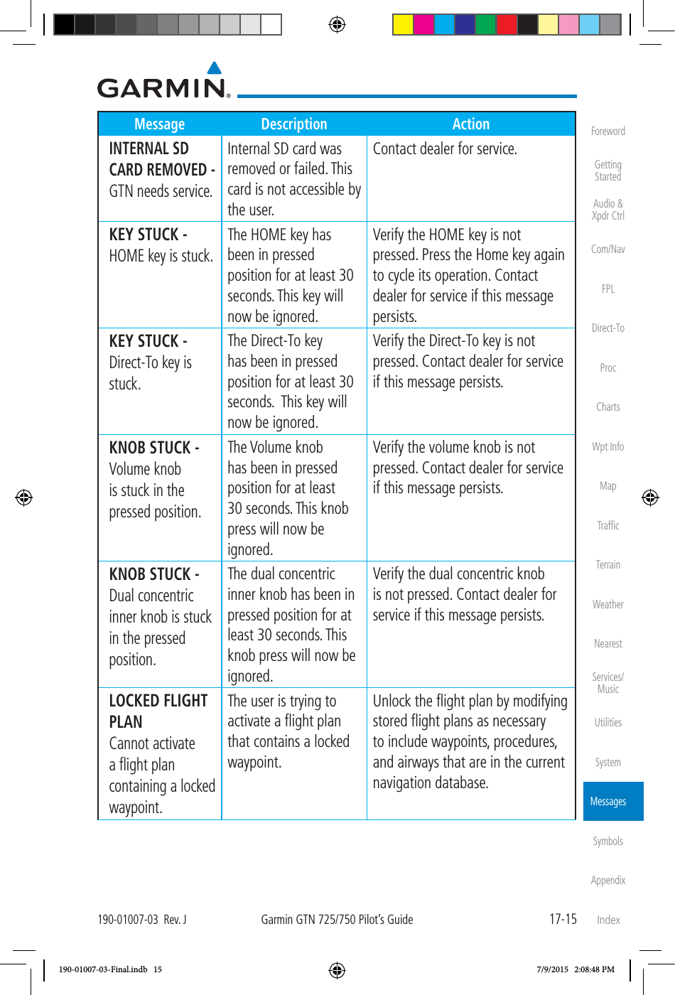
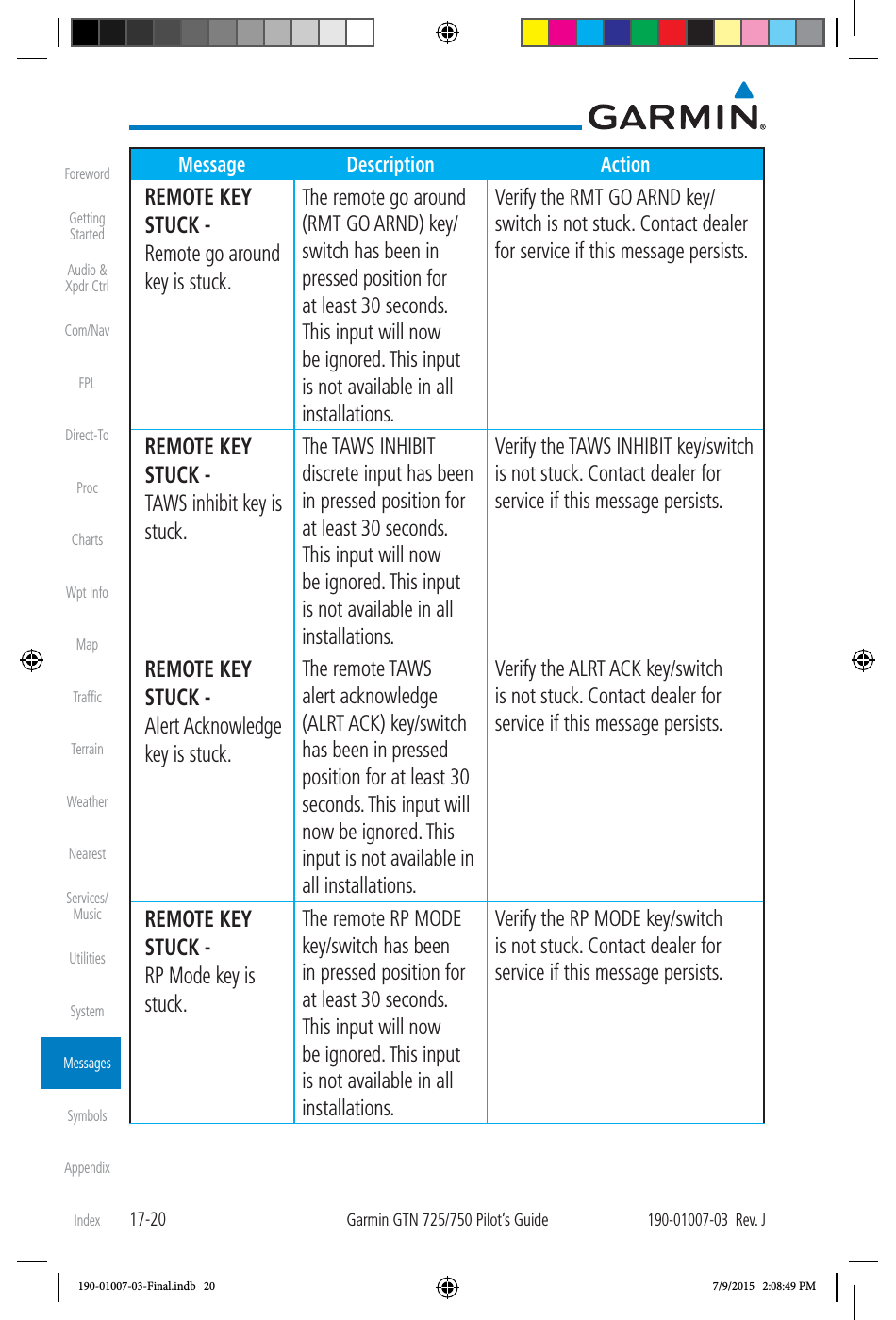
![17-25190-01007-03 Rev. JGarmin GTN 725/750 Pilot’s GuideForewordGetting StartedAudio & Xpdr CtrlCom/NavFPLDirect-ToProcChartsWpt InfoMapTrafficTerrainWeatherNearestServices/MusicUtilitiesSystemMessagesSymbolsAppendixIndexMessage Description ActionVLOC RECEIVER - Navigation receiver needs service. The nav radio is reporting that it needs service. The nav radio may continue to function. Use GPS based navigation. Contact dealer for service. VLOC RECEIVER - Navigation receiver has failed. The nav radio is not communicating property with the system. Use GPS based navigation. Contact dealer for service. WAYPOINT - Arriving at [wpt name]. User has configured the arrival alarm and is within the specified distance. No action is necessary; message is informational only. WX ALERT - Possible severe weather ahead. The weather radar system is indicating the presence of severe weather ahead. Check weather radar. See Section12.4.8.2 for more information. WX RADAR FAIL - Weather radar is inoperative. The GTN is configured for a weather radar but is not receiving data from it. Weather Radar will not be displayed on the GTN. Contact dealer for service. WX RADAR SERVICE - Weather radar needs service. Return unit for repair. Weather radar is reporting a system fault. Contact dealer for service. Table 17-1 Messages190-01007-03-Final.indb 25 7/9/2015 2:08:49 PM](https://usermanual.wiki/Garmin/0163700.User-Manual-3/User-Guide-2814670-Page-176.png)
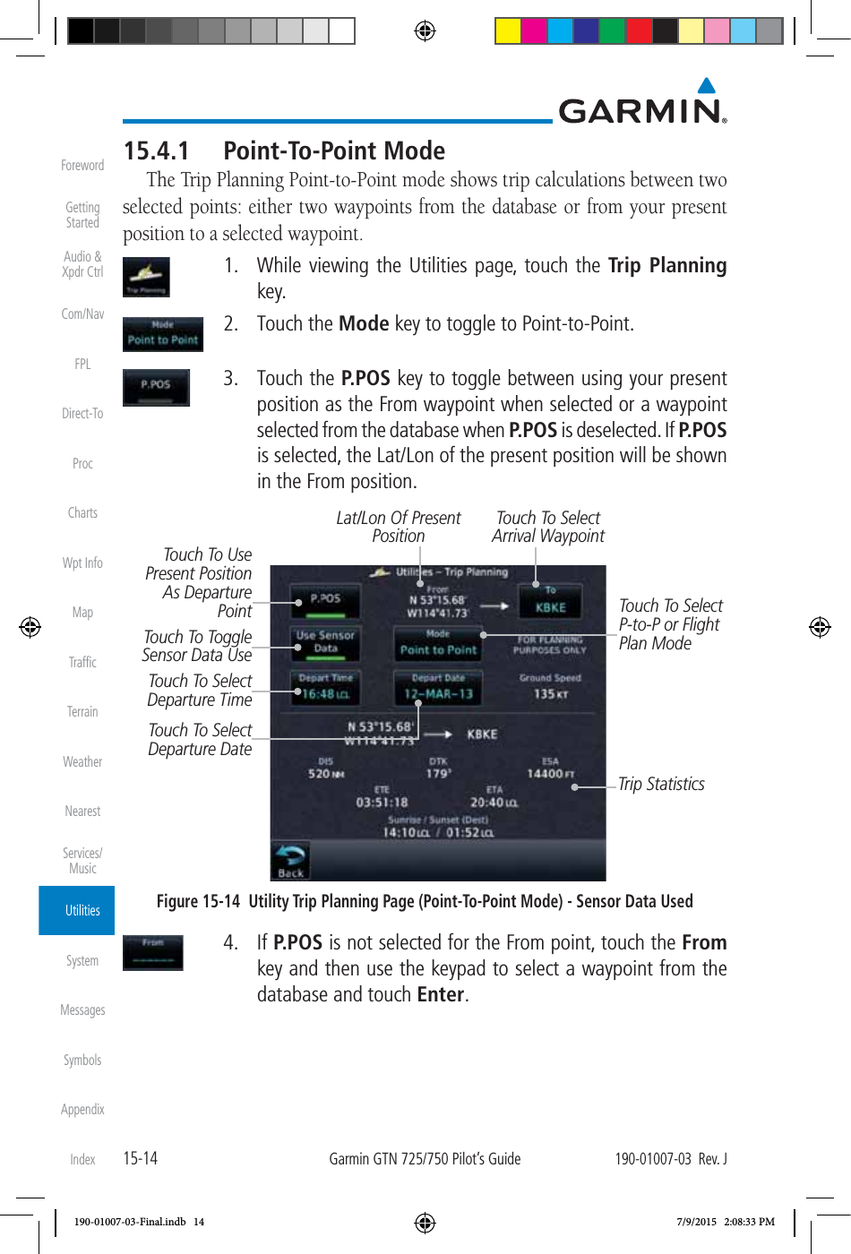
![19-15190-01007-03 Rev. JGarmin GTN 725/750 Pilot’s GuideForewordGetting StartedAudio & Xpdr CtrlCom/NavFPLDirect-ToProcChartsWpt InfoMapTrafficTerrainWeatherNearestServices/MusicUtilitiesSystemMessagesSymbolsAppendixIndex 3. Touch the Demo key in the lower part of the display to reach the Demo Setup functions. Touch For GPS SettingsTouch For NAV SettingsTouch For Date And Time SettingsFigure 19-3 Demo Mode Setup 4. Touch the GPS key to reach the Demo GPS Settings page. The Position Error values (Horizontal Protection Level Fault Detection [HPL FD], HPL SBAS, and Vertical Protection Level [VPL] SBAS) may be adjusted to reflect errors induced by naturally occurring conditions, but are normally not adjusted for most Demo mode operations. Touch For HPL SBAS SettingsTouch For VPL SBAS SettingsTouch To Select GPS SolutionTouch To Select Lat/Lon Coordinates For Current PositionTouch To Select Current Position From A Wpt In The DatabaseTouch To Select HPL FD Values, If DesiredFigure 19-4 Demo Mode GPS Settings190-01007-03-Final.indb 15 7/9/2015 2:08:55 PM](https://usermanual.wiki/Garmin/0163700.User-Manual-3/User-Guide-2814670-Page-202.png)