Garmin 0194500 AIRBORNE COMMUNICATIONS TRANSCEIVER User Manual
Garmin International Inc AIRBORNE COMMUNICATIONS TRANSCEIVER Users Manual
UserManual.wiki
>
Garmin
>
0194500 User Manual
Users Manual
Navigation menu
Upload a User Manual
Namespaces
Wiki Guide
HTML
PDF
Info
Views
User Manual
Discussion / Help
Navigation


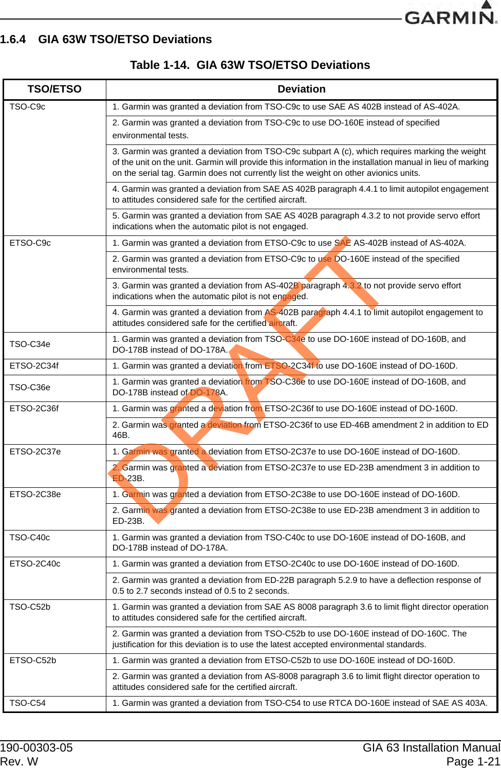

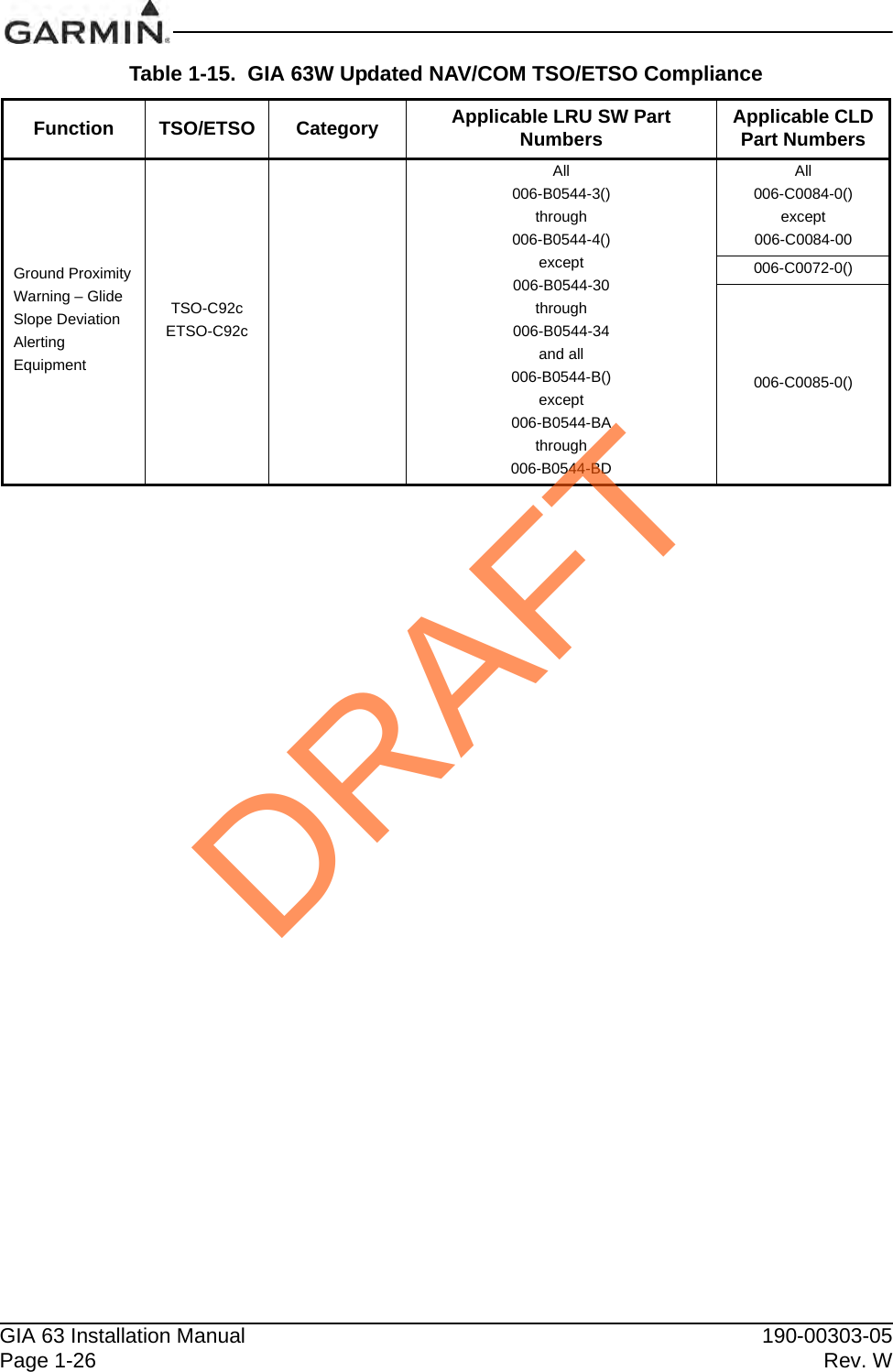
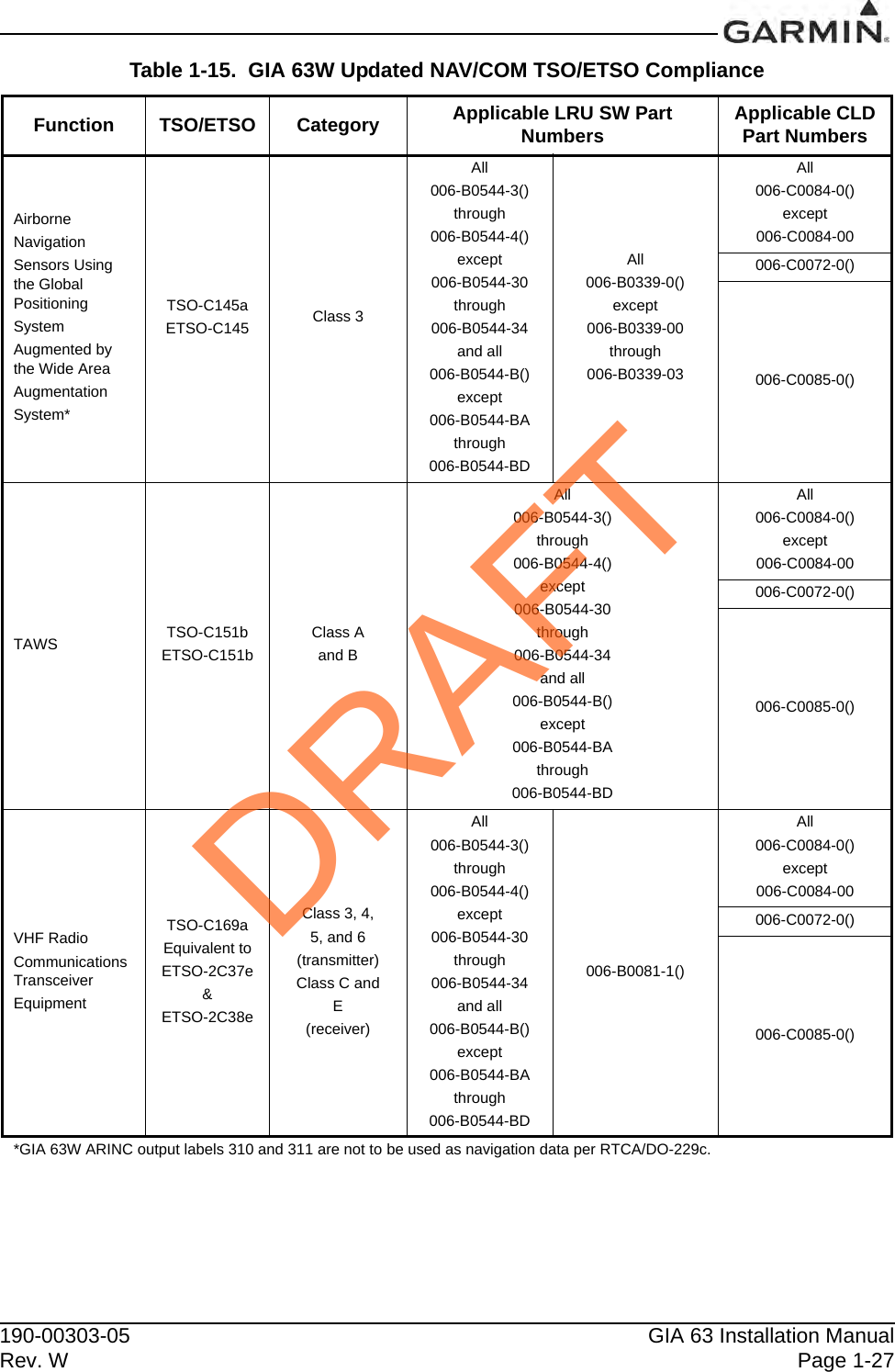
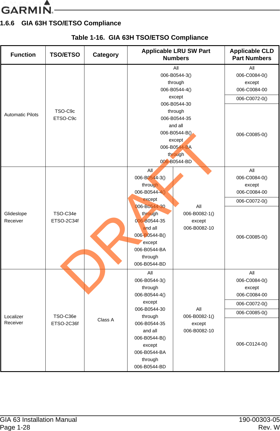
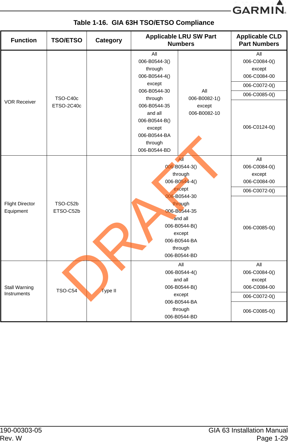
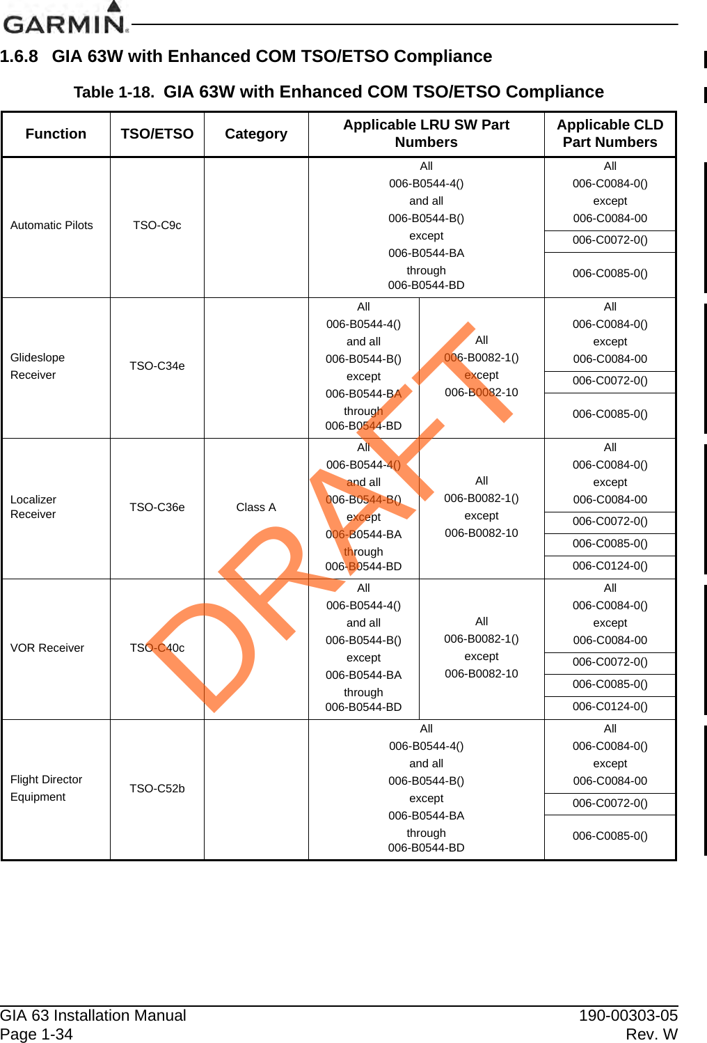
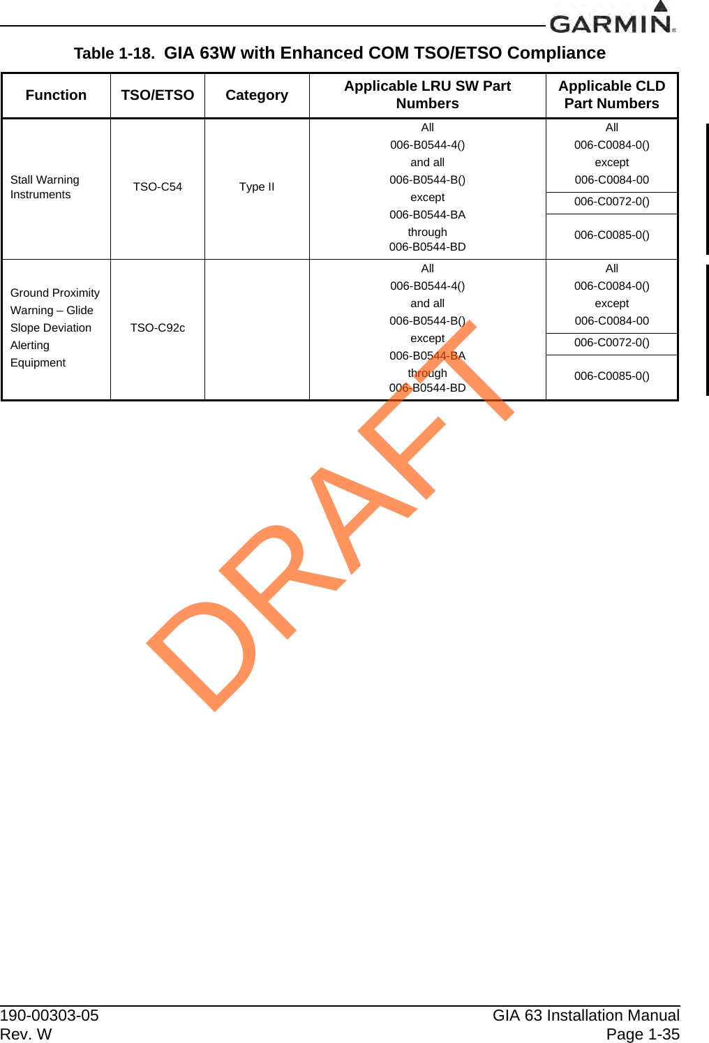
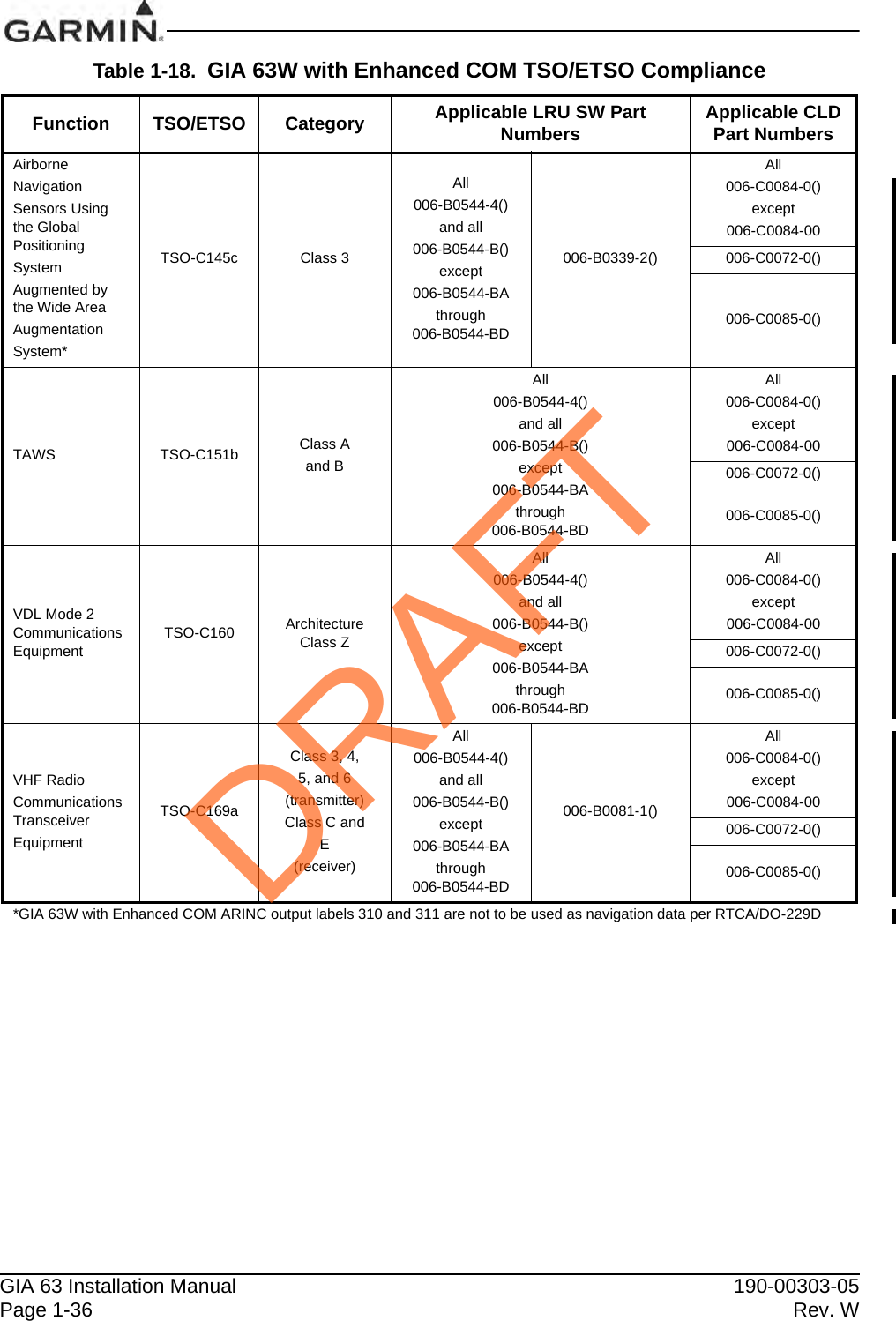
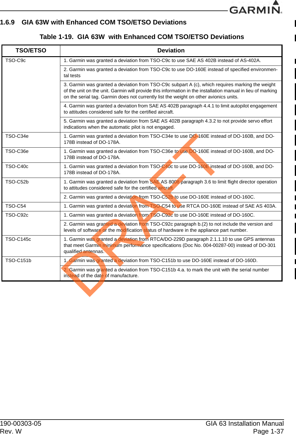

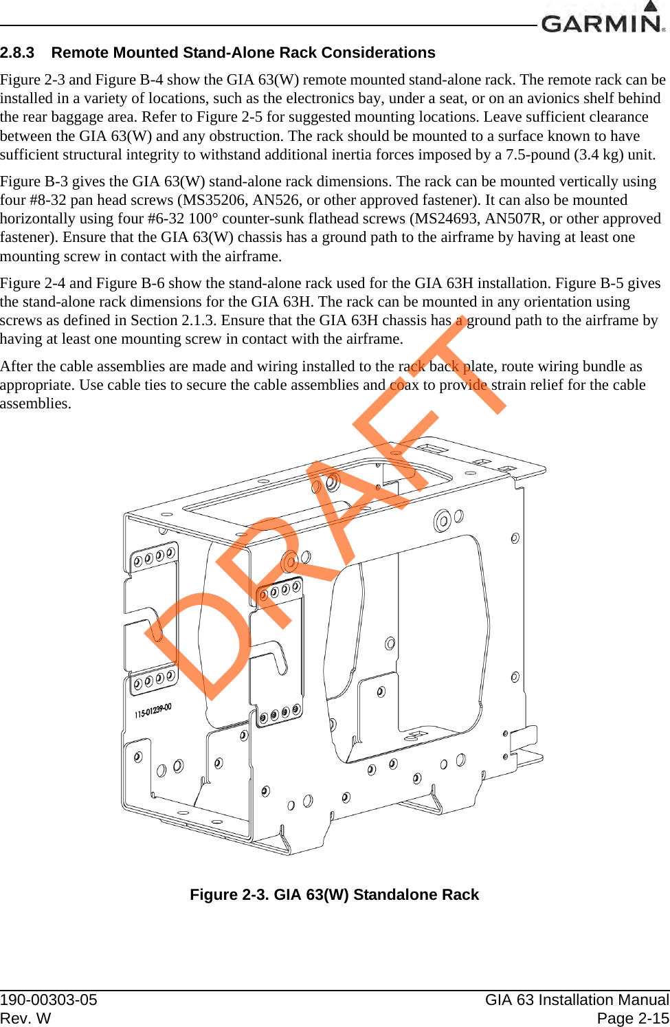
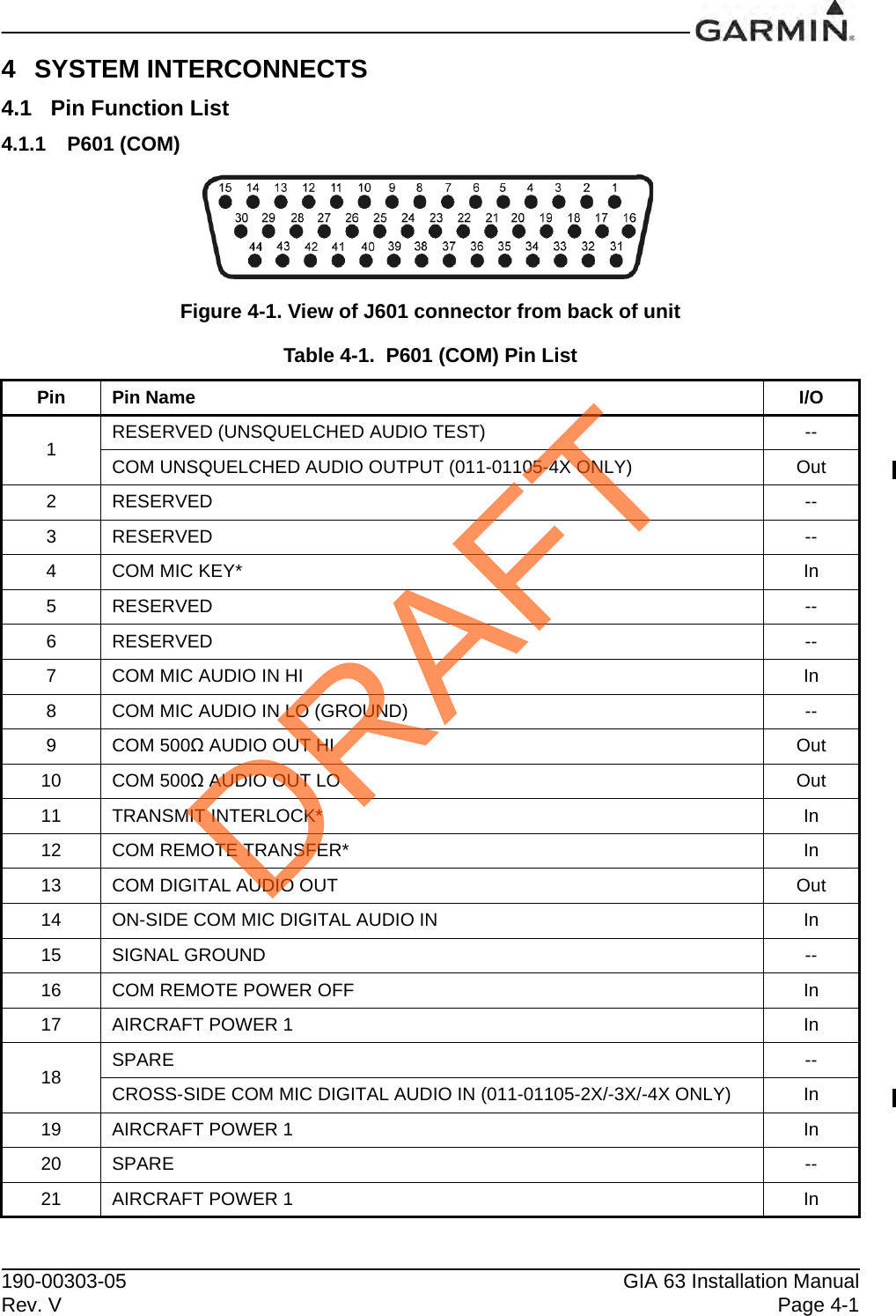
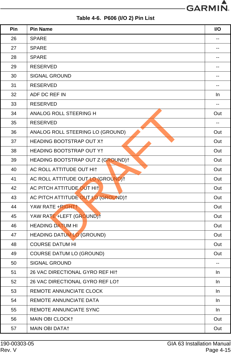
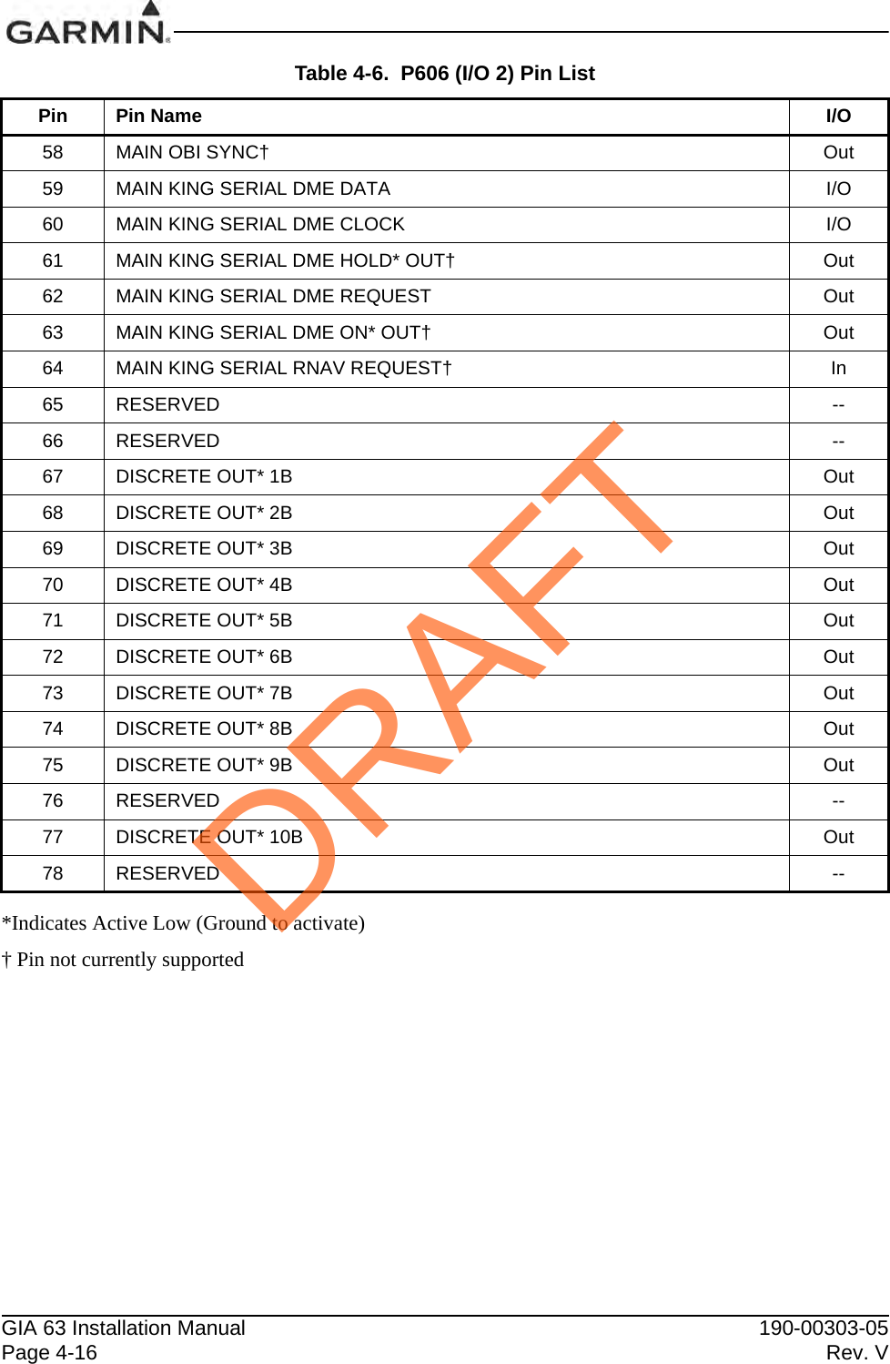
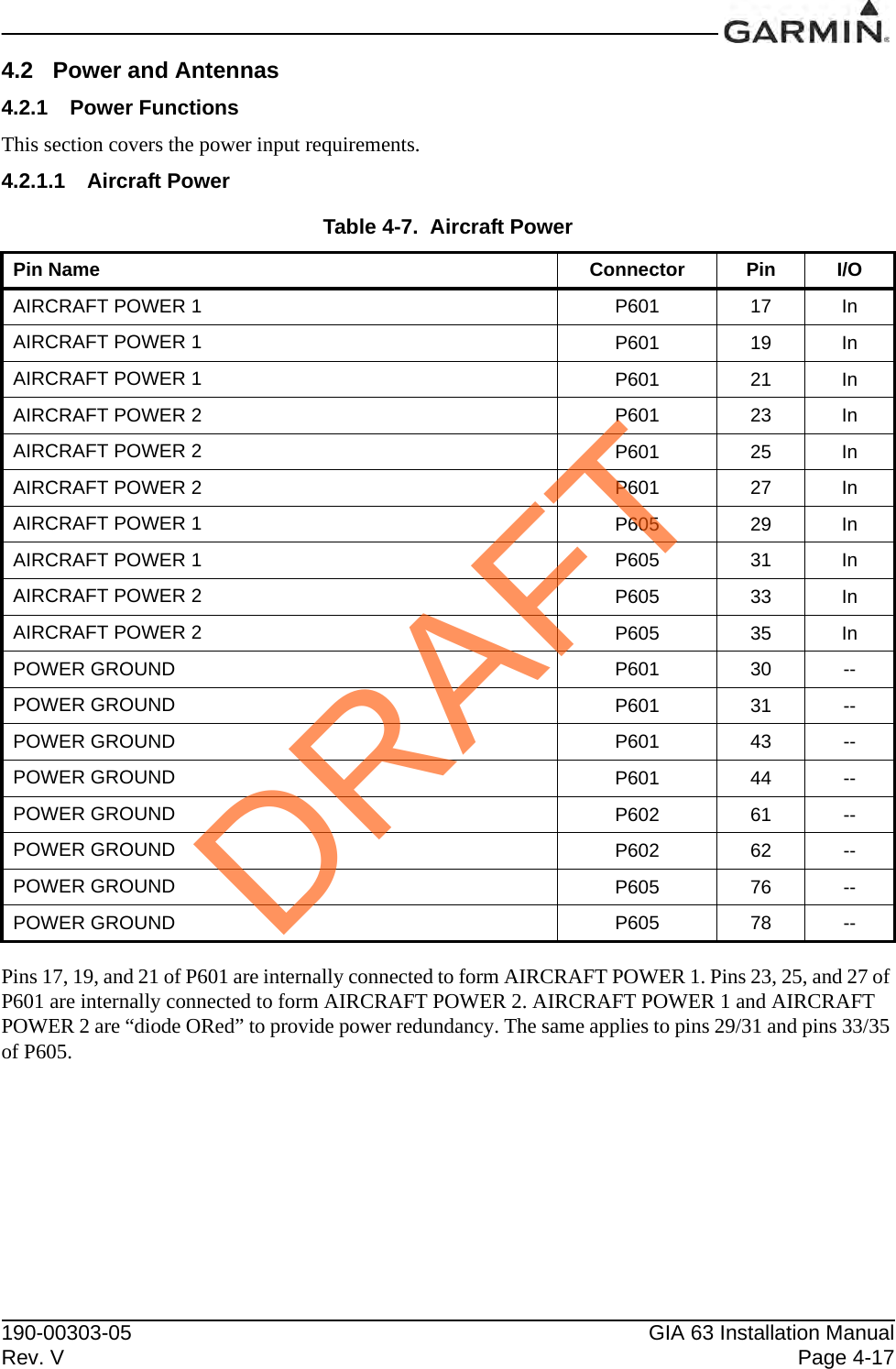
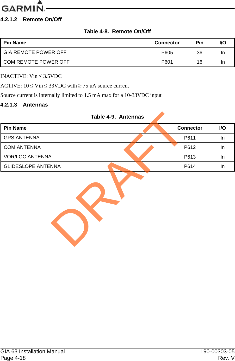
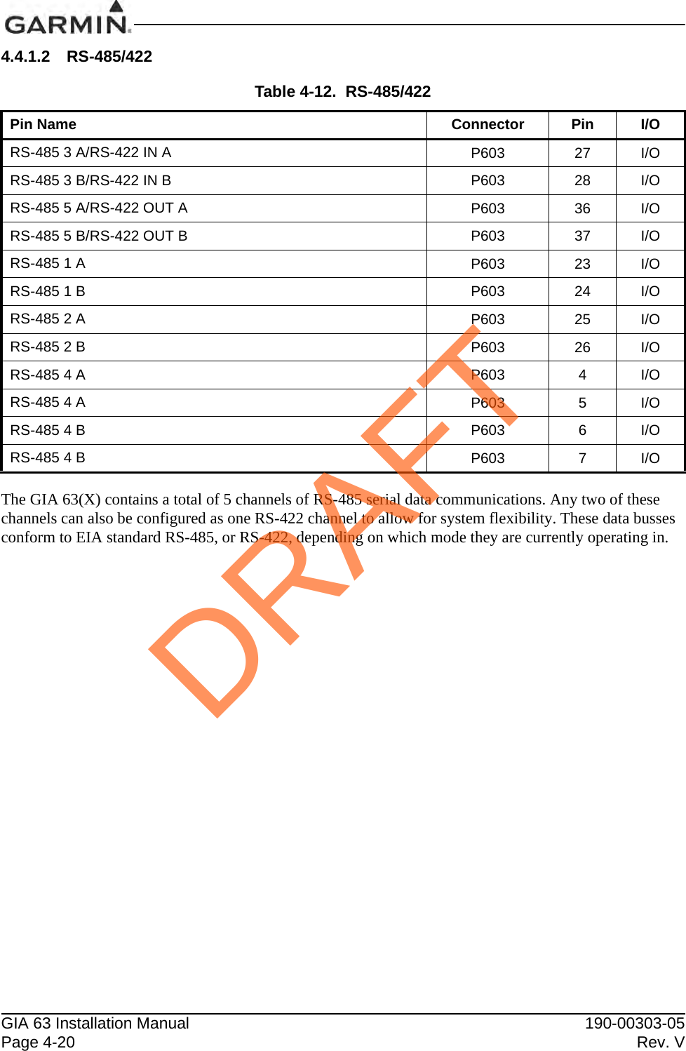
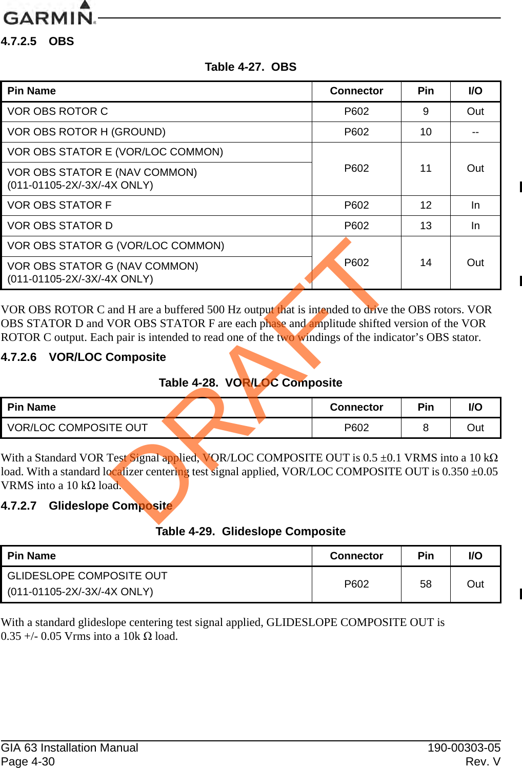
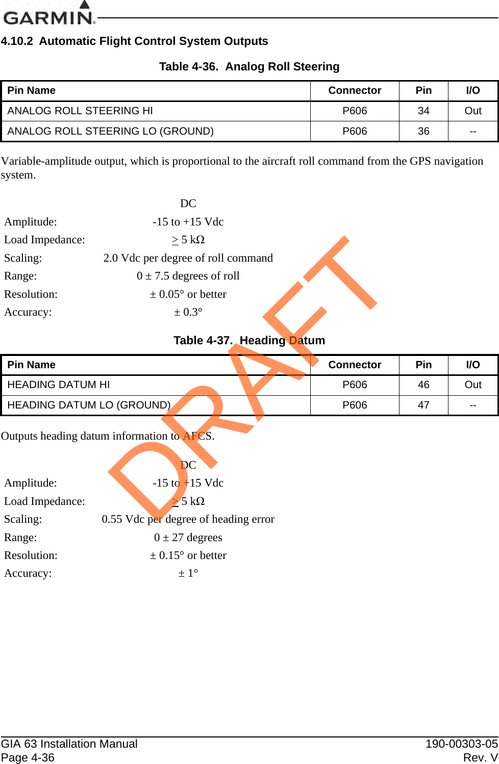
![190-00303-05 GIA 63 Installation ManualRev. W Page 1-411.6.10.2 GIA 63W and GIA 63H GPS Software Versions 3.2 or LaterThe following information may be used as guidance in developing an approved AFM, RFM, AFMS, RFMS, and/or POH provided the system is installed in accordance with [AC 20-138C] and is comprised of [two or more] [TSO-C145a Class 3 or TSO-C145c Class 3] approved Garmin GIA 63Ws or GIA 63Hs, [two or more] [TSO-C146a Class 3 or TSO-C146c Class 3] approved Garmin GDU 1XXX Display Units, Garmin-approved GPS/SBAS antennas (refer to Section 2.1.3.2), and GPS software version [3.2 or later approved version]:NOTEText contained in brackets “[ ]” is meant to serve as an example and will need to be modified in order to reflect the actual installation.GARMIN GNSS (GPS/SBAS) NAVIGATION SYSTEM EQUIPMENT APPROVALSThe Garmin GNSS navigation system is a GPS system with a Satellite Based Augmentation System (SBAS) comprised of [two or more] [TSO-C145a Class 3 or TSO-C145c Class 3] approved Garmin GIA 63Ws or GIA 63Hs, [two or more] [TSO-C146a Class 3 or TSO-C146c Class 3] approved Garmin GDU 1XXX Display Units, Garmin-approved GPS/SBAS antennas (refer to Section 2.1.3.2), and GPS software version [3.2 or later approved version]. The Garmin GNSS navigation system in this aircraft is installed in accordance with [AC 20-138C].The Garmin GNSS navigation system as installed in this aircraft complies with the requirements of [AC 20-138C] and has airworthiness approval for navigation using GPS and SBAS (within the coverage of a Satellite Based Augmentation System complying with ICAO Annex 10) for IFR en route, terminal area, and non-precision approach operations (including those approaches titled “GPS”, “or GPS”, and “RNAV (GPS)” approaches). The Garmin GNSS navigation system is approved for approach procedures with vertical guidance including “LPV” and “LNAV/VNAV”, within the U.S. National Airspace System.The Garmin GNSS navigation system complies with the equipment requirements of AC 90-105 and meets the equipment performance and functional requirements to conduct RNP terminal departure and arrival procedures and RNP approach procedures without RF (radius to fix) legs. Part 91 subpart K, 121, 125, 129, and 135 operators require operational approval from the FAA.The Garmin GNSS navigation system complies with the equipment requirements of AC 90-100A for RNAV 2 and RNAV 1 operations. In accordance with AC 90-100A, Part 91 operators (except subpart K) following the aircraft and training guidance in AC 90-100A are authorized to fly RNAV 2 and RNAV 1 procedures. Part 91 subpart K, 121, 125, 129, and 135 operators require operational approval from the FAA.The Garmin GNSS navigation system has been found to comply with the requirements for GPS Class II oceanic and remote navigation (RNP-10) without time limitations in accordance with [AC 20-138C] and FAA Order [8400.12C]. The Garmin GNSS navigation system can be used without reliance on other long-range navigation systems. This does not constitute an operational approval.The Garmin GNSS navigation system has been found to comply with the navigation requirements for GPS Class II oceanic and remote navigation (RNP-4) in accordance with [AC 20-138C] and FAA Order 8400.33. The Garmin GNSS navigation system can be used without reliance on other long-range navigation systems. Additional equipment may be required to obtain operational approval to utilize RNP-4 performance. This does not constitute an operational approval.DRAFT](https://usermanual.wiki/Garmin/0194500/User-Guide-1847191-Page-51.png)
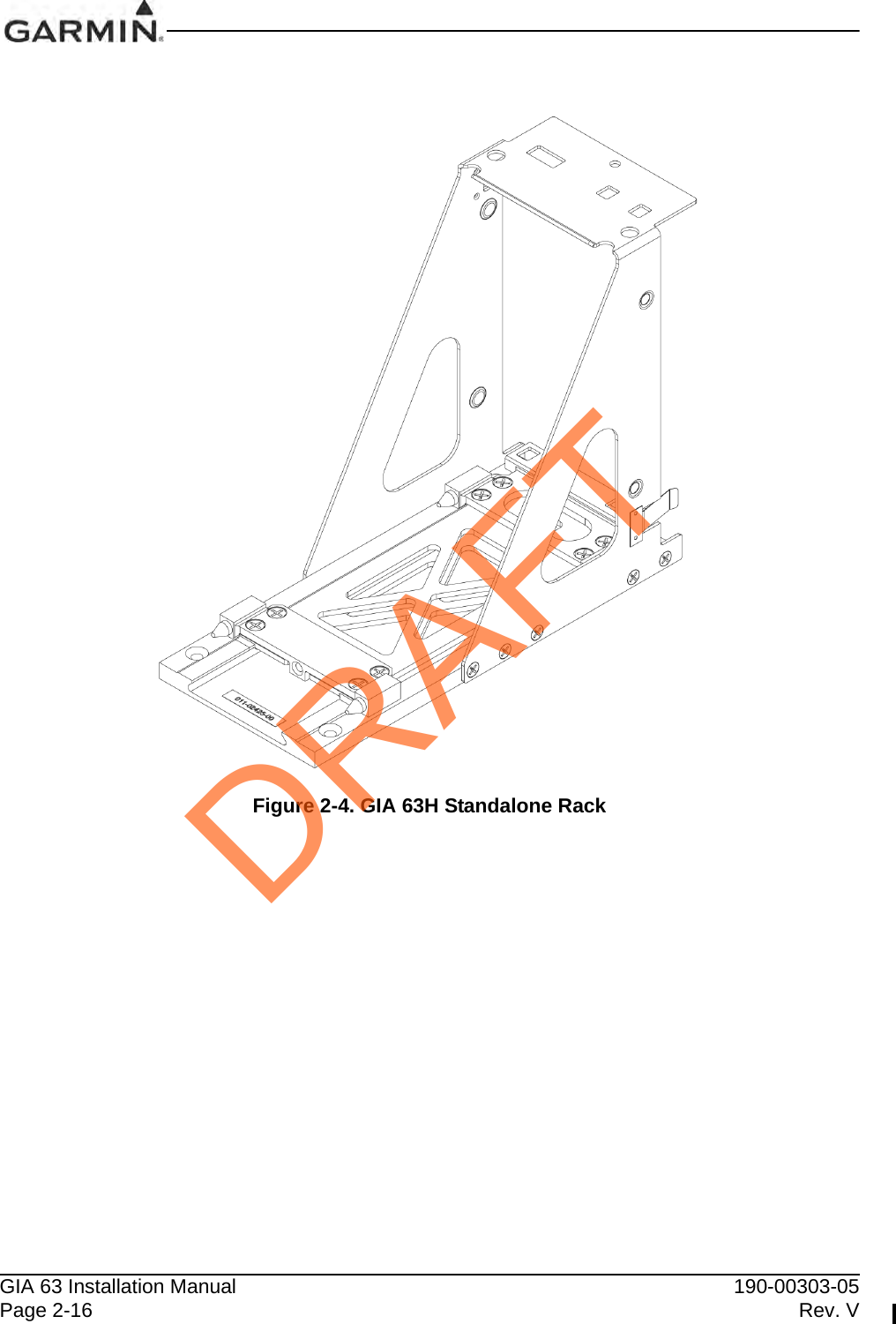
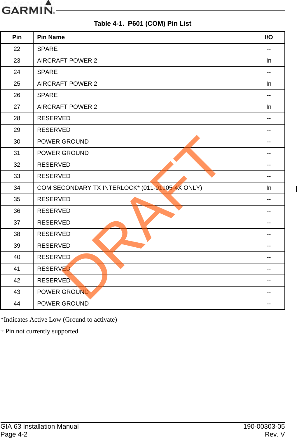
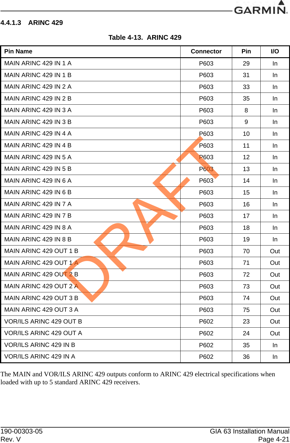
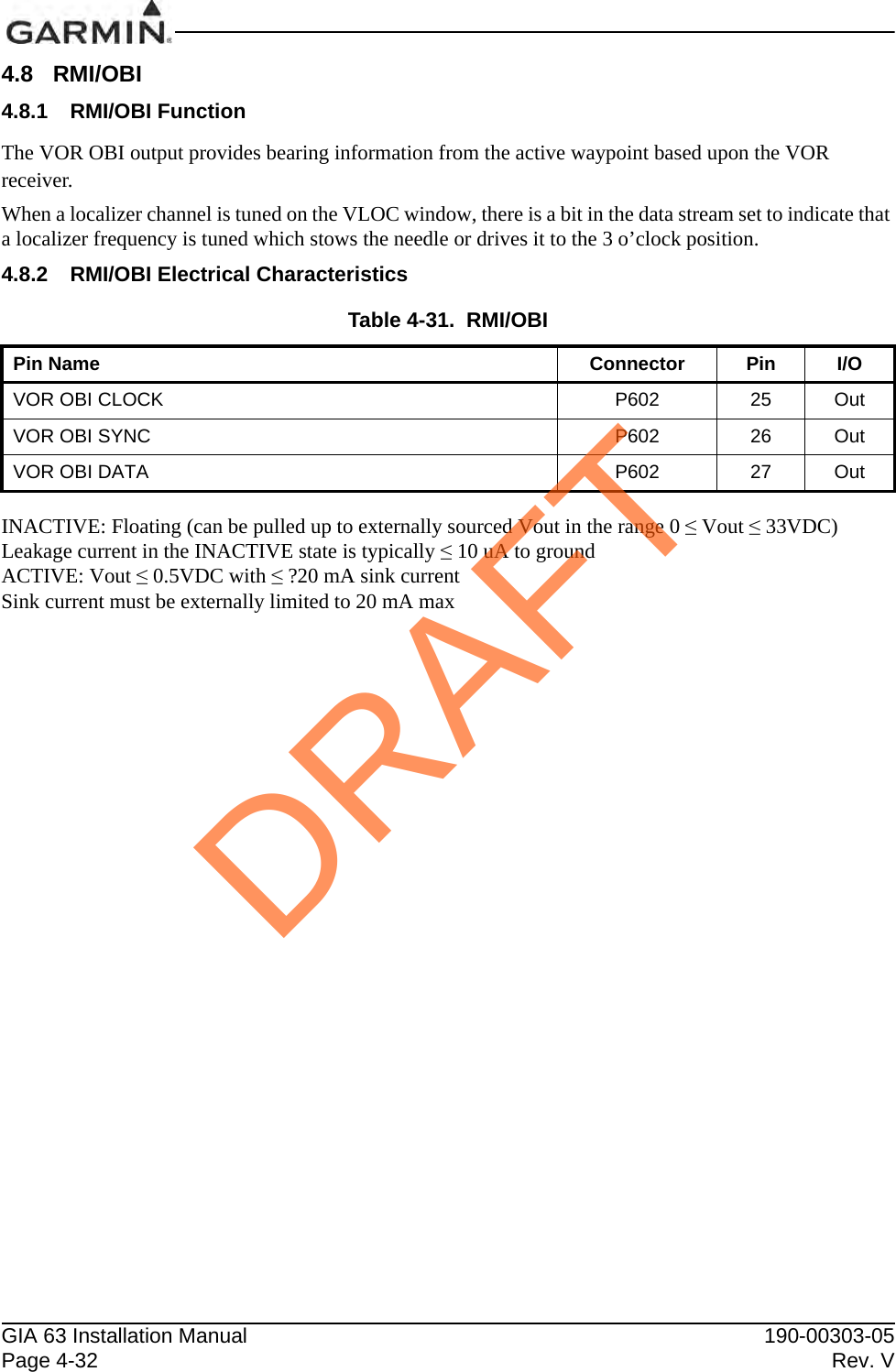
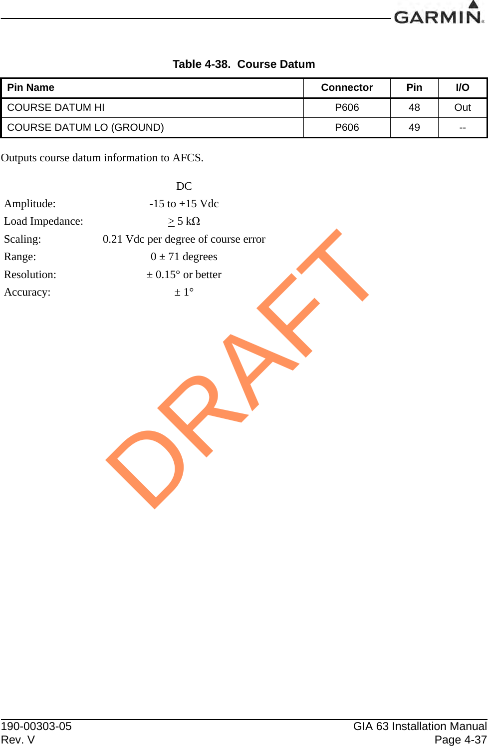
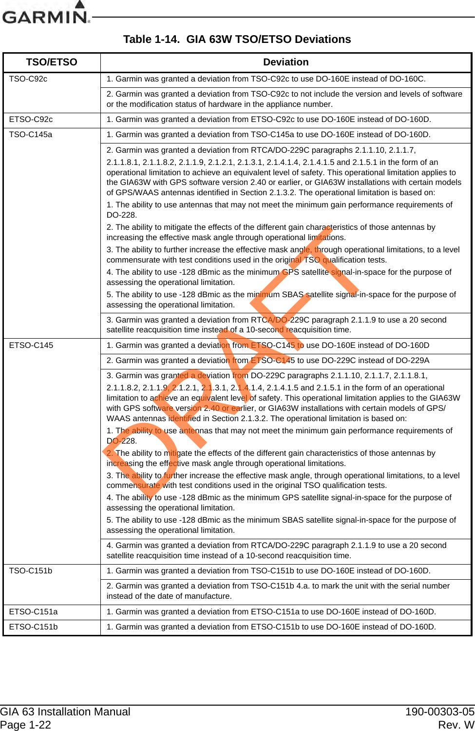
![GIA 63 Installation Manual 190-00303-05Page 1-42 Rev. WThe Garmin GNSS navigation system complies with the accuracy, integrity, and continuity of function, and contains the minimum system functions required for P-RNAV operations in accordance with JAA Administrative & Guidance Material Section One: General Part 3: Temporary Guidance Leaflets, Leaflet No 10 (JAA TGL-10 Rev 1). The GNSS navigation system has [two or more] [ETSO-C145 Class 3 or ETSO-C145c Class 3 / TSO-C145a Class 3 or TSO-C145c Class 3] approved Garmin GIA 63Ws or GIA 63Hs, and [two or more] [ETSO-146 Class 3 or ETSO-C146c Class 3 / TSO-C146a Class 3 or TSO-C146c Class 3] approved Garmin GDU 1XXX Display Units. The Garmin GNSS navigation system complies with the equipment requirements for P-RNAV and B-RNAV/RNAV 5 operations in accordance with AC 90-96A CHG 1 and JAA TGL-10 Rev 1. This does not constitute an operational approval.Garmin International holds an FAA Type 2 Letter of Acceptance (LOA) in accordance with [AC 20-153A] for database integrity, quality, and database management practices for the Navigation database. Flight crews and operators can view the LOA status at FlyGarmin.com then select “Type 2 LOA Status”.Navigation information is referenced to WGS-84 reference system.DRAFT](https://usermanual.wiki/Garmin/0194500/User-Guide-1847191-Page-52.png)
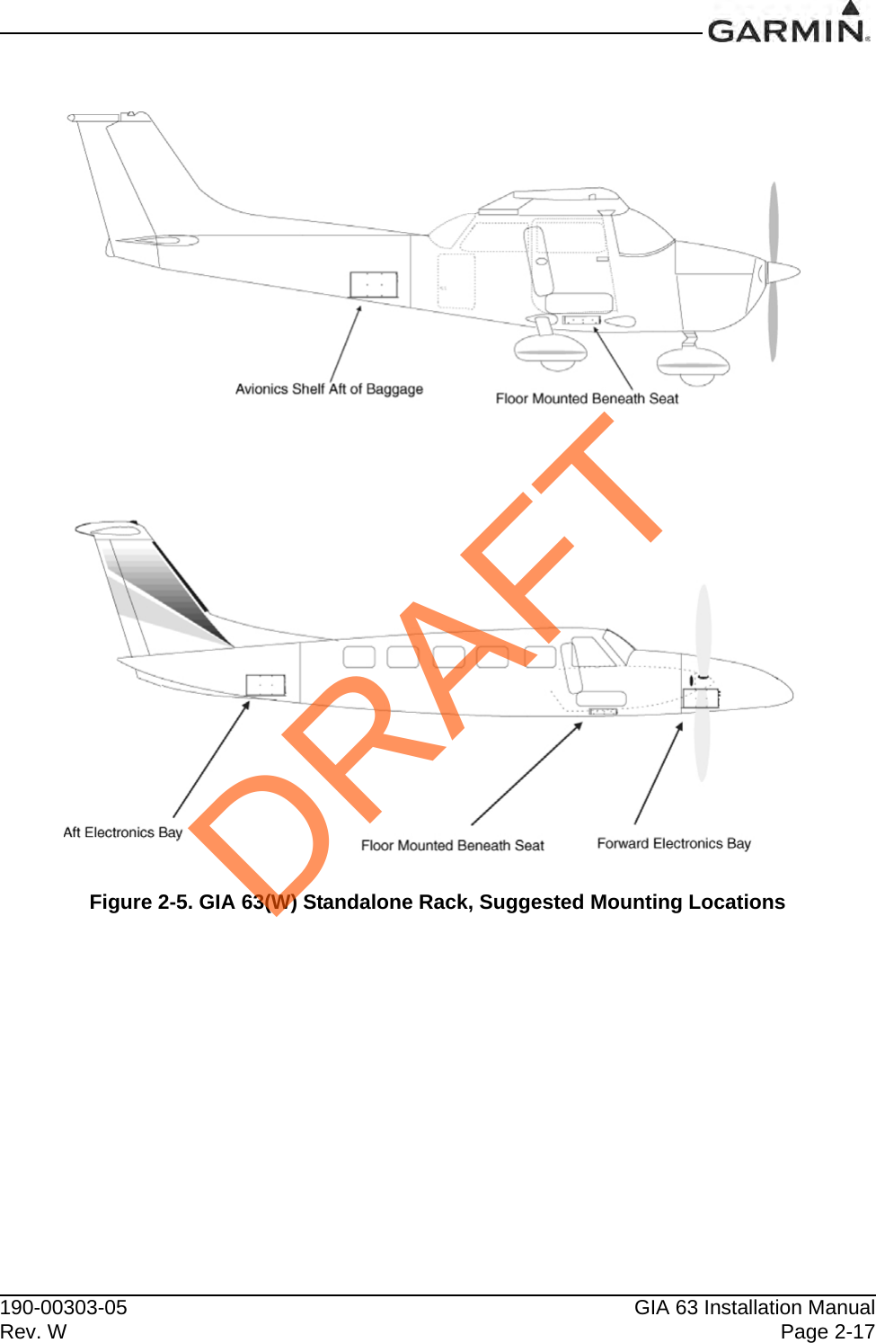
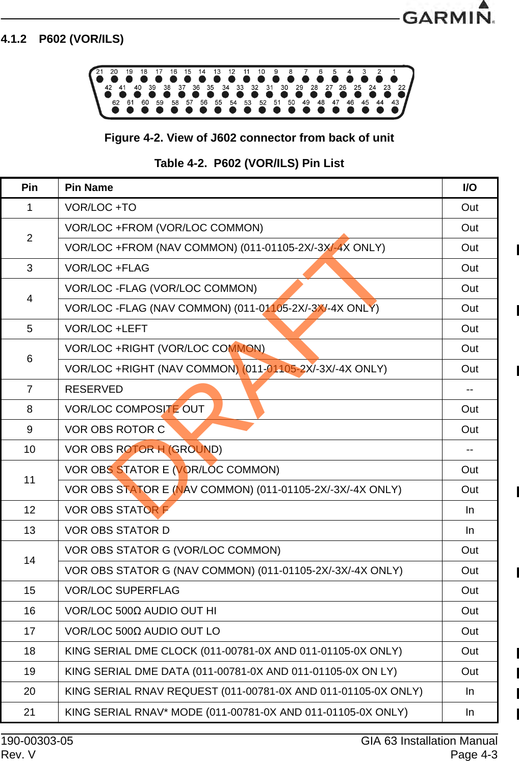
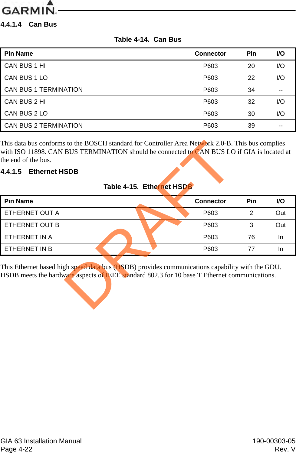
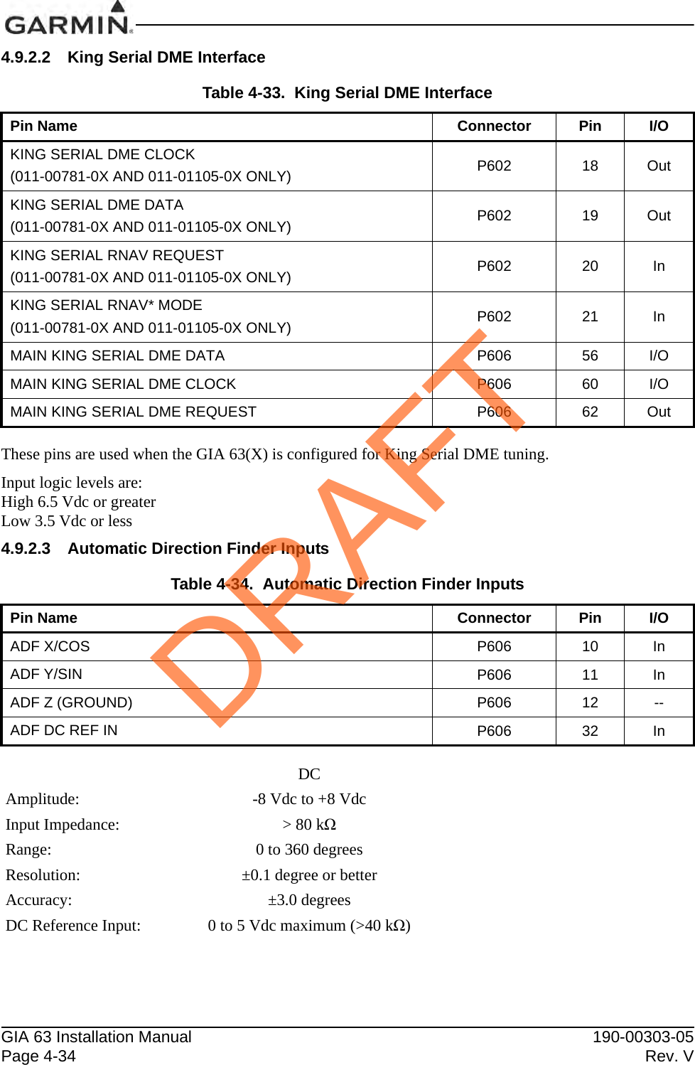
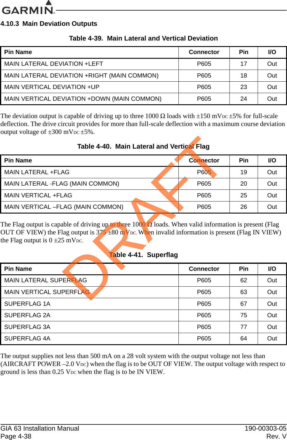
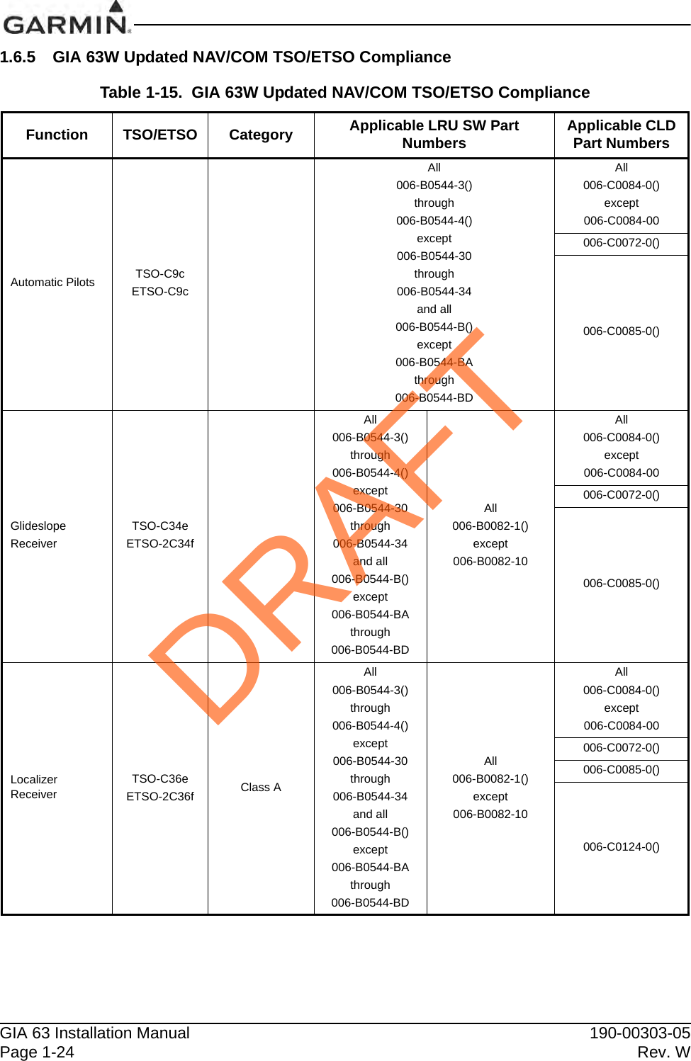
![190-00303-05 GIA 63 Installation ManualRev. W Page 1-43GARMIN GNSS (GPS/SBAS) NAVIGATION SYSTEM LIMITATIONSThe flight crew must confirm at system initialization that the Navigation database is current. Navigation database is expected to be current for the duration of the flight. If the AIRAC cycle will change during flight, the flight crew must ensure the accuracy of navigation data, including suitability of navigation facilities used to define the routes and procedures for flight. If an amended chart affecting navigation data is published for the procedure, the database must not be used to conduct the procedure.GPS/SBAS based IFR en route, oceanic, and terminal navigation is prohibited unless the flight crew verifies and uses a valid, compatible, and current Navigation database or verifies each waypoint for accuracy by reference to current approved data.Discrepancies that invalidate a procedure must be reported to Garmin International. The affected procedure is prohibited from being flown using data from the Navigation database until a new Navigation database is installed in the aircraft and verified that the discrepancy has been corrected. Navigation database discrepancies can be reported at FlyGarmin.com then select “Aviation Data Error Report”. Flight crew and operators can view Navigation data base alerts at FlyGarmin.com then select “NavData Alerts”.For flight planning purposes, in areas where SBAS coverage is not available, the flight crew must check RAIM availability. Within the United States, RAIM availability can be determined using the Garmin WFDE Prediction program, [part number 006-A0154-01 (included in G1000 trainer software) version 3.00 or later approved version with GARMIN GA36 and GA37 antennas selected], or the FAA’s en route and terminal RAIM prediction website: www.raimprediction.net, or by contacting a Flight Service Station. Within Europe, RAIM availability can be determined using the Garmin WFDE Prediction program or Europe’s AUGER GPS RAIM Prediction Tool at http://augur.ecacnav.com/augur/app/home. For other areas, use the Garmin WFDE Prediction program. This requirement is not necessary if SBAS coverage is confirmed to be available along the entire route of flight. The route planning and WFDE prediction program may be downloaded from the Garmin website on the internet. For information on using the WFDE Prediction Program, refer to Garmin WAAS FDE Prediction Program, part number 190-00643-01, ‘WFDE Prediction Program Instructions’.For flight planning purposes, operations within the U.S. National Airspace System on RNP and RNAV procedures when SBAS signals are not available, the availability of GPS RAIM shall be confirmed for the intended route of flight. In the event of a predicted continuous loss of RAIM of more than five minutes for any part of the intended route of flight, the flight should be delayed, canceled, or re-routed on a track where RAIM requirements can be met.For flight planning purposes for operations within European B-RNAV/RNAV-5 and P-RNAV airspace, if more than one satellite is scheduled to be out of service, then the availability of GPS RAIM shall be confirmed for the intended flight (route and time). In the event of a predicted continuous loss of RAIM of more than five minutes for any part of the intended flight, the flight should be delayed, canceled, or rerouted on a track where RAIM requirements can be met.For flight planning purposes, operations where the route requires Class II navigation the aircraft’s operator or flight crew must use the Garmin WFDE Prediction program to demonstrate that there are no outages on the specified route that would prevent the Garmin GNSS navigation system from providing GPS Class II navigation in oceanic and remote areas of operation that requires (RNP-10 or RNP-4) capability. If the Garmin WFDE Prediction program indicates fault exclusion (FDE) is unavailable for more than 34 minutes in accordance with FAA Order 8400.12C for RNP-10 requirements, or 25 minutes in accordance with FAA Order 8400.33 for RNP-4 requirements, then the operation must be rescheduled when FDE is available.DRAFT](https://usermanual.wiki/Garmin/0194500/User-Guide-1847191-Page-53.png)
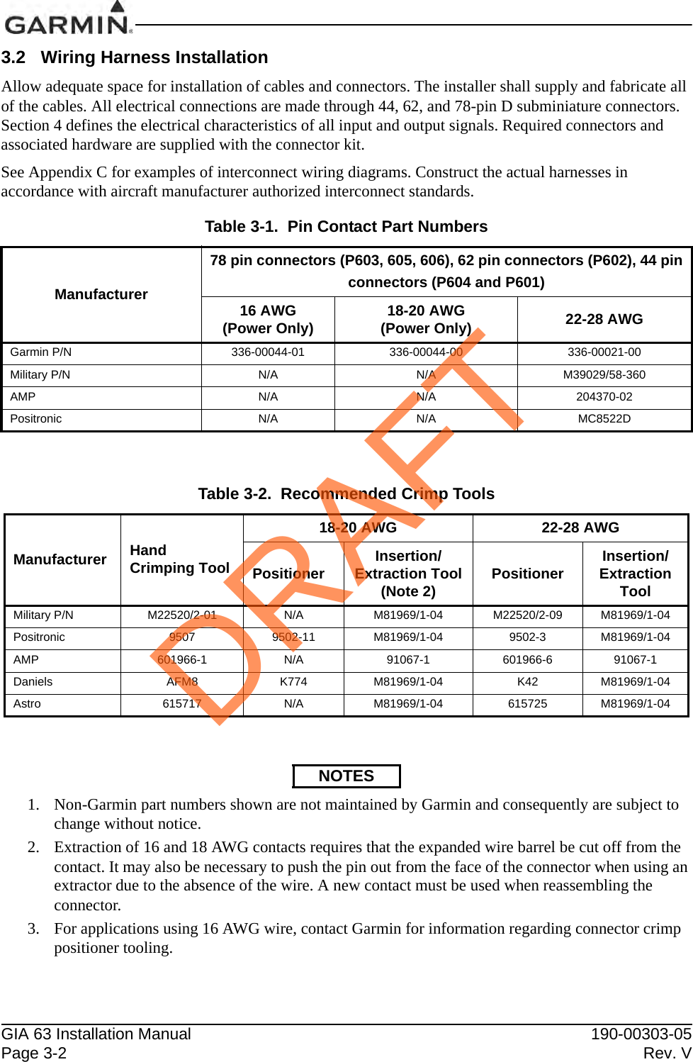
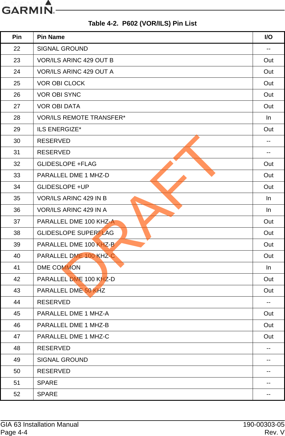
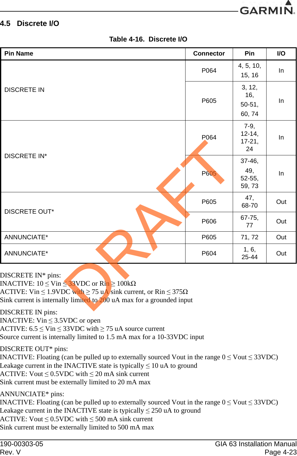
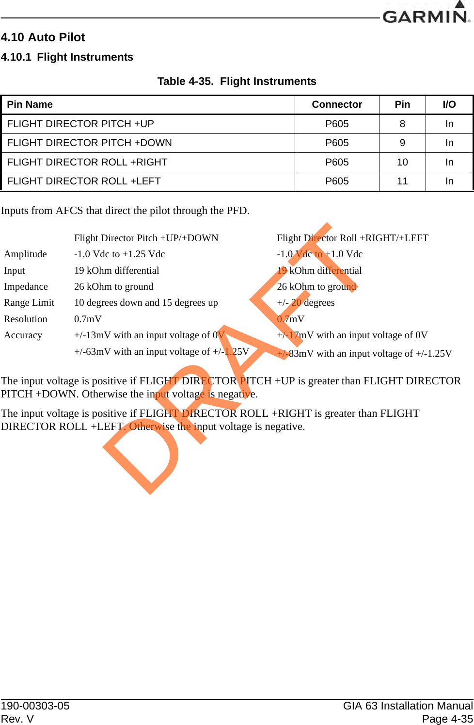
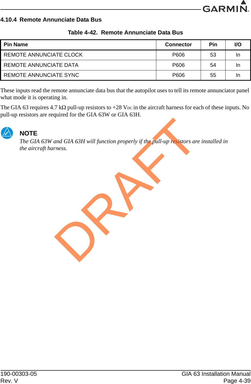
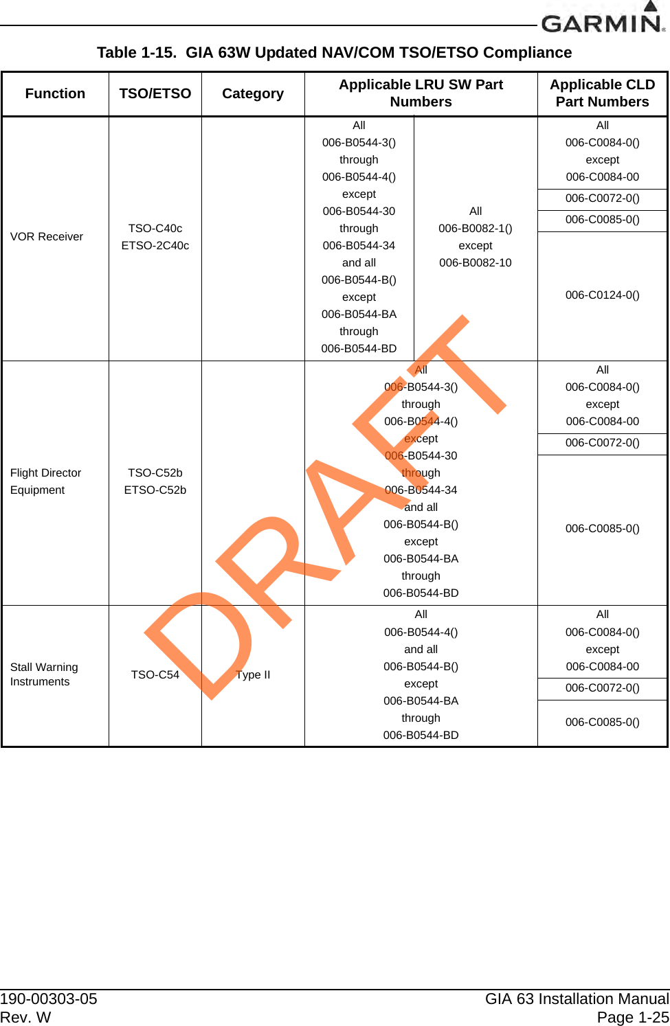
![GIA 63 Installation Manual 190-00303-05Page 1-44 Rev. WBoth Garmin GPS navigation receivers must be operating and providing GPS navigation guidance to their respective PFD for operations requiring RNP-4 performance.North Atlantic (NAT) Minimum Navigational Performance Specifications (MNPS) Airspace operations per AC 91-49 and AC 120-33 require both GPS/SBAS receivers to be operating and receiving usable signals except for routes requiring only one Long Range Navigation sensor. Each display computes an independent navigation solution based on the on-side GPS sensor. However, either display will automatically revert to the cross-side sensor if the on-side sensor fails or if the cross-side sensor is determined to be more accurate. [On G1000 installations a “BOTH ON GPS1” or “BOTH ON GPS2” message does not necessarily mean that one GPS has failed. Refer to the MFD AUX-GPS STATUS page to determine the state of the unused GPS].Whenever possible, RNP and RNAV routes including Standard Instrument Departures (SIDs) and Obstacle Departure Procedures (ODPs), Standard Terminal Arrival (STAR), and en route RNAV “Q” and RNAV “T” routes should be loaded into the flight plan from the database in their entirety, rather than loading route waypoints from the database into the flight plan individually. Selecting and inserting individual named fixes from the database is permitted, provided all fixes along the published route to be flown are inserted. Manual entry of waypoints using latitude/longitude or place/bearing is prohibited.“GPS”, “or GPS”, and “RNAV (GPS)” instrument approaches using the Garmin navigation systems are prohibited unless the flight crew verifies and uses the current Navigation database. GPS based instrument approaches must be flown in accordance with an approved instrument approach procedure that is loaded from the Navigation database.Not all published Instrument Approach Procedures (IAP) are in the Navigation database. Flight crew planning on flying an RNAV instrument approach must ensure that the Navigation database contains the planned RNAV Instrument Approach Procedure and that approach procedure must be loaded from the Navigation database into the FMS flight plan by its name.IFR non-precision approach approval using the GPS/SBAS sensor is limited to published approaches within the U.S. National Airspace System. Approaches to airports in other airspace are not approved unless authorized by the appropriate governing authority.The navigation equipment required to join and fly an instrument approach procedure is indicated by the title of the procedure and notes on the IAP chart. Use of the Garmin GPS/SBAS receivers to provide navigation guidance during the final approach segment of an ILS, LOC, LOC-BC, LDA, SDF, MLS or any other type of approach not approved for “or GPS” navigation is prohibited. When using the Garmin VOR/LOC/GS receivers to fly the final approach segment, VOR/LOC/GS navigation data must be selected and presented on the CDI of the pilot flying.Navigation information is referenced to WGS-84 reference system, and should only be used where the Aeronautical Information Publication (including electronic data and aeronautical charts) conform to WGS-84 or equivalent.DRAFT](https://usermanual.wiki/Garmin/0194500/User-Guide-1847191-Page-54.png)


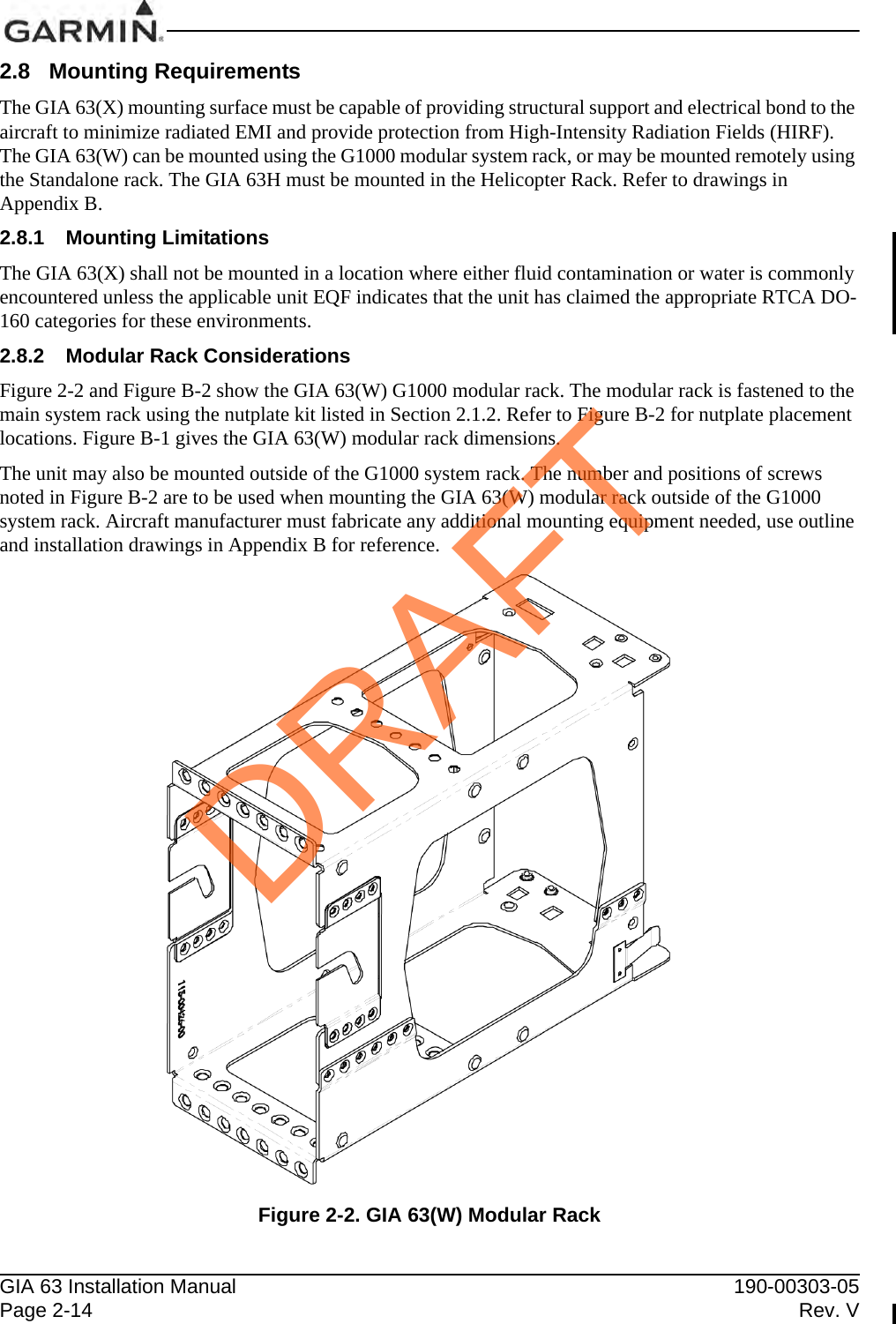
![190-00303-05 GIA 63 Installation ManualRev. W Page 2-32.1.3 Additional Equipment RequiredThe following installation accessories are required but not provided:COM Antenna: Shall meet TSO-C169()*, or shall meet both TSO-C37() and C38(), Broad band, 50 Ω, vertically polarized with coaxial cableGPS Antenna: GIA 63 (011-00781-0X) shall meet TSO-C129a. TSO-C144 antennas can also meet TSO-C129a requirements for the GIA 63 (Refer to Section 2.1.3.1).GIA 63H and GIA 63W (011-01105-0X/-2X/-3X) shall meet TSO-C144 and additional system requirements specified by TSO-C145a. Refer to Section 2.1.3.2 for approved antennasGIA 63W (011-01105-4X) shall meet TSO-C144 and additional system requirements specified by TSO-C145c. Refer to Section 2.1.3.2 for approved antennasVOR/LOC Antenna: Shall meet TSO-C40() and C36(). Broad band, 50 Ω, horizontally polarized with coaxial cableGlideslope Antenna: Shall meet TSO-C34(). Broad band, 50 Ω, horizontally polarized with coaxialcable or low-loss splitter used with the VOR/LOC antennaHeadphones: 500 Ω nominal impedance Microphone: Low impedance, carbon or dynamic,with transistorized pre-ampHardware: #6-32 x 100°Flathead SS Screw [(MS24693, AN507R or other approved fastener) (4 ea.)] for horizontal mounting of the standalone rack.Hardware: #8-32 Panhead Machine Screw [(MS35206, AN526 or other approvedfastener) (4 ea.)] for vertical mounting of the standalone rack.Hardware: #10-32 x 100°Flathead Screw [(MS24694S51 or screw of same or greater strength)(4 ea.)] for mounting of the helicopter rack.*GIA 63W and GIA 63H only2.1.3.1 Required Antenna for the GIA 63Antennas used with the GIA 63 (non-WAAS) must meet the antenna specifications shown in Section 2.6. In addition, TSO-C144 antennas can also meet TSO-C129a requirements for the GIA 63 (non-WAAS) if their additional gain (which is about 16dB at 1.5 GHz for antennas produced by Garmin) is offset by added attenuation in-line with the GIA 63 (non-WAAS). If an in-line attenuator is used, it must pass DC current (40 mA max at 4.6 VDC) which is provided from the GPS receiver to the antenna pre-amplifier.2.1.3.2 Required WAAS Antennas for the GIA 63W and GIA 63HThe following is a list of TSO-C144 antennas that allow the GIA 63W and GIA 63H with GPS software version 3.2 or later to meet TSO-C145a requirements without requiring the operational limitations specified in Section 1.6.10.2 of this manual:DRAFT](https://usermanual.wiki/Garmin/0194500/User-Guide-1847191-Page-61.png)
![GIA 63 Installation Manual 190-00303-05Page 2-4 Rev. VTable 2-3. TSO-C145a WAAS Antennas for the GIA 63W and GIA 63HModel Mount Style Conn TypeSATCOM Compatible [3] Mfr Antenna Part Number Garmin Order Number Additional RequirementsGA 35 GPSWAAS Antenna [6]ScrewMount,TeardropFootprint [2]TNC YesAeroAntennaAT575-93GWTNCF-000-RG-27-NM 013-00235-00NoneGarmin 013-00235-00GA 36 GPSWAAS Antenna [6]ScrewMount,ARINC 743FootprintTNC YesAeroAntennaAT575-326GW-TNCF-000-RG-27-NM 013-00244-00Garmin 013-00244-00GA 37FIS/WAASAntenna [6]ScrewMount,ARINC 743FootprintTNC YesAeroAntennaAT2300-126GW-TNCF-000-RG-27-NM 013-00245-00Garmin 013-00245-00Comant 2580-200WAAS andCOMAntenna[6] [8]ScrewMount,TeardropFootprint [2]BNCTNC[5]Yes ComantCI 2580-200N/AComant 2580-410FIS/WAAS/COM Antenna[6] [8]CI 2580-410Comant 428-200WAAS Antenna[6] [8]ScrewMount,ARINC 743FootprintTNC Yes ComantCI 428-200N/AComant 428-410FIS/WAASAntenna[6][8]CI 428-410Comant 2728-200WAAS andCOM Antenna[6][8]ScrewMount,TeardropFootprint [7]BNCTNC[5]Yes ComantCI 2728-200N/AComant 2728-410FIS/WAAS/COM Antenna[6][8]CI 2728-410DRAFT](https://usermanual.wiki/Garmin/0194500/User-Guide-1847191-Page-62.png)
![190-00303-05 GIA 63 Installation ManualRev. W Page 2-5The following is a list of known TSO-C144 antennas that allow the GIA 63W and GIA 63H with any version of GPS software version to meet TSO-C145a requirements with the operational limitations specified in Section 1.6.4 and 1.6.7 of this manual:[1] Same footprint and mounting hole pattern as GA 56.[2] Same mounting hole pattern as the GA 56, but has a physically larger footprint.[3] SATCOM compatibility requirements are as specified by RTCA/DO-229C Section 2.5.6.1, Section 2.5.8.2, Appendix C.2.1, and Appendix C.2.2.[4] The WAAS GPS antenna connector is a BNC type. The XM antenna connector is a TNC type.[5] The WAAS GPS antenna connector (and XM antenna connector where applicable) is TNC type. The VHF COM antenna connector is BNC type.[6] Not approved for use with the GIA 63 (non-WAAS) since max DC current specification exceeds40 mA.[7] Larger footprint and mounting hole pattern than GA 56, GA 35 or CI 2580.[8] It is the installer’s responsibility to ensure the antenna complies with Antenna Minimum Performance Specification for Garmin’s GPS/WAAS Receiver System Antenna (004-00287-00) by communicating the requirement to the supplier and obtaining a certificate of compliance to 004-00287-00 from the supplier. An antenna that complies only with TSO-C144 requirements is not adequate for this installation.Other TSO-C144 antennas may meet the installation requirements of the GIA 63W and GIA 63H. Contact Garmin to ensure compatibility and applicable operation limitations before beginning the installation.Table 2-4. TSO-C144 WAAS Antennas for the GIA 63W and GIA 63HModel Mount Style Conn TypeSATCOM Compatible [3] Mfr Antenna Part Number Garmin Order Number Additional RequirementsA-34 GPSWAAS AntennaScrewMount,TeardropFootprint [2]TNC YesAeroAntennaAT575-93WTNCF-000-05-26-NM 013-00113-00The operationallimitationdescribed inSection 1.6.4and 1.6.7requires use of006-A0154-01as the Predic-tionProgram inconjunction withthese antennas.Garmin AT 590-1112GA56A GPSWAAS AntennaScrewMount,ARINC 743FootprintBNC No Garmin 011-01154-00 010-10599-00GA56W GPSWAAS AntennaStud Mount,TeardropFootprint [1]BNC No Garmin 011-01111-00 010-10561-01GA57 GPSWAAS and FISAntennaScrewMount,ARINC 743FootprintBNCTNC[4]No Garmin 011-01032-00 010-10604-00DRAFT](https://usermanual.wiki/Garmin/0194500/User-Guide-1847191-Page-63.png)