Garmin 0194500 AIRBORNE COMMUNICATIONS TRANSCEIVER User Manual
Garmin International Inc AIRBORNE COMMUNICATIONS TRANSCEIVER Users Manual
Garmin >
Users Manual
190-00303-05 November, 2012 Revision W
GIA 63
Installation Manual
DRAFT
190-00303-05 GIA 63 Installation Manual
Rev. W Page A
© Copyright 2012
Garmin Ltd. or its subsidiaries
All Rights Reserved
Except as expressly provided herein, no part of this manual may be reproduced, copied, transmitted, disseminated, downloaded or
stored in any storage medium, for any purpose without the express prior written consent of Garmin. Garmin hereby grants permis-
sion to download a single copy of this manual and of any revision to this manual onto a hard drive or other electronic storage medium
to be viewed and to print one copy of this manual or of any revision hereto, provided that such electronic or printed copy of this
manual or revision must contain the complete text of this copyright notice and provided further that any unauthorized commercial
distribution of this manual or any revision hereto is strictly prohibited.
Garmin International, Inc.
1200 E. 151st Street
Olathe, KS 66062 USA
Telephone: 913-397-8200
Aviation Dealer Technical Support Line (Toll Free): (888) 606-5482
www.garmin.com
Garmin (Europe) Ltd
Liberty House
Bulls Copse Road
Hounsdown Business Park
Southampton, SO40 9RB, UK
Telephone: +44 (0) 8708501241
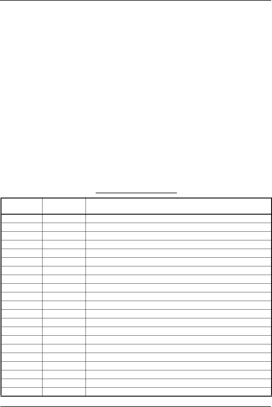
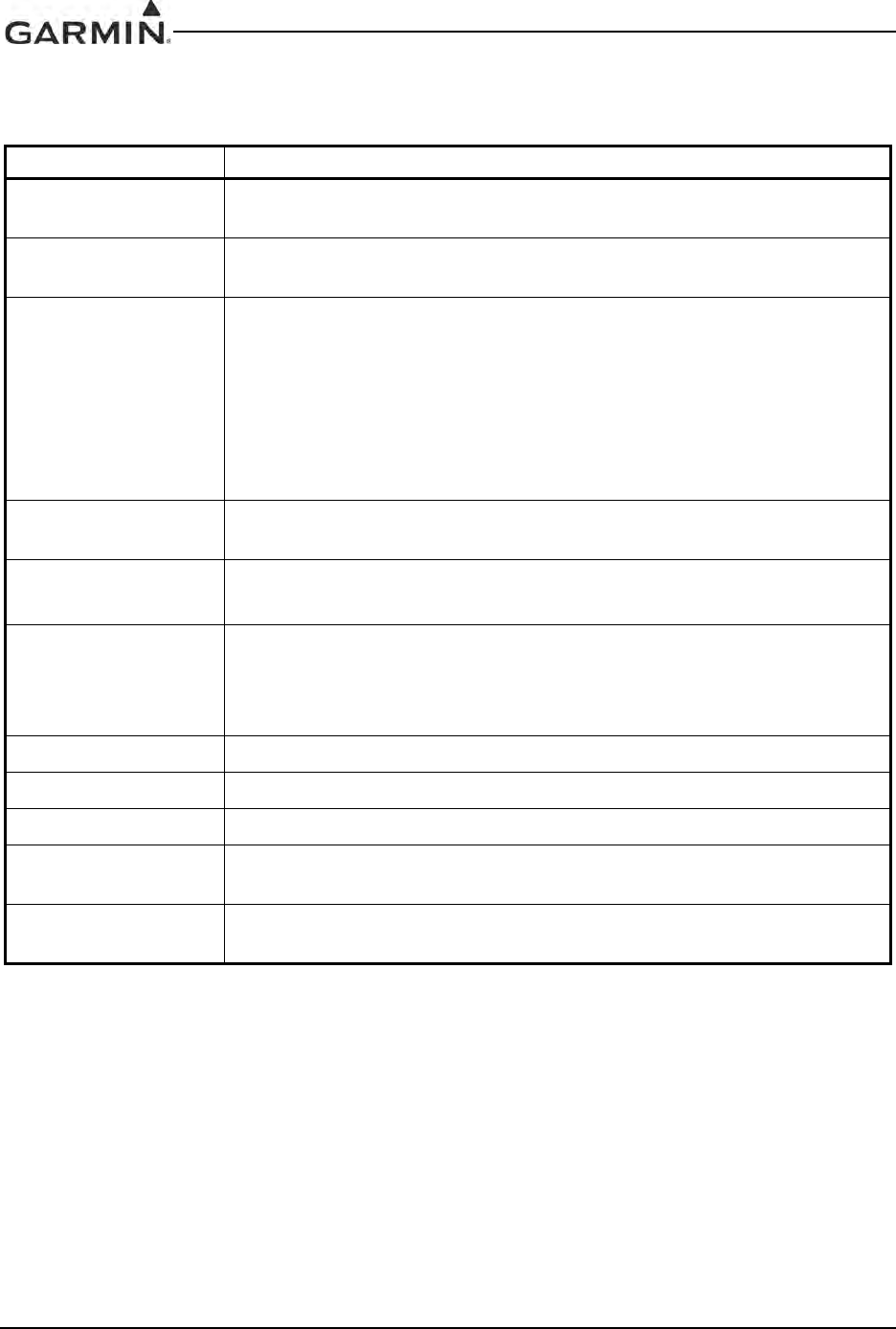
RECORD OF REVISIONS
Revision Revision
Date Description
A 11/15/04 Production Release
B 3/16/05 Updated pinout list, removed EQF and ETSO 2C37e deviation
C 6/23/05 Added additional interconnects, TSO-C9c, and TSO-C52b
D 10/26/05 Added TSO-C151b and boot block instructions
E 6/8/06 Edited document to include the GIA 63W
F 7/21/06 Corrected WAAS TSO
G 9/19/06 Added RTCA/DO-229C deviation
H 10/18/06 Added Comant antennas
J 4/10/07 Added Comant antenna and revised ICAW
K 6/6/07 Added the 011-01105-01 unit
L 8/23/07 Changed operational limitations and added antennas
M 2/29/08 Added ETSO information
N 5/27/09 Added TSO-C92c and other TSO info
P 9/09/09 Added Level A CLD information
Q 12/29/09 Added antenna note
R 3/23/10 Added standalone rack info
S 7/29/10 Added updated NAV/COM unit
T 11/24/10 Added GIA 63H model info, changed doc title
U 12/27/11 Added GIA 63W and 63H ETSOs
V 8/23/12 Added TSO-C54
W 11/12/12 Added -40 GIA 63W
DRAFT
190-00303-05 GIA 63 Installation Manual
Rev. W Page i
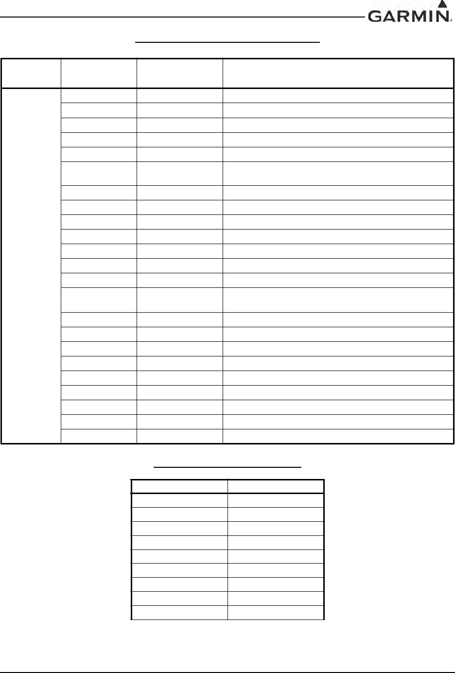
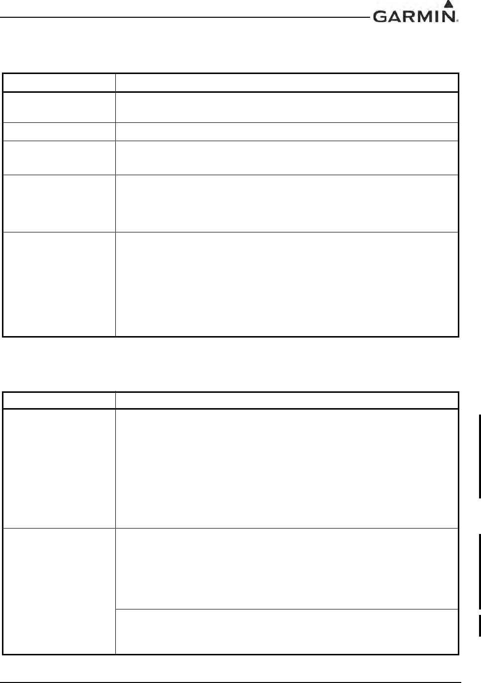
CURRENT REVISION DESCRIPTION
DOCUMENT PAGINATION
Revision Page
Number(s) Section
Number Description of Change
W
1-3 1.4.2 Specified unit and connector weights
1-6 1.4.6 Specified squelch specifications
1-9 1.4.10 Specified power requirements
1-10 1.4.11 Added -40 unit, edited RTCA reference, and added note
1-11 1.5 Specified emission type for each unit
1-12 1.6 Replaced “WAAS” with “LNAV/VNAV, LP, and LPV” and added
software specific paragraph
1-34 - 1-39 1.6.8 & 1.6.9 Added -40 TSOs and TSO deviations
1-41 - 1-43 1.6.10.2 Added TSOs and edited AC references
1-46 1.6.12 Specified regulatory specs by unit
1-47 1.7 Added GDR 66 Installation Manual reference
2-1 2.1.1 Added -40 unit
2-2 2.1.2 Added IF Seal kit
2-3 2.1.3 Added TSOs and specified units
2-3 2.1.3.2 Clarified software version and corrected section
reference
2-6 2.2.1 Standardized antenna wording
2-9 2.2.3 Clarified Com antenna location wording
2-13 2.7 Added TSO
2-14 2.8.1 Added Mounting Limitations section
3-6 3.8 Edited RTCA reference and added -40 unit
4-1 - 4-5 4Added -40 pins
4-24 4.6.1 Specified functions based on unit and software
4-25 - 4-27 4.6.2.3 - 4.6.2.5 Clarified spec descriptions and added -40 pins
4-28 - 4-30 4.7.1 - 4.7.2.7 Added -40 pins
Section Page Range
Table of Contents i – viii
Section 1 1-1 – 1-48
Section 2 2-1 – 2-18
Section 3 3-1 – 3-8
Section 4 4-1 – 4-40
Section 5 5-1 – 5-6
Appendix A A-1 – A-4
Appendix B B-1 – B-6
Appendix C C-1 – C-7
DRAFT

GIA 63 Installation Manual 190-00303-05
Page ii Rev. W
INFORMATION SUBJECT TO EXPORT CONTROL LAWS
This document may contain information which is subject to the Export Administration
Regulations (“EAR”) issued by the United States Department of Commerce (15 CFR,
Chapter VII Subchapter C) and which may not be exported, released or disclosed to
foreign nationals inside or outside the United States without first obtaining an export
license. The preceding statement is required to be included on any and all reproductions
in whole or in part of this manual.
DRAFT

190-00303-05 GIA 63 Installation Manual
Rev. W Page iii
Limited Warranty
All Garmin avionics products are warranted to be free from defects in materials or workmanship for: two years from the date of
purchase for new Remote-Mount and Panel-Mount products; one year from the date of purchase for new portable products and any
purchased newly-overhauled products; six months for newly-overhauled products exchanged through a Garmin Authorized
Service Center; and 90 days for factory repaired or newly-overhauled products exchanged at Garmin in lieu of repair. Within the
applicable period, Garmin will, at its sole option, repair or replace any components that fail in normal use. Such repairs or
replacement will be made at no charge to the customer for parts or labor, provided that the customer shall be responsible for any
transportation cost. This warranty does not apply to: (i) cosmetic damage, such as scratches, nicks and dents; (ii) consumable parts,
such as batteries, unless product damage has occurred due to a defect in materials or workmanship; (iii) damage caused by
accident, abuse, misuse, water, flood, fire, or other acts of nature or external causes; (iv) damage caused by service performed by
anyone who is not an authorized service provider of Garmin; or (v) damage to a product that has been modified or altered without
the written permission of Garmin. In addition, Garmin reserves the right to refuse warranty claims against products or services that
are obtained and/or used in contravention of the laws of any country.
THE WARRANTIES AND REMEDIES CONTAINED HEREIN ARE EXCLUSIVE AND IN LIEU OF ALL OTHER
WARRANTIES, WHETHER EXPRESS, IMPLIED OR STATUTORY, INCLUDING ANY LIABILITY ARISING UNDER
ANY WARRANTY OF MERCHANTABILITY OR FITNESS FOR A PARTICULAR PURPOSE, STATUTORY OR
OTHERWISE. THIS WARRANTY GIVES YOU SPECIFIC LEGAL RIGHTS, WHICH MAY VARY FROM STATE TO
STATE.
IN NO EVENT SHALL GARMIN BE LIABLE FOR ANY INCIDENTAL, SPECIAL, INDIRECT OR CONSEQUENTIAL
DAMAGES, WHETHER RESULTING FROM THE USE, MISUSE OR INABILITY TO USE THE PRODUCT OR FROM
DEFECTS IN THE PRODUCT. SOME STATES DO NOT ALLOW THE EXCLUSION OF INCIDENTAL OR
CONSEQUENTIAL DAMAGES, SO THE ABOVE LIMITATIONS MAY NOT APPLY TO YOU.
Garmin retains the exclusive right to repair or replace (with a new or newly-overhauled replacement product) the product or
software or offer a full refund of the purchase price at its sole discretion. SUCH REMEDY SHALL BE YOUR SOLE AND
EXCLUSIVE REMEDY FOR ANY BREACH OF WARRANTY.
Online Auction Purchases: Products purchased through online auctions are not eligible for warranty coverage. Online auction
confirmations are not accepted for warranty verification. To obtain warranty service, an original or copy of the sales receipt from
the original retailer is required. Garmin will not replace missing components from any package purchased through an online
auction.
International Purchases: A separate warranty may be provided by international distributors for devices purchased outside the
United States depending on the country. If applicable, this warranty is provided by the local in-country distributor and this
distributor provides local service for your device. Distributor warranties are only valid in the area of intended distribution. Devices
purchased in the United States or Canada must be returned to the Garmin service center in the United Kingdom, the United States,
Canada, or Taiwan for service.
Garmin International, Inc. Garmin (Europe) Ltd.
1200 E. 151st Street Liberty House
Olathe, KS 66062, U.S.A. Bulls Copse Road
Phone: 800/800.1020 Hounsdown Business Park
FAX: 913/397.0836 Southampton, SO40 9RB, UK
Telephone: 44 (0) 8708501241
DRAFT

GIA 63 Installation Manual 190-00303-05
Page iv Rev. W
1 GENERAL DESCRIPTION ...........................................................................1-1
1.1 Introduction ..................................................................................................................... 1-1
1.2 Equipment Description.................................................................................................... 1-1
1.3 Interface Summary .......................................................................................................... 1-2
1.4 Technical Specifications.................................................................................................. 1-3
1.5 License Requirements.................................................................................................... 1-11
1.6 Certification................................................................................................................... 1-12
1.7 Reference Documents.................................................................................................... 1-47
2 INSTALLATION OVERVIEW......................................................................2-1
2.1 Introduction ..................................................................................................................... 2-1
2.2 Installation Considerations .............................................................................................. 2-6
2.3 Rack Considerations...................................................................................................... 2-10
2.4 Cabling and Wiring ....................................................................................................... 2-11
2.5 Cooling Air.................................................................................................................... 2-11
2.6 GIA 63 Minimum Installation Requirements................................................................ 2-12
2.7 GIA 63W and GIA 63H Minimum Installation Requirements ..................................... 2-13
2.8 Mounting Requirements ................................................................................................ 2-14
3 INSTALLATION PROCEDURE...................................................................3-1
3.1 Unpacking Unit................................................................................................................ 3-1
3.2 Wiring Harness Installation............................................................................................. 3-2
3.3 Antenna Installation......................................................................................................... 3-3
3.4 Cable Installation............................................................................................................. 3-3
3.5 Backshell Assembly ........................................................................................................ 3-4
3.6 Unit Installation ............................................................................................................... 3-4
3.7 Post Installation Configuration & Checkout ................................................................... 3-5
3.8 Continued Airworthiness................................................................................................. 3-6
4 SYSTEM INTERCONNECTS........................................................................4-1
4.1 Pin Function List ............................................................................................................. 4-1
4.2 Power and Antennas ...................................................................................................... 4-17
4.3 GIA System ID Program ............................................................................................... 4-19
4.4 Serial Data ..................................................................................................................... 4-19
4.5 Discrete I/O.................................................................................................................... 4-23
4.6 COM/VOR/ILS/Digital Audio ...................................................................................... 4-24
4.7 VOR/ILS Indicator ........................................................................................................ 4-28
4.8 RMI/OBI........................................................................................................................ 4-32
4.9 DME Tuning and ADF.................................................................................................. 4-33
4.10 Auto Pilot..................................................................................................................... 4-35
DRAFT

190-00303-05 GIA 63 Installation Manual
Rev. W Page v
Appendix A GIA 63 MAIN BOOT BLOCK UPLOADING INSTRUCTIONS .....A-1
A.1 Introduction.................................................................................................................... A-1
A.2 Determining Current Boot Block................................................................................... A-1
A.3 Loading Boot Block Version 4.01................................................................................. A-2
A.4 Loading GIA Main Software (only if GIA main software was cancelled in Section A.2)A-3
Appendix B OUTLINE AND INSTALLATION DRAWINGS................................B-1
Appendix C INTERCONNECT DRAWINGS...........................................................C-1
DRAFT
GIA 63 Installation Manual 190-00303-05
Page vi Rev. W
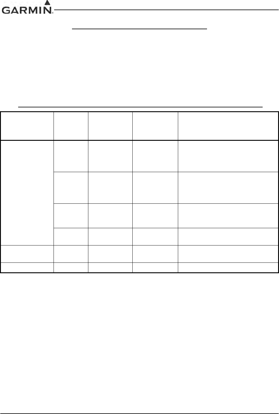
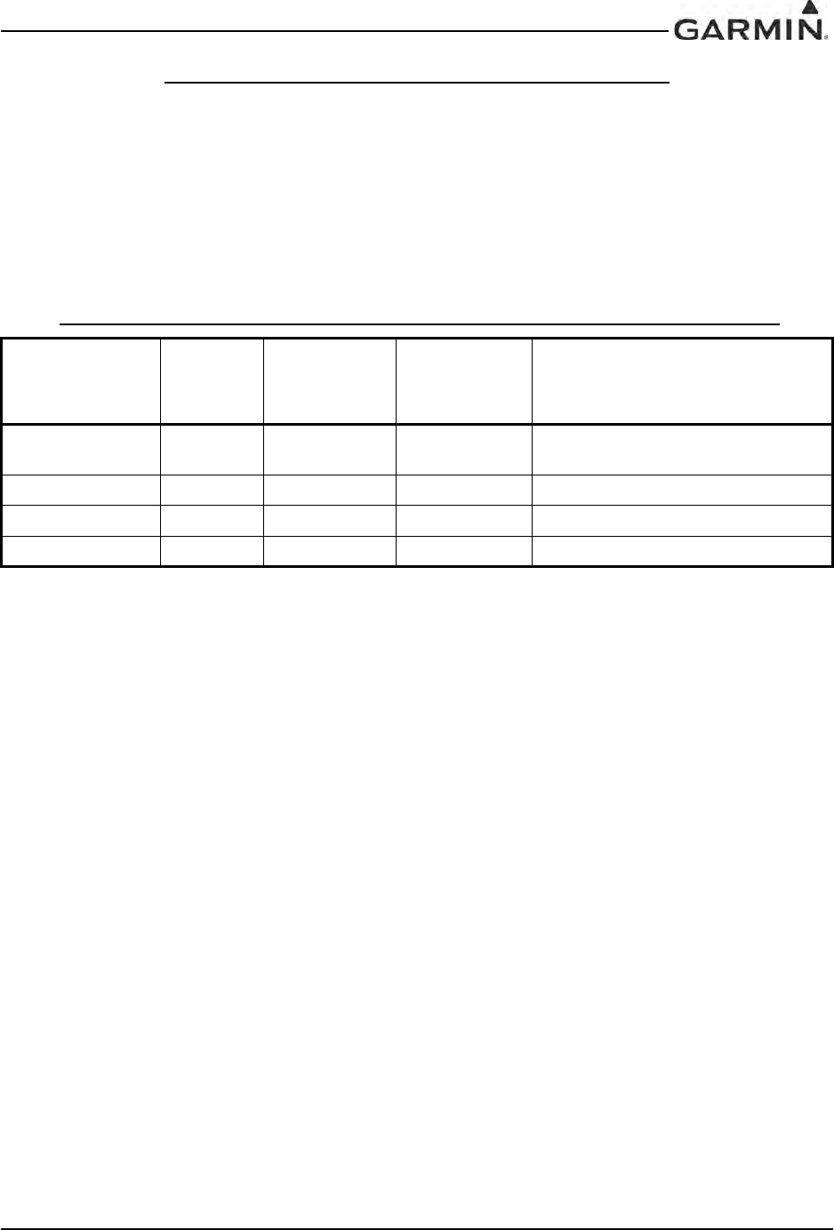
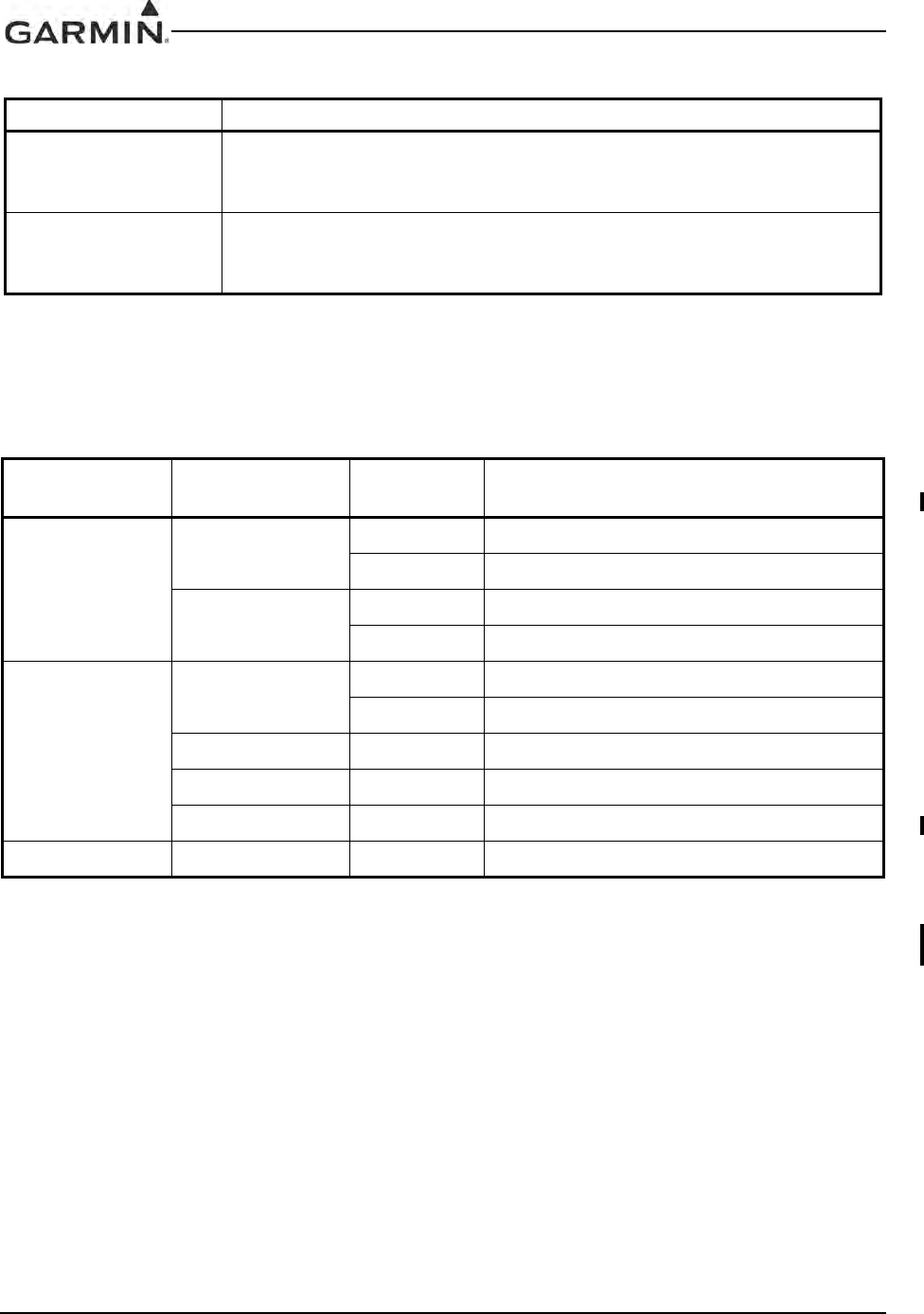
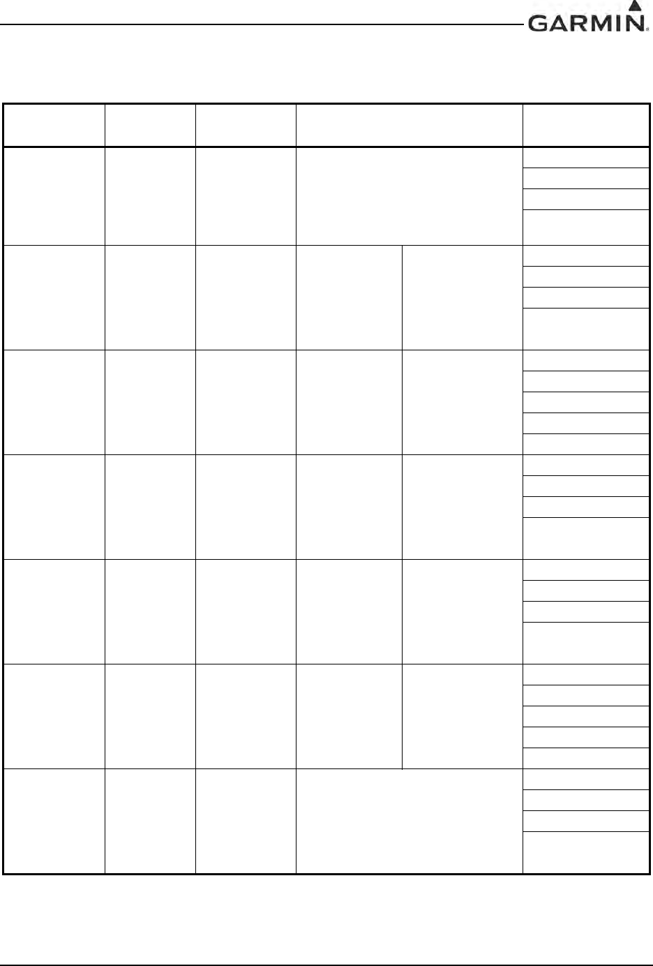
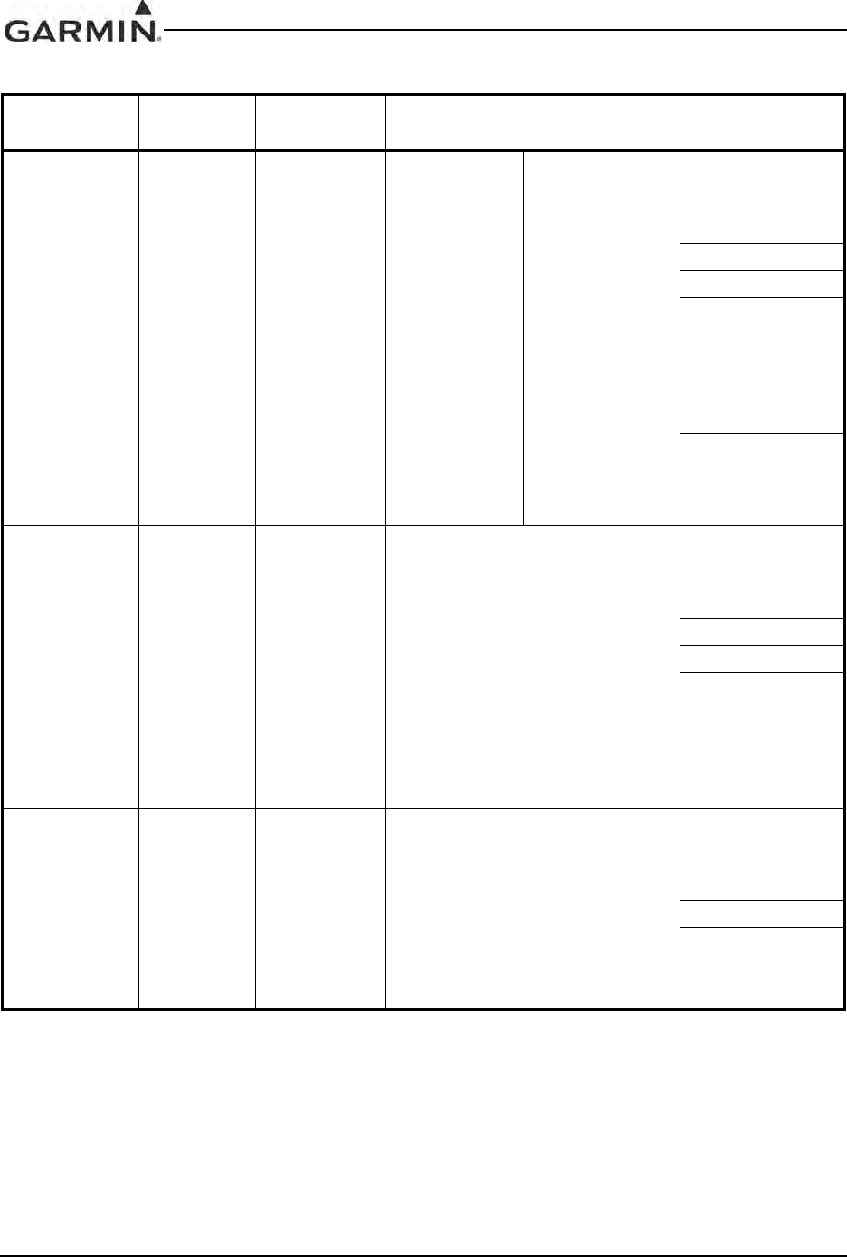
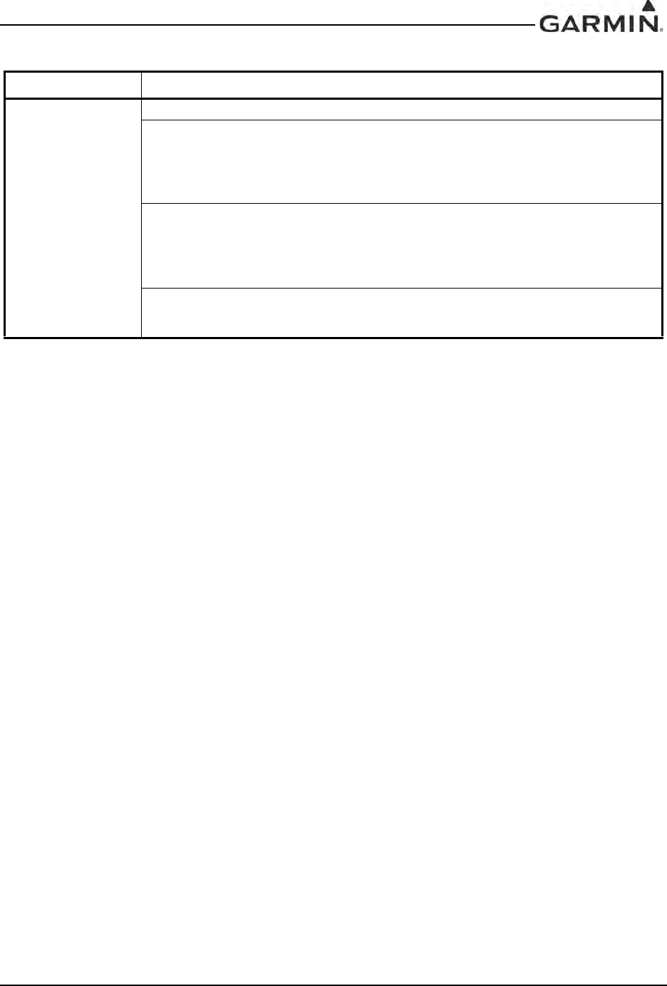
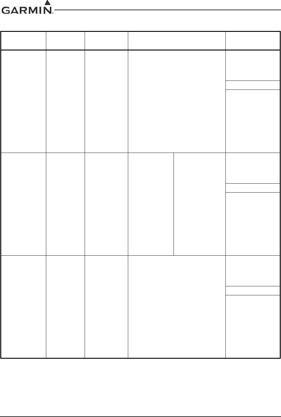
GIA 63 HARDWARE MOD LEVEL HISTORY
The following table identifies hardware modification (Mod) Levels for the GIA 63. Mod Levels are listed
with the associated service bulletin number, service bulletin date, and the purpose of the modification.
The table is current at the time of publication of this manual (see date on front cover) and is subject to
change without notice. Authorized Garmin Sales and Service Centers are encouraged to access the most
up-to-date bulletin and advisory information on the Garmin Dealer Resource web site at
www.garmin.com using their Garmin-provided user name and password.
GIA 63 P/N 011-00781-00, 011-00781-01 HARDWARE MOD LEVEL HISTORY
APPLICABLE
LRU PART
NUMBER
MOD
LEVEL
SERVICE
BULLETIN
NUMBER
SERVICE
BULLETIN
DATE
PURPOSE OF
MODIFICATION
011-00781-00
1 0416 9/13/2004
This modification consists of
modifying the voice alert audio
output circuit, enabling it to power
down when not in use.
2 0418 9/8/2004
This Service Bulletin consists of
visually inspecting the GIA 63 Main2
board for incorrectly installed
capacitors.
3 0505 1/19/2005 This modification addresses a
potential GIA 63 COM transceiver
interference condition.
4N/A N/A
More robust capacitors installed in
the power supply backup circuit.
011-00781-01 1 N/A N/A More robust capacitors installed in
the power supply backup circuit.
DRAFT
190-00303-05 GIA 63 Installation Manual
Rev. W Page vii
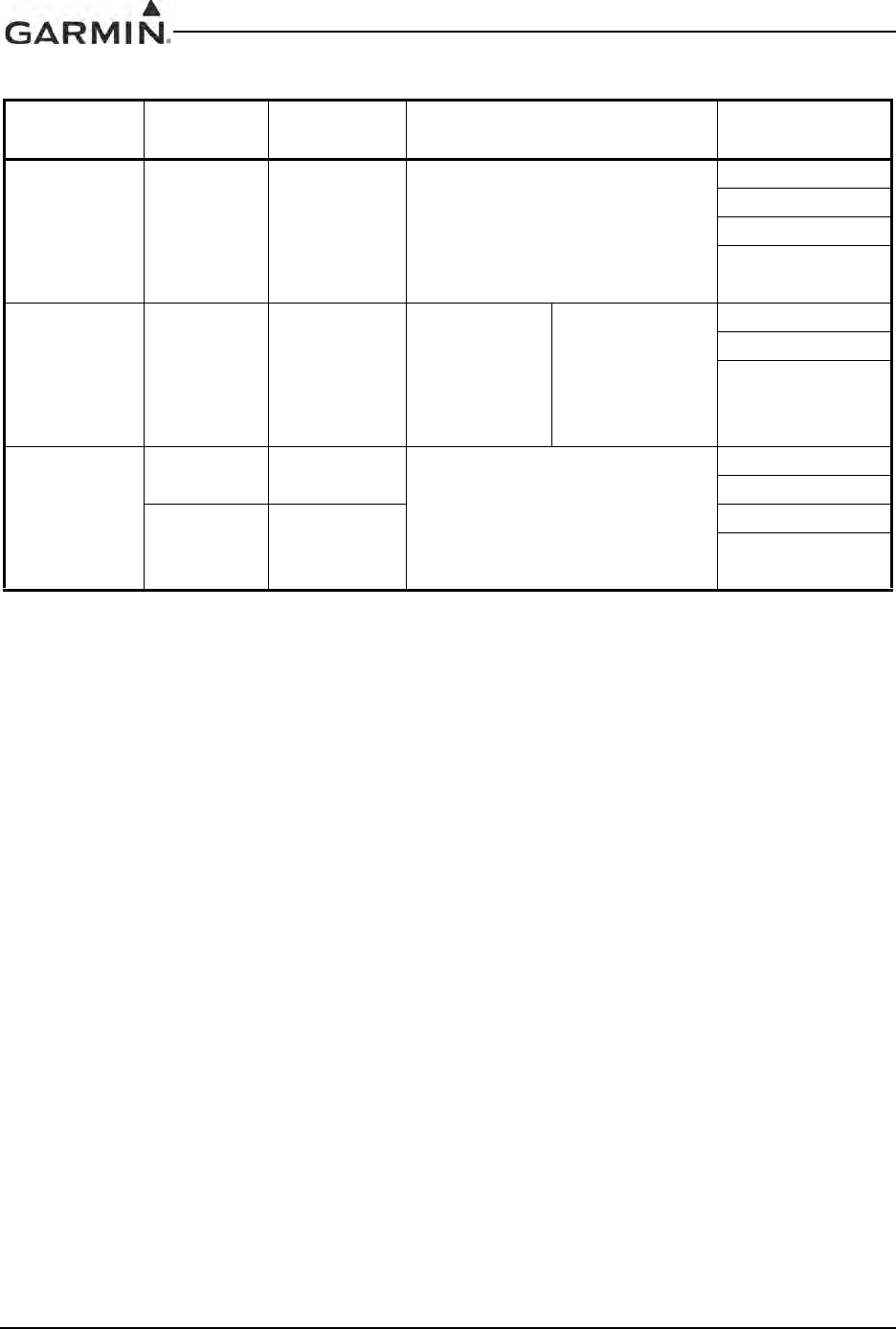
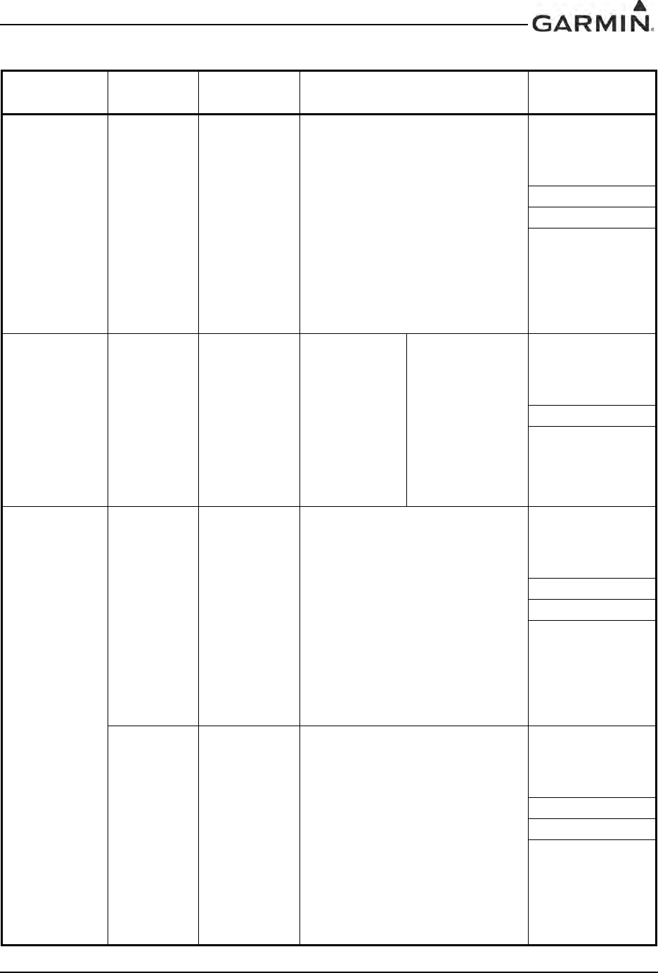
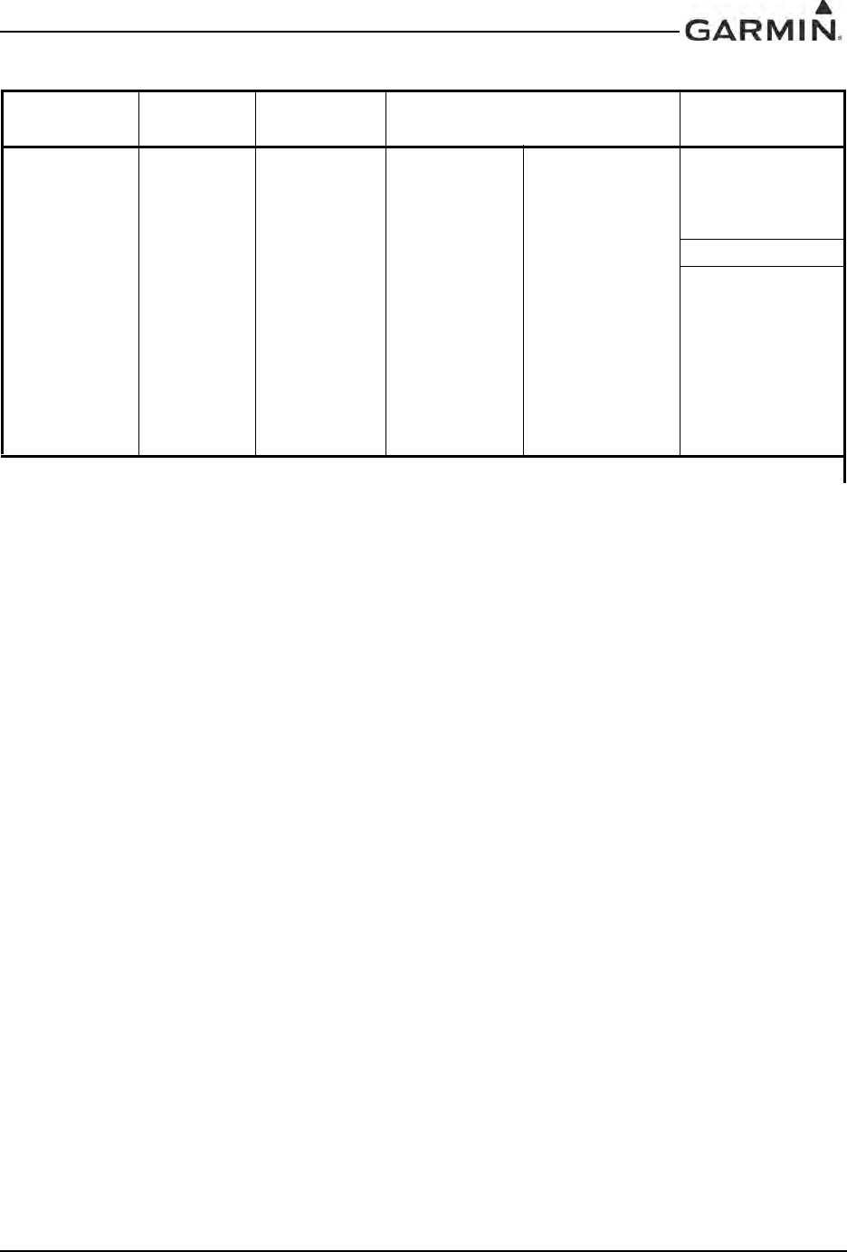
GIA 63W/GIA 63H HARDWARE MOD LEVEL HISTORY
The following table identifies hardware modification (Mod) Levels for the GIA 63W and GIA 63H. Mod
Levels are listed with the associated service bulletin number, service bulletin date, and the purpose of the
modification. The table is current at the time of publication of this manual (see date on front cover) and is
subject to change without notice. Authorized Garmin Sales and Service Centers are encouraged to access
the most up-to-date bulletin and advisory information on the Garmin Dealer Resource web site at
www.garmin.com using their Garmin-provided user name and password.
GIA 63W/GIA 63H P/N 011-01105-XX HARDWARE MOD LEVEL HISTORY
APPLICABLE
LRU PART
NUMBER
MOD
LEVEL
SERVICE
BULLETIN
NUMBER
SERVICE
BULLETIN
DATE
PURPOSE OF
MODIFICATION
011-01105-00 1 N/A N/A More robust capacitors installed in
the power supply backup circuit.
011-01105-01 N/A N/A N/A N/A
011-01105-20 N/A N/A N/A N/A
011-01105-30 N/A N/A N/A N/A
DRAFT

GIA 63 Installation Manual 190-00303-05
Page viii Rev. W
This page intentionally left blank
DRAFT

190-00303-05 GIA 63 Installation Manual
Rev. W Page 1-1
1 GENERAL DESCRIPTION
1.1 Introduction
This manual is intended to provide mechanical and electrical information for use in the planning and
design of an installation of the GIA 63(X) into an aircraft. This manual is not a substitute for an approved
airframe-specific maintenance manual, installation design drawing, or complete installation data package.
Attempting to install equipment by reference to this manual alone and without first planning or designing
an installation specific to your aircraft may compromise your safety and is not recommended. The content
of this manual assumes use by competent and qualified avionics engineering personnel and/or avionics
installation specialists using standard aviation maintenance practices in accordance with Title 14 of the
Code of Federal Regulations and other relevant accepted practices. This manual is not intended for use by
individuals who do not possess the competencies and abilities set forth above.
NOTE
Garmin recommends installation of the GIA 63(X) by a Garmin-authorized installer. To
the extent allowable by law, Garmin will not be liable for damages resulting from
improper or negligent installation of the GIA 63(X). For questions, please contact Garmin
Aviation Product Support at 1-888-606-5482.
1.2 Equipment Description
The GIA 63(X) is a microprocessor-based input/output Line Replaceable Unit (LRU) used in a Garmin
Integrated Flight Deck. The GIA 63(X) communicates with the GDU via Ethernet high-speed data bus
(HSDB), and with other LRUs using RS-232, RS-485/422, and ARINC 429. All configuration is done
through the GDU. The GIA 63(X) contains the following sub-assemblies:
• A main processor that interfaces with all LRUs in the G1000 sub-system and performs calculations
for the GFC 700 autopilot (if equipped).
• A twelve channel parallel GPS receiver that simultaneously tracks and uses up to 12 satellites. The
GIA 63W and GIA 63H include a 15 channel WAAS certified GPS receiver.
• A VHF COM transceiver that provides tuning from 118.00 to 136.992 MHz in 25 kHz or 8.33 kHz
spacing for 760 or 2280 channel configuration respectively.
• A VOR/ILS localizer receiver that provides tuning from 108.00 to 117.95 MHz in 50 kHz
increments.
• An ILS glideslope receiver that provides tuning from 328.6 to 335.4 MHz as paired with the
frequency tuned on the VOR/ILS localizer receiver.
CAUTION
The operation of unapproved cellular telephones or other unapproved cellular devices aboard
aircraft while airborne is prohibited by FCC rules. Due to the potential for interference with
onboard systems, the operation of unapproved cellular communication devices while onboard an
aircraft that is on the ground is subject to FAA regulations 14 CFR 91.21.
FCC regulation 47 CFR 22.925 prohibits airborne operation of unapproved cellular telephones
installed in or carried aboard aircraft. Unapproved cellular telephones must not be operated
aboard any aircraft while the aircraft is off the ground. When any aircraft leaves the ground, all
unapproved cellular telephones on board that aircraft must be turned off.
Unapproved cellular telephones that are on, even in a monitoring state, can disrupt GPS
performance.
DRAFT

GIA 63 Installation Manual 190-00303-05
Page 1-2 Rev. W
1.3 Interface Summary
1.3.1 Primary Interfaces
The GIA 63(X) is designed as an open architecture system that provides the following interfaces:
• 1 dedicated Ethernet High-Speed Data Bus (HSDB) input/output channel
• 2 Controller Area Network (CAN) I/O channels
• 8 Main ARINC 429 inputs
• 3 Main ARINC 429 outputs
• 1 VOR/ILS ARINC 429 input
• 1 VOR/ILS ARINC 429 output
• 5 RS-485 input/output channels (any two RS-485 channels can be configured to form a single
RS-422 channel)
• 8 RS-232 input/output channels
• 41 Discrete inputs
• 14 Discrete outputs
• 24 Annunciator outputs
1.3.2 Additional Interfaces
The GIA 63(X) can provide interfaces for the following additional equipment:
• Autopilot
• Altitude encoder/serializer
• Fuel management systems
• Lightning detection systems
• Traffic awareness systems
• Data link systems
• External annunciators
• DME (including King Serial)
• ADF
DRAFT
190-00303-05 GIA 63 Installation Manual
Rev. W Page 1-3
1.4 Technical Specifications
1.4.1 Environmental Qualification Form
It is the responsibility of the installing agency to obtain the latest revision of the GIA 63(X) Environmental
Qualification Form. This form is available directly from Garmin under the following part number:
GIA 63 Environmental Qualification Form, Garmin part number 005-00148-02
GIA 63W Environmental Qualification Form, Garmin part number 005-00235-00
The GIA 63H and the GIA 63W are included in the 005-00235-00. To obtain a copy of this form, see the
dealer/OEM portion of the Garmin web site (www.garmin.com).
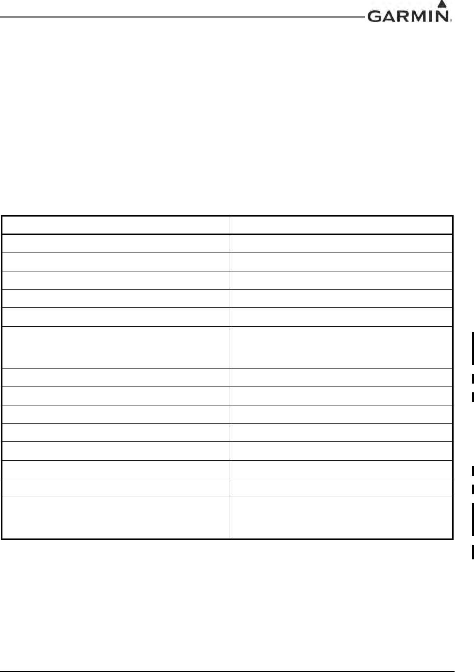
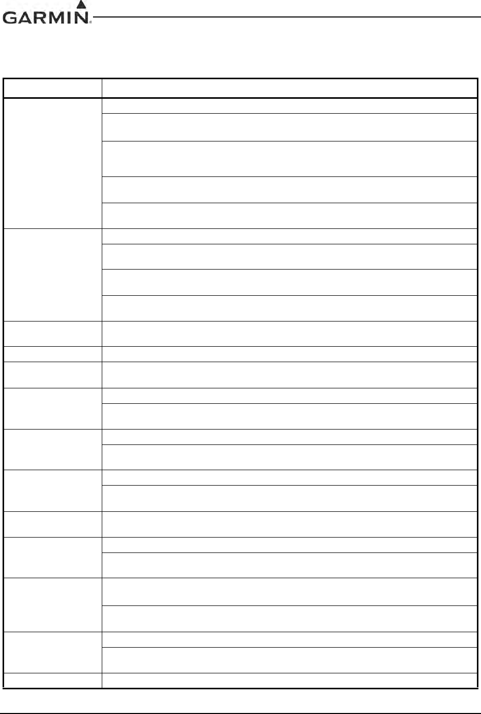
1.4.2 Physical Characteristics
Table 1-1. GIA 63(X) Physical Characteristics
Characteristic Specification
Modular Rack Width 3.83 inches (97.3 mm)
Modular Rack Height 7.26 inches (184.4 mm)
Standalone Rack Width 3.88 inches (98.5 mm)
Standalone Rack Height 6.91 inches (175.5 mm)
Depth w/connectors (Modular and Standalone) 10.20 inches (259.1 mm)
Unit Weight 011-00781-0X: 5.3 lbs. (2.40 kg)
011-01105-0X/-1X/-2X: 5.3 lbs. (2.40 kg)
011-01105-4X: 5.5 lbs. (2.49 kg)
Modular Rack Weight w/Back Plate 1.0 lbs. (0.45 kg)
Standalone Rack Weight w/Back Plate 1.3 lbs. (0.59 kg)
Helicopter Rack Width 3.76 inches (95.4 mm)
Helicopter Rack Height 7.00 inches (177.8 mm)
Depth w/connectors (Helicopter) 10.18 inches (258.6 mm)
Unit Weight (Helicopter) 011-01105-3X: 5.4 lbs (2.45 kg)
Helicopter Rack Weight w/Back Plate 1.6 lbs (0.74 kg)
Connector Kit Weight* 011-01000-00: 1.3 lbs (0.59 kg)
011-01000-01: 1.1 lbs (0.50 kg)
011-01000-03: 1.1 lbs (0.50 kg)
* Only the GIA 63H unit (011-01105-3X) together with the Helicopter Rack (011-02425-00), Back Plate (011-00963-01), and Connector Kit
(011-01000-01) is approved for DO-160F, Category U, Curve G vibration levels.
DRAFT

GIA 63 Installation Manual 190-00303-05
Page 1-4 Rev. W
1.4.3 General Specifications
For detailed specifications, see the Environmental Qualification Form.
Table 1-2. GIA 63(X) General Specifications
Characteristic Specification
Operating Temperature Range -40°C to +65°C. For more details see Environmental
Qualification Form
Humidity 95% non-condensing
Altitude Range -1,500 ft to 50,000 ft
DRAFT
190-00303-05 GIA 63 Installation Manual
Rev. W Page 1-5
1.4.4 GPS Specification (GIA 63 only)
1.4.5 WAAS Specific GPS Specifications (GIA 63W & GIA 63H)
Table 1-3. GIA 63 GPS Specifications
Characteristic Specification
Acquisition Times
a) Search-the-Sky (without almanac, without initial position or
time): 5 minutes
b) AutoLocate™ (with almanac, without initial position or
time): 5 minutes
c) Cold Start (position known to 300 nm, time known to 10 minutes,
with valid almanac): 45 seconds
d) Warm Start (position known to 10 nm, time known to 10 minutes,
with valid almanac and ephemeris): 15 seconds
Max Velocity 1000 knots
Dynamics 6g
Antenna power supply 20 mA typical, 40 mA max at 4.6 VDC
Table 1-4. GIA 63W and GIA 63H GPS Specifications
Characteristic Specification
Number of channels 15 (12 GPS and 3 GPS/WAAS/SBAS)
Frequency 1575.42 MHz L1, C/A code
Sensitivity
(acquisition)
-116 dBm to -134.5 dBm GPS
-116 dBm to -134.5 dBm WAAS
Sensitivity
(drop lock) -144 dBm
Lat/Long position
accuracy <1.25 meter RMS horizontal, <2 meter vertical, with WAAS
Velocity 1000 knots maximum (above 60,000 ft)
TTFF (time to first fix) 1:45 min. typical with current almanac, position, and tim
Reacquisition 10 seconds typical for signal outages of 30 seconds or less
Position update
interval 0.2 sec (5 Hz)
1 pps (pulse per
second) ±275 nsec of UTC second during steady-state navigation
Datum WGS-84
SATCOM
compatibility
Compatible on aircraft equipped with SATCOM (see Section
2.1.3.2 for SATCOM compatible antennas)
Antenna power supply
at GPS port 4.3 VDC to 4.8 VDC @ 60 mA
DRAFT
GIA 63 Installation Manual 190-00303-05
Page 1-6 Rev. W
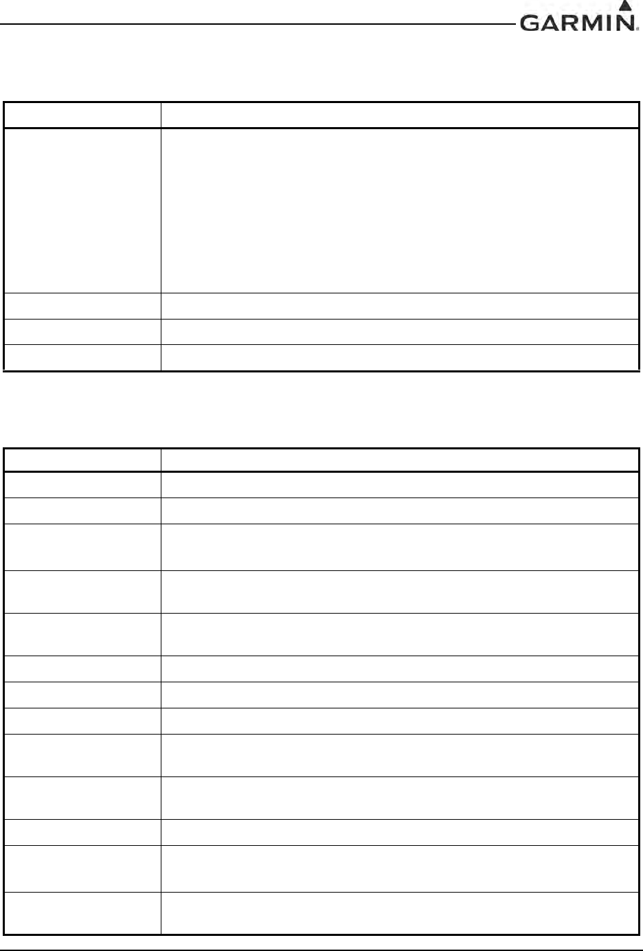
1.4.6 COM Transceiver Specifications
Table 1-5. GIA 63(X) COM Transceiver Specifications
Characteristic Specification
Audio Output 100 mW minimum into a 500 Ω load
Audio Response Less than 6 dB of variation between 350 and 2500 Hz
Audio Distortion The distortion in the receiver audio output shall not exceed 25% at all levels
up to 100 mW
AGC Characteristics The audio output shall not vary by more than 6 dB when the level of the RF
input signal, modulated 30% at 1000 Hz, is varied from 5 μV to 100,000 μV
(hard)
Sensitivity (S+N)/N on all channels shall be greater than 6 dB when the RF level is 2 μV
(hard) modulated 30% at 1000 Hz at rated audio
25 kHz Channel
Squelch
2 μv (hard) ±6 dB
8.33 kHz Channel
Squelch
011-00781-0X and 011-01105-0X:
3 μv (hard) ±6 dB
011-01105-2X/-3X/-4X:
2 μv (hard) ±6 dB
Selectivity
6 dB BW is greater than ±8 kHz for 25 kHz channeling
60 dB BW is less than ±25 kHz for 25 kHz channeling
6 dB BW is greater than ±2.778 kHz for 8.33 kHz channeling
60 dB BW is less than ±7.37 kHz for 8.33 kHz channeling
Spurious Response Greater than 80 dB
Transmitter Power
At Least 16 watts when Vin = 28 VDC
At least 10 watts when Vin = 14 VDC (011-01105-2X and 011-01105-3X
only)
Transmitter Duty Cycle Recommended 10% maximum
Modulation Capability* The modulation shall not be less than 70% and not greater than 99.9% with
a standard modulator signal applied to the transmitter
Carrier Noise Level Shall be at least 45 dB (S+N)/N
Frequency Stability 0.0005%
Demodulated Audio
Distortion Less than 10% distortion when the transmitter is modulated at least 70%
Sidetone 1.4 VRMS into a 500 Ω load when the transmitter is modulated at least 70%
Demodulated Audio
Response Shall be less than 6 dB when the audio input frequency is varied from 350 to
2500 Hz
*When utilizing the configurable microphone gain adjustments, the modulation capability specification can be met with a 70 mVrms to 3.0 Vrms
analog microphone input signal applied to the transmitter. When a digital audio microphone signal is provided by a compatible Garmin audio panel,
the modulation capability specification can be met with a minimum 70 mVrms microphone input signal applied to the audio panel.
DRAFT

190-00303-05 GIA 63 Installation Manual
Rev. W Page 1-7
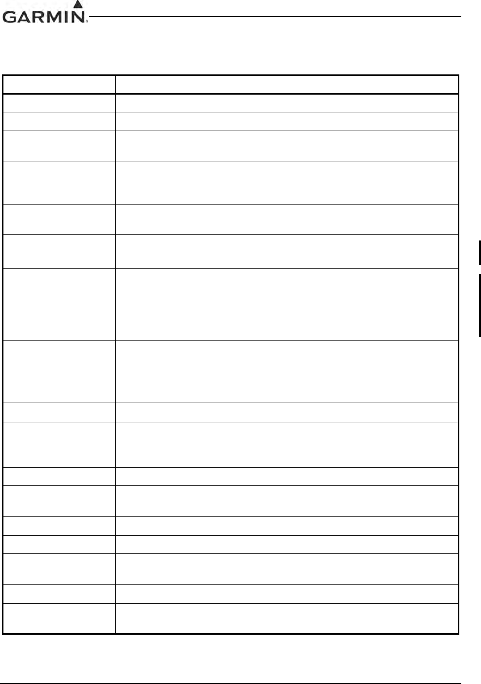
1.4.7 VOR Specifications
Table 1-6. GIA 63(X) VOR Specifications
Characteristic Specification
Receiver Audio
Sensitivity At -103.5 dBm (S+N)/N shall not be less than 6 dB
Course Deviation
Sensitivity
At –103.5 dBm deviation output shall not be less than 60% of standard
deflection (90 mV) when a VOR deviation test signal is applied (10 degrees
course difference)
Flag
The VLOC Course Deviation Flag must be flagged:
a) in the absence of an RF signal
b) in the absence of the 9960 Hz modulation
c) in the absence of either one of the two 30 Hz modulations
d) When the level of a standard VOR deviation test signal produces less
than a 50% of standard deflection
AGC Characteristics From -99 dBm to -13 dBm input of a Standard VOR Audio Test Signal, audio
output levels shall not vary more than 3 dB
Spurious Response Greater than 60 dB
VOR OBS Bearing
Accuracy The bearing information as presented to the pilot shall not have an error in
excess of 2.7° as specified by RTCA DO-196 and EuroCAE ED-22B
Audio Output A minimum 100 mW into a 500 Ω load
Audio Response Less than 6 dB of variation between 350 and 2500 Hz. In voice mode, an
ident tone of 1020 Hz shall be attenuated at least 20 dB
Audio Distortion The distortion in the receiver audio output shall not exceed 10% at all levels
up to 100 mW
Selectivity 6 dB BW is greater than 16.5 kHz
DRAFT
GIA 63 Installation Manual 190-00303-05
Page 1-8 Rev. W
1.4.8 LOC Specifications
Table 1-7. GIA 63(X) LOC Specifications
Characteristic Specification
Receiver Audio
Sensitivity At -103.5 dBm (S+N)/N shall not be less than 6 dB
Course Deviation
Sensitivity At –103.5 dBm, deviation output shall not be less than 60% of standard
deflection when a LOC deviation test signal is applied
Flag
The VLOC Course Deviation Flag must be flagged:
a) When the level of a standard deviation test signal produces 50% or less of
standard deflection of the deviation indicator
b) In the absence of 150 Hz modulation
c) In the absence of 90 Hz modulation
d) In the absence of both 90 Hz and 150 Hz modulation
e) In the absence of RF
AGC Characteristics From –99 dBm and –13 dBm input of a Standard VOR Audio Test Signal,
audio output levels shall not vary more than 3 dB
Selectivity 6 dB BW is greater than 9 kHz
69 dB BW is less than 36 kHz
Standard Deflection
a) With a standard deflection ‘FLY LEFT’ condition (90 Hz dominant), the
output shall be +90 mV ± 9 mV
b) With a standard deflection ‘FLY RIGHT’ condition (150 Hz dominant), the
output shall be -90 mV ± 9 mV
Spurious Response Greater than 60 dB
Centering Accuracy Typical 0 ± 3 mV (Max error 9.9 mV per RTCA DO-195)
Audio Output A minimum 100 mW into a 500 Ω load
Audio Response Less than 6 dB of Variation between 350 and 2500 Hz. In voice mode, an
ident tone of 1020 Hz shall be attenuated at least 20 dB
Audio Distortion The distortion in the receiver audio output shall not exceed 10% at all levels
up to 100 mW
DRAFT
190-00303-05 GIA 63 Installation Manual
Rev. W Page 1-9
1.4.9 Glideslope Specifications
1.4.10 Power Requirements
Table 1-8. GIA 63(X) Glideslope Specifications
Characteristic Specification
Sensitivity At –93 dBm, deviation output shall not be less than 60% of standard
deflection when glideslope deviation test signal is applied
Centering Accuracy 0 ± .0091 ddm or 0 ± 7.8 mV
Selectivity 6 dB BW is greater than 17 kHz
69 dB BW is less than 132 kHz
Standard deflection
a) With a standard deflection ‘FLY DOWN’ condition (90 Hz dominant), the
output shall be -78 mV ± 7.8 mV
b) With a standard deflection ‘FLY UP’ condition (150 Hz dominant), the
output shall be +78 mV ± 7.8 mV
Flag
The GS Course Deviation Flag must be flagged:
a) When the level of a standard deviation test signal produces 50% or less of
standard deflection of the deviation indicator
b) In the absence of 150 Hz modulation
c) In the absence of 90 Hz modulation
d) In the absence of both 90 Hz and 150 Hz modulation
e) In the absence of RF
Table 1-9. GIA 63(X) Power Specifications
Characteristic Specification
Input Voltage Range
For P601:
011-00781-0X and 011-01105-0X: 28 Vdc
011-01105-2X/-3X: 14/28 Vdc
011-01105-4X: 28 Vdc
For P605:
011-00781-0X and 011-01105-0X/-1X/-2X/-3X: 14/28 Vdc
011-01105-4X: 28 Vdc
See the Environmental Qualification Form for details on surge ratings and
minimum/maximum operating voltages.
Power Requirements
for P601
(COM Connector)
011-00781-0X and 011-01105-0X/-2X/-3X:
0.3 A max @ 27.5 Vdc (not transmitting);
4.3 A max @ 27.5 Vdc (transmitting)
011-01105-4X:
0.4 A max @ 27.5 Vdc (not transmitting);
4.4 A max @ 27.5 Vdc (transmitting)
011-01105-2X/-3X only:
0.6 A max @ 13.75 Vdc (not transmitting);
6.0 A max @ 13.75 Vdc (transmitting)
DRAFT
GIA 63 Installation Manual 190-00303-05
Page 1-10 Rev. W
1.4.11 Power Interrupt
Superflag Power
Requirements for P605
(Main 2 Connector)
Power depends upon loads present on Superflag output pins
(see Sections 4.7.2.1 and 4.10.7)
Power Requirements
for P605
(Main 2 Connector)
1.0 A max @ 27.5 Vdc (Without Superflags Active)
2.0 A max @ 13.75 Vdc (Without Superflags Active)
*Only 011-01105-20 and 011-01105-30 units support both 14 Vdc and 28 Vdc COMs. All
other units only support 28 Vdc COMs.
Table 1-10. GIA 63(X) Power Interrupt
Unit Name Unit Part Number Mod Status* Long Term Power Interrupt
Category Per RTCA DO-160**
GIA 63
011-00781-00 4A (200mS)
0, 1, 2, 3 B (50mS)
011-00781-01 1A (200mS)
0B (50mS)
GIA 63W
011-01105-00 1A (200mS)
0B (50mS)
011-01105-01 0A (200mS)
011-01105-20 0A (200mS)
011-01105-40 0A (200mS)
GIA 63H 011-01105-30 0A (200mS)
*Refer to Mod Status Table in front of manual for applicable mod levels.
**Refer to Section 3.8 for Continued Airworthiness. The DO-160 revision used for qualification of each unit is
specified in the applicable environmental qualification form.
Table 1-9. GIA 63(X) Power Specifications
Characteristic Specification
DRAFT
190-00303-05 GIA 63 Installation Manual
Rev. W Page 1-11
1.5 License Requirements
The Telecommunications Act of 1996, effective February 8, 1996, provides the FCC discretion to
eliminate radio station license requirements for aircraft and ships. The GIA 63(X) installation must comply
with current transmitter licensing requirements. To find out the specific details on whether a particular
installation is exempt from licensing, please visit the FCC web site http://wireless.fcc.gov/aviation.
Transmitter Description: Aviation-band VHF transceiver with 25 and 8.33 kHz channel spacing.
Antenna Characteristics: Broad band, 50 ohm, vertically polarized.
Rated Power: 16 Watts (28 VDC Operation)
10 Watts (14 VDC Operation; 011-01105-2X and -3X only)
Emission Type: 6K00A3E (25 kHz Channel Spacing Mode)
5K6A3E (8.33 kHz Channel Spacing Mode; 011-01105-2X/-3X/-4X
only)
Frequency of Operation: 118.000 – 136.992 MHz
If an aircraft license is required, make application for a license on FCC form 404, application for Aircraft
Radio Station License. The FCC also has a fax-on-demand service to provide forms by fax. The GIA 63(X)
owner accepts all responsibility for obtaining the proper licensing before using the transmitter.
International transmitter license procedures vary by country. Contact the local spectrum agency for license
requirements.
CAUTION
The VHF transmitter in this equipment is guaranteed to meet federal communications
commission acceptance over the operating temperature range. Modifications not
expressly approved by Garmin could invalidate the license and make it unlawful to
operate the equipment.
DRAFT

GIA 63 Installation Manual 190-00303-05
Page 1-12 Rev. W
1.6 Certification
The GIA 63 GPS receiver is certified for IFR enroute, terminal, and non-precision approaches. The GIA
63W and the GIA 63H GPS receivers are certified for LNAV/VNAV, LP, and LPV approaches.
The GIA 63(X) has been qualified to RTCA/DO-160 Section 20 RF susceptibility and Section 22 lightning
requirements. Special installation considerations are required, refer to the Environmental Qualification
Form.
The GIA 63(X) meets the requirements for GPS as a Primary Means of Navigation for Oceanic/Remote
Operations per FAA Notice N8110.60.
The GIA 63(X) is eligible for B-RNAV in accordance with AMC 20-4.
Eligible for PRNAV in accordance with PRNAV requirements: JAA Administrative & Guidance Material
Section One: General Part 3: Temporary Guidance Leaflets, Leaflet No 10: Airworthiness and Operational
Approval for Precession RNAV Operations in Designated European Airspace 7.1 Required Functions.
The GIA 63(X) with main software version 7.00 or later and GPS software version 5.0 or later have been
shown to comply with AC 20-165 Appendix 2 and AC 20-138C Appendix 4 and are eligible for use as an
ADS-B Out Position Source meeting the requirements of 14 CFR 91.227 when installed in accordance
with Garmin’s installation instructions.
The conditions and tests required for TSO approval of this article are minimum performance standards. It
is the responsibility of those installing this article either on or within a specific type or class of aircraft to
determine that the aircraft installation conditions are within the TSO standards. TSO articles must have
separate approval for installation in an aircraft. The article may be installed only if performed under 14
CFR part 43 or the applicable airworthiness requirements. At the time of publication, installations of this
TSO approved article are only approved when installed in an aircraft as part of a Garmin Integrated Flight
Deck.
The quantitative safety objective for the VHF Comm radio in the GIA 63W and the GIA 63H is 1 X 10⁻⁴
per flight hour for Class I Part 23 Airplanes, and 1 X 10⁻⁵ per flight hour for all other Part 23 airplanes and
Parts 25, 27, and 29 aircraft.
DRAFT
190-00303-05 GIA 63 Installation Manual
Rev. W Page 1-13
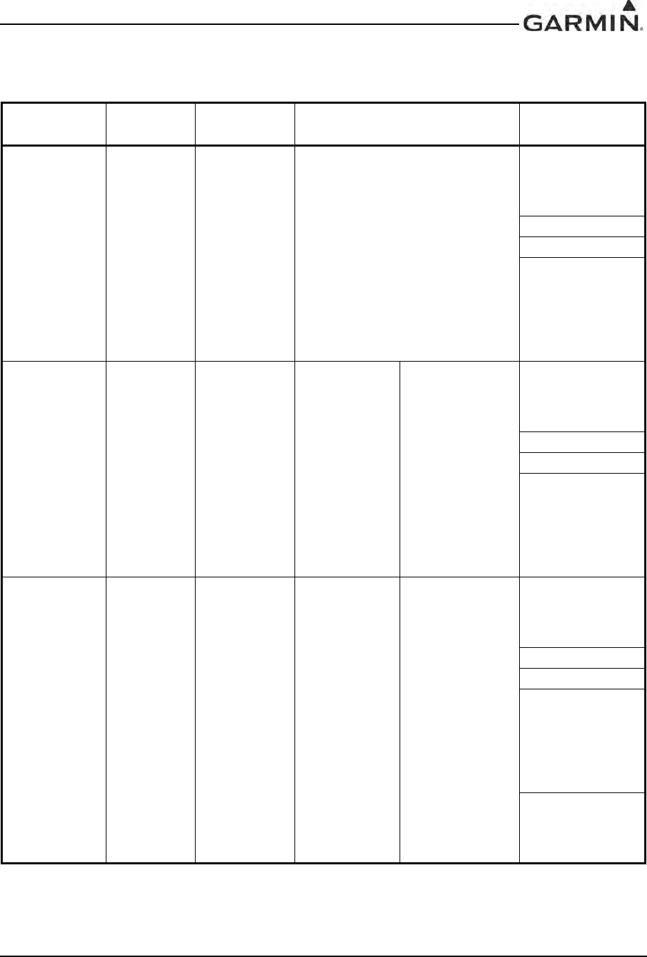
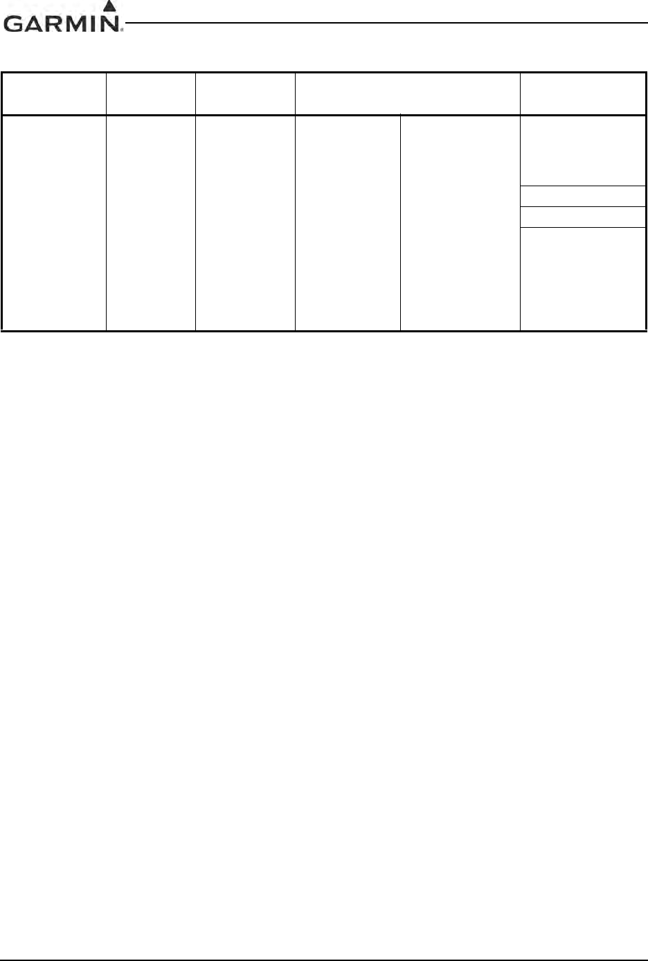
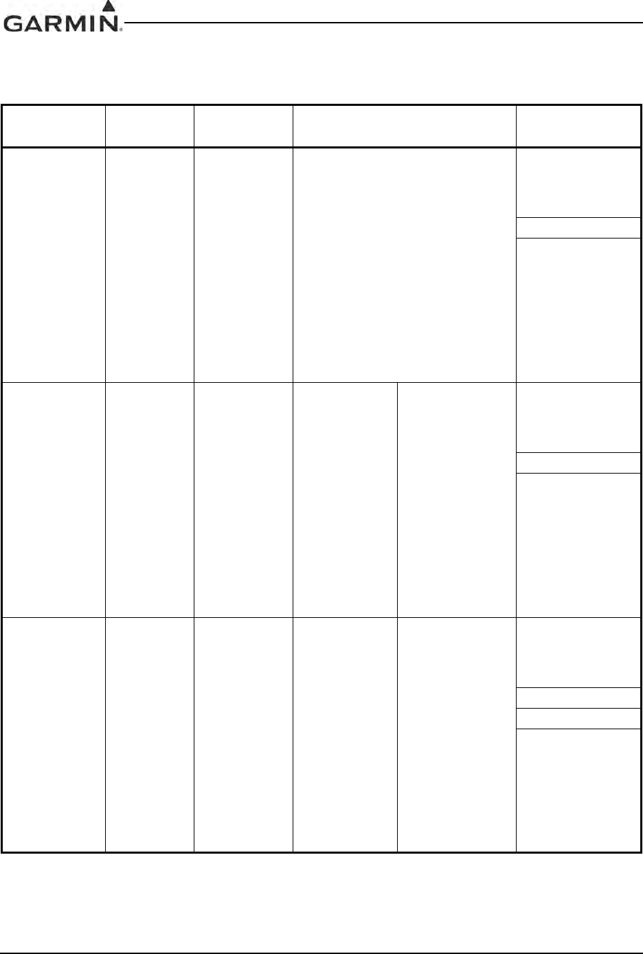
1.6.1 GIA 63 TSO/ETSO Compliance
Table 1-11. GIA 63 TSO/ETSO Compliance
Function TSO/ETSO Category Applicable LRU SW Part
Numbers Applicable CLD
Part Numbers
Automatic Pilots TSO-C9c
ETSO-C9c
All
006-B0190-()
except
006-B0190-00
through
006-B0190-19
006-C0046-()
006-C0044-()
006-C0047-()
006-C0039-01
Glideslope
Receiver
TSO-C34e
ETSO-2C34f
All
006-B0190-()
except
006-B0190-00
through
006-B0190-04
006-B0083-01
006-C0046-()
006-C0044-()
006-C0047-()
006-C0039-01
Localizer
Receiver
TSO-C36e
ETSO-2C36f Class A
All
006-B0190-()
except
006-B0190-00
through
006-B0190-04
006-B0082-02
006-C0046-()
006-C0044-()
006-C0047-()
006-C0039-01
006-C0053-00
VHF COM
Transmitter
TSO-C37d
ETSO-2C37e Class 3 and 5
All
006-B0190-()
except
006-B0190-00
through
006-B0190-04
All
006-B0081-0()
except
006-B0081-00
through
006-B0081-04
006-C0046-()
006-C0044-()
006-C0047-()
006-C0039-01
VHF COM
Receiver
TSO-C38d
ETSO-2C38e Class C and E
All
006-B0190-()
except
006-B0190-00
through
006-B0190-04
All
006-B0081-0()
except
006-B0081-00
through
006-B0081-04
006-C0046-()
006-C0044-()
006-C0047-()
006-C0039-01
VOR Receiver TSO-C40c
ETSO-2C40c
All
006-B0190-()
except
006-B0190-00
through
006-B0190-04
006-B0082-02
006-C0046-()
006-C0044-()
006-C0047-()
006-C0039-01
006-C0053-00
Flight Director
Equipment
TSO-C52b
ETSO-C52b
All
006-B0190-()
except
006-B0190-00
through
006-B0190-19
006-C0046-()
006-C0044-()
006-C0047-()
006-C0039-01
DRAFT
GIA 63 Installation Manual 190-00303-05
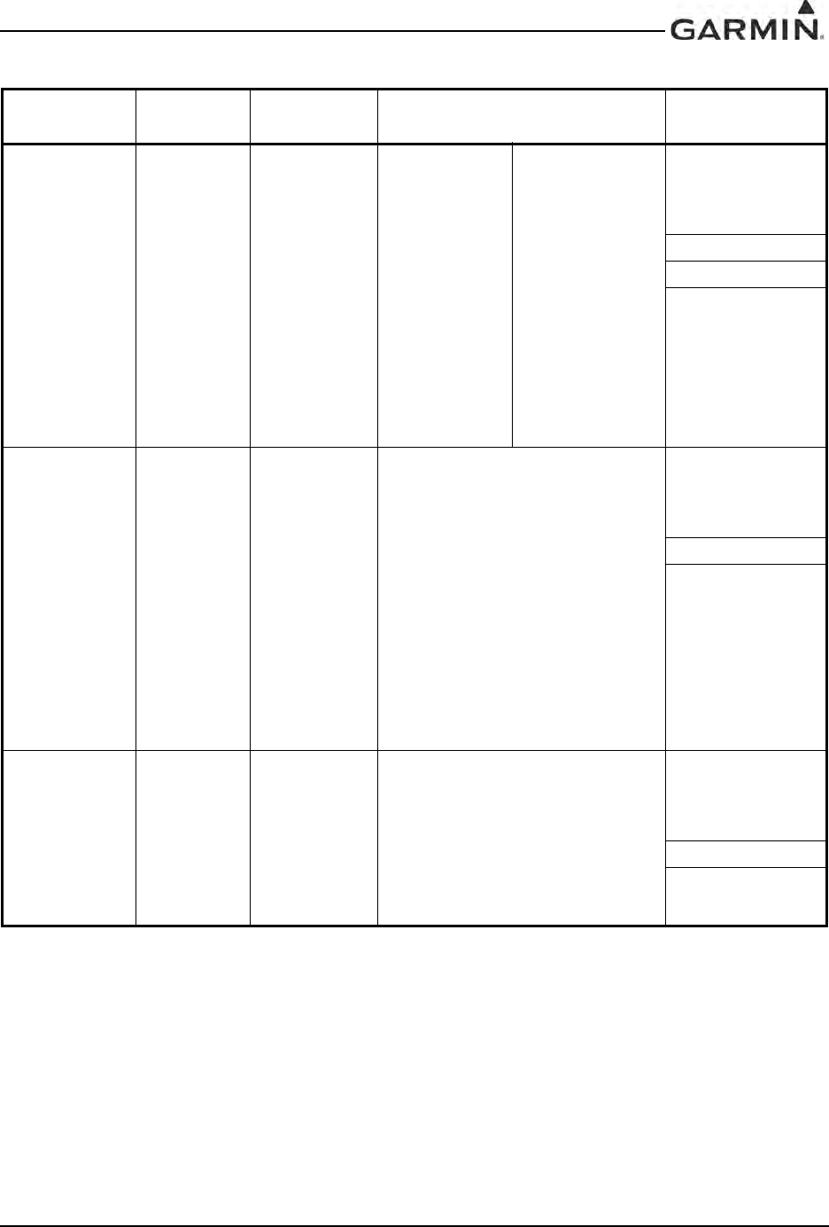
Page 1-14 Rev. W
Ground
Proximity
Warning – Glide
Slope Deviation
Alerting
Equipment
TSO-C92c
All
006-B0190-()
except
006-B0190-00
through
006-B0190-29
006-C0046-()
006-C0044-()
006-C0047-()
006-C0039-01
GPS TSO-C129a
ETSO-C129a Class A1
All
006-B0190-()
except
006-B0190-00
through
006-B0190-04
006-B0093-00
006-B0093-01
006-C0046-()
006-C0044-()
006-C0047-()
TAWS
TSO-C151b Class A and B All
006-B0190-()
except
006-B0190-00
through
006-B0190-29
006-C0046-()
006-C0044-()
ETSO-C151a Class B
006-C0047-()
006-C0039-01
Table 1-11. GIA 63 TSO/ETSO Compliance
Function TSO/ETSO Category Applicable LRU SW Part
Numbers Applicable CLD
Part Numbers
DRAFT

190-00303-05 GIA 63 Installation Manual
Rev. W Page 1-15
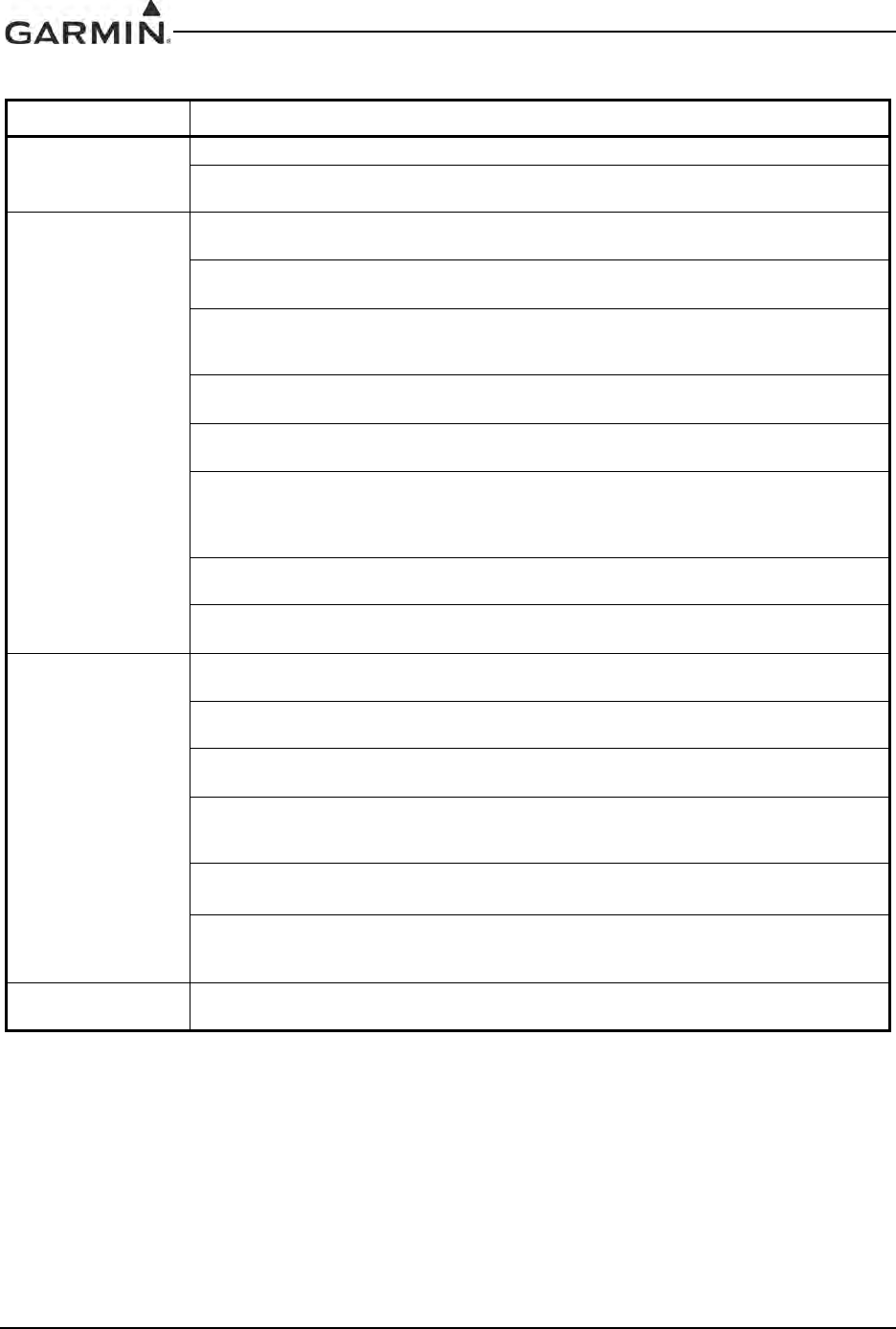
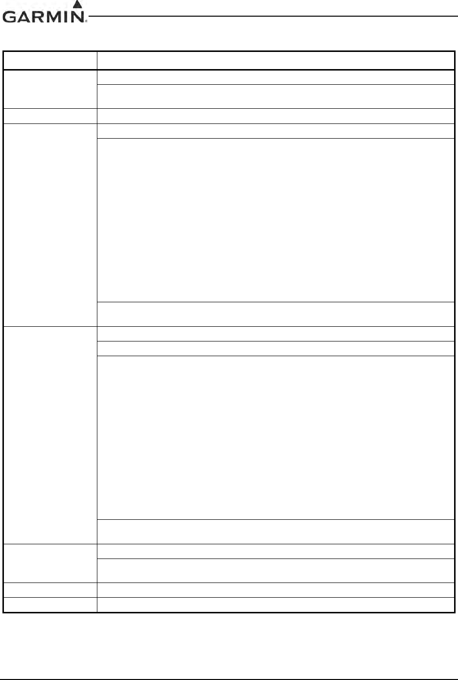
1.6.2 GIA 63 TSO/ETSO Deviations
Table 1-12. GIA 63 TSO/ETSO Deviations
TSO/ETSO Deviation
TSO-C9c 1. Garmin was granted a deviation from TSO-C9c to use SAE AS 402B instead of AS-402A.
2. Garmin was granted a deviation from TSO-C9c to use DO-160D instead of specified
environmental tests.
3. Garmin was granted a deviation from TSO-C9c subpart A (c), which requires marking the weight
of the unit on the unit. Garmin will provide this information in the installation manual in lieu of marking
on the serial tag. Garmin does not currently list the weight on other avionics units.
4. Garmin was granted a deviation from SAE AS 402B paragraph 4.4.1 to limit autopilot engagement
to attitudes considered safe for the certified aircraft.
5. Garmin was granted a deviation from SAE AS 402B paragraph 4.3.2 to not provide servo effort
indications when the automatic pilot is not engaged.
ETSO-C9c 1. Garmin was granted a deviation from ETSO-C9c to use SAE AS-402B instead of AS-402A.
2. Garmin was granted a deviation from ETSO-C9c to use DO-160D instead of the specified
environmental tests.
3. Garmin was granted a deviation from AS-402B paragraph 4.3.2 to not provide servo effort
indications when the automatic pilot is not engaged.
4. Garmin was granted a deviation from AS-402B paragraph 4.4.1 to limit autopilot engagement to
attitudes considered safe for the certified aircraft.
TSO-C34e 1. Garmin was granted a deviation from TSO-C34e to use DO-160D Change 3 instead of DO-160B,
and DO-178B instead of DO-178A.
TSO-C36e 1. Garmin was granted a deviation from TSO-C36e to use DO-160D Change 3 instead of DO-160B,
and DO-178B instead of DO-178A.
TSO-C37d 1. Garmin was granted a deviation from TSO-C37d to use DO-160D Change 3 instead of DO-160B,
and DO-178B instead of DO-178A.
2. Garmin was granted a deviation from TSO-C37d paragraph (a)(1) to allow using RTCA document
DO-186a Change 2 instead of RTCA document DO-186 to specify minimum performance standards.
3. Garmin was granted a deviation from TSO-C37d by allowing a 6dB reduction of transmitter power
during the Normal Operating Conditions - Emergency Operation Voltage as described in RTCA
document DO-186a paragraph 2.5.13.1 and RTCA document DO-160C paragraph 16.5.2.1.
4. Garmin was granted a deviation from TSO-C37d paragraph (a)(5) to allow 8.33 kHz spacing in
addition to the 25 kHz spacing.
5. Garmin was granted a deviation from TSO-C37d paragraph (b)(1) to allow the marking to call out
8.33 kHz spacing in addition to the 25 kHz spacing.
TSO-C38d 1. Garmin was granted a deviation from TSO-C38d to use DO-160D Change 3 instead of DO-160B,
and DO-178B instead of DO-178A.
2. Garmin was granted a deviation from TSO-C38d paragraph (a)(1) to allow using RTCA document
DO-186a Change 2 instead of RTCA document DO-186 to specify minimum performance standards.
3. Garmin was granted a deviation from TSO-C38d paragraph (a)(5) to allow 8.33 kHz spacing in
addition to the 25 kHz spacing.
TSO-C40c 1. Garmin was granted a deviation from TSO-C40c to use DO-160D Change 3 instead of DO-160B,
and DO-178B instead of DO-178A.
TSO-C52b 1. Garmin was granted a deviation from SAE AS 8008 paragraph 3.6 to limit flight director operation
to attitudes considered safe for the certified aircraft.
2. Garmin was granted a deviation from TSO-C52b to use DO-160D instead of DO-160C.
ETSO-C52b 1. Garmin was granted a deviation from AS-8008 paragraph 3.6 to limit flight director operation to
attitudes considered safe for the certified aircraft.
DRAFT
GIA 63 Installation Manual 190-00303-05
Page 1-16 Rev. W
TSO-C92c 1. Garmin was granted a deviation from TSO-C92c to use DO-160D Change 3 instead of DO-160C.
2. Garmin was granted a deviation from TSO-C92c to not include the version and levels of software
or the modification status of hardware in the appliance number.
TSO-C129a 1. Garmin was granted a deviation from TSO-C129a to use DO-160D Change 3 instead of DO-
160C.
2. Garmin was granted a deviation from TSO-C129a to eliminate the annunciation for pending CDI
scale change 3.0 NM from the FAF.
3. Garmin was granted a deviation from TSO-C129a involving the use of GPS calibrated altitude in
approach mode based on the enclosed TSO deviation request dated August 24, 1994 and the
approval letter dated November 29, 1994.
4. Garmin was granted a deviation from TSO-C129a to extend automatic CDI sensitivity changes to
non-approach mode navigation.
5. Garmin was granted a deviation from TSO-C129a to eliminate the requirement in (a)(3)(xi)1.b.ii to
“alert the pilot of the need to manually insert the barometric pressure”.
6. Garmin was granted a deviation from TSO-C129a to eliminate the requirement in (a)(3)(xv)4.b to
provide a “means to manually identify a satellite that is expected to be unavailable at the destination
(for scheduled maintenance as identified in FAA Notice to Airmen) shall be provided” for the RAIM
prediction process.
7. Garmin was granted a deviation from TSO-C129a to change the requirement in (a)(6)(iii) from
“The navigation data contains all 1’s or 0’s” to “All data bits in subframe 1, 2, or 3 are 0’s”.
8. Garmin was granted a deviation from TSO-C129a to change the requirement in paragraph
(a)(7)(ii) to match the WAAS TSO-C145a and DO-229 requirements for Power input testing.
ETSO-C129a 1. Garmin was granted a deviation from ED-72A 3.2.2.1.f (list item 3) and 3.2.2.4.j.4 to eliminate the
annunciation for pending CDI scale change 3.0 nm from the FAF.
2. Garmin was granted a deviation from ED-72A 3.2.2.4.j.3 to extend automatic CDI sensitivity
changes for approach mode navigation to non-approach mode navigation as well.
3. Garmin was granted a deviation from ED-72A 3.2.2.1.f (list item 4) and 3.2.2.3.e.4 and 3.2.2.4.j.2
to eliminate the requirement to alert the pilot of the need to manually insert the barometric pressure.
4. Garmin was granted a deviation from ED-72A 3.2.2.3.d.2 to eliminate the requirement to provide a
means to manually identify a satellite that is expected to be unavailable at the destination (for
scheduled maintenance as identified in FAA Notice to Airmen) for the RAIM prediction process.
5. Garmin was granted a deviation from ED-72A 3.1.4.1.c to change the requirement from
“the navigation data contains all 1’s or 0’s” to “all data bits in subframe 1,2, or 3 are 0’s”.
6. Garmin was granted a deviation from ED-72A 4.16.2 to eliminate the requirement for valid position
within 10 seconds of power interrupt for abnormal operating conditions power input tests. For
abnormal operating conditions power input tests, satellite acquisition time of 5 minutes applies.
TSO-C151b 1. Garmin was granted a deviation from TSO-C151b 4.a. to mark the unit with the serial number
instead of the date of manufacture.
Table 1-12. GIA 63 TSO/ETSO Deviations
TSO/ETSO Deviation
DRAFT
190-00303-05 GIA 63 Installation Manual
Rev. W Page 1-17
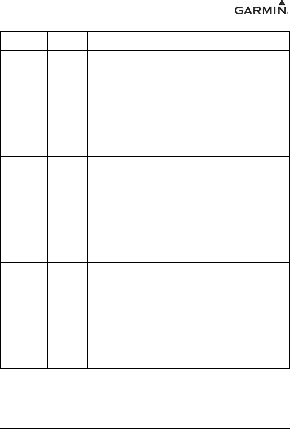
1.6.3 GIA 63W TSO/ETSO Compliance
Table 1-13. GIA 63W TSO/ETSO Compliance
Function TSO/ETSO Category Applicable LRU SW Part
Numbers Applicable CLD
Part Numbers
Automatic Pilots TSO-C9c
ETSO-C9c
All
006-B0544-1()
through
006-B0544-4()
and all
006-B0544-B()
except
006-B0544-BA
through
006-B0544-BB
All
006-C0084-0()
except
006-C0084-00
006-C0072-0()
006-C0085-0()
All
006-C0039-0()
except
006-C0039-00
through
006-C0039-02
Glideslope
Receiver
TSO-C34e
ETSO-2C34f
All
006-B0544-1()
through
006-B0544-4()
and all
006-B0544-B()
except
006-B0544-BA
through
006-B0544-BB
All
006-B0083-0()
except
006-B0083-00
through
006-B0083-01
All
006-C0084-0()
except
006-C0084-00
006-C0072-0()
006-C0085-0()
All
006-C0039-0()
except
006-C0039-00
through
006-C0039-02
Localizer
Receiver
TSO-C36e
ETSO-2C36f Class A
006-B0544-1()
through
006-B0544-4()
and all
006-B0544-B()
except
006-B0544-BA
through
006-B0544-BB
All
006-B0082-0()
except
006-B0082-00
through
006-B0082-02
All
006-C0084-0()
except
006-C0084-00
006-C0072-0()
006-C0085-0()
All
006-C0039-0()
except
006-C0039-00
through
006-C0039-02
All
006-C0053-0()
except
006-C0053-00
DRAFT
GIA 63 Installation Manual 190-00303-05
Page 1-18 Rev. W
VOR Receiver TSO-C40c
ETSO-2C40c
All
006-B0544-1()
through
006-B0544-4()
and all
006-B0544-B()
except
006-B0544-BA
through
006-B0544-BB
All
006-B0082-0()
except
006-B0082-00
through
006-B0082-02
All
006-C0084-0()
except
006-C0084-00
006-C0072-0()
006-C0085-0()
All
006-C0039-0()
except
006-C0039-00
through
006-C0039-02
All
006-C0053-0()
except
006-C0053-00
Flight Director
Equipment
TSO-C52b
ETSO-C52b
All
006-B0544-1()
through
006-B0544-4()
and all
006-B0544-B()
except
006-B0544-BA
through
006-B0544-BB
All
006-C0084-0()
except
006-C0084-00
006-C0072-0()
006-C0085-0()
All
006-C0039-0()
except
006-C0039-00
through
006-C0039-02
Stall Warning
Instruments TSO-C54 Type II
All
006-B0544-4()
and all
006-B0544-B()
except
006-B0544-BA
through
006-B0544-BB
All
006-C0084-0()
except
006-C0084-00
006-C0072-0()
006-C0085-0()
Table 1-13. GIA 63W TSO/ETSO Compliance
Function TSO/ETSO Category Applicable LRU SW Part
Numbers Applicable CLD
Part Numbers
DRAFT
190-00303-05 GIA 63 Installation Manual
Rev. W Page 1-19
Ground
Proximity
Warning – Glide
Slope Deviation
Alerting
Equipment
TSO-C92c
ETSO-C92c
All
006-B0544-3()
through
006-B0544-4()
and all
006-B0544-B()
except
006-B0544-BA
through
006-B0544-BB
All
006-C0084-0()
except
006-C0084-00
006-C0072-0()
006-C0085-0()
All
006-C0039-0()
except
006-C0039-00
through
006-C0039-02
Airborne
Navigation
Sensors Using
the Global
Positioning
System
Augmented by
the Wide Area
Augmentation
System*
TSO-C145a
ETSO-C145 Class 3
All
006-B0544-1()
through
006-B0544-4()
and all
006-B0544-B()
except
006-B0544-BA
through
006-B0544-BB
All
006-B0339-0()
except
006-B0339-00
through
006-B0339-03
All
006-C0084-0()
except
006-C0084-00
006-C0072-0()
006-C0085-0()
TAWS
TSO-C151b
ETSO-C151a Class B
All
006-B0544-1()
through
006-B0544-2()
and all
006-B0544-B()
except
006-B0544-BA
through
006-B0544-BB
All
006-C0084-0()
except
006-C0084-00
006-C0072-0()
006-C0085-0()
All
006-C0039-0()
except
006-C0039-00
through
006-C0039-02
TSO-C151b
ETSO-C151b
Class A
and B
All
006-B0544-3()
through
006-B0544-4()
and all
006-B0544-B()
except
006-B0544-BA
through
006-B0544-BB
All
006-C0084-0()
except
006-C0084-00
006-C0072-0()
006-C0085-0()
All
006-C0039-0()
except
006-C0039-00
through
006-C0039-02
Table 1-13. GIA 63W TSO/ETSO Compliance
Function TSO/ETSO Category Applicable LRU SW Part
Numbers Applicable CLD
Part Numbers
DRAFT
GIA 63 Installation Manual 190-00303-05
Page 1-20 Rev. W
VHF Radio
Communications
Transceiver
Equipment
TSO-C169
Equivalent to
ETSO-2C37e
&
ETSO-2C38e
Class 3
and 5
(transmitter)
Class C
and E
(receiver)
All
006-B0544-1()
through
006-B0544-4()
and all
006-B0544-B()
except
006-B0544-BA
through
006-B0544-BB
All
006-B0081-0()
except
006-B0081-00
through
006-B0081-04
All
006-C0084-0()
except
006-C0084-00
006-C0072-0()
006-C0085-0()
All
006-C0039-0()
except
006-C0039-00
through
006-C0039-02
*GIA63W ARINC output labels 310 and 311 are not to be used as navigation data per RTCA/DO-229c.
Table 1-13. GIA 63W TSO/ETSO Compliance
Function TSO/ETSO Category Applicable LRU SW Part
Numbers Applicable CLD
Part Numbers
DRAFT

190-00303-05 GIA 63 Installation Manual
Rev. W Page 1-21
1.6.4 GIA 63W TSO/ETSO Deviations
Table 1-14. GIA 63W TSO/ETSO Deviations
TSO/ETSO Deviation
TSO-C9c 1. Garmin was granted a deviation from TSO-C9c to use SAE AS 402B instead of AS-402A.
2. Garmin was granted a deviation from TSO-C9c to use DO-160E instead of specified
environmental tests.
3. Garmin was granted a deviation from TSO-C9c subpart A (c), which requires marking the weight
of the unit on the unit. Garmin will provide this information in the installation manual in lieu of marking
on the serial tag. Garmin does not currently list the weight on other avionics units.
4. Garmin was granted a deviation from SAE AS 402B paragraph 4.4.1 to limit autopilot engagement
to attitudes considered safe for the certified aircraft.
5. Garmin was granted a deviation from SAE AS 402B paragraph 4.3.2 to not provide servo effort
indications when the automatic pilot is not engaged.
ETSO-C9c 1. Garmin was granted a deviation from ETSO-C9c to use SAE AS-402B instead of AS-402A.
2. Garmin was granted a deviation from ETSO-C9c to use DO-160E instead of the specified
environmental tests.
3. Garmin was granted a deviation from AS-402B paragraph 4.3.2 to not provide servo effort
indications when the automatic pilot is not engaged.
4. Garmin was granted a deviation from AS-402B paragraph 4.4.1 to limit autopilot engagement to
attitudes considered safe for the certified aircraft.
TSO-C34e 1. Garmin was granted a deviation from TSO-C34e to use DO-160E instead of DO-160B, and
DO-178B instead of DO-178A.
ETSO-2C34f 1. Garmin was granted a deviation from ETSO-2C34f to use DO-160E instead of DO-160D.
TSO-C36e 1. Garmin was granted a deviation from TSO-C36e to use DO-160E instead of DO-160B, and
DO-178B instead of DO-178A.
ETSO-2C36f 1. Garmin was granted a deviation from ETSO-2C36f to use DO-160E instead of DO-160D.
2. Garmin was granted a deviation from ETSO-2C36f to use ED-46B amendment 2 in addition to ED
46B.
ETSO-2C37e 1. Garmin was granted a deviation from ETSO-2C37e to use DO-160E instead of DO-160D.
2. Garmin was granted a deviation from ETSO-2C37e to use ED-23B amendment 3 in addition to
ED-23B.
ETSO-2C38e 1. Garmin was granted a deviation from ETSO-2C38e to use DO-160E instead of DO-160D.
2. Garmin was granted a deviation from ETSO-2C38e to use ED-23B amendment 3 in addition to
ED-23B.
TSO-C40c 1. Garmin was granted a deviation from TSO-C40c to use DO-160E instead of DO-160B, and
DO-178B instead of DO-178A.
ETSO-2C40c 1. Garmin was granted a deviation from ETSO-2C40c to use DO-160E instead of DO-160D.
2. Garmin was granted a deviation from ED-22B paragraph 5.2.9 to have a deflection response of
0.5 to 2.7 seconds instead of 0.5 to 2 seconds.
TSO-C52b 1. Garmin was granted a deviation from SAE AS 8008 paragraph 3.6 to limit flight director operation
to attitudes considered safe for the certified aircraft.
2. Garmin was granted a deviation from TSO-C52b to use DO-160E instead of DO-160C. The
justification for this deviation is to use the latest accepted environmental standards.
ETSO-C52b 1. Garmin was granted a deviation from ETSO-C52b to use DO-160E instead of DO-160D.
2. Garmin was granted a deviation from AS-8008 paragraph 3.6 to limit flight director operation to
attitudes considered safe for the certified aircraft.
TSO-C54 1. Garmin was granted a deviation from TSO-C54 to use RTCA DO-160E instead of SAE AS 403A.
DRAFT
GIA 63 Installation Manual 190-00303-05
Page 1-22 Rev. W
TSO-C92c 1. Garmin was granted a deviation from TSO-C92c to use DO-160E instead of DO-160C.
2. Garmin was granted a deviation from TSO-C92c to not include the version and levels of software
or the modification status of hardware in the appliance number.
ETSO-C92c 1. Garmin was granted a deviation from ETSO-C92c to use DO-160E instead of DO-160D.
TSO-C145a 1. Garmin was granted a deviation from TSO-C145a to use DO-160E instead of DO-160D.
2. Garmin was granted a deviation from RTCA/DO-229C paragraphs 2.1.1.10, 2.1.1.7,
2.1.1.8.1, 2.1.1.8.2, 2.1.1.9, 2.1.2.1, 2.1.3.1, 2.1.4.1.4, 2.1.4.1.5 and 2.1.5.1 in the form of an
operational limitation to achieve an equivalent level of safety. This operational limitation applies to
the GIA63W with GPS software version 2.40 or earlier, or GIA63W installations with certain models
of GPS/WAAS antennas identified in Section 2.1.3.2. The operational limitation is based on:
1. The ability to use antennas that may not meet the minimum gain performance requirements of
DO-228.
2. The ability to mitigate the effects of the different gain characteristics of those antennas by
increasing the effective mask angle through operational limitations.
3. The ability to further increase the effective mask angle, through operational limitations, to a level
commensurate with test conditions used in the original TSO qualification tests.
4. The ability to use -128 dBmic as the minimum GPS satellite signal-in-space for the purpose of
assessing the operational limitation.
5. The ability to use -128 dBmic as the minimum SBAS satellite signal-in-space for the purpose of
assessing the operational limitation.
3. Garmin was granted a deviation from RTCA/DO-229C paragraph 2.1.1.9 to use a 20 second
satellite reacquisition time instead of a 10-second reacquisition time.
ETSO-C145 1. Garmin was granted a deviation from ETSO-C145 to use DO-160E instead of DO-160D
2. Garmin was granted a deviation from ETSO-C145 to use DO-229C instead of DO-229A
3. Garmin was granted a deviation from DO-229C paragraphs 2.1.1.10, 2.1.1.7, 2.1.1.8.1,
2.1.1.8.2, 2.1.1.9, 2.1.2.1, 2.1.3.1, 2.1.4.1.4, 2.1.4.1.5 and 2.1.5.1 in the form of an operational
limitation to achieve an equivalent level of safety. This operational limitation applies to the GIA63W
with GPS software version 2.40 or earlier, or GIA63W installations with certain models of GPS/
WAAS antennas identified in Section 2.1.3.2. The operational limitation is based on:
1. The ability to use antennas that may not meet the minimum gain performance requirements of
DO-228.
2. The ability to mitigate the effects of the different gain characteristics of those antennas by
increasing the effective mask angle through operational limitations.
3. The ability to further increase the effective mask angle, through operational limitations, to a level
commensurate with test conditions used in the original TSO qualification tests.
4. The ability to use -128 dBmic as the minimum GPS satellite signal-in-space for the purpose of
assessing the operational limitation.
5. The ability to use -128 dBmic as the minimum SBAS satellite signal-in-space for the purpose of
assessing the operational limitation.
4. Garmin was granted a deviation from RTCA/DO-229C paragraph 2.1.1.9 to use a 20 second
satellite reacquisition time instead of a 10-second reacquisition time.
TSO-C151b 1. Garmin was granted a deviation from TSO-C151b to use DO-160E instead of DO-160D.
2. Garmin was granted a deviation from TSO-C151b 4.a. to mark the unit with the serial number
instead of the date of manufacture.
ETSO-C151a 1. Garmin was granted a deviation from ETSO-C151a to use DO-160E instead of DO-160D.
ETSO-C151b 1. Garmin was granted a deviation from ETSO-C151b to use DO-160E instead of DO-160D.
Table 1-14. GIA 63W TSO/ETSO Deviations
TSO/ETSO Deviation
DRAFT
190-00303-05 GIA 63 Installation Manual
Rev. W Page 1-23
TSO-C169 1. Garmin was granted a deviation from TSO-C169 to use DO-160E instead of DO-160D.
2. Garmin was granted a deviation to TSO-C169, paragraph 4.d requirement to mark the installation
procedures drawing number on the equipment. Garmin will mark as follows, which Garmin believes
meets the intent of the requirement. The Install Manual is part of the furnished data package.
TSO-C145a
See Install Manual for additional appliance approvals
3. Garmin was granted a deviation to TSO-C169, paragraph 4.e requirement to mark (DEV) after the
TSO number on the equipment. Garmin will mark as follows, as TSOC169 is not the primary TSO
and the Install Manual contains all of the TSO-C169 information including deviations.
TSO-C145a
See Install Manual for additional appliance approvals
4. Garmin was granted to deviate from TSO-C169 by allowing a 6dB reduction of transmitter power
during the Normal Operating Conditions – Emergency Operation Voltage as described in RTCA
document DO-186a paragraph 2.5.13.1 and RTCA document DO-160E paragraph 16.6.1.1.
Table 1-14. GIA 63W TSO/ETSO Deviations
TSO/ETSO Deviation
DRAFT
GIA 63 Installation Manual 190-00303-05
Page 1-24 Rev. W
1.6.5 GIA 63W Updated NAV/COM TSO/ETSO Compliance
Table 1-15. GIA 63W Updated NAV/COM TSO/ETSO Compliance
Function TSO/ETSO Category Applicable LRU SW Part
Numbers Applicable CLD
Part Numbers
Automatic Pilots TSO-C9c
ETSO-C9c
All
006-B0544-3()
through
006-B0544-4()
except
006-B0544-30
through
006-B0544-34
and all
006-B0544-B()
except
006-B0544-BA
through
006-B0544-BD
All
006-C0084-0()
except
006-C0084-00
006-C0072-0()
006-C0085-0()
Glideslope
Receiver
TSO-C34e
ETSO-2C34f
All
006-B0544-3()
through
006-B0544-4()
except
006-B0544-30
through
006-B0544-34
and all
006-B0544-B()
except
006-B0544-BA
through
006-B0544-BD
All
006-B0082-1()
except
006-B0082-10
All
006-C0084-0()
except
006-C0084-00
006-C0072-0()
006-C0085-0()
Localizer
Receiver
TSO-C36e
ETSO-2C36f Class A
All
006-B0544-3()
through
006-B0544-4()
except
006-B0544-30
through
006-B0544-34
and all
006-B0544-B()
except
006-B0544-BA
through
006-B0544-BD
All
006-B0082-1()
except
006-B0082-10
All
006-C0084-0()
except
006-C0084-00
006-C0072-0()
006-C0085-0()
006-C0124-0()
DRAFT
190-00303-05 GIA 63 Installation Manual
Rev. W Page 1-25
VOR Receiver TSO-C40c
ETSO-2C40c
All
006-B0544-3()
through
006-B0544-4()
except
006-B0544-30
through
006-B0544-34
and all
006-B0544-B()
except
006-B0544-BA
through
006-B0544-BD
All
006-B0082-1()
except
006-B0082-10
All
006-C0084-0()
except
006-C0084-00
006-C0072-0()
006-C0085-0()
006-C0124-0()
Flight Director
Equipment
TSO-C52b
ETSO-C52b
All
006-B0544-3()
through
006-B0544-4()
except
006-B0544-30
through
006-B0544-34
and all
006-B0544-B()
except
006-B0544-BA
through
006-B0544-BD
All
006-C0084-0()
except
006-C0084-00
006-C0072-0()
006-C0085-0()
Stall Warning
Instruments TSO-C54 Type II
All
006-B0544-4()
and all
006-B0544-B()
except
006-B0544-BA
through
006-B0544-BD
All
006-C0084-0()
except
006-C0084-00
006-C0072-0()
006-C0085-0()
Table 1-15. GIA 63W Updated NAV/COM TSO/ETSO Compliance
Function TSO/ETSO Category Applicable LRU SW Part
Numbers Applicable CLD
Part Numbers
DRAFT

GIA 63 Installation Manual 190-00303-05
Page 1-26 Rev. W
Ground Proximity
Warning – Glide
Slope Deviation
Alerting
Equipment
TSO-C92c
ETSO-C92c
All
006-B0544-3()
through
006-B0544-4()
except
006-B0544-30
through
006-B0544-34
and all
006-B0544-B()
except
006-B0544-BA
through
006-B0544-BD
All
006-C0084-0()
except
006-C0084-00
006-C0072-0()
006-C0085-0()
Table 1-15. GIA 63W Updated NAV/COM TSO/ETSO Compliance
Function TSO/ETSO Category Applicable LRU SW Part
Numbers Applicable CLD
Part Numbers
DRAFT
190-00303-05 GIA 63 Installation Manual
Rev. W Page 1-27
Airborne
Navigation
Sensors Using
the Global
Positioning
System
Augmented by
the Wide Area
Augmentation
System*
TSO-C145a
ETSO-C145 Class 3
All
006-B0544-3()
through
006-B0544-4()
except
006-B0544-30
through
006-B0544-34
and all
006-B0544-B()
except
006-B0544-BA
through
006-B0544-BD
All
006-B0339-0()
except
006-B0339-00
through
006-B0339-03
All
006-C0084-0()
except
006-C0084-00
006-C0072-0()
006-C0085-0()
TAWS TSO-C151b
ETSO-C151b
Class A
and B
All
006-B0544-3()
through
006-B0544-4()
except
006-B0544-30
through
006-B0544-34
and all
006-B0544-B()
except
006-B0544-BA
through
006-B0544-BD
All
006-C0084-0()
except
006-C0084-00
006-C0072-0()
006-C0085-0()
VHF Radio
Communications
Transceiver
Equipment
TSO-C169a
Equivalent to
ETSO-2C37e
&
ETSO-2C38e
Class 3, 4,
5, and 6
(transmitter)
Class C and
E
(receiver)
All
006-B0544-3()
through
006-B0544-4()
except
006-B0544-30
through
006-B0544-34
and all
006-B0544-B()
except
006-B0544-BA
through
006-B0544-BD
006-B0081-1()
All
006-C0084-0()
except
006-C0084-00
006-C0072-0()
006-C0085-0()
*GIA 63W ARINC output labels 310 and 311 are not to be used as navigation data per RTCA/DO-229c.
Table 1-15. GIA 63W Updated NAV/COM TSO/ETSO Compliance
Function TSO/ETSO Category Applicable LRU SW Part
Numbers Applicable CLD
Part Numbers
DRAFT

GIA 63 Installation Manual 190-00303-05
Page 1-28 Rev. W
1.6.6 GIA 63H TSO/ETSO Compliance
Table 1-16. GIA 63H TSO/ETSO Compliance
Function TSO/ETSO Category Applicable LRU SW Part
Numbers Applicable CLD
Part Numbers
Automatic Pilots TSO-C9c
ETSO-C9c
All
006-B0544-3()
through
006-B0544-4()
except
006-B0544-30
through
006-B0544-35
and all
006-B0544-B()
except
006-B0544-BA
through
006-B0544-BD
All
006-C0084-0()
except
006-C0084-00
006-C0072-0()
006-C0085-0()
Glideslope
Receiver
TSO-C34e
ETSO-2C34f
All
006-B0544-3()
through
006-B0544-4()
except
006-B0544-30
through
006-B0544-35
and all
006-B0544-B()
except
006-B0544-BA
through
006-B0544-BD
All
006-B0082-1()
except
006-B0082-10
All
006-C0084-0()
except
006-C0084-00
006-C0072-0()
006-C0085-0()
Localizer
Receiver
TSO-C36e
ETSO-2C36f Class A
All
006-B0544-3()
through
006-B0544-4()
except
006-B0544-30
through
006-B0544-35
and all
006-B0544-B()
except
006-B0544-BA
through
006-B0544-BD
All
006-B0082-1()
except
006-B0082-10
All
006-C0084-0()
except
006-C0084-00
006-C0072-0()
006-C0085-0()
006-C0124-0()
DRAFT

190-00303-05 GIA 63 Installation Manual
Rev. W Page 1-29
VOR Receiver TSO-C40c
ETSO-2C40c
All
006-B0544-3()
through
006-B0544-4()
except
006-B0544-30
through
006-B0544-35
and all
006-B0544-B()
except
006-B0544-BA
through
006-B0544-BD
All
006-B0082-1()
except
006-B0082-10
All
006-C0084-0()
except
006-C0084-00
006-C0072-0()
006-C0085-0()
006-C0124-0()
Flight Director
Equipment
TSO-C52b
ETSO-C52b
All
006-B0544-3()
through
006-B0544-4()
except
006-B0544-30
through
006-B0544-35
and all
006-B0544-B()
except
006-B0544-BA
through
006-B0544-BD
All
006-C0084-0()
except
006-C0084-00
006-C0072-0()
006-C0085-0()
Stall Warning
Instruments TSO-C54 Type II
All
006-B0544-4()
and all
006-B0544-B()
except
006-B0544-BA
through
006-B0544-BD
All
006-C0084-0()
except
006-C0084-00
006-C0072-0()
006-C0085-0()
Table 1-16. GIA 63H TSO/ETSO Compliance
Function TSO/ETSO Category Applicable LRU SW Part
Numbers Applicable CLD
Part Numbers
DRAFT
GIA 63 Installation Manual 190-00303-05
Page 1-30 Rev. W
Ground Proximity
Warning – Glide
Slope Deviation
Alerting
Equipment
TSO-C92c
ETSO-C92c
All
006-B0544-3()
through
006-B0544-4()
except
006-B0544-30
through
006-B0544-35
and all
006-B0544-B()
except
006-B0544-BA
through
006-B0544-BD
All
006-C0084-0()
except
006-C0084-00
006-C0072-0()
006-C0085-0()
Airborne
Navigation
Sensors Using
the Global
Positioning
System
Augmented by
the Wide Area
Augmentation
System*
TSO-C145a
ETSO-C145 Class 3
All
006-B0544-3()
through
006-B0544-4()
except
006-B0544-30
through
006-B0544-35
and all
006-B0544-B()
except
006-B0544-BA
through
006-B0544-BD
All
006-B0339-0()
except
006-B0339-00
through
006-B0339-03
All
006-C0084-0()
except
006-C0084-00
006-C0072-0()
006-C0085-0()
TAWS TSO-C151b
ETSO-C151b
Class A
and B
All
006-B0544-3()
through
006-B0544-4()
except
006-B0544-30
through
006-B0544-35
and all
006-B0544-B()
except
006-B0544-BA
through
006-B0544-BD
All
006-C0084-0()
except
006-C0084-00
006-C0072-0()
006-C0085-0()
Table 1-16. GIA 63H TSO/ETSO Compliance
Function TSO/ETSO Category Applicable LRU SW Part
Numbers Applicable CLD
Part Numbers
DRAFT
190-00303-05 GIA 63 Installation Manual
Rev. W Page 1-31
VHF Radio
Communications
Transceiver
Equipment
TSO-C169a
Equivalent to
ETSO-2C37e
&
ETSO-2C38e
Class 3, 4,
5, and 6
(transmitter)
Class C and
E
(receiver)
All
006-B0544-3()
through
006-B0544-4()
except
006-B0544-30
through
006-B0544-35
and all
006-B0544-B()
except
006-B0544-BA
through
006-B0544-BD
006-B0081-1()
All
006-C0084-0()
except
006-C0084-00
006-C0072-0()
006-C0085-0()
*GIA 63H ARINC output labels 310 and 311 are not to be used as navigation data per RTCA/DO-229c.
Table 1-16. GIA 63H TSO/ETSO Compliance
Function TSO/ETSO Category Applicable LRU SW Part
Numbers Applicable CLD
Part Numbers
DRAFT
GIA 63 Installation Manual 190-00303-05
Page 1-32 Rev. W
1.6.7 GIA 63W Updated NAV/COM and GIA 63H TSO/ETSO Deviations
Table 1-17. GIA 63W Updated NAV/COM and GIA 63H TSO/ETSO Deviations
TSO/ETSO Deviation
TSO-C9c 1. Garmin was granted a deviation from TSO-C9c to use SAE AS 402B instead of AS-402A.
2. Garmin was granted a deviation from TSO-C9c to use DO-160E instead of specified
environmental tests.
3. Garmin was granted a deviation from TSO-C9c subpart A (c), which requires marking the weight
of the unit on the unit. Garmin will provide this information in the installation manual in lieu of marking
on the serial tag. Garmin does not currently list the weight on other avionics units.
4. Garmin was granted a deviation from SAE AS 402B paragraph 4.4.1 to limit autopilot engagement
to attitudes considered safe for the certified aircraft.
5. Garmin was granted a deviation from SAE AS 402B paragraph 4.3.2 to not provide servo effort
indications when the automatic pilot is not engaged.
ETSO-C9c 1. Garmin was granted a deviation from ETSO-C9c to use SAE AS-402B instead of AS-402A.
2. Garmin was granted a deviation from ETSO-C9c to use DO-160E instead of the specified
environmental tests.
3. Garmin was granted a deviation from AS-402B paragraph 4.3.2 to not provide servo effort
indications when the automatic pilot is not engaged.
4. Garmin was granted a deviation from AS-402B paragraph 4.4.1 to limit autopilot engagement to
attitudes considered safe for the certified aircraft.
TSO-C34e 1. Garmin was granted a deviation from TSO-C34e to use DO-160E instead of DO-160B, and
DO-178B instead of DO-178A
ETSO-2C34f 1. Garmin was granted a deviation from ETSO-2C34f to use DO-160E instead of DO-160D.
TSO-C36e 1. Garmin was granted a deviation from TSO-C36e to use DO-160E instead of DO-160B, and
DO-178B instead of DO-178A.
ETSO-2C36f 1. Garmin was granted a deviation from ETSO-2C36f to use DO-160E instead of DO-160D.
2. Garmin was granted a deviation from ETSO-2C36f to use ED-46B amendment 2 in addition to ED
46B.
ETSO-2C37e 1. Garmin was granted a deviation from ETSO-2C37e to use DO-160E instead of DO-160D.
2. Garmin was granted a deviation from ETSO-2C37e to use ED-23B amendment 3 in addition to
ED-23B.
ETSO-2C38e 1. Garmin was granted a deviation from ETSO-2C38e to use DO-160E instead of DO-160D.
2. Garmin was granted a deviation from ETSO-2C38e to use ED-23B amendment 3 in addition to
ED-23B.
TSO-C40c 1. Garmin was granted a deviation from TSO-C40c to use DO-160E instead of DO-160B, and
DO-178B instead of DO-178A.
ETSO-2C40c 1. Garmin was granted a deviation from ETSO-2C40c to use DO-160E instead of DO-160D.
2. Garmin was granted a deviation from ED-22B paragraph 5.2.9 to have a deflection response of
0.5 to 2.7 seconds instead of 0.5 to 2 seconds.
TSO-C52b 1. Garmin was granted a deviation from SAE AS 8008 paragraph 3.6 to limit flight director
operation to attitudes considered safe for the certified aircraft.
2. Garmin was granted a deviation from TSO-C52b to use DO-160E instead of DO-160C. The
justification for this deviation is to use the latest accepted environmental standards.
ETSO-C52b 1. Garmin was granted a deviation from ETSO-C52b to use DO-160E instead of DO-160D.
2. Garmin was granted a deviation from AS-8008 paragraph 3.6 to limit flight director operation to
attitudes considered safe for the certified aircraft.
TSO-C54 1. Garmin was granted a deviation from TSO-C54 to use RTCA DO-160E instead of SAE AS 403A.
DRAFT
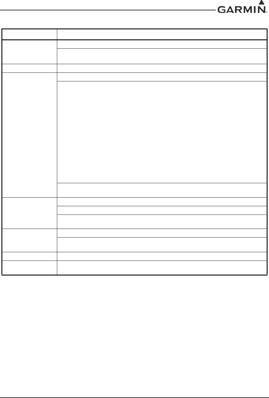
190-00303-05 GIA 63 Installation Manual
Rev. W Page 1-33
TSO-C92c 1. Garmin was granted a deviation from TSO-C92c to use DO-160E instead of DO-160C.
2. Garmin was granted a deviation from TSO-C92c to not include the version and levels of
software or the modification status of hardware in the appliance number.
ETSO-C92c 1. Garmin was granted a deviation from ETSO-C92c to use DO-160E instead of DO-160D.
TSO-C145a 1. Garmin was granted a deviation from TSO-C145a to use DO-160E instead of DO-160D.
2. Garmin was granted a deviation from RTCA/DO-229C paragraphs 2.1.1.10, 2.1.1.7,
2.1.1.8.1, 2.1.1.8.2, 2.1.1.9, 2.1.2.1, 2.1.3.1, 2.1.4.1.4, 2.1.4.1.5 and 2.1.5.1 in the form of an
operational limitation to achieve an equivalent level of safety. This operational limitation applies to
the GIA63W or GIA 63H with GPS software version 2.40 or earlier, or GIA63W or GIA 63H
installations with certain models of GPS/WAAS antennas identified in Section 2.1.3.2. The
operational limitation is based on:
1. The ability to use antennas that may not meet the minimum gain performance requirements of
DO-228.
2. The ability to mitigate the effects of the different gain characteristics of those antennas by
increasing the effective mask angle through operational limitations.
3. The ability to further increase the effective mask angle, through operational limitations, to a level
commensurate with test conditions used in the original TSO qualification tests.
4. The ability to use -128 dBmic as the minimum GPS satellite signal-in-space for the purpose of
assessing the operational limitation.
5. The ability to use -128 dBmic as the minimum SBAS satellite signal-in-space for the purpose of
assessing the operational limitation.
3. Garmin was granted a deviation from RTCA/DO-229C paragraph 2.1.1.9 to use a 20 second
satellite reacquisition time instead of a 10-second reacquisition time.
ETSO-C145 1. Garmin was granted a deviation from ETSO-C145 to use DO-160E instead of DO-160D.
2. Garmin was granted a deviation from ETSO-C145 to use DO-229C instead of DO-229A.
3. Garmin was granted a deviation from DO-229C paragraph 2.1.1.9 to use a 20 second satellite
reacquisition time instead of a 10 second reacquisition time.
TSO-C151b 1. Garmin was granted a deviation from TSO-C151b to use DO-160E instead of DO-160D.
2. Garmin was granted a deviation from TSO-C151b 4.a. to mark the unit with the serial number
instead of the date of manufacture.
ETSO-C151b 1. Garmin was granted a deviation from ETSO-C151b to use DO-160E instead of DO-160D.
TSO-C169a 1. Garmin was granted a deviation from TSO-C169a paragraph 4.a.2 to allow the unit to be
permanently and legibly marked with a serial number and not the date of manufacture.
Table 1-17. GIA 63W Updated NAV/COM and GIA 63H TSO/ETSO Deviations
TSO/ETSO Deviation
DRAFT
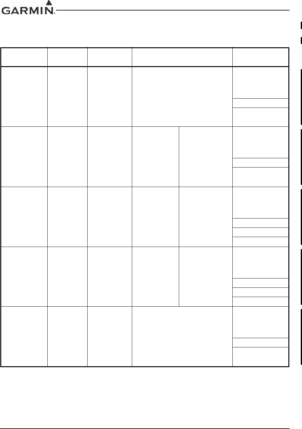
GIA 63 Installation Manual 190-00303-05
Page 1-34 Rev. W
1.6.8 GIA 63W with Enhanced COM TSO/ETSO Compliance
Table 1-18. GIA 63W with Enhanced COM TSO/ETSO Compliance
Function TSO/ETSO Category Applicable LRU SW Part
Numbers Applicable CLD
Part Numbers
Automatic Pilots TSO-C9c
All
006-B0544-4()
and all
006-B0544-B()
except
006-B0544-BA
through
006-B0544-BD
All
006-C0084-0()
except
006-C0084-00
006-C0072-0()
006-C0085-0()
Glideslope
Receiver TSO-C34e
All
006-B0544-4()
and all
006-B0544-B()
except
006-B0544-BA
through
006-B0544-BD
All
006-B0082-1()
except
006-B0082-10
All
006-C0084-0()
except
006-C0084-00
006-C0072-0()
006-C0085-0()
Localizer
Receiver TSO-C36e Class A
All
006-B0544-4()
and all
006-B0544-B()
except
006-B0544-BA
through
006-B0544-BD
All
006-B0082-1()
except
006-B0082-10
All
006-C0084-0()
except
006-C0084-00
006-C0072-0()
006-C0085-0()
006-C0124-0()
VOR Receiver TSO-C40c
All
006-B0544-4()
and all
006-B0544-B()
except
006-B0544-BA
through
006-B0544-BD
All
006-B0082-1()
except
006-B0082-10
All
006-C0084-0()
except
006-C0084-00
006-C0072-0()
006-C0085-0()
006-C0124-0()
Flight Director
Equipment TSO-C52b
All
006-B0544-4()
and all
006-B0544-B()
except
006-B0544-BA
through
006-B0544-BD
All
006-C0084-0()
except
006-C0084-00
006-C0072-0()
006-C0085-0()
DRAFT
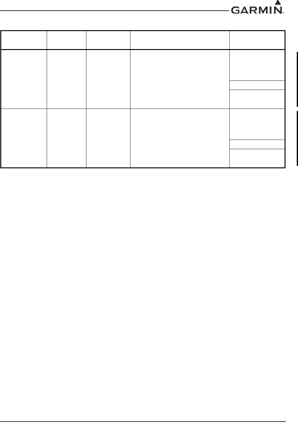
190-00303-05 GIA 63 Installation Manual
Rev. W Page 1-35
Stall Warning
Instruments TSO-C54 Type II
All
006-B0544-4()
and all
006-B0544-B()
except
006-B0544-BA
through
006-B0544-BD
All
006-C0084-0()
except
006-C0084-00
006-C0072-0()
006-C0085-0()
Ground Proximity
Warning – Glide
Slope Deviation
Alerting
Equipment
TSO-C92c
All
006-B0544-4()
and all
006-B0544-B()
except
006-B0544-BA
through
006-B0544-BD
All
006-C0084-0()
except
006-C0084-00
006-C0072-0()
006-C0085-0()
Table 1-18. GIA 63W with Enhanced COM TSO/ETSO Compliance
Function TSO/ETSO Category Applicable LRU SW Part
Numbers Applicable CLD
Part Numbers
DRAFT
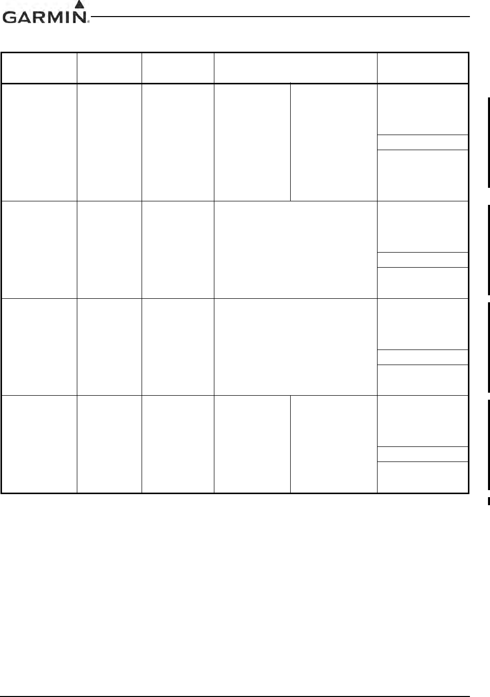
GIA 63 Installation Manual 190-00303-05
Page 1-36 Rev. W
Airborne
Navigation
Sensors Using
the Global
Positioning
System
Augmented by
the Wide Area
Augmentation
System*
TSO-C145c Class 3
All
006-B0544-4()
and all
006-B0544-B()
except
006-B0544-BA
through
006-B0544-BD
006-B0339-2()
All
006-C0084-0()
except
006-C0084-00
006-C0072-0()
006-C0085-0()
TAWS TSO-C151b Class A
and B
All
006-B0544-4()
and all
006-B0544-B()
except
006-B0544-BA
through
006-B0544-BD
All
006-C0084-0()
except
006-C0084-00
006-C0072-0()
006-C0085-0()
VDL Mode 2
Communications
Equipment
TSO-C160 Architecture
Class Z
All
006-B0544-4()
and all
006-B0544-B()
except
006-B0544-BA
through
006-B0544-BD
All
006-C0084-0()
except
006-C0084-00
006-C0072-0()
006-C0085-0()
VHF Radio
Communications
Transceiver
Equipment
TSO-C169a
Class 3, 4,
5, and 6
(transmitter)
Class C and
E
(receiver)
All
006-B0544-4()
and all
006-B0544-B()
except
006-B0544-BA
through
006-B0544-BD
006-B0081-1()
All
006-C0084-0()
except
006-C0084-00
006-C0072-0()
006-C0085-0()
*GIA 63W with Enhanced COM ARINC output labels 310 and 311 are not to be used as navigation data per RTCA/DO-229D
Table 1-18. GIA 63W with Enhanced COM TSO/ETSO Compliance
Function TSO/ETSO Category Applicable LRU SW Part
Numbers Applicable CLD
Part Numbers
DRAFT
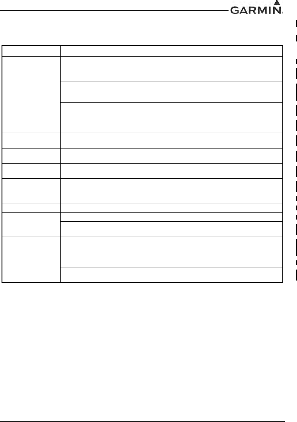
190-00303-05 GIA 63 Installation Manual
Rev. W Page 1-37
1.6.9 GIA 63W with Enhanced COM TSO/ETSO Deviations
Table 1-19. GIA 63W with Enhanced COM TSO/ETSO Deviations
TSO/ETSO Deviation
TSO-C9c 1. Garmin was granted a deviation from TSO-C9c to use SAE AS 402B instead of AS-402A.
2. Garmin was granted a deviation from TSO-C9c to use DO-160E instead of specified environmen-
tal tests
3. Garmin was granted a deviation from TSO-C9c subpart A (c), which requires marking the weight
of the unit on the unit. Garmin will provide this information in the installation manual in lieu of marking
on the serial tag. Garmin does not currently list the weight on other avionics units.
4. Garmin was granted a deviation from SAE AS 402B paragraph 4.4.1 to limit autopilot engagement
to attitudes considered safe for the certified aircraft.
5. Garmin was granted a deviation from SAE AS 402B paragraph 4.3.2 to not provide servo effort
indications when the automatic pilot is not engaged.
TSO-C34e 1. Garmin was granted a deviation from TSO-C34e to use DO-160E instead of DO-160B, and DO-
178B instead of DO-178A.
TSO-C36e 1. Garmin was granted a deviation from TSO-C36e to use DO-160E instead of DO-160B, and DO-
178B instead of DO-178A.
TSO-C40c 1. Garmin was granted a deviation from TSO-C40c to use DO-160E instead of DO-160B, and DO-
178B instead of DO-178A.
TSO-C52b 1. Garmin was granted a deviation from SAE AS 8008 paragraph 3.6 to limit flight director operation
to attitudes considered safe for the certified aircraft.
2. Garmin was granted a deviation from TSO-C52b to use DO-160E instead of DO-160C.
TSO-C54 1. Garmin was granted a deviation from TSO-C54 to use RTCA DO-160E instead of SAE AS 403A.
TSO-C92c 1. Garmin was granted a deviation from TSO-C92c to use DO-160E instead of DO-160C.
2. Garmin was granted a deviation from TSO-C92c paragraph b.(2) to not include the version and
levels of software or the modification status of hardware in the appliance part number.
TSO-C145c 1. Garmin was granted a deviation from RTCA/DO-229D paragraph 2.1.1.10 to use GPS antennas
that meet Garmin minimum performance specifications (Doc No. 004-00287-00) instead of DO-301
qualified antennas.
TSO-C151b 1. Garmin was granted a deviation from TSO-C151b to use DO-160E instead of DO-160D.
2. Garmin was granted a deviation from TSO-C151b 4.a. to mark the unit with the serial number
instead of the date of manufacture.
DRAFT
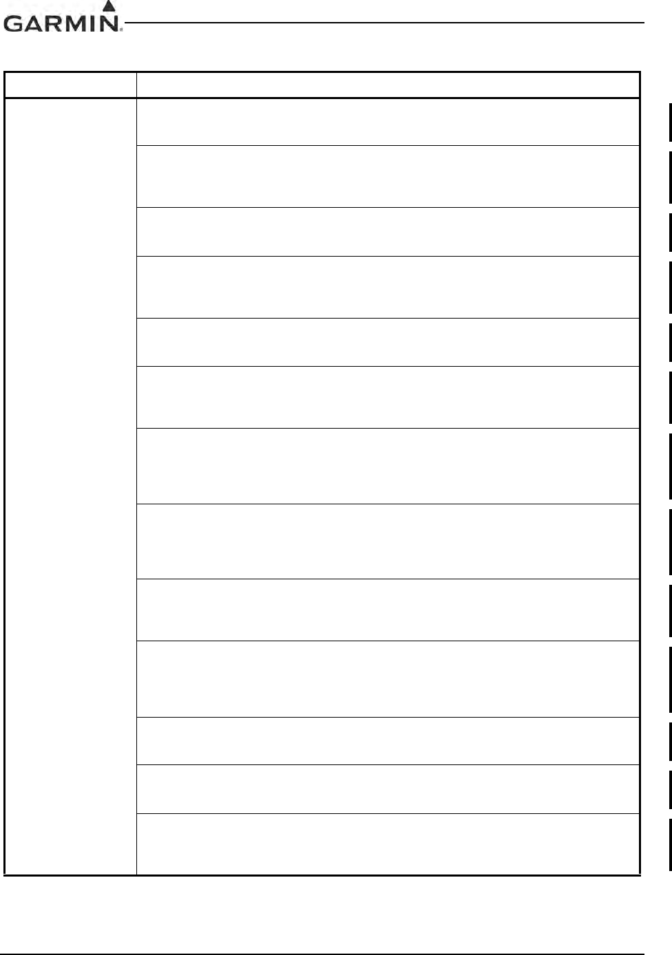
GIA 63 Installation Manual 190-00303-05
Page 1-38 Rev. W
TSO-C160 1. Garmin was granted a deviation from RTCA/DO-224B paragraph 3.2.2.5.4.7 to meet Attachment
2, Table 2-1-3, Item HO-argi of ARINC 631-5, which states that neither the VDL ground station or air-
craft will support aircraft requested ground initiated handoffs.
2. Garmin was granted a deviation from RTCA/DO-224B table 3-7 to allow the lower bound of the
aircraft T4 parameter to be 1 minute as defined in Attachment 2, Table 2-3-2, Item aT4.min of ARINC
631-5, which will supercede the value of 10 minutes defined by the aircraft T4 parameter in RTCA/
DO-224B table 3-7.
3. Garmin was granted a deviation from RTCA/DO-224B table 3-18 to allow bit 7 to be set as defined
in paragraph 7.9 of ARINC 631-5 so that the air/ground bit can be utilized for the purpose of inform-
ing the avionics whether the ground or air Frequency Support List should be used.
4. Garmin was granted a deviation from RTCA/DO-224B table 3-17 to allow the value of the AVLC
Options parameter ID to be set as 0x04 as defined in table 5-15, ICAO 9776 1st edition, which is ref-
erenced by ARINC 631-5, paragraph 7, in order to correct a discrepancy between RTCA/DO-224B
and ARINC 631-5.
5. Garmin was granted a deviation from RTCA/DO-224B table 3-18 to allow bit 1 to be set as defined
in table 5-16, ICAO 9776 1st edition, which is referenced by ARINC 631-5, paragraph 7, in order to
correct a discrepancy between RTCA/DO-224B and ARINC 631-5.
6. Garmin was granted a deviation from RTCA/DO-224B table 3-39 to allow the value of the Fre-
quency Support List parameter ID to be set as 0xC0 as defined in table 5-37, ICAO 9776 1st edition,
which is referenced by ARINC 631-5, paragraph 7, in order to correct a discrepancy between RTCA/
DO-224B and ARINC 631-5.
7. Garmin was granted a deviation from RTCA/DO-224B paragraph 3.2.4.1 to define the VDL Mobile
SNDCF (Sub-Network Dependent Convergence Function) with ICAO 9705 subvolume 5, 2nd edi-
tion, as modified by the PDRs (Proposed Defect Reports) defined in RTCA/DO-280B volume 2 and
the PDRs defined in EUROCONTROL-SPEC-0116, in order to reflect guidance provided by AC 20-
140A.
8. Garmin was granted a deviation from RTCA/DO-224B paragraph 3.2.2.4.2.3.1 to interpret that an
air-ground bit set to 0 indicates that the transmitting station is airborne. This deviation is required to
match the interpretation of the air-ground bit described in paragraph 5.3.3.3.1 of ICAO 9776 1st edi-
tion, which is referenced by ARINC 631-5, paragraph 7, in order to correct a discrepancy between
RTCA/DO-224B and ARINC 631-5.
9. Garmin was granted a deviation from RTCA/DO-224B paragraph 3.2.2.4.3.1 to allow the value of
u (the channel utilization parameter) to range between 0 and 0.99 to match the definition of u in
ARINC 631-5 paragraph 7.6.1, in order to correct a discrepancy between RTCA/DO-224B and
ARINC 631-5.
10. Garmin was granted a deviation from RTCA/DO-224B paragraph 3.2.2.4.3.3 to allow the calcula-
tion of T3 values by using a similar algorithm as that used to calculate T1 values (with appropriate
substitutions for T3min, T3max, T3mult, and T3exp), to match the method for calculating T3 defined
in ARINC 631-5 paragraph 7.6.2, in order to correct a discrepancy between RTCA/DO-224B and
ARINC 631-5.
11. Garmin was granted a deviation from RTCA/DO-224B table 3-18 to allow bit 6 to be set as
defined in table 5-16, ICAO 9776 1st edition, which is referenced by ARINC 631-5, paragraph 7.9, in
order to correct a discrepancy between RTCA/DO-224B and ARINC 631-5.
12. Garmin was granted a deviation from RTCA/DO-224B paragraph 3.2.2.5.2.7.1 to allow handling
of the operating parameters of a ground station advertised in the FSL as defined in ARINC 631-5
paragraph 9.8.2, in order to correct a discrepancy between RTCA/DO-224B and ARINC 631-5.
13. Garmin was granted a deviation from RTCA/DO-224B paragraph 3.2.2.5.4.9.3 to allow handling
of the scenario in which the aircraft LME cannot initiate the handoff and the autotune parameter is
not included or cannot be performed to match that described in ARINC 631-5 paragraph 4.3.1.4, in
order to correct a discrepancy between RTCA/DO-224B and ARINC 631-5.
Table 1-19. GIA 63W with Enhanced COM TSO/ETSO Deviations
TSO/ETSO Deviation
DRAFT
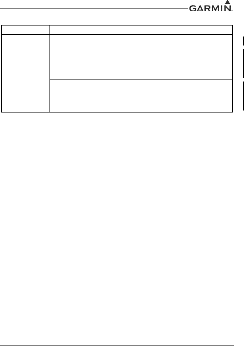
190-00303-05 GIA 63 Installation Manual
Rev. W Page 1-39
TSO-C169a 1. Garmin was granted a deviation from TSO-C169a paragraph 4.a.2 to allow the unit to be perma-
nently and legibly marked with a serial number and not the date of manufacture.
2. Garmin was granted a deviation from RTCA/DO-186B sections 2.4.8 and 2.5.8 to interpret Fluids
Susceptibility (RTCA/DO-160E, Section 11.0) testing as "When Required” in order to resolve a dis-
crepancy between guidance provided in RTCA/DO-186B, RTCA/DO-160E, EUROCAE ED-23B, and
EUROCAE ED-23C. A limitation must be provided in the installation manual stating that the appli-
ance must not be installed in areas where fluid contamination could be commonly encountered if this
category is not claimed in the unit environmental qualification form.
3. Garmin was granted a deviation from RTCA/DO-186B sections 2.4.7 to interpret Waterproofness
(RTCA/DO-160E, Section 10.0) testing as "When Required” in order to resolve a discrepancy
between guidance provided in RTCA/DO-186B, RTCA/DO-160E, EUROCAE ED-23B, and EURO-
CAE ED-23C. A limitation must be provided in the installation manual stating that the appliance
must not be installed in areas where water could be commonly encountered if this category is not
claimed in the unit environmental qualification form.
Table 1-19. GIA 63W with Enhanced COM TSO/ETSO Deviations
TSO/ETSO Deviation
DRAFT

GIA 63 Installation Manual 190-00303-05
Page 1-40 Rev. W
1.6.10 AFM/RFM/AFMS/RFMS/POH Considerations
Per TSO-C9c/ETSO-C9c deviation, the applicable AFM/RFM/AFMS/RFMS/POH shall list autopilot
engagement envelope for the certified aircraft.
Per TSO-C52b/ETSO-C52b deviation, the applicable AFM/RFM/AFMS/RFMS/POH shall state that the
system is not designed to perform unusual attitude recoveries from attitudes outside this range (as defined
in the TSO-C52b/ETSO-C52b deviation above). Ensure pilot operating guidance also states the FD
operating envelope.
1.6.10.1 GIA 63W and GIA 63H GPS Software Versions 2.40 or Earlier
Due to the equipment’s TSO qualified performance in tracking low-elevation-angle satellites, the
following limitations must be included in the Aircraft Flight Manual or Aircraft Flight Manual Supplement
for GIA63W or GIA 63H installations with GPS software version 2.40 or earlier, or in GIA 63W or
GIA 63H installations with antennas that require operational limitations (identified in Section 2.1.3.2):
This equipment does not comply with US 14 CFR Part 91, SFAR 97 requirements for
TSO-C145a/TSO-146a equipment when installed with certain models of GPS/WAAS
antennas identified in Section 2.1.3.2. Until complete compliance is demonstrated and
approved by the FAA, authorization to conduct any GPS or WAAS operation under
Instrument Flight Rules (IFR) requires that:
1. Aircraft using the GPS or WAAS capability of the GIA 63W or GIA 63H navigation equipment
under IFR must be equipped with an approved and operational alternate means of navigation
appropriate to the flight with the exception of oceanic and remote operations.
2. For flight planning purposes, if an alternate airport is required, it must have an approved
instrument approach procedure other than GPS or RNAV that is anticipated to be operational and
available at the estimated time of arrival. All equipment required for this procedure must be
installed and operational.
3. For flight planning purposes, Garmin Prediction Program 006-A0154-01 with the <insert installed
antenna part number> antenna selection should be used to confirm the availability of RAIM for
the intended flight in accordance with the local aviation authority guidelines for TSO-C129a
equipment. WAAS NOTAMs (or their absence) and generic prediction tools do not provide an
acceptable indication of the availability for the GIA 63W or GIA 63H equipment.
4. When flight planning an LNAV/VNAV or LPV approach, operators should use the Garmin
Prediction Program 006-A0154-01 with the <insert installed antenna part number> antenna
selection in addition to any NOTAMs issued for the approach.
The applicable AFM/RFM/AFMS/RFMS/POH shall also state the following instructions regarding the use
of the G1000 WFDE prediction program, which is required to be used for flight planning purposes for
Oceanic/Remote operations and when operating under the operational limitations listed above:
The G1000 WFDE prediction program works in combination with the Route Planning Software
(version 1.2 or later approved version). The route planning and WFDE prediction programs can be
downloaded from www.garmin.com. For information on using the WFDE prediction program, refer to
the WFDE Prediction Program Instructions Garmin part number 190-00643-01.
DRAFT

190-00303-05 GIA 63 Installation Manual
Rev. W Page 1-41
1.6.10.2 GIA 63W and GIA 63H GPS Software Versions 3.2 or Later
The following information may be used as guidance in developing an approved AFM, RFM, AFMS,
RFMS, and/or POH provided the system is installed in accordance with [AC 20-138C] and is comprised of
[two or more] [TSO-C145a Class 3 or TSO-C145c Class 3] approved Garmin GIA 63Ws or GIA 63Hs,
[two or more] [TSO-C146a Class 3 or TSO-C146c Class 3] approved Garmin GDU 1XXX Display Units,
Garmin-approved GPS/SBAS antennas (refer to Section 2.1.3.2), and GPS software version [3.2 or later
approved version]:
NOTE
Text contained in brackets “[ ]” is meant to serve as an example and will need to be
modified in order to reflect the actual installation.
GARMIN GNSS (GPS/SBAS) NAVIGATION SYSTEM EQUIPMENT APPROVALS
The Garmin GNSS navigation system is a GPS system with a Satellite Based Augmentation System
(SBAS) comprised of [two or more] [TSO-C145a Class 3 or TSO-C145c Class 3] approved Garmin GIA
63Ws or GIA 63Hs, [two or more] [TSO-C146a Class 3 or TSO-C146c Class 3] approved Garmin
GDU 1XXX Display Units, Garmin-approved GPS/SBAS antennas (refer to Section 2.1.3.2), and GPS
software version [3.2 or later approved version]. The Garmin GNSS navigation system in this aircraft is
installed in accordance with [AC 20-138C].
The Garmin GNSS navigation system as installed in this aircraft complies with the requirements of
[AC 20-138C] and has airworthiness approval for navigation using GPS and SBAS (within the coverage of
a Satellite Based Augmentation System complying with ICAO Annex 10) for IFR en route, terminal area,
and non-precision approach operations (including those approaches titled “GPS”, “or GPS”, and “RNAV
(GPS)” approaches). The Garmin GNSS navigation system is approved for approach procedures with
vertical guidance including “LPV” and “LNAV/VNAV”, within the U.S. National Airspace System.
The Garmin GNSS navigation system complies with the equipment requirements of AC 90-105 and meets
the equipment performance and functional requirements to conduct RNP terminal departure and arrival
procedures and RNP approach procedures without RF (radius to fix) legs. Part 91 subpart K, 121, 125, 129,
and 135 operators require operational approval from the FAA.
The Garmin GNSS navigation system complies with the equipment requirements of AC 90-100A for
RNAV 2 and RNAV 1 operations. In accordance with AC 90-100A, Part 91 operators (except subpart K)
following the aircraft and training guidance in AC 90-100A are authorized to fly RNAV 2 and RNAV 1
procedures. Part 91 subpart K, 121, 125, 129, and 135 operators require operational approval from the
FAA.
The Garmin GNSS navigation system has been found to comply with the requirements for GPS Class II
oceanic and remote navigation (RNP-10) without time limitations in accordance with [AC 20-138C] and
FAA Order [8400.12C]. The Garmin GNSS navigation system can be used without reliance on other long-
range navigation systems. This does not constitute an operational approval.
The Garmin GNSS navigation system has been found to comply with the navigation requirements for GPS
Class II oceanic and remote navigation (RNP-4) in accordance with [AC 20-138C] and FAA Order
8400.33. The Garmin GNSS navigation system can be used without reliance on other long-range
navigation systems. Additional equipment may be required to obtain operational approval to utilize RNP-4
performance. This does not constitute an operational approval.
DRAFT

GIA 63 Installation Manual 190-00303-05
Page 1-42 Rev. W
The Garmin GNSS navigation system complies with the accuracy, integrity, and continuity of function,
and contains the minimum system functions required for P-RNAV operations in accordance with JAA
Administrative & Guidance Material Section One: General Part 3: Temporary Guidance Leaflets, Leaflet
No 10 (JAA TGL-10 Rev 1). The GNSS navigation system has [two or more] [ETSO-C145 Class 3 or
ETSO-C145c Class 3 / TSO-C145a Class 3 or TSO-C145c Class 3] approved Garmin GIA 63Ws or
GIA 63Hs, and [two or more] [ETSO-146 Class 3 or ETSO-C146c Class 3 / TSO-C146a Class 3 or
TSO-C146c Class 3] approved Garmin GDU 1XXX Display Units. The Garmin GNSS navigation system
complies with the equipment requirements for P-RNAV and B-RNAV/RNAV 5 operations in accordance
with AC 90-96A CHG 1 and JAA TGL-10 Rev 1. This does not constitute an operational approval.
Garmin International holds an FAA Type 2 Letter of Acceptance (LOA) in accordance with [AC 20-153A]
for database integrity, quality, and database management practices for the Navigation database. Flight
crews and operators can view the LOA status at FlyGarmin.com then select “Type 2 LOA Status”.
Navigation information is referenced to WGS-84 reference system.
DRAFT

190-00303-05 GIA 63 Installation Manual
Rev. W Page 1-43
GARMIN GNSS (GPS/SBAS) NAVIGATION SYSTEM LIMITATIONS
The flight crew must confirm at system initialization that the Navigation database is current. Navigation
database is expected to be current for the duration of the flight. If the AIRAC cycle will change during
flight, the flight crew must ensure the accuracy of navigation data, including suitability of navigation
facilities used to define the routes and procedures for flight. If an amended chart affecting navigation data
is published for the procedure, the database must not be used to conduct the procedure.
GPS/SBAS based IFR en route, oceanic, and terminal navigation is prohibited unless the flight crew
verifies and uses a valid, compatible, and current Navigation database or verifies each waypoint for
accuracy by reference to current approved data.
Discrepancies that invalidate a procedure must be reported to Garmin International. The affected
procedure is prohibited from being flown using data from the Navigation database until a new Navigation
database is installed in the aircraft and verified that the discrepancy has been corrected. Navigation
database discrepancies can be reported at FlyGarmin.com then select “Aviation Data Error Report”. Flight
crew and operators can view Navigation data base alerts at FlyGarmin.com then select “NavData Alerts”.
For flight planning purposes, in areas where SBAS coverage is not available, the flight crew must check
RAIM availability. Within the United States, RAIM availability can be determined using the Garmin
WFDE Prediction program, [part number 006-A0154-01 (included in G1000 trainer software) version 3.00
or later approved version with GARMIN GA36 and GA37 antennas selected], or the FAA’s en route and
terminal RAIM prediction website: www.raimprediction.net, or by contacting a Flight Service Station.
Within Europe, RAIM availability can be determined using the Garmin WFDE Prediction program or
Europe’s AUGER GPS RAIM Prediction Tool at http://augur.ecacnav.com/augur/app/home. For other
areas, use the Garmin WFDE Prediction program. This requirement is not necessary if SBAS coverage is
confirmed to be available along the entire route of flight. The route planning and WFDE prediction
program may be downloaded from the Garmin website on the internet. For information on using the
WFDE Prediction Program, refer to Garmin WAAS FDE Prediction Program, part number 190-00643-01,
‘WFDE Prediction Program Instructions’.
For flight planning purposes, operations within the U.S. National Airspace System on RNP and RNAV
procedures when SBAS signals are not available, the availability of GPS RAIM shall be confirmed for the
intended route of flight. In the event of a predicted continuous loss of RAIM of more than five minutes for
any part of the intended route of flight, the flight should be delayed, canceled, or re-routed on a track where
RAIM requirements can be met.
For flight planning purposes for operations within European B-RNAV/RNAV-5 and P-RNAV airspace, if
more than one satellite is scheduled to be out of service, then the availability of GPS RAIM shall be
confirmed for the intended flight (route and time). In the event of a predicted continuous loss of RAIM of
more than five minutes for any part of the intended flight, the flight should be delayed, canceled, or
rerouted on a track where RAIM requirements can be met.
For flight planning purposes, operations where the route requires Class II navigation the aircraft’s operator
or flight crew must use the Garmin WFDE Prediction program to demonstrate that there are no outages on
the specified route that would prevent the Garmin GNSS navigation system from providing GPS Class II
navigation in oceanic and remote areas of operation that requires (RNP-10 or RNP-4) capability. If the
Garmin WFDE Prediction program indicates fault exclusion (FDE) is unavailable for more than 34
minutes in accordance with FAA Order 8400.12C for RNP-10 requirements, or 25 minutes in accordance
with FAA Order 8400.33 for RNP-4 requirements, then the operation must be rescheduled when FDE is
available.
DRAFT

GIA 63 Installation Manual 190-00303-05
Page 1-44 Rev. W
Both Garmin GPS navigation receivers must be operating and providing GPS navigation guidance to their
respective PFD for operations requiring RNP-4 performance.
North Atlantic (NAT) Minimum Navigational Performance Specifications (MNPS) Airspace operations
per AC 91-49 and AC 120-33 require both GPS/SBAS receivers to be operating and receiving usable
signals except for routes requiring only one Long Range Navigation sensor. Each display computes an
independent navigation solution based on the on-side GPS sensor. However, either display will
automatically revert to the cross-side sensor if the on-side sensor fails or if the cross-side sensor is
determined to be more accurate. [On G1000 installations a “BOTH ON GPS1” or “BOTH ON GPS2”
message does not necessarily mean that one GPS has failed. Refer to the MFD AUX-GPS STATUS page
to determine the state of the unused GPS].
Whenever possible, RNP and RNAV routes including Standard Instrument Departures (SIDs) and
Obstacle Departure Procedures (ODPs), Standard Terminal Arrival (STAR), and en route RNAV “Q” and
RNAV “T” routes should be loaded into the flight plan from the database in their entirety, rather than
loading route waypoints from the database into the flight plan individually. Selecting and inserting
individual named fixes from the database is permitted, provided all fixes along the published route to be
flown are inserted. Manual entry of waypoints using latitude/longitude or place/bearing is prohibited.
“GPS”, “or GPS”, and “RNAV (GPS)” instrument approaches using the Garmin navigation systems are
prohibited unless the flight crew verifies and uses the current Navigation database. GPS based instrument
approaches must be flown in accordance with an approved instrument approach procedure that is loaded
from the Navigation database.
Not all published Instrument Approach Procedures (IAP) are in the Navigation database. Flight crew
planning on flying an RNAV instrument approach must ensure that the Navigation database contains the
planned RNAV Instrument Approach Procedure and that approach procedure must be loaded from the
Navigation database into the FMS flight plan by its name.
IFR non-precision approach approval using the GPS/SBAS sensor is limited to published approaches
within the U.S. National Airspace System. Approaches to airports in other airspace are not approved unless
authorized by the appropriate governing authority.
The navigation equipment required to join and fly an instrument approach procedure is indicated by the
title of the procedure and notes on the IAP chart. Use of the Garmin GPS/SBAS receivers to provide
navigation guidance during the final approach segment of an ILS, LOC, LOC-BC, LDA, SDF, MLS or any
other type of approach not approved for “or GPS” navigation is prohibited. When using the Garmin VOR/
LOC/GS receivers to fly the final approach segment, VOR/LOC/GS navigation data must be selected and
presented on the CDI of the pilot flying.
Navigation information is referenced to WGS-84 reference system, and should only be used where the
Aeronautical Information Publication (including electronic data and aeronautical charts) conform to
WGS-84 or equivalent.
DRAFT

190-00303-05 GIA 63 Installation Manual
Rev. W Page 1-45
1.6.11 Other Regulatory Criteria (GIA 63)
RTCA/DO-178B Level B, C, D (Software)
EUROCAE ED 12B (Software)
RTCA/DO-160D (Environmental Conditions)
EUROCAE ED 14D (Environmental Conditions)
RTCA/DO-161A (Airborne Ground Proximity Warning Equipment)
RTCA/DO-208 Class A1 (GPS)
RTCA/DO-186a Class 3 and 5 (VHF Com Transmitter)
RTCA/DO-186a Class C and E (VHF Com Receiver)
RTCA/DO-196 (VOR Receiver)
RTCA/DO-195 Class A (Localizer Receiver)
RTCA/DO-192 (Glideslope Receiver)
ICAO Annex 10 Volume III, EUROCAE ED-23B (VHF Com Transceiver)
ICAO Annex 10 Volume I, EUROCAE ED-22B (VOR Receiver)
ICAO Annex 10 Volume I, EUROCAE ED-46B (Localizer Receiver)
EUROCAE ED-47B (Glideslope Receiver)
EUROCAE ED-72A (GPS)
SAE AS 402B (Automatic Pilots)
SAE AS 8008 (Flight Director Equipment)
DRAFT

GIA 63 Installation Manual 190-00303-05
Page 1-46 Rev. W
1.6.12 Other Regulatory Criteria (GIA 63W and GIA 63H)
All 011-01105-XX part numbers:
RTCA/DO-178B Level A*, B, C, D (Software)
EUROCAE ED 12B (Software)
RTCA/DO-160E (Environmental Conditions)
EUROCAE ED 14E (Environmental Conditions)
RTCA/DO-161A (Airborne Ground Proximity Warning Equipment)
RTCA/DO-196 (VOR Receiver)
RTCA/DO-195 Class A (Localizer Receiver)
RTCA/DO-192 (Glideslope Receiver)
ICAO Annex 10 Volume I, EUROCAE ED-22B (VOR Receiver)
ICAO Annex 10 Volume I, EUROCAE ED-46B (Localizer Receiver)
EUROCAE ED-47B (Glideslope Receiver)
SAE AS 402B (Automatic Pilots)
SAE AS 8008 (Flight Director Equipment)
*RTCA/DO-178B Level A is only supported through use of GIA software part numbers 006-B0544-3( ) and later. All other GIA software part numbers support RTCA/
DO-178B Levels B, C and D only.
011-01105-0X only:
RTCA/DO-254 Level A and C (CLD devices)
RTCA/DO-229c Class Beta 3 (GPS/WAAS)
RTCA/DO-186a Class 3 and 5 (VHF Com Transmitter)
RTCA/DO-186a Class C and E (VHF Com Receiver)
ICAO Annex 10 Volume III, EUROCAE ED-23B (VHF Com Transceiver)
011-01105-2X and 011-01105-3X only:
RTCA/DO-254 Level A (CLD devices)
RTCA/DO-229c Class Beta 3 (GPS/WAAS)
RTCA/DO-186b Class 3 and 5 (Vin @ 28VDC) (VHF Com Transmitter)
Class 4 and 6(Vin @ 14VDC) (VHF Com Transmitter)
RTCA/DO-186b Class C and E (VHF Com Receiver)
ICAO Annex 10 Volume III, EUROCAE ED-23B (VHF Com Transceiver)
011-01105-4X only:
RTCA/DO-254 Level A (CLD devices)
RTCA/DO-229d Class Beta 3 (GPS/WAAS)
RTCA/DO-186b Class 3 and 5 (VHF Com Transmitter)
RTCA/DO-186b Class C and E (VHF Com Receiver)
ICAO Annex 10 Volume III, EUROCAE ED-23C (VHF Com Transceiver)
RTCA/DO-281a (VDL Mode 2)
RTCA/DO-224b (VHF Digital Data)
DRAFT
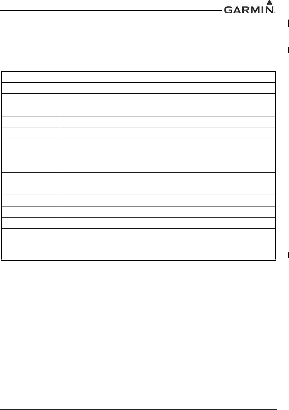
190-00303-05 GIA 63 Installation Manual
Rev. W Page 1-47
1.7 Reference Documents
The following publications are sources of additional information for installing the GIA 63(X). Before
installing the GIA 63(X), the technician should read all relevant referenced materials along with this
manual.
Table 1-20. GIA 63(X) Reference Documents
Part Number Document
190-00303-00 G1000 System Installation Manual
190-00303-04 G1000 Line Maintenance and Configuration Manual
560-5047-00 Apollo A-34 GPS Antenna Installation Manual
II A258002 Comant CI 2580-410 Installation Instructions
II A258005 Comant CI 2580-200 Installation Instructions
II A42803 Comant CI 428-410 Installation Instructions
II A42809 Comant CI 428-200 Installation Instructions
II A272803 Comant CI 2728-410 Installation Instructions
II A272806 Comant CI 2728-200 Installation Instructions
190-00848-00 GA 35, GA 36, and GA 37 Antenna Installation Instructions
190-00355-02* GDL 69/69A Installation Manual
190-00522-01 GA 55A, GA 56A, GA 57 Installation Instructions
190-00483-01 GA 56W Antenna Installation Instructions
004-00287-00 Antenna Minimum Performance Specification
for Garmin’s GPS/WAAS Receiver System
190-00303-24 GDR 66 Installation Manual
*GA 55 technical specifications and antenna performance is contained in the GDL 69/69A Installation
Manual.
DRAFT

GIA 63 Installation Manual 190-00303-05
Page 1-48 Rev. W
This page intentionally left blank
DRAFT
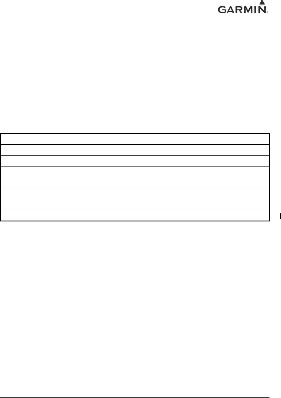
190-00303-05 GIA 63 Installation Manual
Rev. W Page 2-1
2 INSTALLATION OVERVIEW
2.1 Introduction
This section provides hardware equipment information for installing the GIA 63(X), related hardware, and
antennas. Installation of the GIA 63(X) should follow the aircraft TC or STC requirements. Cabling is
fabricated by the installing agency to fit each particular aircraft. The guidance of FAA advisory circulars
AC 43.13-1B and AC 43.13-2B, where applicable, may be found useful for making retro-fit installations
that comply with FAA regulations. Refer to the G1000 System Installation Manual, Garmin part number
190-00303-00 for further details on the mechanical aspects. For installation in an aircraft using the remote
mounted standalone rack, refer to Appendix B for rack drawings and dimensions.
2.1.1 Unit Configurations
The GIA 63(X) is only available as a single unit under the following part numbers.
Table 2-1. GIA 63(X) Part Numbers
Item Garmin P/N
GIA 63 Unit Only, (011-00781-00) 010-00335-00
GIA 63 ETSO Unit Only, (011-00781-01) 010-00335-10
GIA 63W Unit Only, (011-01105-00) 010-00386-00
GIA 63W A2/B2 Audio Lightning Unit Only (011-01105-01) 010-00386-10
GIA 63W Updated NAV/COM (011-01105-20) 010-00386-20
GIA 63H (011-01105-30)* 010-00386-30
GIA 63W with Enhanced COM (011-01105-40) 010-00386-40
*Only the 010-00386-30 GIA 63H unit together with the 011-02425-00 Rack & 011-00963-01 Back Plate is approved for DO-160F,
Category U, Curve G vibration levels.
DRAFT
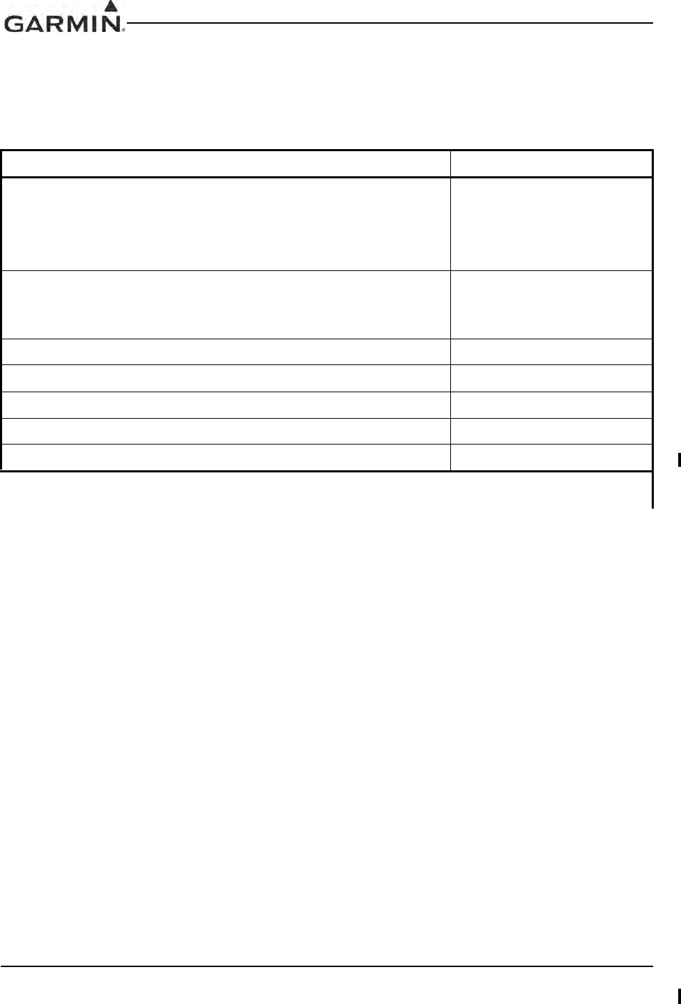
GIA 63 Installation Manual 190-00303-05
Page 2-2 Rev. V
2.1.2 Required Accessories
Each of the following accessories is provided separately from the GIA 63(X). Either rack (modular,
standalone, or helicopter) and reminder of the accessories are required for installation.
Table 2-2. Required Accessories
Item Garmin P/N
GIA 63(W) Modular Install Rack
or
GIA 63(W) Standalone Install Rack
or
GIA 63H Helicopter Install Rack*
115-00426-00
115-01239-00
011-02425-00
G1000 Rack Nutplate Kit (Modular Rack Only)
011-00915-01 (preferred)
or
011-01148-01
GIA 63(W) Back Plate (Modular and Standalone) 011-00963-00
GIA 63H Back Plate (Helicopter)* 011-00963-01
GIA 63(X) Connector Kit w/ Spider 011-01000-00
GIA 63(X) Connector Kit w/ Shield Block* 011-01000-01
GIA 63(X) Connector Kit, IF Seal 011-01000-03
*Only the 010-00386-30 GIA 63H unit together with the 011-02425-00 Rack , 011-00963-01 Back Plate, and 011-01000-01 Con-
nector Kit is approved for DO-160F, Category U, Curve G vibration levels.
DRAFT

190-00303-05 GIA 63 Installation Manual
Rev. W Page 2-3
2.1.3 Additional Equipment Required
The following installation accessories are required but not provided:
COM Antenna: Shall meet TSO-C169()*, or shall meet both TSO-C37() and C38(),
Broad band, 50 Ω, vertically polarized with coaxial cable
GPS Antenna: GIA 63 (011-00781-0X) shall meet TSO-C129a. TSO-C144 antennas can also
meet TSO-C129a requirements for the GIA 63 (Refer to Section 2.1.3.1).
GIA 63H and GIA 63W (011-01105-0X/-2X/-3X) shall meet TSO-C144 and
additional system requirements specified by TSO-C145a. Refer to Section 2.1.3.2 for
approved antennas
GIA 63W (011-01105-4X) shall meet TSO-C144 and additional system requirements
specified by TSO-C145c. Refer to Section 2.1.3.2 for approved antennas
VOR/LOC Antenna: Shall meet TSO-C40() and C36(). Broad band, 50 Ω, horizontally polarized
with coaxial cable
Glideslope Antenna: Shall meet TSO-C34(). Broad band, 50 Ω, horizontally polarized with coaxial
cable or low-loss splitter used with the VOR/LOC antenna
Headphones: 500 Ω nominal impedance Microphone: Low impedance, carbon or dynamic,
with transistorized pre-amp
Hardware: #6-32 x 100°Flathead SS Screw [(MS24693, AN507R or other approved
fastener) (4 ea.)] for horizontal mounting of the standalone rack.
Hardware: #8-32 Panhead Machine Screw [(MS35206, AN526 or other approved
fastener) (4 ea.)] for vertical mounting of the standalone rack.
Hardware: #10-32 x 100°Flathead Screw [(MS24694S51 or screw of same or greater strength)(4
ea.)] for mounting of the helicopter rack.
*GIA 63W and GIA 63H only
2.1.3.1 Required Antenna for the GIA 63
Antennas used with the GIA 63 (non-WAAS) must meet the antenna specifications shown in Section 2.6.
In addition, TSO-C144 antennas can also meet TSO-C129a requirements for the GIA 63 (non-WAAS) if
their additional gain (which is about 16dB at 1.5 GHz for antennas produced by Garmin) is offset by added
attenuation in-line with the GIA 63 (non-WAAS). If an in-line attenuator is used, it must pass DC current
(40 mA max at 4.6 VDC) which is provided from the GPS receiver to the antenna pre-amplifier.
2.1.3.2 Required WAAS Antennas for the GIA 63W and GIA 63H
The following is a list of TSO-C144 antennas that allow the GIA 63W and GIA 63H with GPS software
version 3.2 or later to meet TSO-C145a requirements without requiring the operational limitations
specified in Section 1.6.10.2 of this manual:
DRAFT
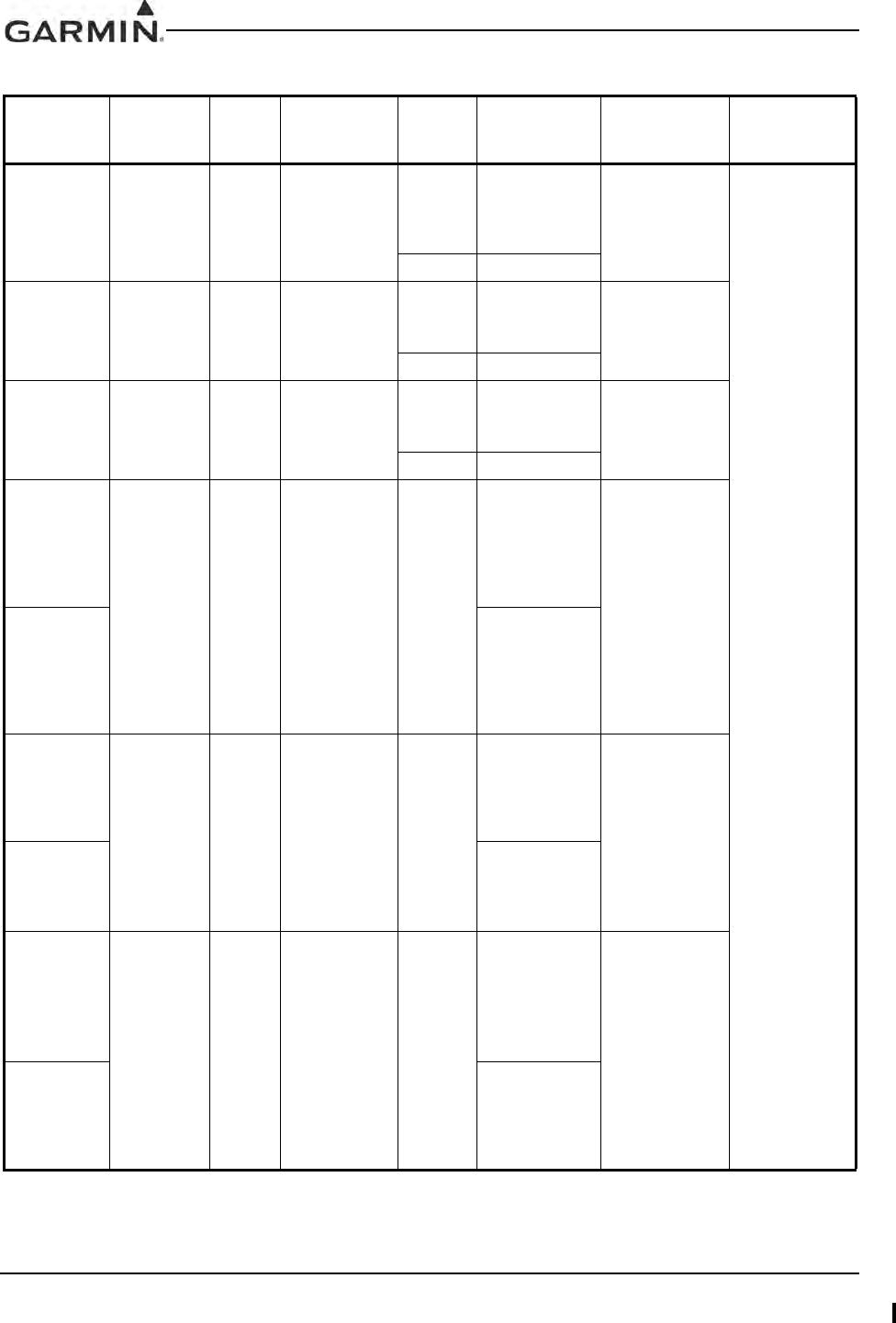
GIA 63 Installation Manual 190-00303-05
Page 2-4 Rev. V
Table 2-3. TSO-C145a WAAS Antennas for the GIA 63W and GIA 63H
Model Mount
Style Conn
Type
SATCOM
Compatible
[3] Mfr Antenna Part
Number Garmin Order
Number Additional
Requirements
GA 35 GPS
WAAS
Antenna [6]
Screw
Mount,
Teardrop
Footprint [2]
TNC Yes
Aero
Antenna
AT575-
93GWTNCF-
000-
RG-27-NM 013-00235-00
None
Garmin 013-00235-00
GA 36 GPS
WAAS
Antenna [6]
Screw
Mount,
ARINC 743
Footprint
TNC Yes
Aero
Antenna
AT575-
326GW-TNCF-
000-RG-27-NM 013-00244-00
Garmin 013-00244-00
GA 37
FIS/WAAS
Antenna [6]
Screw
Mount,
ARINC 743
Footprint
TNC Yes
Aero
Antenna
AT2300-
126GW-TNCF-
000-RG-27-NM 013-00245-00
Garmin 013-00245-00
Comant
2580-200
WAAS and
COM
Antenna
[6] [8]
Screw
Mount,
Teardrop
Footprint [2]
BNC
TNC
[5]
Yes Comant
CI 2580-200
N/A
Comant
2580-410
FIS/WAAS
/COM
Antenna[6]
[8]
CI 2580-410
Comant
428-200
WAAS
Antenna
[6] [8]
Screw
Mount,
ARINC 743
Footprint
TNC Yes Comant
CI 428-200
N/A
Comant
428-410
FIS/WAAS
Antenna[6][8]
CI 428-410
Comant
2728-200
WAAS and
COM
Antenna
[6][8]
Screw
Mount,
Teardrop
Footprint [7]
BNC
TNC
[5]
Yes Comant
CI 2728-200
N/A
Comant
2728-410
FIS/WAAS
/COM
Antenna[6][8]
CI 2728-410
DRAFT
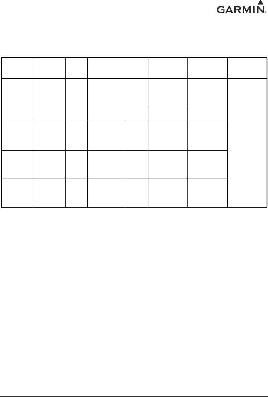
190-00303-05 GIA 63 Installation Manual
Rev. W Page 2-5
The following is a list of known TSO-C144 antennas that allow the GIA 63W and GIA 63H with any
version of GPS software version to meet TSO-C145a requirements with the operational limitations
specified in Section 1.6.4 and 1.6.7 of this manual:
[1] Same footprint and mounting hole pattern as GA 56.
[2] Same mounting hole pattern as the GA 56, but has a physically larger footprint.
[3] SATCOM compatibility requirements are as specified by RTCA/DO-229C Section 2.5.6.1,
Section 2.5.8.2, Appendix C.2.1, and Appendix C.2.2.
[4] The WAAS GPS antenna connector is a BNC type. The XM antenna connector is a TNC type.
[5] The WAAS GPS antenna connector (and XM antenna connector where applicable) is TNC type.
The VHF COM antenna connector is BNC type.
[6] Not approved for use with the GIA 63 (non-WAAS) since max DC current specification exceeds
40 mA.
[7] Larger footprint and mounting hole pattern than GA 56, GA 35 or CI 2580.
[8] It is the installer’s responsibility to ensure the antenna complies with Antenna Minimum
Performance Specification for Garmin’s GPS/WAAS Receiver System Antenna
(004-00287-00) by communicating the requirement to the supplier and obtaining a certificate of
compliance to 004-00287-00 from the supplier. An antenna that complies only with
TSO-C144 requirements is not adequate for this installation.
Other TSO-C144 antennas may meet the installation requirements of the GIA 63W and GIA 63H. Contact
Garmin to ensure compatibility and applicable operation limitations before beginning the installation.
Table 2-4. TSO-C144 WAAS Antennas for the GIA 63W and GIA 63H
Model Mount
Style Conn
Type
SATCOM
Compatible
[3] Mfr Antenna Part
Number Garmin Order
Number Additional
Requirements
A-34 GPS
WAAS
Antenna
Screw
Mount,
Teardrop
Footprint [2]
TNC Yes
Aero
Antenna
AT575-
93WTNCF-
000-05-
26-NM 013-00113-00
The operational
limitation
described in
Section 1.6.4
and 1.6.7
requires use of
006-A0154-01
as the Predic-
tion
Program in
conjunction with
these antennas.
Garmin
AT 590-1112
GA56A GPS
WAAS
Antenna
Screw
Mount,
ARINC 743
Footprint
BNC No Garmin 011-01154-00 010-10599-00
GA56W
GPS
WAAS
Antenna
Stud
Mount,
Teardrop
Footprint [1]
BNC No Garmin 011-01111-00 010-10561-01
GA57 GPS
WAAS and
FIS
Antenna
Screw
Mount,
ARINC 743
Footprint
BNC
TNC
[4]
No Garmin 011-01032-00 010-10604-00
DRAFT

GIA 63 Installation Manual 190-00303-05
Page 2-6 Rev. V
2.2 Installation Considerations
The GIA 63(X) interfaces with the G1000 system and with various avionics equipment. Fabrication of a
wiring harness is required. Sound mechanical and electrical methods and practices are required for
installation of the GIA 63(X).
2.2.1 Antenna Considerations
Antenna installations on pressurized cabin aircraft require FAA approved installation design and
engineering substantiation data whenever such antenna installations incorporate alteration (penetration) of
the cabin pressure vessel by connector holes and/or mounting arrangements. For needed engineering
support pertaining to the design and approval of such pressurized aircraft antenna installations, it is
recommended that the installer proceed according to any of the following listed alternatives:
1. Obtain approved antenna installation design data from the aircraft manufacturer.
2. Obtain an FAA approved STC, pertaining to, and valid for the antenna installation.
3. Contact the FAA Aircraft Certification Office in the appropriate Region and request identification
of FAA Designated Engineering Representatives (DERs) who are authorized to prepare and
approve the required antenna installation engineering data.
4. Locate an appropriate consultant FAA DER by reviewing the “FAA Consultant DER Directory”,
which can be found at the FAA “Designee and Delegation” web page.
5. Contact an aviation industry organization such as the Aircraft Electronics Association for
assistance.
2.2.2 GPS Antenna Location
The GPS antenna is a key element in the overall system performance and integrity for a GPS/WAAS
navigation system. The mounting location, geometry, and surroundings of the antenna can affect the
system performance and/or availability. The following guidance provides information to aid the installer in
ensuring that the most optimum location is selected for the installation of the GPS antenna. The installation
guidelines presented here meet the intent of AC 20-138A section 16. The greater the variance from these
guidelines, the greater the chance of decreased availability. Approach procedures with vertical guidance
are the most sensitive to these effects. LNAV only approaches, terminal operations, and enroute operations
may also be affected. Because meeting all of these installations guidelines may not be possible on all
aircraft, these guidelines are listed in order of importance to achieve optimum performance. Items 4 below
are of equal importance and their significance may depend on the aircraft installation. The installer should
use their best judgment to balance the installation guidelines.
DRAFT

190-00303-05 GIA 63 Installation Manual
Rev. W Page 2-7
For rotorcraft, locate the GPS antenna as far as possible from the main rotor hub. This reduces the
percentage of time the blade blocks the antenna. Also mount it as far below the blade surface as possible if
installing the antenna under the blade. This reduces signal distortion caused by the blades.
1. Mount the antenna as close to level as possible with respect to the normal cruise flight attitude of
the aircraft. If the normal flight attitude is not known, substitute the waterline, which is typically
referenced as level while performing a weight and balance check.
2. The GPS antenna should be mounted in a location to minimize the effects of airframe shadowing
during typical maneuvers. Typically mounting farther away from the tail section reduces signal
blockage seen by the GPS antenna.
3. The GPS antenna should ideally be located at the opposite end of the aircraft from the COM unit in
order to make the GPS less vulnerable to harmonics radiated from the COM itself.
4. The GPS antenna should be mounted no closer than two feet (edge to edge) and ideally three feet
from any VHF COM antenna or any other antenna which may emit harmonic (or other) interfer-
ence at the L1 frequency of 1575.42 MHz. An aircraft EMC check (reference VHF COM interfer-
ence check in Post Installation Checkout procedures) can verify the degradation of GPS in the
presence of interference signals. If an EMC check reveals unacceptable interference, insert a GPS
notch filter in line with the offending VHF COM or the (re-radiating) ELT transmitter.
NOTE
The separation requirement does not apply to GPS and COM combination antennas,
provided the antenna model is TSO authorized and has been tested to meet Garmin’s
minimum performance standards. The separating requirement includes the combination
with an XM antenna element as well.
The GPS antenna should be mounted no closer than two feet (edge to edge) and ideally
three feet from any antennas emitting more than 25 watts of power. An aircraft EMC check
can verify the degradation of GPS in the presence of interference signals.
To minimize the effects of shadowing at 5° elevation angles, the GPS antenna should be
mounted no closer than 6 inches (edge to edge) from other antennas, including passive
antennas such as another GPS antenna or XM antenna.
5. To maintain a constant gain pattern and limit degradation by the windscreen, avoid mounting the
antenna closer than 3 inches from the windscreen.
6. For multiple GPS installations, the antennas should not be mounted in a straight line from the front
to the rear of the fuselage. Also varying the mounting location will help minimize any aircraft
shading by the wings or tail section (in a particular azimuth, when one antenna is blocked the other
antenna may have a clear view).
DRAFT
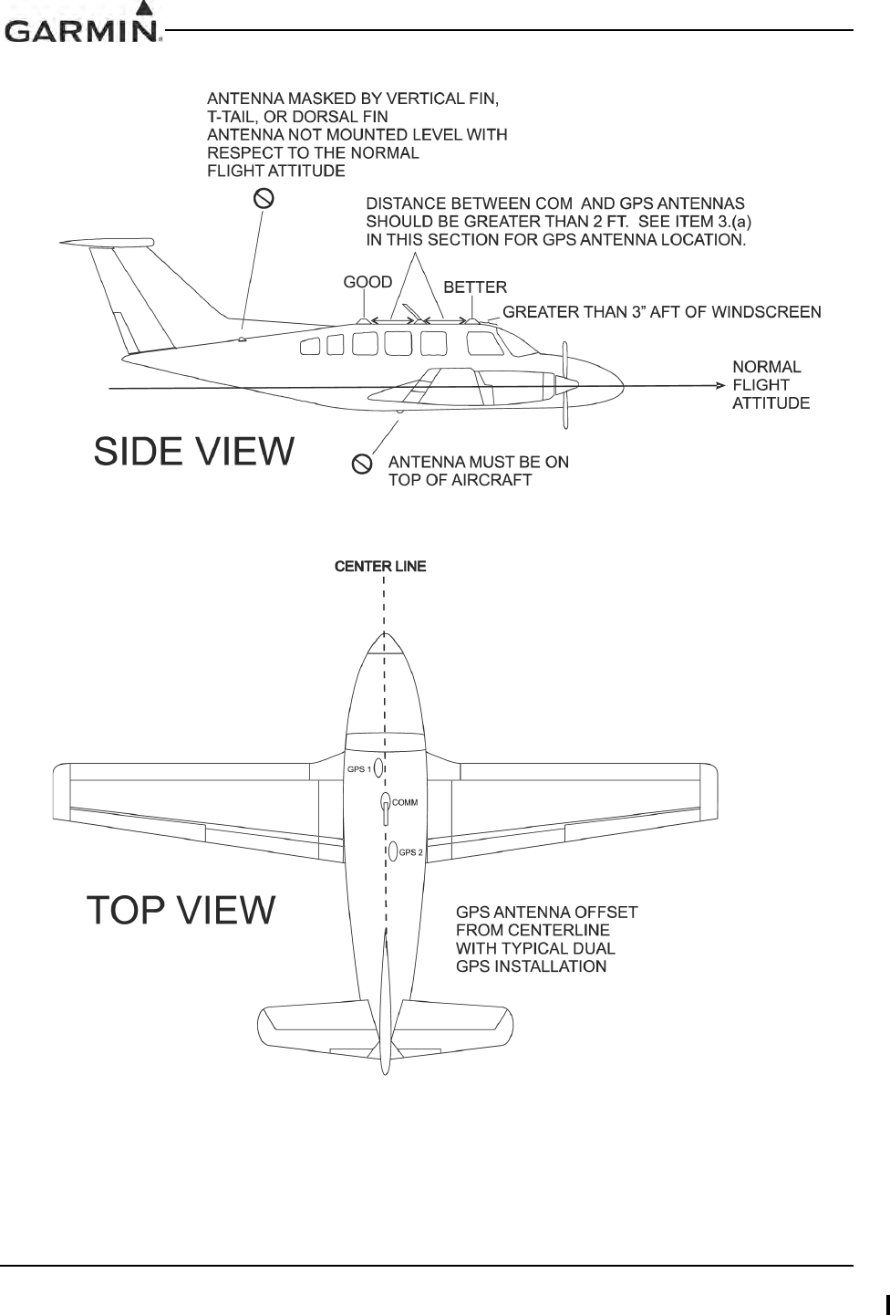
GIA 63 Installation Manual 190-00303-05
Page 2-8 Rev. V
Figure 2-1 shows the recommended placement of antennas.
Figure 2-1. GPS Antenna Considerations
DRAFT

190-00303-05 GIA 63 Installation Manual
Rev. W Page 2-9
2.2.3 Com Antenna Location
The GIA 63(X) COM antenna should be well removed from all projections, engines and propellers. The
ground plane surface directly below the antenna should be a flat plane over as large an area as possible (18
inches square, minimum). The antenna should be mounted a minimum of six feet from any DME or other
COM antennas, four feet from any ADF sense antennas, three feet from the GIA 63(X) and its GPS
antenna, and as far as practical from any ELT antennas.
If simultaneous use of two or more COM transceivers is desired, the COM antennas must be spaced for
maximum isolation. For a two COM installation, one COM antenna should be mounted on the top of the
fuselage and the other antenna should be mounted on the bottom of the fuselage. For installations with
three COM’s, one COM antenna should be mounted on the top of the fuselage and the other two antennas
should be mounted on the bottom of the fuselage and physically separated from each other as much as
possible.
Simultaneous COM performance varies significantly across installations and is affected by both the
isolation between the COM antennas and the separation of the tuned frequencies. Each installation should
be individually examined to determine the expected performance of simultaneous COM.
2.2.4 VOR/LOC Antenna Location
The GIA 63(X) VOR/LOC antenna should be well removed from all projections, engines and propellers. It
should have a clear line of sight if possible. The antenna must be mounted along the centerline of the
aircraft, minimizing the lateral offset.
2.2.5 Glideslope Antenna Location
The GIA 63(X) Glideslope antenna should be well removed from all projections, engines and propellers. It
should have a clear line of sight if possible.
2.2.6 Electrical Bonding
No special precautions need to be taken to provide a bonding path between the GPS antenna and the
aircraft structure. Follow the manufacturers’ instructions for the COM, VOR/LOC and Glideslope
antennas.
2.2.7 VHF COM/GPS Interference
On some installation VHF COM transceivers, Emergency Locator Transmitter (ELT) antennas, and
Direction Finder (DF) receiver antennas can re-radiate through the GPS antenna. The GIA 63(X) COM
does not interfere with its own GPS section. However, placement of the GA 56 GPS antenna (or other
comparable antenna) relative to a COM transceiver and COM antenna (including the GIA 63(X) COM
antenna), ELT antenna, and DF receiver antenna is critical.
Use the following guidelines, in addition to others in this document, when locating the GIA 63(X) and its
antennas.
• GPS Antenna—Locate as far as possible from all COM antennas and all COM transceivers
(including the GIA 63(X) COM), ELT antennas, and DF antennas. The GPS antenna is less
susceptible to harmonic interference if a 1.57542 GHz notch filter is installed on the COM trans-
ceiver antenna output.
• Locate the GIA 63(X) as far as possible from all COM antennas.
DRAFT

GIA 63 Installation Manual 190-00303-05
Page 2-10 Rev. V
If a COM antenna is found to be the problem, a 1.57542 GHz notch filter (Garmin P/N 330-00067-00) may
be installed in the VHF COM coax, as close to the COM as possible. This filter is not required for the
GIA 63(X) transmitter.
If a COM is found to be radiating, the following can be done:
1. Replace or clean the VHF COM rack connector to ensure good coax ground.
2. Place grounding straps between the GIA 63(X) unit, VHF COM and a good ground.
3. Shield the VHF COM wiring harness.
2.3 Rack Considerations
A location away from heating vents or other sources of heat generation is optimal. The GIA 63(W) can be
mounted using the G1000 system rack. The unit may be mounted remotely if desired. The GIA 63H must
be mounted in the Helicopter Rack.
DRAFT

190-00303-05 GIA 63 Installation Manual
Rev. W Page 2-11
2.4 Cabling and Wiring
Refer to the interconnect examples in Appendix C for wire gauge guidance.
In some cases, a larger gauge wire such as AWG #16, #18, or #20 may be needed for power connections.
Special thin-wall heat shrink tubing is also provided to insulate the extended barrels inside the backshell. If
using AWG #16 or #18 barrel contacts, ensure that no two contacts are mounted directly adjacent to each
other. This minimizes the risk of contacts touching and shorting to adjacent pins and to ground.
Ensure that routing of the wiring does not come in contact with sources of heat, RF or EMI interference.
Check that there is ample space for the cabling and mating connectors. Avoid sharp bends in cabling and
routing near aircraft control cables.
Coaxial cable with 50 Ω nominal impedance and meeting applicable aviation regulations should be used
for the installation. A typical maximum cable length for the GPS antenna is 40 feet. The installer shall
insure that the attenuation does not exceed 10 dB at 1.5 GHz for the GIA 63, and falls between 3 dB and
7 dB inclusive at 1.5 GHz for the GIA 63W or GIA 63H.
Check that there is ample space for the cabling and mating connectors. Avoid sharp bends in cabling,
particularly the COM antenna cable, and routing near aircraft control cables. Cabling for the GIA 63(X)
should not be routed near components or cabling which are sources of electrical noise. Do not route the
COM antenna coax near any ADF antenna cables. Route the GPS, VOR/LOC, and Glideslope antenna
cables as far as possible away from all COM transceivers and antenna cables.
2.5 Cooling Air
The GIA 63(X) meets all TSO requirements without external cooling. However, as with all electronic
equipment, lower operating temperatures extend equipment life. On the average, reducing the operating
temperature by 15-20 °C (25 to 35 °F) doubles the mean time between failure (MTBF). Recommended
airflow rating is 1 CFM (cubic foot per minute) at a pressure equivalent to 0.1 inches of water. Potential
damage to your GIA 63(X) may occur by using outside forced air to cool the equipment. Therefore, it is
recommended that an electric forced air fan be installed, of the indicated rating, to cool this equipment.
Units tightly packed in the avionics stack heat each other through radiation, convection, and sometimes by
direct conduction. Even a single unit operates at a much higher temperature in still air than in moving air.
Fans or some other means of moving the air around electronic equipment are usually a worthwhile
investment. A 5/8” diameter air fitting is provided on the rear of the mounting rack for the purpose of
admitting cooling air under such conditions. If a form of forced air cooling is installed, make certain that
rainwater cannot enter and be sprayed on the equipment. Refer to the G1000 System Installation manual,
Garmin part number 190-00303-00, for information on cooling requirements.
DRAFT

GIA 63 Installation Manual 190-00303-05
Page 2-12 Rev. V
2.6 GIA 63 Minimum Installation Requirements
Below is a list of required devices for TSO-C129a category A1 certification.
Pressure Altitude Device
This device delivers pressure altitude data to the GIA 63. This data comes from the Garmin GDC 74A Air
Data Computer.
Manual Course Device
This device delivers the manual course select to the GIA 63, which is required for the VOR receiver, and
optional for the GPS receiver. Course information can come from an analog resolver, or from the GDU
PFD/MFD via Ethernet HSDB.
HSI/CDI Indicator or GDU
This device displays Nav Flag, Left/Right, To/From, Glideslope Flag, and Up/Down.
Qualified GPS Antenna
This antenna must meet the following requirements:
1. DO-160C Environmental Conditions
The antenna shall meet the environmental conditions listed below and shall conform to the test
requirements of RTCA DO-160C.
Environmental Condition Category Description
Temperature (operating) F2 -55 to +70°C
(ground survival) F2 -55 to +85°C
Altitude F2 55,000 feet
Temperature Variation A10oC per minute
Humidity C95% at +55°C
Vibration CLMY Turbo/
Reciprocating/
Helicopter
Waterproofness SContinuous
Stream
Fluids FDeicing Fluid
Lightning 2A Direct Effects
Icing C0.15” thick
DRAFT

190-00303-05 GIA 63 Installation Manual
Rev. W Page 2-13
2. Electrical Characteristics
LNA Supply voltage 4.5 ± 0.5 VDC
LNA Supply Current 20 mA Maximum
LNA Operating Frequency 1575.42 ± 2.00 MHz
LNA Gain 20 dB Maximum, 12dB Minimum
LNA Noise Figure 3.0 dB Maximum
LNA Output VSWR (50 Ω) 2:1 Maximum
LNA Input power at -1 dB Gain Compression -6 dB Minimum
LNA Bandwidth
(-3 dB) 40 MHz Maximum
(-20 dB) 100 MHz Maximum
(-40 dB) 250 MHz Maximum
3. Radiation Characteristics
Polarization RHCP
Operating Frequency 1575.42 ± 2.00 MHz
Gain (on axis) 2.0 dBic Minimum
(at 160° beam width) -6.0 dBic Minimum
Cross Pole Gain (LHCP)
(on axis) -8 dBic Maximum
(at 160° beam width) -9 dBic Maximum
4. Mounting Requirements
Cable connection BNC Female
Mounting studs Four 8-32 UNC-2A studs 0.50” long
2.7 GIA 63W and GIA 63H Minimum Installation Requirements
Below is a list of required devices for TSO-C145a Class 3 or TSO-C145c Class 3 certification.
Manual Course Device
This device delivers the manual course select to the GIA 63W or GIA 63H, which is required for the VOR
receiver, and optional for the GPS receiver. Course information can come from an analog resolver, or from
the GDU PFD/MFD via Ethernet HSDB.
GDU PFD/MFD
This device displays Nav Flag, Left/Right, To/From, Glideslope Flag, and Up/Down as well as integrity
messages. In addition it provides manual course selection to the GIA, which is required for the VOR
receiver and optional for the GPS receiver.
Qualified GPS Antenna
Refer to Section 2.1.3.2 for a list of approved antennas.
DRAFT
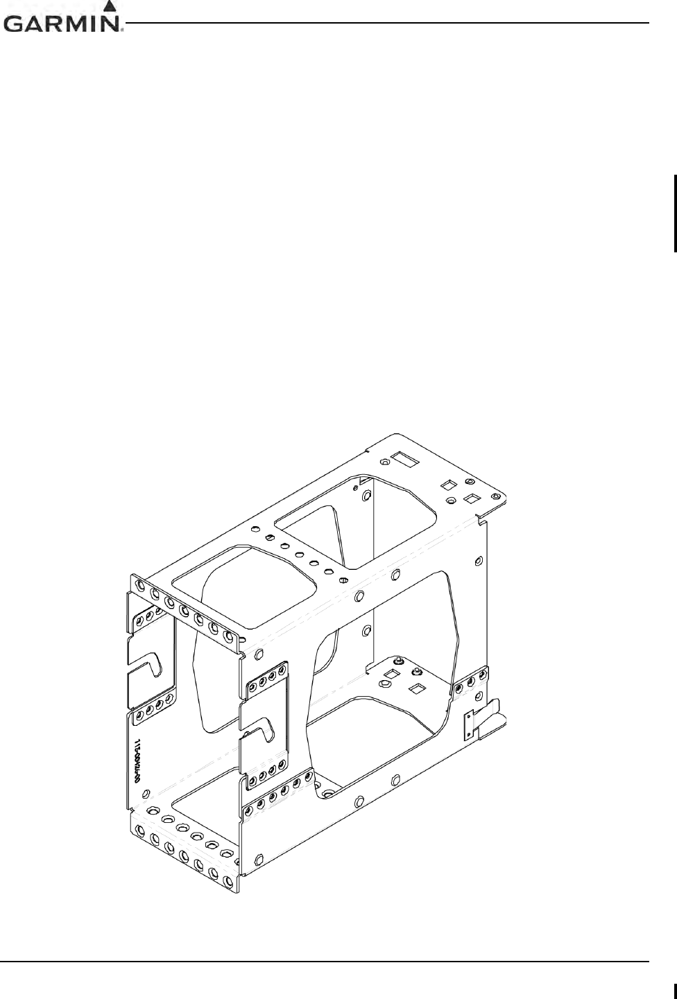
GIA 63 Installation Manual 190-00303-05
Page 2-14 Rev. V
2.8 Mounting Requirements
The GIA 63(X) mounting surface must be capable of providing structural support and electrical bond to the
aircraft to minimize radiated EMI and provide protection from High-Intensity Radiation Fields (HIRF).
The GIA 63(W) can be mounted using the G1000 modular system rack, or may be mounted remotely using
the Standalone rack. The GIA 63H must be mounted in the Helicopter Rack. Refer to drawings in
Appendix B.
2.8.1 Mounting Limitations
The GIA 63(X) shall not be mounted in a location where either fluid contamination or water is commonly
encountered unless the applicable unit EQF indicates that the unit has claimed the appropriate RTCA DO-
160 categories for these environments.
2.8.2 Modular Rack Considerations
Figure 2-2 and Figure B-2 show the GIA 63(W) G1000 modular rack. The modular rack is fastened to the
main system rack using the nutplate kit listed in Section 2.1.2. Refer to Figure B-2 for nutplate placement
locations. Figure B-1 gives the GIA 63(W) modular rack dimensions.
The unit may also be mounted outside of the G1000 system rack. The number and positions of screws
noted in Figure B-2 are to be used when mounting the GIA 63(W) modular rack outside of the G1000
system rack. Aircraft manufacturer must fabricate any additional mounting equipment needed, use outline
and installation drawings in Appendix B for reference.
Figure 2-2. GIA 63(W) Modular Rack
DRAFT
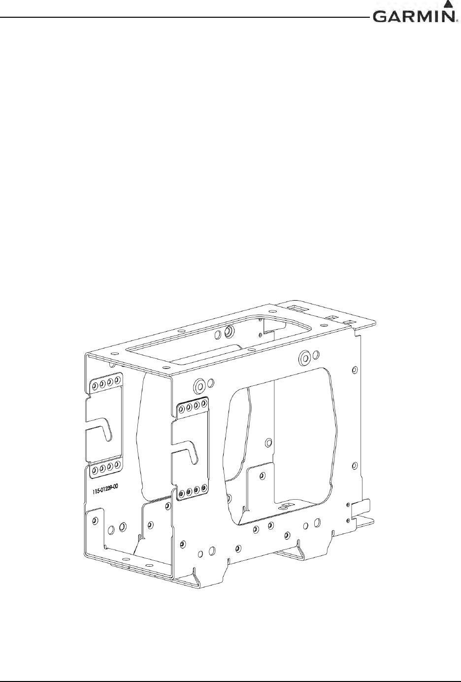
190-00303-05 GIA 63 Installation Manual
Rev. W Page 2-15
2.8.3 Remote Mounted Stand-Alone Rack Considerations
Figure 2-3 and Figure B-4 show the GIA 63(W) remote mounted stand-alone rack. The remote rack can be
installed in a variety of locations, such as the electronics bay, under a seat, or on an avionics shelf behind
the rear baggage area. Refer to Figure 2-5 for suggested mounting locations. Leave sufficient clearance
between the GIA 63(W) and any obstruction. The rack should be mounted to a surface known to have
sufficient structural integrity to withstand additional inertia forces imposed by a 7.5-pound (3.4 kg) unit.
Figure B-3 gives the GIA 63(W) stand-alone rack dimensions. The rack can be mounted vertically using
four #8-32 pan head screws (MS35206, AN526, or other approved fastener). It can also be mounted
horizontally using four #6-32 100° counter-sunk flathead screws (MS24693, AN507R, or other approved
fastener). Ensure that the GIA 63(W) chassis has a ground path to the airframe by having at least one
mounting screw in contact with the airframe.
Figure 2-4 and Figure B-6 show the stand-alone rack used for the GIA 63H installation. Figure B-5 gives
the stand-alone rack dimensions for the GIA 63H. The rack can be mounted in any orientation using
screws as defined in Section 2.1.3. Ensure that the GIA 63H chassis has a ground path to the airframe by
having at least one mounting screw in contact with the airframe.
After the cable assemblies are made and wiring installed to the rack back plate, route wiring bundle as
appropriate. Use cable ties to secure the cable assemblies and coax to provide strain relief for the cable
assemblies.
Figure 2-3. GIA 63(W) Standalone Rack
DRAFT
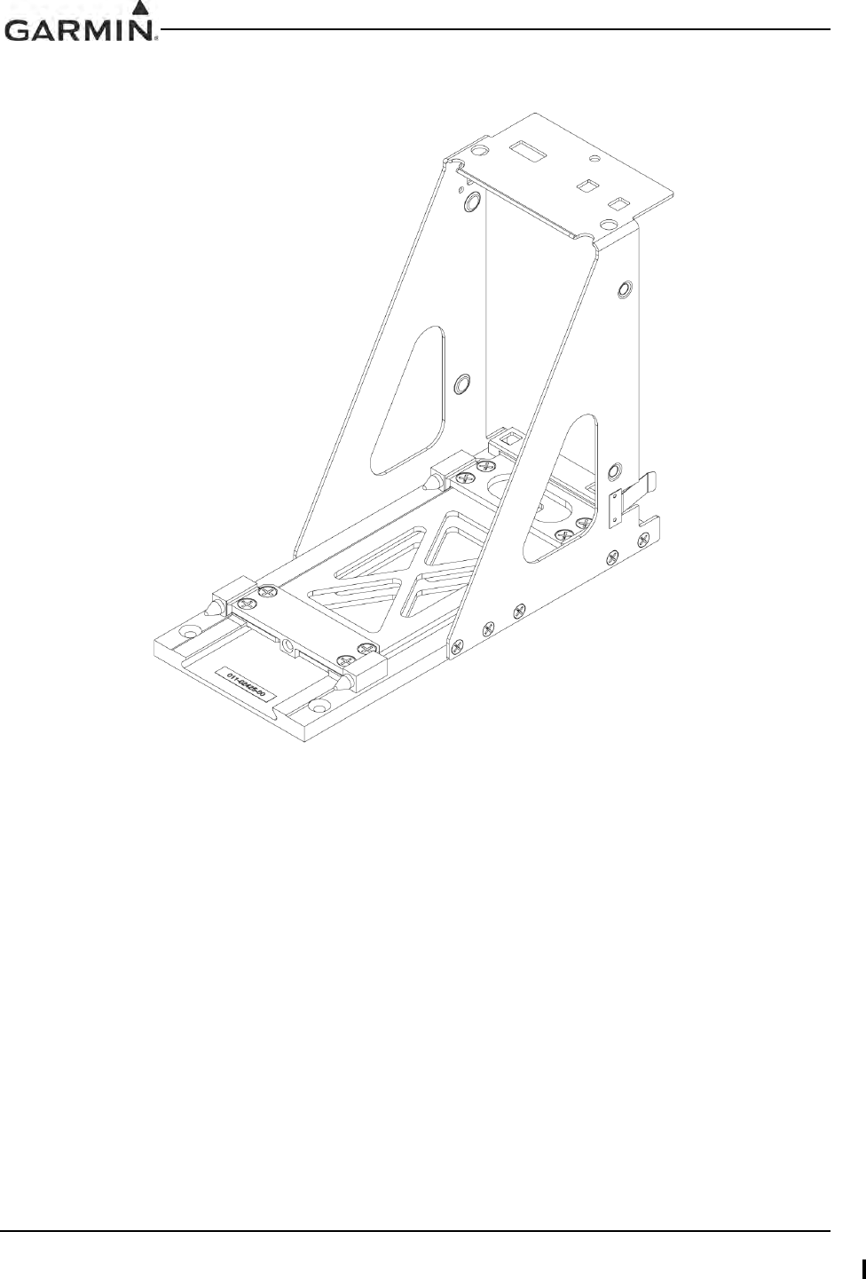
GIA 63 Installation Manual 190-00303-05
Page 2-16 Rev. V
Figure 2-4. GIA 63H Standalone Rack
DRAFT
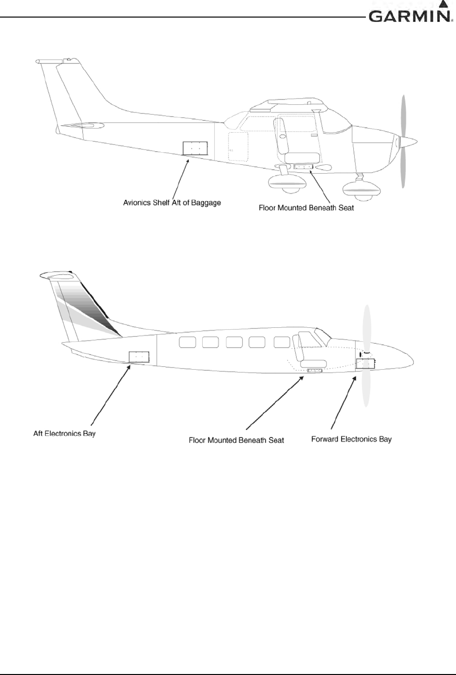
190-00303-05 GIA 63 Installation Manual
Rev. W Page 2-17
Figure 2-5. GIA 63(W) Standalone Rack, Suggested Mounting Locations
DRAFT

GIA 63 Installation Manual 190-00303-05
Page 2-18 Rev. V
This page intentionally left blank
DRAFT

190-00303-05 GIA 63 Installation Manual
Rev. V Page 3-1
3 INSTALLATION PROCEDURE
3.1 Unpacking Unit
Carefully unpack the equipment and make a visual inspection of the unit for evidence of damage incurred
during shipment. If the unit is damaged, notify the carrier and file a claim. To justify a claim, save the
original shipping container and all packing materials. Do not return the unit to Garmin until the carrier has
authorized the claim.
Retain the original shipping containers for storage. If the original containers are not available, a separate
cardboard container should be prepared that is large enough to accommodate sufficient packing material to
prevent movement.
DRAFT
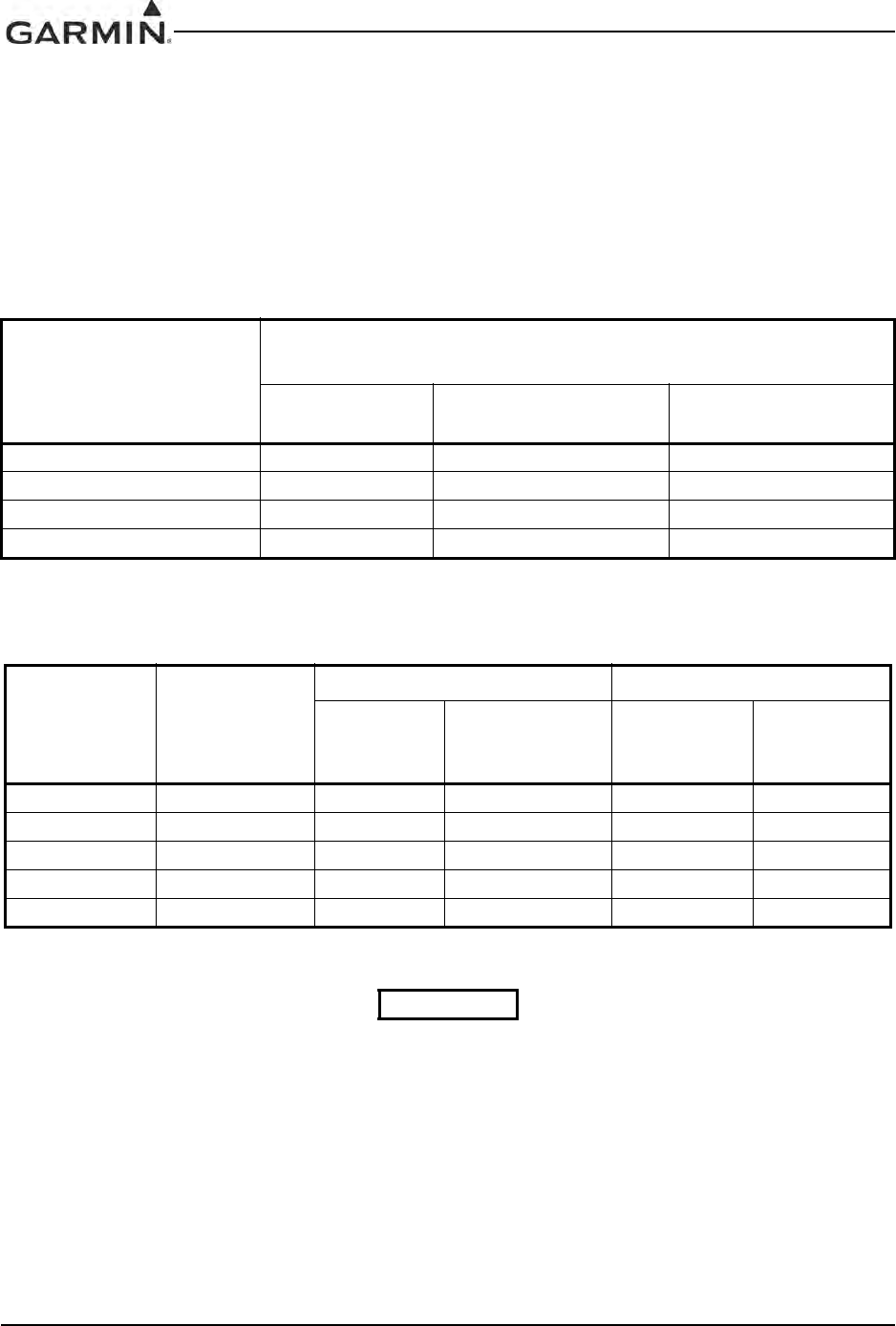
GIA 63 Installation Manual 190-00303-05
Page 3-2 Rev. V
3.2 Wiring Harness Installation
Allow adequate space for installation of cables and connectors. The installer shall supply and fabricate all
of the cables. All electrical connections are made through 44, 62, and 78-pin D subminiature connectors.
Section 4 defines the electrical characteristics of all input and output signals. Required connectors and
associated hardware are supplied with the connector kit.
See Appendix C for examples of interconnect wiring diagrams. Construct the actual harnesses in
accordance with aircraft manufacturer authorized interconnect standards.
1. Non-Garmin part numbers shown are not maintained by Garmin and consequently are subject to
change without notice.
2. Extraction of 16 and 18 AWG contacts requires that the expanded wire barrel be cut off from the
contact. It may also be necessary to push the pin out from the face of the connector when using an
extractor due to the absence of the wire. A new contact must be used when reassembling the
connector.
3. For applications using 16 AWG wire, contact Garmin for information regarding connector crimp
positioner tooling.
Table 3-1. Pin Contact Part Numbers
Manufacturer
78 pin connectors (P603, 605, 606), 62 pin connectors (P602), 44 pin
connectors (P604 and P601)
16 AWG
(Power Only) 18-20 AWG
(Power Only) 22-28 AWG
Garmin P/N 336-00044-01 336-00044-00 336-00021-00
Military P/N N/A N/A M39029/58-360
AMP N/A N/A 204370-02
Positronic N/A N/A MC8522D
Table 3-2. Recommended Crimp Tools
Manufacturer Hand
Crimping Tool
18-20 AWG 22-28 AWG
Positioner Insertion/
Extraction Tool
(Note 2) Positioner Insertion/
Extraction
Tool
Military P/N M22520/2-01 N/A M81969/1-04 M22520/2-09 M81969/1-04
Positronic 9507 9502-11 M81969/1-04 9502-3 M81969/1-04
AMP 601966-1 N/A 91067-1 601966-6 91067-1
Daniels AFM8 K774 M81969/1-04 K42 M81969/1-04
Astro 615717 N/A M81969/1-04 615725 M81969/1-04
NOTES
DRAFT
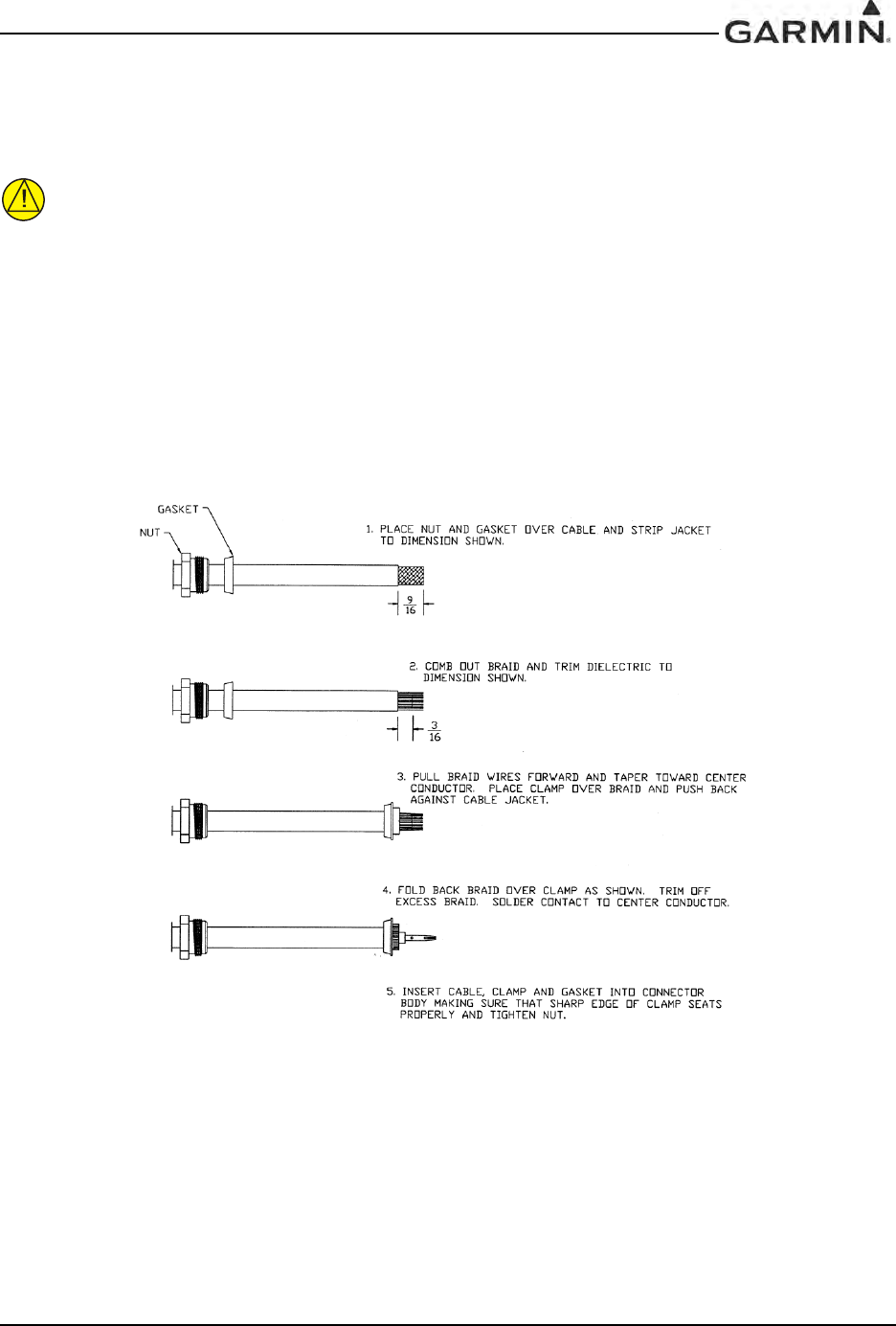
190-00303-05 GIA 63 Installation Manual
Rev. V Page 3-3
3.3 Antenna Installation
For the COM, VOR/LOC, and Glideslope antenna, follow the manufacturers’ instructions. Avoid running
other wires and coaxial cables near the VOR/LOC antenna cable.
CAUTION
Do not use construction grade RTV sealant or sealants containing acetic acid. These
sealants may damage the electrical connections to the antenna. Use of these type sealants
may void the antenna warranty.
3.4 Cable Installation
1. Route the coaxial cable to the rack location keeping in mind the recommendations of Section 2.
Secure the cable in accordance with good aviation practice.
2. Trim the coaxial cable to the desired length and install the BNC connector (330-00087-00) per the
cabling instructions on Figure 3-1. If the connector is provided by the installer, follow the
connector manufacturer’s instructions for cable preparation.
Figure 3-1. Coaxial Cable Installation
3. Contacts for the 78, 62, and 44 pin connectors must be crimped onto the individual wires of the
aircraft wiring harness. Tables 3-1 and 3-2 list contact part numbers (for reference) and
recommended crimp tools.
DRAFT

GIA 63 Installation Manual 190-00303-05
Page 3-4 Rev. V
3.5 Backshell Assembly
The GIA 63(X) connector kit includes six Garmin backshell connectors. The backshell assemblies house
the configuration module/temperature sensor, if applicable. Garmin’s backshell also gives the installer the
ability to easily terminate shield grounds at the backshell housing using one of two methods available
(SPIDER or Shield Block). To assemble the backshell and configuration module refer to instructions
provided in the G1000 System Installation Manual (190-00303-00), as well as the SPIDER Installation
Instructions (190-00313-03) and Shield Block Installation Instructions (190-00313-09).
NOTE
Information about the SPIDER grounding system is provided in support of existing
installations. All new installations shall use the SHIELD BLOCK grounding system.
3.6 Unit Installation
Installation instructions for the GIA 63(W)
For installation and assembly, refer to the outline and installation drawings shown in Appendix B of this
manual.
1. Assemble the backshell connectors, refer to Section 3.5.
2. Connect backshell connectors to the rear plate using the provided screws.
3. Mount the unit rack to the main system rack or other suitable mounting location, using the
nutplates provided for the modular rack or appropriate hardware from Section 2.1.3 for the
standalone rack.
4. Assemble the NAV and Main rear plates into the GIA 63(W) unit rack.
5. Carefully slide the GIA 63(W) into the rack. Ensure that the orientation of the unit allows for the
engagement of the locking stud in the channel on the rack. The unit can only be installed in one
direction.
6. Push the GIA 63(W) lever down towards the bottom of the unit. This engages the locking stud
with the dogleg slot and locks unit into the rack. If there is excessive resistance, do not force the
unit.
7. Lock the handle into the GIA 63(W) body and tighten the Phillips screw (or push in the D-Ring
and twist clockwise 90°, for units with a D-Ring).
CAUTION
Do not use excessive force when inserting the GIA 63(W) into the rack. This may cause
damage to the connectors, unit and/or unit rack. If excessive resistance is felt during
installation, stop! Remove the GIA 63(W) and identify the source of resistance. The rear
plates are designed to float in the unit rack. Check to ensure the rear plates are not bound
by the connectors or spring clip.
DRAFT
190-00303-05 GIA 63 Installation Manual
Rev. V Page 3-5
Installation instructions for the GIA 63(H)
For installation and assembly, refer to the outline and installation drawings shown in Appendix B of this
manual.
1. Assemble the backshell connectors, refer to Section 3.5.
2. Connect backshell connectors to the rear plate using the provided screws.
3. Mount the unit rack to a suitable mounting location, using appropriate hardware from Section
2.1.3 for the helicopter rack.
4. Assemble the NAV and Main rear plates into the GIA 63H unit rack.
5. Carefully place the GIA 63H onto the rack, making sure that the mounting hardware on the bottom
of the unit closest to the connectors clears the first set of spring pins on the rack. Once the unit is
placed on the rack, slide the unit into the rack until the install screw makes contact. The unit can
only be installed in one direction.
6. Using a Hex Driver, tighten the unit into the rack via the install screw. Tighten the screw to the
torque specified in Appendix B.
CAUTION
Do not use excessive force when inserting the GIA 63H into the rack. This may cause
damage to the connectors, unit and/or unit rack. If excessive resistance is felt during
installation, stop! Remove the GIA 63H and identify the source of resistance. The rear
plates are designed to float in the unit rack. Check to ensure the rear plates are not bound
by the connectors or spring clip.
NOTE
The install screw is designed with a ratcheting socket that resists turning
counterclockwise, unless pushed in. This ensures that the engagement screw cannot loosen
under vibration.
3.7 Post Installation Configuration & Checkout
All configuration and checkout procedures take place upon completion of the installation of the Garmin
Integrated Flight Deck. The GDU serves as the graphics user interface to the installer configuring the
system. For sample configuration and checkout procedures, refer to the G1000 Line Maintenance and
Configuration Manual, Garmin part number 190-00303-04. Always use aircraft manufacturer approved
checkout documents when performing actual checkout.
DRAFT
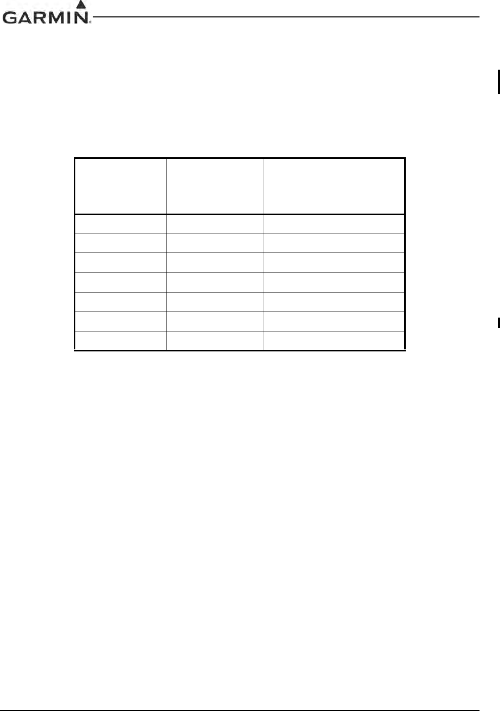
GIA 63 Installation Manual 190-00303-05
Page 3-6 Rev. V
3.8 Continued Airworthiness
Maintenance of the GIA 63(X) is “on condition” for all units installed in airframes that require power
interrupt Category B (50mS). For airframes that require the GIA 63(X) to comply with RTCA/DO-160D
or RTCA/DO-160E (as specified in applicable Environmental Qualification Form) power interrupt
Category A (200mS), one of the following two actions must be taken to ensure backup time is adequate:
• Comply with the applicable GIA 63(X) Mod Status (refer to Table 3-3).
Or
• Perform the power interrupt annual inspection as described in Section 3.8.1.
Table 3-3. Long Term Power Interrupt Category A (200 mS) Mod Status
Unit Unit Part Number
Long Term
Power Interrupt
Category A (200 mS)
Mod Status
GIA 63 011-00781-00 4
GIA 63 011-00781-01 1
GIA 63W 011-01105-00 1
GIA 63W 011-01105-01 0
GIA 63W 011-01105-20 0
GIA 63W 011-01105-40 0
GIA 63H 011-01105-30 0
DRAFT
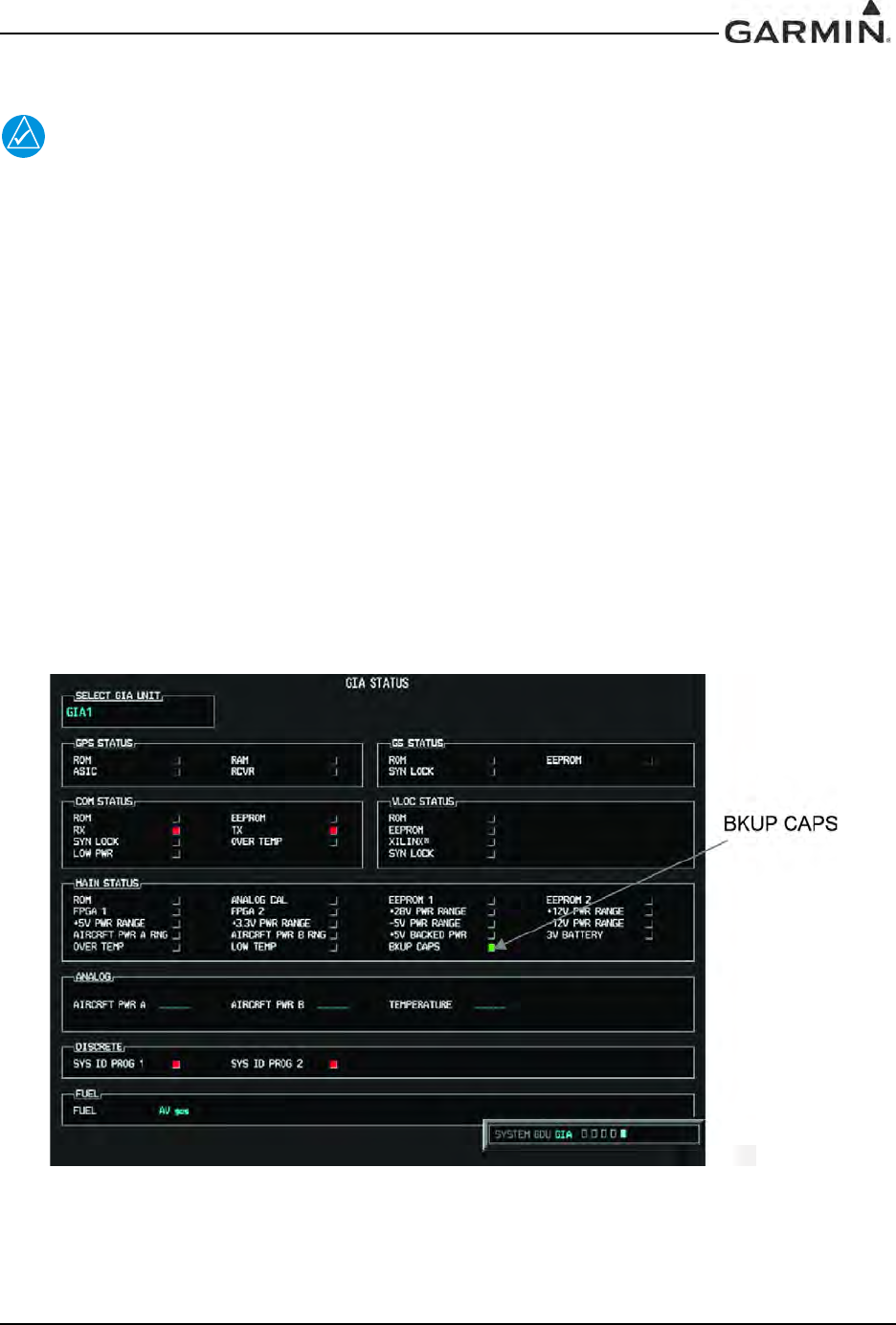
190-00303-05 GIA 63 Installation Manual
Rev. V Page 3-7
3.8.1 Category A Long Term Power Interrupt Annual Inspection
NOTE
In order to comply with this procedure GIA 63 main software version must be 5.30 or later,
GIA 63W main software version must be 5.21 or later, and GDU main software version
must be 7.10 or later.
1. Verify the air temperature around both GIA’s is at least 70° Fahrenheit.
2. Apply power to both GIA’s.
3. Leave both GIA’s on for 10 minutes.
4. Remove power from both GIA’s.
5. Wait 30 seconds.
6. Apply power to both GIA’s.
7. Place the G1000 in Configuration mode by holding the ENT key on the GDU’s while applying
power.
8. Using the FMS knob go to the GIA STATUS page (Figure 3-2) on the PFD.
9. Verify the GIA #1 BKUP CAPS light is green. If the BKUP CAPS light is red, replace GIA #1
with a unit of mod status indicated in Table 3-3.
10. Using the FMS knob select GIA2 in the ‘SELECT GIA UNIT’ field.
11. Verify the GIA #2 BKUP CAPS light is green. If the BKUP CAPS light is red, replace GIA #2,
with a unit of mod status indicated in Table 3-3.
Figure 3-2. GIA STATUS Page
DRAFT

GIA 63 Installation Manual 190-00303-05
Page 3-8 Rev. V
This page intentionally left blank
DRAFT
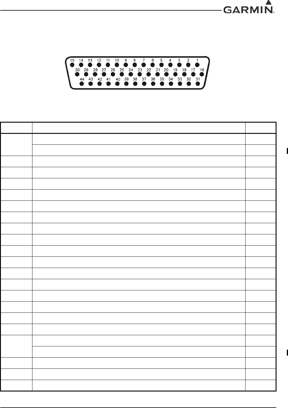
190-00303-05 GIA 63 Installation Manual
Rev. V Page 4-1
4 SYSTEM INTERCONNECTS
4.1 Pin Function List
4.1.1 P601 (COM)
Figure 4-1. View of J601 connector from back of unit
Table 4-1. P601 (COM) Pin List
Pin Pin Name I/O
1RESERVED (UNSQUELCHED AUDIO TEST) --
COM UNSQUELCHED AUDIO OUTPUT (011-01105-4X ONLY) Out
2RESERVED --
3RESERVED --
4COM MIC KEY* In
5RESERVED --
6RESERVED --
7COM MIC AUDIO IN HI In
8COM MIC AUDIO IN LO (GROUND) --
9COM 500Ω AUDIO OUT HI Out
10 COM 500Ω AUDIO OUT LO Out
11 TRANSMIT INTERLOCK* In
12 COM REMOTE TRANSFER* In
13 COM DIGITAL AUDIO OUT Out
14 ON-SIDE COM MIC DIGITAL AUDIO IN In
15 SIGNAL GROUND --
16 COM REMOTE POWER OFF In
17 AIRCRAFT POWER 1 In
18 SPARE --
CROSS-SIDE COM MIC DIGITAL AUDIO IN (011-01105-2X/-3X/-4X ONLY) In
19 AIRCRAFT POWER 1 In
20 SPARE --
21 AIRCRAFT POWER 1 In
DRAFT
GIA 63 Installation Manual 190-00303-05
Page 4-2 Rev. V
*Indicates Active Low (Ground to activate)
† Pin not currently supported
22 SPARE --
23 AIRCRAFT POWER 2 In
24 SPARE --
25 AIRCRAFT POWER 2 In
26 SPARE --
27 AIRCRAFT POWER 2 In
28 RESERVED --
29 RESERVED --
30 POWER GROUND --
31 POWER GROUND --
32 RESERVED --
33 RESERVED --
34 COM SECONDARY TX INTERLOCK* (011-01105-4X ONLY) In
35 RESERVED --
36 RESERVED --
37 RESERVED --
38 RESERVED --
39 RESERVED --
40 RESERVED --
41 RESERVED --
42 RESERVED --
43 POWER GROUND --
44 POWER GROUND --
Table 4-1. P601 (COM) Pin List
Pin Pin Name I/O
DRAFT
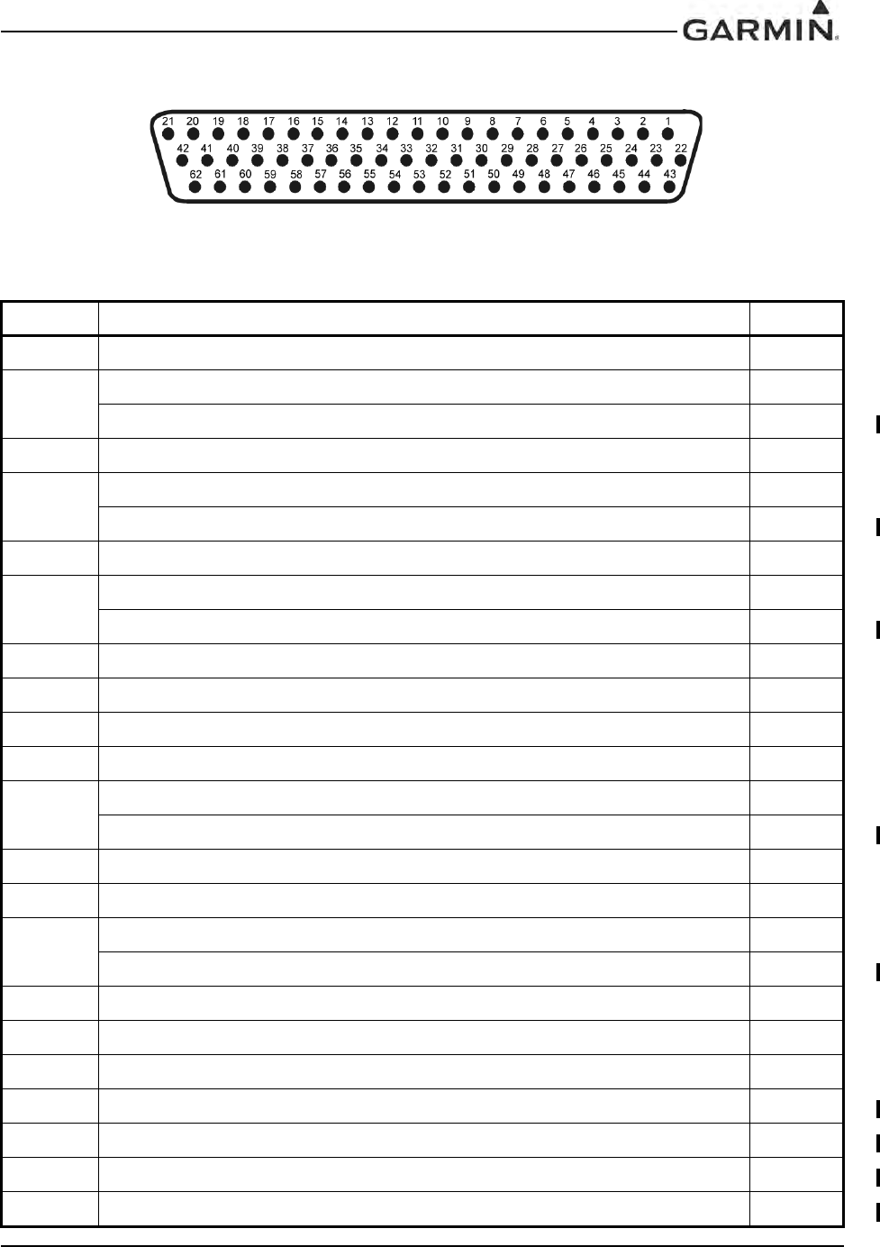
190-00303-05 GIA 63 Installation Manual
Rev. V Page 4-3
4.1.2 P602 (VOR/ILS)
Figure 4-2. View of J602 connector from back of unit
Table 4-2. P602 (VOR/ILS) Pin List
Pin Pin Name I/O
1VOR/LOC +TO Out
2VOR/LOC +FROM (VOR/LOC COMMON) Out
VOR/LOC +FROM (NAV COMMON) (011-01105-2X/-3X/-4X ONLY) Out
3VOR/LOC +FLAG Out
4VOR/LOC -FLAG (VOR/LOC COMMON) Out
VOR/LOC -FLAG (NAV COMMON) (011-01105-2X/-3X/-4X ONLY) Out
5VOR/LOC +LEFT Out
6VOR/LOC +RIGHT (VOR/LOC COMMON) Out
VOR/LOC +RIGHT (NAV COMMON) (011-01105-2X/-3X/-4X ONLY) Out
7RESERVED --
8VOR/LOC COMPOSITE OUT Out
9VOR OBS ROTOR C Out
10 VOR OBS ROTOR H (GROUND) --
11 VOR OBS STATOR E (VOR/LOC COMMON) Out
VOR OBS STATOR E (NAV COMMON) (011-01105-2X/-3X/-4X ONLY) Out
12 VOR OBS STATOR F In
13 VOR OBS STATOR D In
14 VOR OBS STATOR G (VOR/LOC COMMON) Out
VOR OBS STATOR G (NAV COMMON) (011-01105-2X/-3X/-4X ONLY) Out
15 VOR/LOC SUPERFLAG Out
16 VOR/LOC 500Ω AUDIO OUT HI Out
17 VOR/LOC 500Ω AUDIO OUT LO Out
18 KING SERIAL DME CLOCK (011-00781-0X AND 011-01105-0X ONLY) Out
19 KING SERIAL DME DATA (011-00781-0X AND 011-01105-0X ON LY) Out
20 KING SERIAL RNAV REQUEST (011-00781-0X AND 011-01105-0X ONLY) In
21 KING SERIAL RNAV* MODE (011-00781-0X AND 011-01105-0X ONLY)In
DRAFT

GIA 63 Installation Manual 190-00303-05
Page 4-4 Rev. V
22 SIGNAL GROUND --
23 VOR/ILS ARINC 429 OUT B Out
24 VOR/ILS ARINC 429 OUT A Out
25 VOR OBI CLOCK Out
26 VOR OBI SYNC Out
27 VOR OBI DATA Out
28 VOR/ILS REMOTE TRANSFER* In
29 ILS ENERGIZE* Out
30 RESERVED --
31 RESERVED --
32 GLIDESLOPE +FLAG Out
33 PARALLEL DME 1 MHZ-D Out
34 GLIDESLOPE +UP Out
35 VOR/ILS ARINC 429 IN B In
36 VOR/ILS ARINC 429 IN A In
37 PARALLEL DME 100 KHZ-A Out
38 GLIDESLOPE SUPERFLAG Out
39 PARALLEL DME 100 KHZ-B Out
40 PARALLEL DME 100 KHZ-C Out
41 DME COMMON In
42 PARALLEL DME 100 KHZ-D Out
43 PARALLEL DME 50 KHZ Out
44 RESERVED --
45 PARALLEL DME 1 MHZ-A Out
46 PARALLEL DME 1 MHZ-B Out
47 PARALLEL DME 1 MHZ-C Out
48 RESERVED --
49 SIGNAL GROUND --
50 RESERVED --
51 SPARE --
52 SPARE --
Table 4-2. P602 (VOR/ILS) Pin List
Pin Pin Name I/O
DRAFT
190-00303-05 GIA 63 Installation Manual
Rev. V Page 4-5
*Indicates Active Low (Ground to activate)
† Pin not currently supported
53 GLIDESLOPE –FLAG (GLIDESLOPE COMMON) Out
GLIDESLOPE –FLAG (NAV COMMON) (011-01105-2X/-3X/-4X ONLY) Out
54 PARALLEL DME 100KHZ-E Out
55 GLIDESLOPE +DOWN (GLIDESLOPE COMMON) Out
GLIDESLOPE +DOWN (NAV COMMON) (011-01105-2X/-3X/-4X ONLY) Out
56 PARALLEL DME 1MHZ-E Out
57 RESERVED --
58 SPARE --
GLIDESLOPE COMPOSITE OUT (011-01105-2X/-3X/-4X ONLY) Out
59 VOR/LOC DIGITAL AUDIO OUT Out
60 SIGNAL GROUND --
61 POWER GROUND --
62 POWER GROUND --
Table 4-2. P602 (VOR/ILS) Pin List
Pin Pin Name I/O
DRAFT
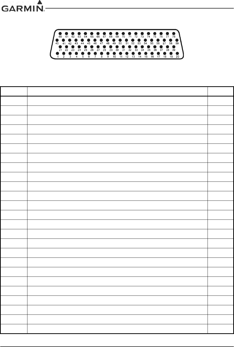
GIA 63 Installation Manual 190-00303-05
Page 4-6 Rev. V
4.1.3 P603 (Main Serial)
Figure 4-3. View of J603 connector from back of unit
Table 4-3. P603 Main Serial
Pin Pin Name I/O
1RESERVED --
2ETHERNET OUT A Out
3ETHERNET OUT B Out
4RS-485 4 A I/O
5RS-485 4 A I/O
6RS-485 4 B I/O
7RS-485 4 B I/O
8MAIN ARINC 429 IN 3 A In
9MAIN ARINC 429 IN 3 B In
10 MAIN ARINC 429 IN 4 A In
11 MAIN ARINC 429 IN 4 B In
12 MAIN ARINC 429 IN 5 A In
13 MAIN ARINC 429 IN 5 B In
14 MAIN ARINC 429 IN 6 A In
15 MAIN ARINC 429 IN 6 B In
16 MAIN ARINC 429 IN 7 A In
17 MAIN ARINC 429 IN 7 B In
18 MAIN ARINC 429 IN 8 A In
19 MAIN ARINC 429 IN 8 B In
20 CAN BUS 1 HI I/O
21 RESERVED --
22 CAN BUS 1 LO I/O
23 RS-485 1 A I/O
24 RS-485 1 B I/O
25 RS-485 2 A I/O
DRAFT

190-00303-05 GIA 63 Installation Manual
Rev. V Page 4-7
26 RS-485 2 B I/O
27 RS-485 3 A/RS-422 IN A I/O
28 RS-485 3 B/RS-422 IN B I/O
29 MAIN ARINC 429 IN 1 A In
30 CAN BUS 2 LO I/O
31 MAIN ARINC 429 IN 1 B In
32 CAN BUS 2 H I/O
33 MAIN ARINC 429 IN 2 A In
34 CAN BUS 1 TERMINATION --
35 MAIN ARINC 429 IN 2 B In
36 RS-485 5 A/RS-422 OUT A I/O
37 RS-485 5 B/RS-422 OUT B I/O
38 RESERVED --
39 CAN BUS 2 TERMINATION --
40 RESERVED --
41 MAIN RS-232 IN 1 In
42 SIGNAL GROUND --
43 MAIN RS-232 OUT 1 Out
44 MAIN RS-232 IN 2 In
45 SIGNAL GROUND --
46 MAIN RS-232 OUT 2 Out
47 MAIN RS-232 IN 3 In
48 SIGNAL GROUND --
49 MAIN RS-232 OUT 3 Out
50 MAIN RS-232 IN 4 In
51 SIGNAL GROUND --
52 MAIN RS-232 OUT 4 Out
53 MAIN RS-232 IN 5 In
54 SIGNAL GROUND --
55 MAIN RS-232 OUT 5 Out
56 MAIN RS-232 IN 6 In
57 SIGNAL GROUND --
Table 4-3. P603 Main Serial
Pin Pin Name I/O
DRAFT

GIA 63 Installation Manual 190-00303-05
Page 4-8 Rev. V
*Indicates Active Low (Ground to activate)
† Pin not currently supported
58 MAIN RS-232 OUT 6 Out
59 MAIN RS-232 IN 7 In
60 RESERVED --
61 SIGNAL GROUND --
62 MAIN RS-232 OUT 7 Out
63 MAIN RS-232 IN 8 In
64 SIGNAL GROUND --
65 MAIN RS-232 OUT 8 Out
66 RESERVED --
67 GPS PPS OUT Out
68 RESERVED --
69 VOICE ALERT DIGITAL AUDIO OUT Out
70 MAIN ARINC 429 OUT 1 B Out
71 MAIN ARINC 429 OUT 1 A Out
72 MAIN ARINC 429 OUT 2 B Out
73 MAIN ARINC 429 OUT 2 A Out
74 MAIN ARINC 429 OUT 3 B Out
75 MAIN ARINC 429 OUT 3 A Out
76 ETHERNET IN A In
77 ETHERNET IN B In
78 RESERVED --
Table 4-3. P603 Main Serial
Pin Pin Name I/O
DRAFT

190-00303-05 GIA 63 Installation Manual
Rev. V Page 4-9
4.1.4 P604 (Main Discrete)
Figure 4-4. View of J604 connector from back of unit
Table 4-4. P604 (Main Discrete) Pin List
Pin Pin Name I/O
1ANNUNCIATE* 22 Out
2VOICE ALERT 500Ω AUDIO OUT HI Out
3VOICE ALERT 500Ω AUDIO OUT LO Out
4DISCRETE IN 13 In
5DISCRETE IN 14 In
6ANNUNCIATE* 1 Out
7DISCRETE IN* 1 In
8DISCRETE IN* 2 In
9DISCRETE IN* 3 In
10 DISCRETE IN 15 In
11 AUTOPILOT DISCONNECT IN In
12 DISCRETE IN* 4 In
13 DISCRETE IN* 5 In
14 DISCRETE IN* 6 In
15 DISCRETE IN 16 In
16 DISCRETE IN 17 In
17 DISCRETE IN* 7 In
18 DISCRETE IN* 8 In
19 DISCRETE IN* 9 In
20 DISCRETE IN* 10 In
21 DISCRETE IN* 11 In
22 GIA SYSTEM ID PROGRAM* 1 In
23 GIA SYSTEM ID PROGRAM* 2 In
24 DISCRETE IN* 12 In
25 ANNUNCIATE* 2 Out
DRAFT

GIA 63 Installation Manual 190-00303-05
Page 4-10 Rev. V
*Indicates Active Low (Ground to activate)
† Pin not currently supported
26 ANNUNCIATE* 3 Out
27 ANNUNCIATE* 4 Out
28 ANNUNCIATE* 5 Out
29 ANNUNCIATE* 6 Out
30 ANNUNCIATE* 7 Out
31 ANNUNCIATE* 8 Out
32 ANNUNCIATE* 9 Out
33 ANNUNCIATE* 10 Out
34 ANNUNCIATE* 11 Out
35 ANNUNCIATE* 12 Out
36 ANNUNCIATE* 13 Out
37 ANNUNCIATE* 14 Out
38 ANNUNCIATE* 15 Out
39 ANNUNCIATE* 16 Out
40 ANNUNCIATE* 17 Out
41 ANNUNCIATE* 18 Out
42 ANNUNCIATE* 19 Out
43 ANNUNCIATE* 20 Out
44 ANNUNCIATE* 21 Out
Table 4-4. P604 (Main Discrete) Pin List
Pin Pin Name I/O
DRAFT
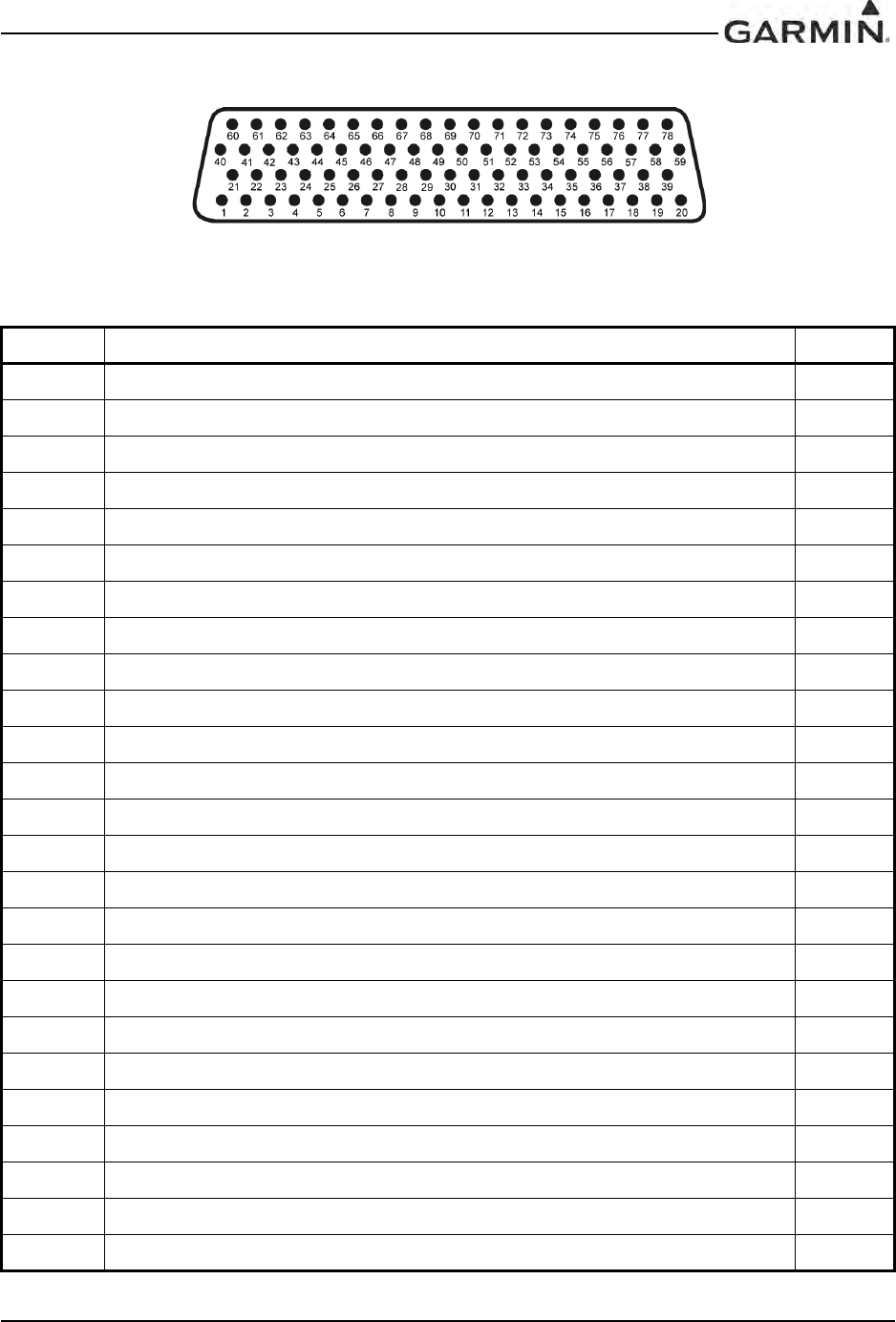
190-00303-05 GIA 63 Installation Manual
Rev. V Page 4-11
4.1.5 P605 (I/O 1)
Figure 4-5. View of J605 connector from back of unit
Table 4-5. P605 (I/O 1) Pin List
Pin Pin Name I/O
1RADAR ALTIMETER DC HI† In
2RADAR ALTIMETER DC LO† In
3DISCRETE IN 18A In
4SPARE --
5SPARE --
6SPARE --
7SPARE --
8FLIGHT DIRECTOR PITCH +UP In
9FLIGHT DIRECTOR PITCH +DOWN In
10 FLIGHT DIRECTOR ROLL +RIGHT In
11 FLIGHT DIRECTOR ROLL +LEFT In
12 DISCRETE IN 19A In
13 POTENTIOMETER SIGNAL IN† In
14 POTENTIOMETER REF IN HI† In
15 POTENTIOMETER REF IN LO† In
16 DISCRETE IN 20A In
17 MAIN LATERAL DEVIATION +LEFT Out
18 MAIN LATERAL DEVIATION +RIGHT (MAIN COMMON) Out
19 MAIN LATERAL +FLAG Out
20 MAIN LATERAL –FLAG (MAIN COMMON) Out
21 SPARE --
22 SPARE --
23 MAIN VERTICAL DEVIATION +UP Out
24 MAIN VERTICAL DEVIATION +DOWN (MAIN COMMON) Out
25 MAIN VERTICAL +FLAG Out
DRAFT

GIA 63 Installation Manual 190-00303-05
Page 4-12 Rev. V
26 MAIN VERTICAL –FLAG (MAIN COMMON) Out
27 SPARE --
28 SPARE --
29 AIRCRAFT POWER 1 In
30 POTENTIOMETER SIGNAL OUT† Out
31 AIRCRAFT POWER 1 In
32 POTENTIOMETER REF OUT HI† Out
33 AIRCRAFT POWER 2 In
34 POTENTIOMETER REF OUT LO (GROUND)† Out
35 AIRCRAFT POWER 2 In
36 GIA REMOTE POWER OFF In
37 DISCRETE IN* 1A In
38 DISCRETE IN* 2A In
39 DISCRETE IN* 3A In
40 DISCRETE IN* 4A In
41 DISCRETE IN* 5A In
42 DISCRETE IN* 6A In
43 DISCRETE IN* 7A In
44 DISCRETE IN* 8A In
45 DISCRETE IN* 9A In
46 DISCRETE IN* 10A In
47 DISCRETE OUT* 1A Out
48 SIGNAL GROUND --
49 DISCRETE IN* 11A In
50 DISCRETE IN 21A In
51 DISCRETE IN 22A In
52 DISCRETE IN* 12A In
53 DISCRETE IN* 13A In
54 DISCRETE IN* 14A In
55 DISCRETE IN* 15A In
56 OUTER MARKER LAMP IN In
57 MIDDLE MARKER LAMP IN In
Table 4-5. P605 (I/O 1) Pin List
Pin Pin Name I/O
DRAFT

190-00303-05 GIA 63 Installation Manual
Rev. V Page 4-13
*Indicates Active Low (Ground to activate)
† Pin not currently supported
58 AIRWAY/INNER MARKER LAMP IN In
59 DISCRETE IN* 16A In
60 DISCRETE IN 23A In
61 SIGNAL GROUND --
62 MAIN LATERAL SUPERFLAG Out
63 MAIN VERTICAL SUPERFLAG Out
64 SUPERFLAG 4A Out
65 SPARE --
66 SPARE --
67 SUPERFLAG 1A Out
68 DISCRETE OUT* 2A Out
69 DISCRETE OUT* 3A Out
70 DISCRETE OUT* 4A Out
71 ANNUNCIATE* 1A Out
72 ANNUNCIATE* 2A Out
73 DISCRETE IN* 17A In
74 DISCRETE IN 24A In
75 SUPERFLAG 2A Out
76 POWER GROUND --
77 SUPERFLAG 3A Out
78 POWER GROUND --
Table 4-5. P605 (I/O 1) Pin List
Pin Pin Name I/O
DRAFT
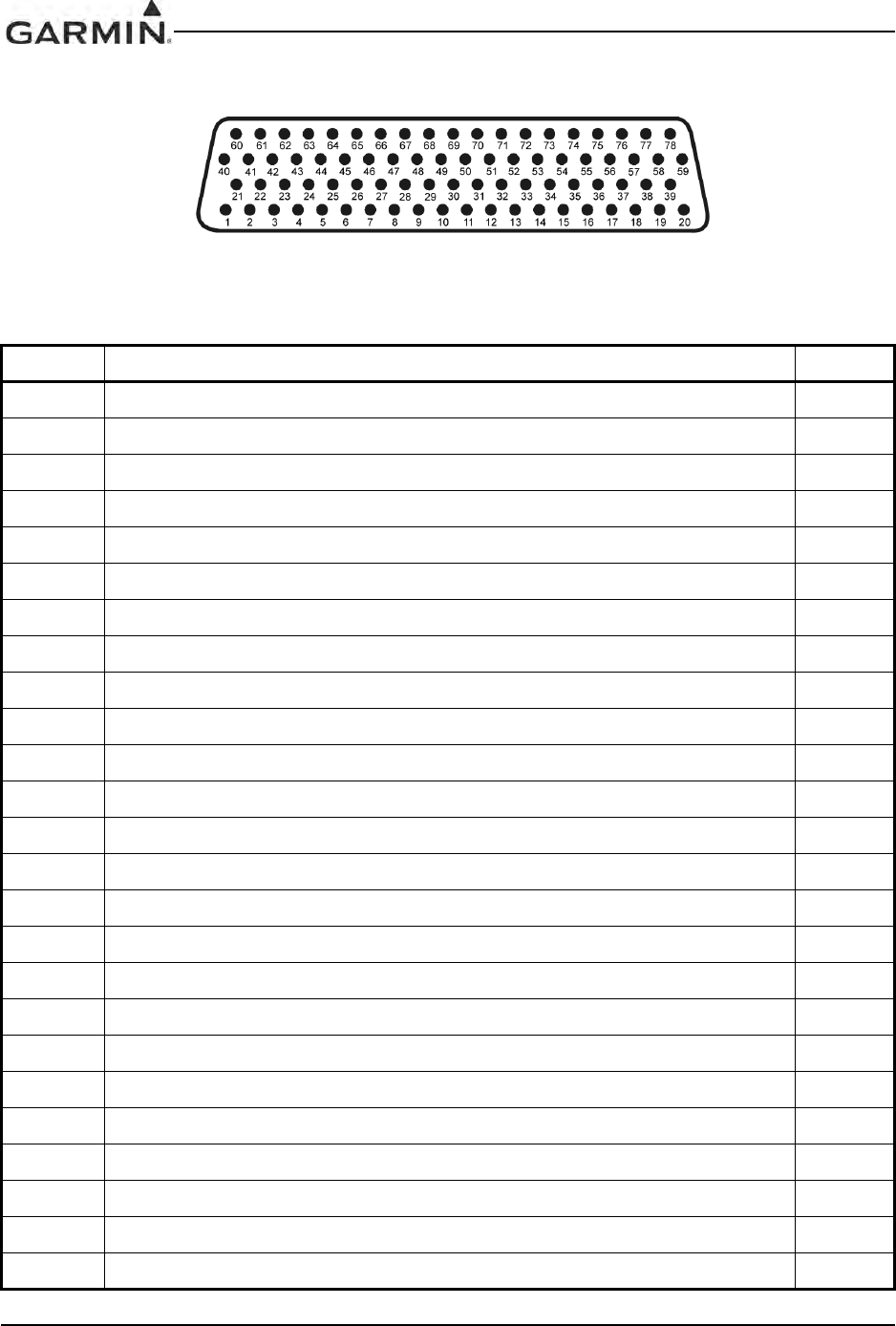
GIA 63 Installation Manual 190-00303-05
Page 4-14 Rev. V
4.1.6 P606 (I/O 2)
Figure 4-6. View of J606 connector from back of unit
Table 4-6. P606 (I/O 2) Pin List
Pin Pin Name I/O
126 VAC VERTICAL GYRO REF HI† In
226 VAC VERTICAL GYRO REF LO† In
326 VAC ADF REF HI† In
426 VAC ADF REF LO† In
526 VAC AFCS REF HI† In
626 VAC AFCS REF LO† In
7DIRECTIONAL GYRO MOTOR A† In
8DIRECTIONAL GYRO MOTOR B† In
9SIGNAL GROUND --
10 ADF X/COS In
11 ADF Y/SIN In
12 ADF Z (GROUND) In
13 SIGNAL GROUND --
14 HEADING X† In
15 HEADING Y† In
16 HEADING Z (GROUND)† In
17 SIGNAL GROUND --
18 PITCH ATTITUDE X† In
19 PITCH ATTITUDE Y† In
20 PITCH ATTITUDE Z (GROUND)† In
21 ROLL ATTITUDE X† In
22 ROLL ATTITUDE Y† In
23 ROLL ATTITUDE Z (GROUND)† In
24 SIGNAL GROUND --
25 SPARE --
DRAFT

190-00303-05 GIA 63 Installation Manual
Rev. V Page 4-15
26 SPARE --
27 SPARE --
28 SPARE --
29 RESERVED --
30 SIGNAL GROUND --
31 RESERVED --
32 ADF DC REF IN In
33 RESERVED --
34 ANALOG ROLL STEERING H Out
35 RESERVED --
36 ANALOG ROLL STEERING LO (GROUND) Out
37 HEADING BOOTSTRAP OUT X† Out
38 HEADING BOOTSTRAP OUT Y† Out
39 HEADING BOOTSTRAP OUT Z (GROUND)† Out
40 AC ROLL ATTITUDE OUT HI† Out
41 AC ROLL ATTITUDE OUT LO (GROUND)† Out
42 AC PITCH ATTITUDE OUT HI† Out
43 AC PITCH ATTITUDE OUT LO (GROUND)† Out
44 YAW RATE +RIGHT† Out
45 YAW RATE +LEFT (GROUND)† Out
46 HEADING DATUM HI Out
47 HEADING DATUM LO (GROUND) Out
48 COURSE DATUM HI Out
49 COURSE DATUM LO (GROUND) Out
50 SIGNAL GROUND --
51 26 VAC DIRECTIONAL GYRO REF HI† In
52 26 VAC DIRECTIONAL GYRO REF LO† In
53 REMOTE ANNUNCIATE CLOCK In
54 REMOTE ANNUNCIATE DATA In
55 REMOTE ANNUNCIATE SYNC In
56 MAIN OBI CLOCK† Out
57 MAIN OBI DATA† Out
Table 4-6. P606 (I/O 2) Pin List
Pin Pin Name I/O
DRAFT

GIA 63 Installation Manual 190-00303-05
Page 4-16 Rev. V
*Indicates Active Low (Ground to activate)
† Pin not currently supported
58 MAIN OBI SYNC† Out
59 MAIN KING SERIAL DME DATA I/O
60 MAIN KING SERIAL DME CLOCK I/O
61 MAIN KING SERIAL DME HOLD* OUT† Out
62 MAIN KING SERIAL DME REQUEST Out
63 MAIN KING SERIAL DME ON* OUT† Out
64 MAIN KING SERIAL RNAV REQUEST† In
65 RESERVED --
66 RESERVED --
67 DISCRETE OUT* 1B Out
68 DISCRETE OUT* 2B Out
69 DISCRETE OUT* 3B Out
70 DISCRETE OUT* 4B Out
71 DISCRETE OUT* 5B Out
72 DISCRETE OUT* 6B Out
73 DISCRETE OUT* 7B Out
74 DISCRETE OUT* 8B Out
75 DISCRETE OUT* 9B Out
76 RESERVED --
77 DISCRETE OUT* 10B Out
78 RESERVED --
Table 4-6. P606 (I/O 2) Pin List
Pin Pin Name I/O
DRAFT
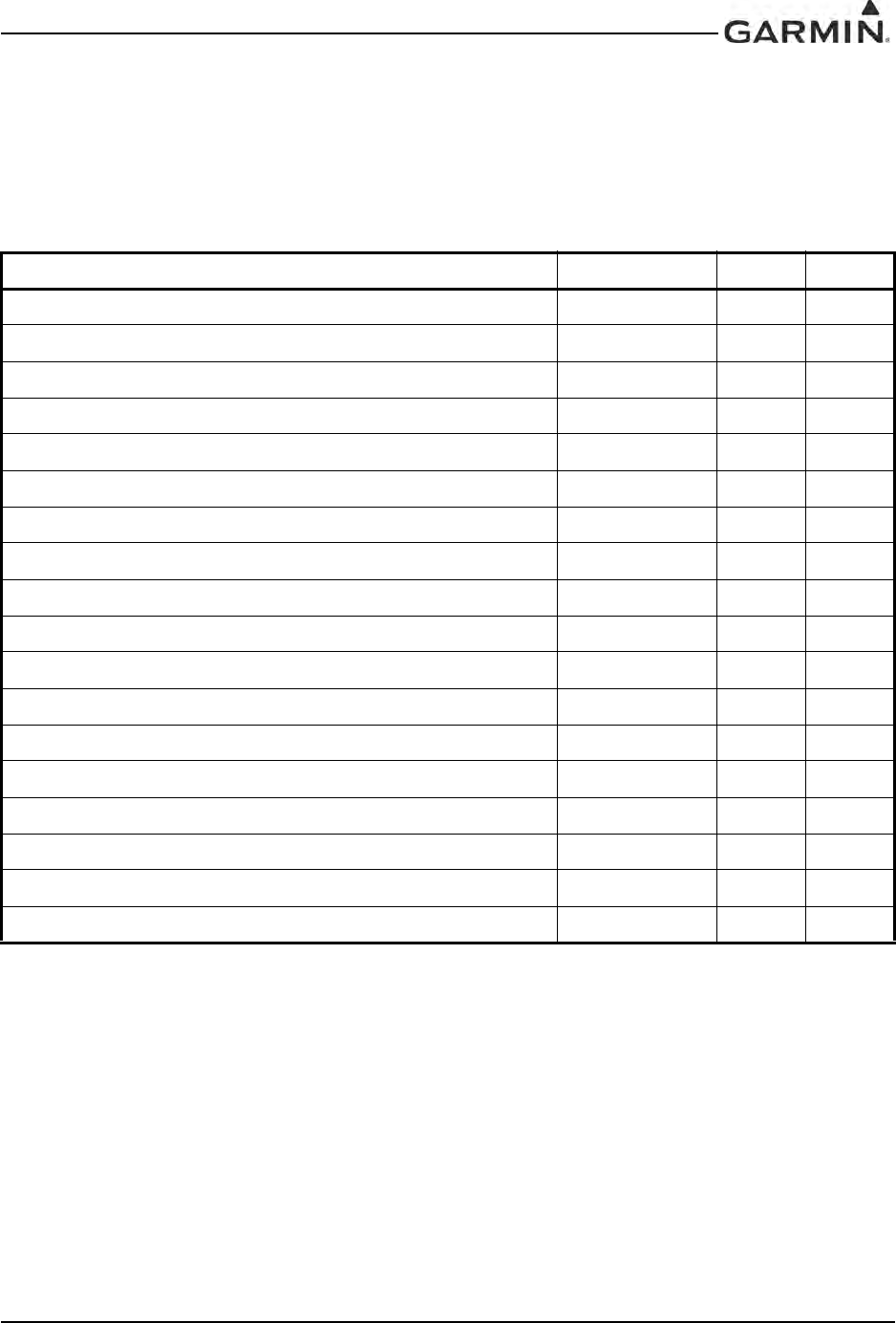
190-00303-05 GIA 63 Installation Manual
Rev. V Page 4-17
4.2 Power and Antennas
4.2.1 Power Functions
This section covers the power input requirements.
4.2.1.1 Aircraft Power
Pins 17, 19, and 21 of P601 are internally connected to form AIRCRAFT POWER 1. Pins 23, 25, and 27 of
P601 are internally connected to form AIRCRAFT POWER 2. AIRCRAFT POWER 1 and AIRCRAFT
POWER 2 are “diode ORed” to provide power redundancy. The same applies to pins 29/31 and pins 33/35
of P605.
Table 4-7. Aircraft Power
Pin Name Connector Pin I/O
AIRCRAFT POWER 1 P601 17 In
AIRCRAFT POWER 1 P601 19 In
AIRCRAFT POWER 1 P601 21 In
AIRCRAFT POWER 2 P601 23 In
AIRCRAFT POWER 2 P601 25 In
AIRCRAFT POWER 2 P601 27 In
AIRCRAFT POWER 1 P605 29 In
AIRCRAFT POWER 1 P605 31 In
AIRCRAFT POWER 2 P605 33 In
AIRCRAFT POWER 2 P605 35 In
POWER GROUND P601 30 --
POWER GROUND P601 31 --
POWER GROUND P601 43 --
POWER GROUND P601 44 --
POWER GROUND P602 61 --
POWER GROUND P602 62 --
POWER GROUND P605 76 --
POWER GROUND P605 78 --
DRAFT
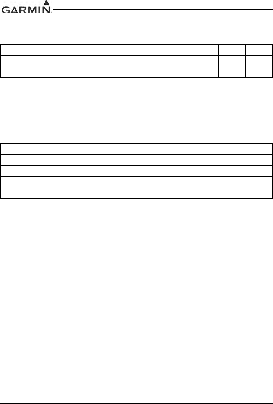
GIA 63 Installation Manual 190-00303-05
Page 4-18 Rev. V
4.2.1.2 Remote On/Off
INACTIVE: Vin ≤ 3.5VDC
ACTIVE: 10 ≤ Vin ≤ 33VDC with ≥ 75 uA source current
Source current is internally limited to 1.5 mA max for a 10-33VDC input
4.2.1.3 Antennas
Table 4-8. Remote On/Off
Pin Name Connector Pin I/O
GIA REMOTE POWER OFF P605 36 In
COM REMOTE POWER OFF P601 16 In
Table 4-9. Antennas
Pin Name Connector I/O
GPS ANTENNA P611 In
COM ANTENNA P612 In
VOR/LOC ANTENNA P613 In
GLIDESLOPE ANTENNA P614 In
DRAFT
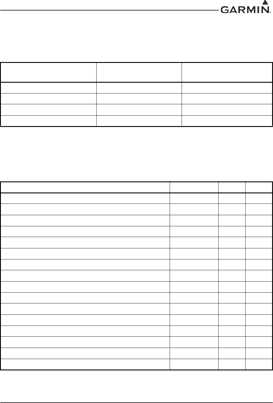
190-00303-05 GIA 63 Installation Manual
Rev. V Page 4-19
4.3 GIA System ID Program
The GIA 63(X) utilizes a hard strapping method to assign a unit ID to a unit. Unit ID’s identify a unit as a
#1, #2, #3, or #4 GIA.
4.4 Serial Data
4.4.1 Serial Data Electrical Characteristics
4.4.1.1 RS-232
The RS-232 outputs conform to EIA Standard RS-232C with an output voltage swing of at least ± 5V
when driving a standard RS-232 load.
Table 4-10. GIA System ID Program
GIA SYSTEM ID PROGRAM*
1 (P604, Pin 22)
GIA SYSTEM ID PROGRAM*
2 (P604, Pin 23) UNIT NUMBER
OPEN OPEN #1
GROUND OPEN #2
OPEN GROUND #3
GROUND GROUND #4
Table 4-11. RS-232
Pin Name Connector Pin I/O
MAIN RS-232 IN 1 P603 41 In
MAIN RS-232 OUT 1 P603 43 Out
MAIN RS-232 IN 2 P603 44 In
MAIN RS-232 OUT 2 P603 46 Out
MAIN RS-232 IN 3 P603 47 In
MAIN RS-232 OUT 3 P603 49 Out
MAIN RS-232 IN 4 P603 50 In
MAIN RS-232 OUT 4 P603 52 Out
MAIN RS-232 IN 5 P603 53 In
MAIN RS-232 OUT 5 P603 55 Out
MAIN RS-232 IN 6 P603 56 In
MAIN RS-232 OUT 6 P603 58 Out
MAIN RS-232 IN 7 P603 59 In
MAIN RS-232 OUT 7 P603 62 Out
MAIN RS-232 IN 8 P603 63 In
MAIN RS-232 OUT 8 P603 65 Out
DRAFT
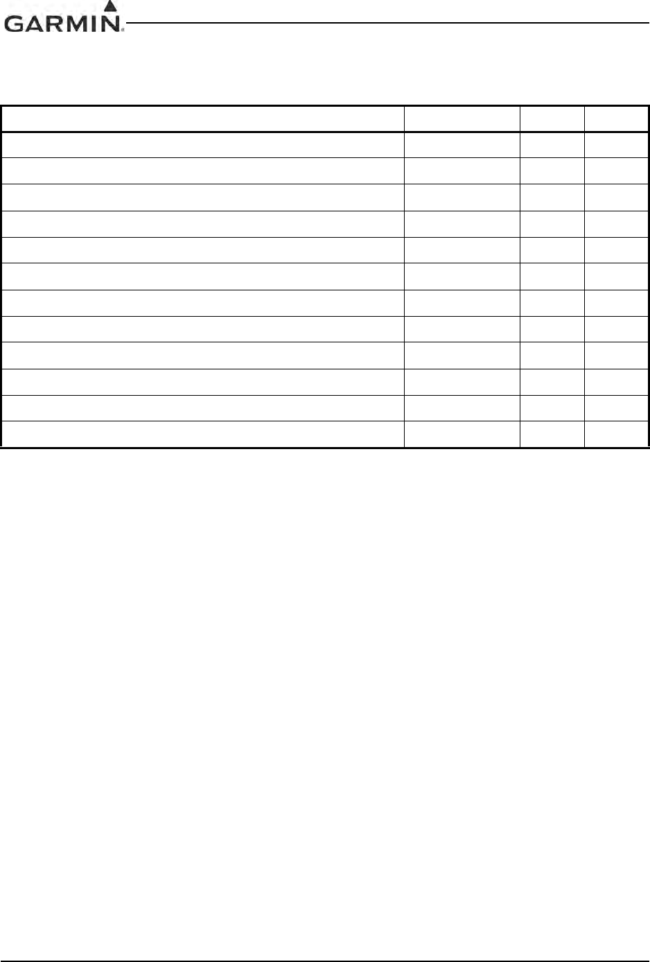
GIA 63 Installation Manual 190-00303-05
Page 4-20 Rev. V
4.4.1.2 RS-485/422
The GIA 63(X) contains a total of 5 channels of RS-485 serial data communications. Any two of these
channels can also be configured as one RS-422 channel to allow for system flexibility. These data busses
conform to EIA standard RS-485, or RS-422, depending on which mode they are currently operating in.
Table 4-12. RS-485/422
Pin Name Connector Pin I/O
RS-485 3 A/RS-422 IN A P603 27 I/O
RS-485 3 B/RS-422 IN B P603 28 I/O
RS-485 5 A/RS-422 OUT A P603 36 I/O
RS-485 5 B/RS-422 OUT B P603 37 I/O
RS-485 1 A P603 23 I/O
RS-485 1 B P603 24 I/O
RS-485 2 A P603 25 I/O
RS-485 2 B P603 26 I/O
RS-485 4 A P603 4I/O
RS-485 4 A P603 5I/O
RS-485 4 B P603 6I/O
RS-485 4 B P603 7I/O
DRAFT
190-00303-05 GIA 63 Installation Manual
Rev. V Page 4-21
4.4.1.3 ARINC 429
The MAIN and VOR/ILS ARINC 429 outputs conform to ARINC 429 electrical specifications when
loaded with up to 5 standard ARINC 429 receivers.
Table 4-13. ARINC 429
Pin Name Connector Pin I/O
MAIN ARINC 429 IN 1 A P603 29 In
MAIN ARINC 429 IN 1 B P603 31 In
MAIN ARINC 429 IN 2 A P603 33 In
MAIN ARINC 429 IN 2 B P603 35 In
MAIN ARINC 429 IN 3 A P603 8In
MAIN ARINC 429 IN 3 B P603 9In
MAIN ARINC 429 IN 4 A P603 10 In
MAIN ARINC 429 IN 4 B P603 11 In
MAIN ARINC 429 IN 5 A P603 12 In
MAIN ARINC 429 IN 5 B P603 13 In
MAIN ARINC 429 IN 6 A P603 14 In
MAIN ARINC 429 IN 6 B P603 15 In
MAIN ARINC 429 IN 7 A P603 16 In
MAIN ARINC 429 IN 7 B P603 17 In
MAIN ARINC 429 IN 8 A P603 18 In
MAIN ARINC 429 IN 8 B P603 19 In
MAIN ARINC 429 OUT 1 B P603 70 Out
MAIN ARINC 429 OUT 1 A P603 71 Out
MAIN ARINC 429 OUT 2 B P603 72 Out
MAIN ARINC 429 OUT 2 A P603 73 Out
MAIN ARINC 429 OUT 3 B P603 74 Out
MAIN ARINC 429 OUT 3 A P603 75 Out
VOR/ILS ARINC 429 OUT B P602 23 Out
VOR/ILS ARINC 429 OUT A P602 24 Out
VOR/ILS ARINC 429 IN B P602 35 In
VOR/ILS ARINC 429 IN A P602 36 In
DRAFT
GIA 63 Installation Manual 190-00303-05
Page 4-22 Rev. V
4.4.1.4 Can Bus
This data bus conforms to the BOSCH standard for Controller Area Network 2.0-B. This bus complies
with ISO 11898. CAN BUS TERMINATION should be connected to CAN BUS LO if GIA is located at
the end of the bus.
4.4.1.5 Ethernet HSDB
This Ethernet based high speed data bus (HSDB) provides communications capability with the GDU.
HSDB meets the hardware aspects of IEEE standard 802.3 for 10 base T Ethernet communications.
Table 4-14. Can Bus
Pin Name Connector Pin I/O
CAN BUS 1 HI P603 20 I/O
CAN BUS 1 LO P603 22 I/O
CAN BUS 1 TERMINATION P603 34 --
CAN BUS 2 HI P603 32 I/O
CAN BUS 2 LO P603 30 I/O
CAN BUS 2 TERMINATION P603 39 --
Table 4-15. Ethernet HSDB
Pin Name Connector Pin I/O
ETHERNET OUT A P603 2Out
ETHERNET OUT B P603 3Out
ETHERNET IN A P603 76 In
ETHERNET IN B P603 77 In
DRAFT
190-00303-05 GIA 63 Installation Manual
Rev. V Page 4-23
4.5 Discrete I/O
DISCRETE IN* pins:
INACTIVE: 10 ≤ Vin ≤ 33VDC or Rin ≥ 100kΩ
ACTIVE: Vin ≤ 1.9VDC with ≥ 75 uA sink current, or Rin ≤ 375Ω
Sink current is internally limited to 200 uA max for a grounded input
DISCRETE IN pins:
INACTIVE: Vin ≤ 3.5VDC or open
ACTIVE: 6.5 ≤ Vin ≤ 33VDC with ≥ 75 uA source current
Source current is internally limited to 1.5 mA max for a 10-33VDC input
DISCRETE OUT* pins:
INACTIVE: Floating (can be pulled up to externally sourced Vout in the range 0 ≤ Vout ≤ 33VDC)
Leakage current in the INACTIVE state is typically ≤ 10 uA to ground
ACTIVE: Vout ≤ 0.5VDC with ≤ 20 mA sink current
Sink current must be externally limited to 20 mA max
ANNUNCIATE* pins:
INACTIVE: Floating (can be pulled up to externally sourced Vout in the range 0 ≤ Vout ≤ 33VDC)
Leakage current in the INACTIVE state is typically ≤ 250 uA to ground
ACTIVE: Vout ≤ 0.5VDC with ≤ 500 mA sink current
Sink current must be externally limited to 500 mA max
Table 4-16. Discrete I/O
Pin Name Connector Pin I/O
DISCRETE IN
P064 4, 5, 10,
15, 16 In
P605
3, 12,
16,
50-51,
60, 74
In
DISCRETE IN*
P064
7-9,
12-14,
17-21,
24
In
P605
37-46,
49,
52-55,
59, 73
In
DISCRETE OUT*
P605 47,
68-70 Out
P606 67-75,
77 Out
ANNUNCIATE* P605 71, 72 Out
ANNUNCIATE* P604 1, 6,
25-44 Out
DRAFT

GIA 63 Installation Manual 190-00303-05
Page 4-24 Rev. V
4.6 COM/VOR/ILS/Digital Audio
4.6.1 COM/VOR/ILS/Digital Audio Function and Emergency Mode
Activation of COM MIC KEY* enables COM MIC AUDIO and causes the transceiver to transmit.
500Ω COM AUDIO and 500Ω VOR/ILS AUDIO are 100 mW audio outputs that are intended to drive a
headset or an audio panel. Digital audio outputs from compatible Garmin GMA series audio panels are
3.87 Vrms into 150 ohms.
For COM SW versions previous to 11.00:
Momentarily depressing the COM REMOTE TRANSFER* button toggles the active and standby COM
frequencies. The COM REMOTE TRANSFER* input may also be used for EMERGENCY operation of
the COM transmitter. If the remote transfer switch is depressed for two seconds, the active COM
frequency changes to 121.50 MHz. Once the emergency frequency is activated through COM REMOTE
TRANSFER*, the GIA 63(X) ignores inputs from the front panel controls for COM selections only. The
pilot may exit this independent mode—restoring COM selection control to the front panel knobs and
buttons—by momentarily depressing the COM REMOTE TRANSFER* switch.
For COM SW Versions 11.00 and later:
The behavior of the COM REMOTE TRANSFER key is configurable in the system configuration. It may
be configured to either toggle the active and standby COM frequencies (in which case it operates in the
same manner as described above for SW versions previous to 11.00), or enter emergency mode
immediately (i.e., tune the COM emergency frequency of 121.500 MHz). It can further be configured to
be either a momentary or latched switch.
Momentarily depressing the VOR/ILS REMOTE TRANSFER* button toggles the active and standby
VLOC frequencies.
(011-00781-0X and 011-01105-0X/-2X/-3X):
When TRANSMIT INTERLOCK* is active, the GIA 63(X) COM receiver sensitivity is decreased. This
input is intended to reduce interference from other transmitters in the aircraft. The TRANSMIT
INTERLOCK* input should be connected to the PTT input of other transmitters in the aircraft. If
connected to multiple PTT inputs, these connections must include diode isolation or multiple radios
transmit simultaneously.
(011-01105-4X only):
The COM SECONDARY TX INTERLOCK* input provides a wired-OR connection with TRANSMIT
INTERLOCK* to eliminate the need for diode isolation if three COM transceivers are used. If more than
three COM transceivers are present, diode isolation must be included externally.
For digital audio installations, all of this information is transferred in the digital audio data stream.
DRAFT
190-00303-05 GIA 63 Installation Manual
Rev. V Page 4-25
4.6.2 Com/VOR/ILS/DIGITAL Audio Electrical Characteristics
4.6.2.1 Com Mic Key
INACTIVE: 10 ≤ Vin ≤ 33VDC or Rin ≥ 100kΩ
ACTIVE: Vin ≤ 1.9VDC with ≥ 75 uA sink current, or Rin ≤ 375Ω
Sink current is internally limited to 200 uA max for a grounded input
4.6.2.2 Com Mic Audio
COM MIC AUDIO has a 520 Ohm AC input impedance and supplies the microphone with a 9V bias
through 620 Ohms.
COM MIC AUDIO is set in the factory for 275 mVRMS to modulate the transmitter at 80% nominally. The
microphone gain adjustment is accessible through the GDU PFD/MFD.
4.6.2.3 Com/VOR/ILS Audio
COM UNSQUELCHED AUDIO OUT supplies at least 280 mVrms across a 500 load. This output is
referenced to ground.
500Ω COM AUDIO and 500Ω VOR/ILS AUDIO each supply 100 mW into a 500 Ω load. 500Ω VOICE
ALERT AUDIO supplies 50 mW into a 500Ω load. These are balanced outputs and the LO output must be
connected.
500Ω COM AUDIO is the summation of the COM receiver audio and COM sidetone audio.
Table 4-17. Com Mic Key
Pin Name Connector Pin I/O
COM MIC KEY* P601 4In
Table 4-18. Com Mic Audio
Pin Name Connector Pin I/O
COM MIC AUDIO IN HI P601 7In
COM MIC AUDIO IN LO (GROUND) P601 8--
Table 4-19. Com/VOR/ILS Audio
Pin Name Connector Pin I/O
COM UNSQUELCHED AUDIO OUT (011-01105-4X ONLY) P601 1Out
COM 500Ω AUDIO OUT HI P601 9Out
COM 500Ω AUDIO OUT LO P601 10 Out
VOR/LOC 500Ω AUDIO OUT HI P602 16 Out
VOR/LOC 500Ω AUDIO OUT LO P602 17 Out
VOICE ALERT 500Ω AUDIO OUT HI P604 2Out
VOICE ALERT 500Ω AUDIO OUT LO P604 3Out
DRAFT
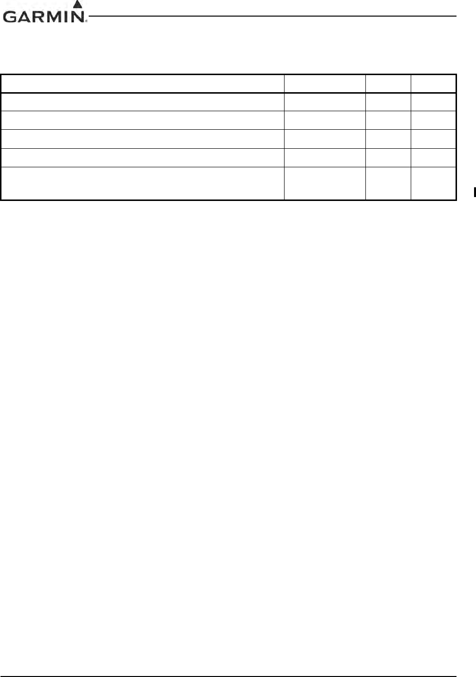
GIA 63 Installation Manual 190-00303-05
Page 4-26 Rev. V
4.6.2.4 Digital Audio
When interfaced to a compatible Garmin GMA series audio panel, these can be used in place of analog
audio lines. In dual GMA installations the CROSS-SIDE COM MIC DIGITAL AUDIO IN allows a
working GMA to access digital audio from both GIAs in the case of a single GMA failure.
Table 4-20. Digital Audio
Pin Name Connector Pin I/O
COM DIGITAL AUDIO OUT P601 13 Out
ON-SIDE COM MIC DIGITAL AUDIO IN P601 14 In
VOICE ALERT DIGITAL AUDIO OUT P603 69 Out
VOR/LOC DIGITAL AUDIO OUT P602 59 Out
CROSS-SIDE COM MIC DIGITAL AUDIO IN
(011-01105-2X/-3X/-4X ONLY) P601 18 In
DRAFT
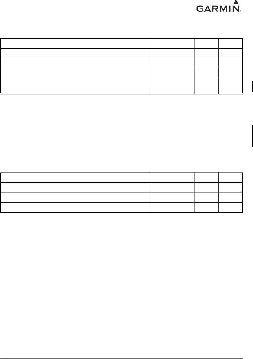
190-00303-05 GIA 63 Installation Manual
Rev. V Page 4-27
4.6.2.5 Discrete Inputs
INACTIVE: 10 ≤ Vin ≤ 33VDC or Rin ≥ 100kΩ
ACTIVE: Vin ≤ 1.9VDC with ≥ 75 uA sink current, or Rin ≤ 375Ω
Sink current is internally limited to 200 uA max for a grounded input
The COM REMOTE TRANSFER* input behavior is dependent on the COM software version and system
configurations (refer to Section 4.6.1).
VOR/ILS REMOTE TRANSFER* is a momentary input.
4.6.2.6 Marker Beacon
Active high inputs used for outer/middle/inner marker lamp inputs.
Table 4-21. Discrete Inputs
Pin Name Connector Pin I/O
TRANSMIT INTERLOCK* P601 11 In
COMM REMOTE TRANSFER* P601 12 In
VOR/ILS REMOTE TRANSFER* P602 28 In
COM SECONDARY TX INTERLOCK*
(011-01105-4X ONLY) P601 34 In
Table 4-22. Marker Beacon
Pin Name Connector Pin I/O
OUTER MARKER LAMP IN P605 56 In
MIDDLE MARKER LAMP IN P605 57 In
AIRWAY/INNER MARKER LAMP IN P605 58 In
DRAFT
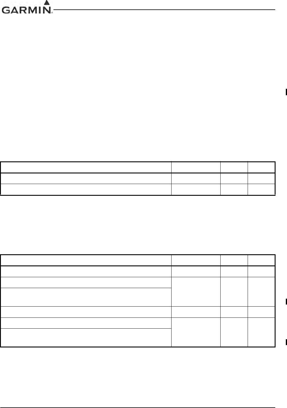
GIA 63 Installation Manual 190-00303-05
Page 4-28 Rev. V
4.7 VOR/ILS Indicator
4.7.1 VOR/ILS Indicator Function
The VOR/ILS indicator displays both lateral and vertical, To/From indications, lateral flags, vertical flags,
and superflags.
VOR/LOC COMPOSITE OUT is a standard VOR/localizer composite signal which may be used to drive
the Left/Right, TO/FROM, and Flag indications of certain navigational indicators that contain an internal
converter.
GLIDESLOPE COMPOSITE OUT (011-01105-2X/-3X/-4X ONLY) is a standard glideslope composite
signal which may be used to drive UP/DOWN and Flag indications of certain navigational indicators that
contain an internal converter.
The ILS ENERGIZE* output goes low when the VLOC frequency is channeled to a localizer channel.
4.7.2 VOR/ILS Indicator Electrical Characteristics
4.7.2.1 Superflags
The output supplies not less than 500 mA on a 28 volt system with the output voltage not less than
(AIRCRAFT POWER – 1.5 VDC) when the flag is to be OUT OF VIEW. The output voltage with respect
to ground is less than 0.25 VDC when the flag is to be IN VIEW.
4.7.2.2 Deviation
The deviation outputs are each capable of driving up to three 1000 Ω meter loads with ±150 mVDC ±10%
with respect to 2.5V Common for full-scale deflection. The drive circuit provides for more than full-scale
deflection with a maximum course deviation output voltage of ±300 mVDC ±10%.
Table 4-23. Superflags
Pin Name Connector Pin I/O
VOR/LOC SUPERFLAG P602 15 Out
GLIDESLOPE SUPERFLAG P602 38 Out
Table 4-24. Deviation
Pin Name Connector Pin I/O
VOR/LOC +LEFT P602 5Out
VOR/LOC +RIGHT (VOR/LOC COMMON)
P602 6Out
VOR/LOC +RIGHT (NAV COMMON)
(011-01105-2X/-3X/-4X ONLY)
GLIDESLOPE +UP P602 34 Out
GLIDESLOPE +DOWN (GLIDESLOPE COMMON)
P602 55 Out
GLIDESLOPE +DOWN (NAV COMMON)
(011-01105-2X/-3X/-4X ONLY)
DRAFT
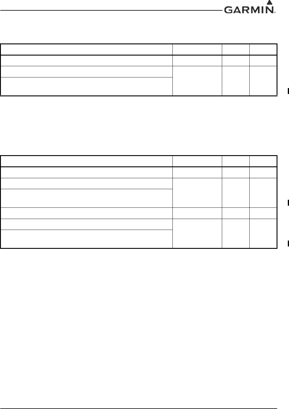
190-00303-05 GIA 63 Installation Manual
Rev. V Page 4-29
4.7.2.3 To/From
The output is capable of driving up to three 200 Ω meter loads. When indicating TO, the output is
+225 ±75 mVDC. When indicating FROM, output is -225 ±75 mVDC. When invalid information is
present (Flag IN VIEW) the TO/FROM output is 0 ±10 mVDC.
4.7.2.4 Flag
The Flag output is capable of driving up to three 1000 Ω meter loads. When valid information is present
(Flag OUT OF VIEW) the Flag output is 375 ±80 mVDC. When invalid information is present (Flag IN
VIEW) the Flag output is 0 ±25 mVDC.
Table 4-25. To/From
Pin Name Connector Pin I/O
VOR/LOC +TO P602 1Out
VOR/LOC +FROM (VOR/LOC COMMON)
P602 2Out
VOR/LOC +FROM (NAV COMMON)
(011-01105-2X/-3X/-4X ONLY)
Table 4-26. Flag
Pin Name Connector Pin I/O
VOR/LOC +FLAG P602 3Out
VOR/LOC -FLAG (VOR/LOC COMMON)
P602 4Out
VOR/LOC -FLAG (NAV COMMON)
(011-01105-2X/-3X/-4X ONLY)
GLIDESLOPE +FLAG P602 32 Out
GLIDESLOPE -FLAG (GLIDESLOPE COMMON)
P602 53 Out
GLIDESLOPE –FLAG (NAV COMMON)
(011-01105-2X/-3X/-4X ONLY)
DRAFT
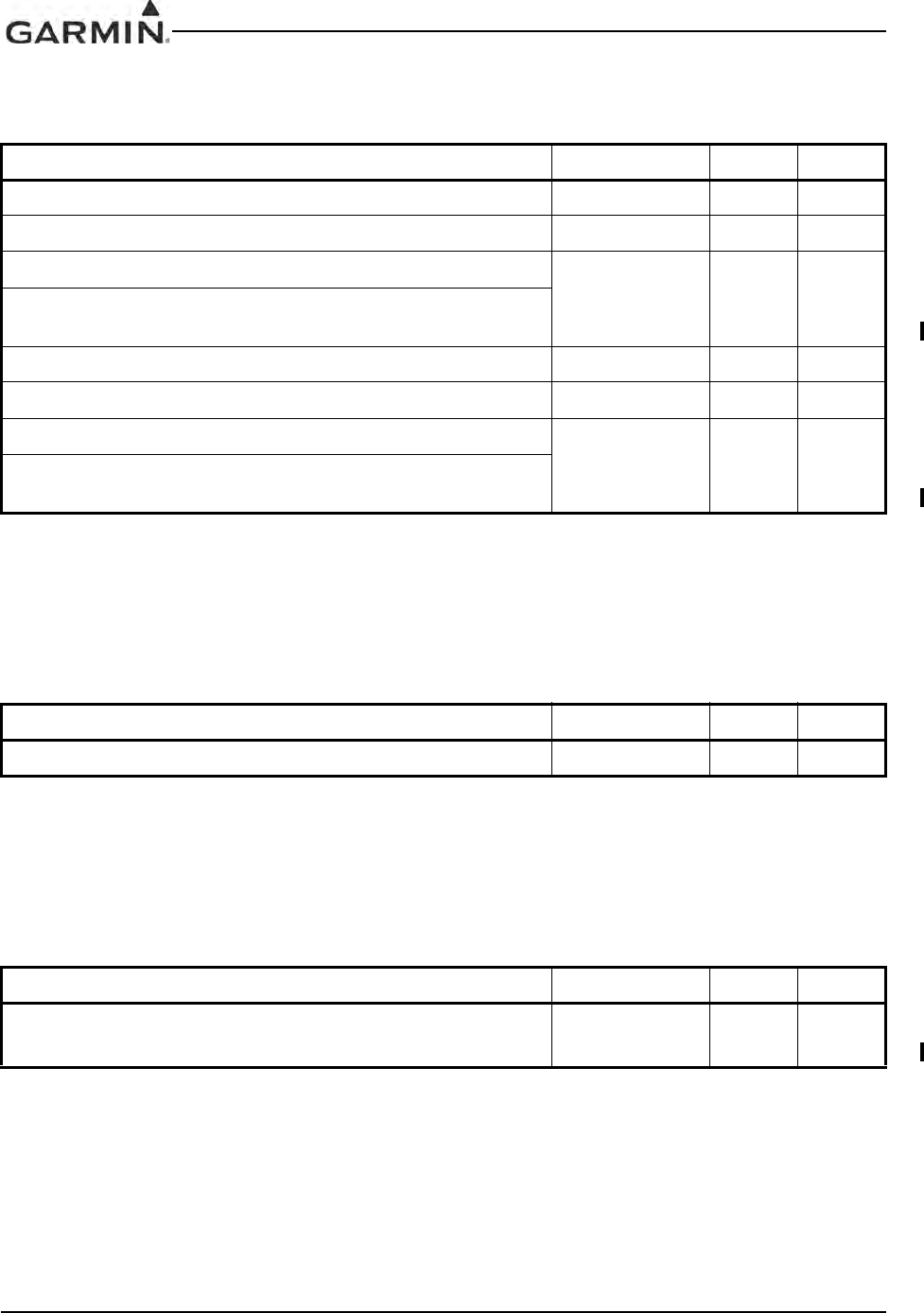
GIA 63 Installation Manual 190-00303-05
Page 4-30 Rev. V
4.7.2.5 OBS
VOR OBS ROTOR C and H are a buffered 500 Hz output that is intended to drive the OBS rotors. VOR
OBS STATOR D and VOR OBS STATOR F are each phase and amplitude shifted version of the VOR
ROTOR C output. Each pair is intended to read one of the two windings of the indicator’s OBS stator.
4.7.2.6 VOR/LOC Composite
With a Standard VOR Test Signal applied, VOR/LOC COMPOSITE OUT is 0.5 ±0.1 VRMS into a 10 kΩ
load. With a standard localizer centering test signal applied, VOR/LOC COMPOSITE OUT is 0.350 ±0.05
VRMS into a 10 kΩ load.
4.7.2.7 Glideslope Composite
With a standard glideslope centering test signal applied, GLIDESLOPE COMPOSITE OUT is
0.35 +/- 0.05 Vrms into a 10k Ω load.
Table 4-27. OBS
Pin Name Connector Pin I/O
VOR OBS ROTOR C P602 9Out
VOR OBS ROTOR H (GROUND) P602 10 --
VOR OBS STATOR E (VOR/LOC COMMON)
P602 11 Out
VOR OBS STATOR E (NAV COMMON)
(011-01105-2X/-3X/-4X ONLY)
VOR OBS STATOR F P602 12 In
VOR OBS STATOR D P602 13 In
VOR OBS STATOR G (VOR/LOC COMMON)
P602 14 Out
VOR OBS STATOR G (NAV COMMON)
(011-01105-2X/-3X/-4X ONLY)
Table 4-28. VOR/LOC Composite
Pin Name Connector Pin I/O
VOR/LOC COMPOSITE OUT P602 8Out
Table 4-29. Glideslope Composite
Pin Name Connector Pin I/O
GLIDESLOPE COMPOSITE OUT
(011-01105-2X/-3X/-4X ONLY) P602 58 Out
DRAFT

190-00303-05 GIA 63 Installation Manual
Rev. V Page 4-31
4.7.2.8 ILS Energize
INACTIVE: Floating (can be pulled up to externally sourced Vout in the range 0 ≤ Vout ≤ 33VDC)
Leakage current in the INACTIVE state is typically ≤ 10 uA to ground
ACTIVE: Vout ≤ 0.5VDC with ≤ 20 mA sink current
Sink current must be externally limited to 20 mA max
Table 4-30. ILS Energize
Pin Name Connector Pin I/O
ILS ENERGIZE* P602 29 Out
DRAFT
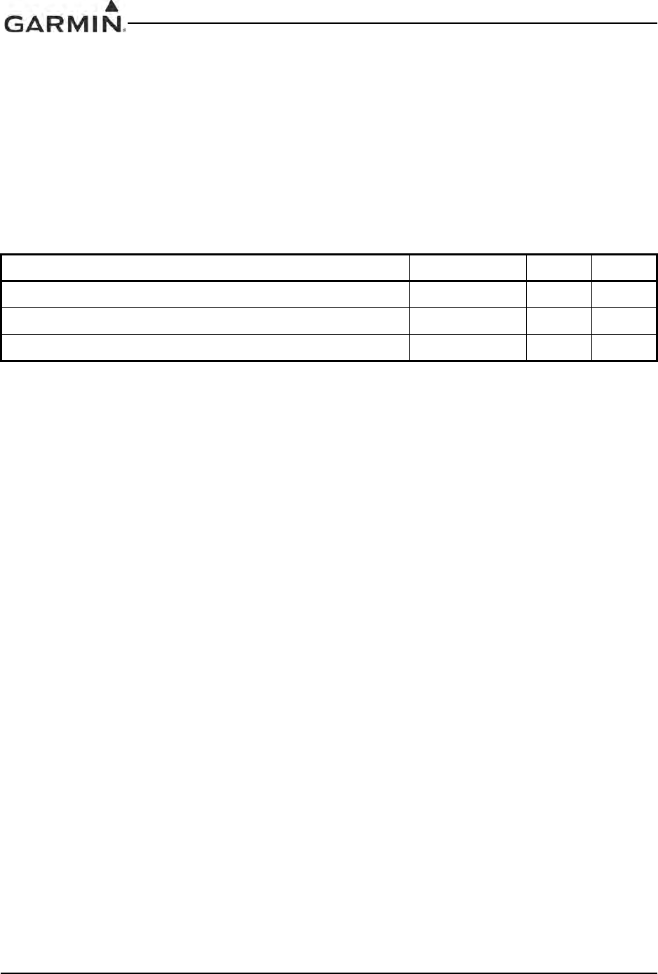
GIA 63 Installation Manual 190-00303-05
Page 4-32 Rev. V
4.8 RMI/OBI
4.8.1 RMI/OBI Function
The VOR OBI output provides bearing information from the active waypoint based upon the VOR
receiver.
When a localizer channel is tuned on the VLOC window, there is a bit in the data stream set to indicate that
a localizer frequency is tuned which stows the needle or drives it to the 3 o’clock position.
4.8.2 RMI/OBI Electrical Characteristics
INACTIVE: Floating (can be pulled up to externally sourced Vout in the range 0 ≤ Vout ≤ 33VDC)
Leakage current in the INACTIVE state is typically ≤ 10 uA to ground
ACTIVE: Vout ≤ 0.5VDC with ≤ ?20 mA sink current
Sink current must be externally limited to 20 mA max
Table 4-31. RMI/OBI
Pin Name Connector Pin I/O
VOR OBI CLOCK P602 25 Out
VOR OBI SYNC P602 26 Out
VOR OBI DATA P602 27 Out
DRAFT
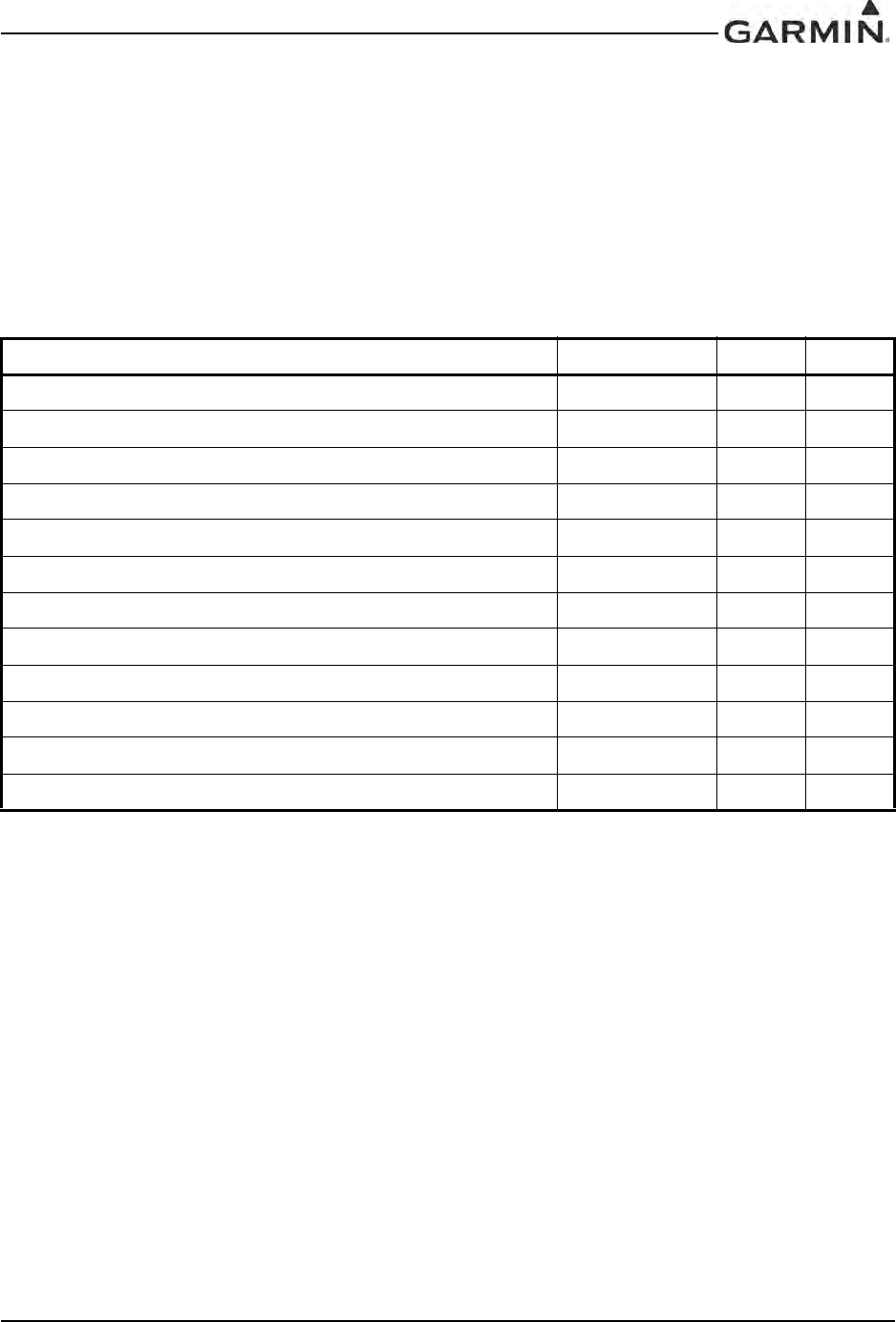
190-00303-05 GIA 63 Installation Manual
Rev. V Page 4-33
4.9 DME Tuning and ADF
4.9.1 DME Tuning Function
The GIA 63(X) can channel a DME based on the tuned VLOC frequency. The GIA 63(X) outputs 2 of 5,
BCD or Slip parallel DME and King Serial DME channeling format. When DME COMMON is held low,
the GIA 63(X) actively tunes the DME.
4.9.2 DME Interface and ADF Electrical Characteristics
4.9.2.1 Parallel DME Tuning
For each of the parallel DME tuning discrete outputs:
INACTIVE: Floating (can be pulled up to externally sourced Vout in the range 0 ≤ Vout ≤ 33VDC)
Leakage current in the INACTIVE state is typically ≤ 10 uA to ground
ACTIVE: Vout ≤ 0.5VDC with ≤ 20 mA sink current
Sink current must be externally limited to 20 mA max
NAV DME COMMON must be pulled low to indicate to the NAV module that it is the device channeling
the DME.
INACTIVE: 10 ≤ Vin ≤ 33VDC or Rin ≥ 100kΩ
ACTIVE: Vin ≤ 1.9VDC with ≥ 75 uA sink current, or Rin ≤ 375Ω
Sink current is internally limited to 200 uA max for a grounded input
Table 4-32. Parallel DME Tuning
Pin Name Connector Pin I/O
PARALLEL DME 1 MHZ-D P602 33 Out
PARALLEL DME 100 KHZ-A P602 37 Out
PARALLEL DME 100 KHZ-B P602 39 Out
PARALLEL DME 100 KHZ-C P602 40 Out
PARALLEL DME 100 KHZ-D P602 42 Out
PARALLEL DME 50 KHZ P602 43 Out
PARALLEL DME 1 MHZ-A P602 45 Out
PARALLEL DME 1 MHZ-B P602 46 Out
PARALLEL DME 1 MHZ-C P602 47 Out
PARALLEL DME 100KHZ-E P602 54 Out
PARALLEL DME 1MHZ-E P602 56 Out
NAV DME COMMON P602 41 In
DRAFT
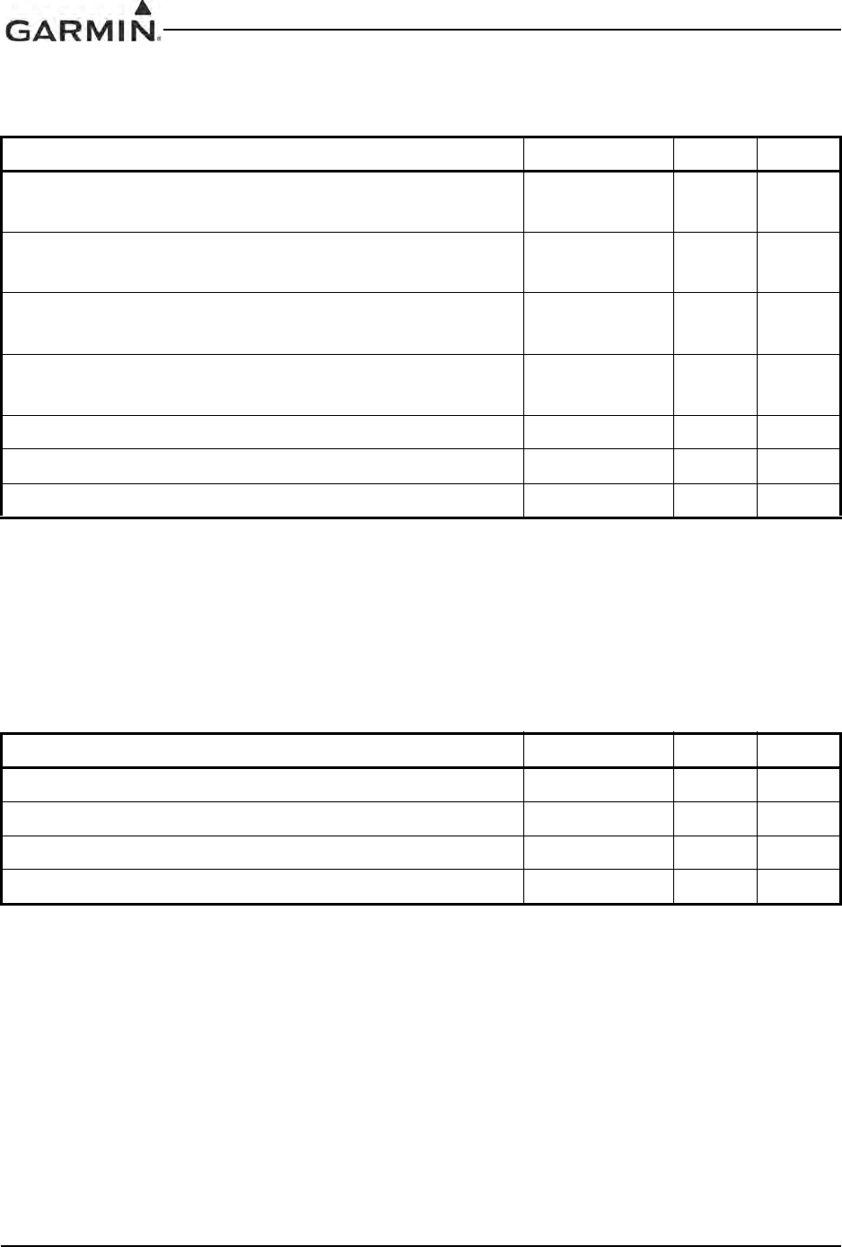
GIA 63 Installation Manual 190-00303-05
Page 4-34 Rev. V
4.9.2.2 King Serial DME Interface
These pins are used when the GIA 63(X) is configured for King Serial DME tuning.
Input logic levels are:
High 6.5 Vdc or greater
Low 3.5 Vdc or less
4.9.2.3 Automatic Direction Finder Inputs
Table 4-33. King Serial DME Interface
Pin Name Connector Pin I/O
KING SERIAL DME CLOCK
(011-00781-0X AND 011-01105-0X ONLY) P602 18 Out
KING SERIAL DME DATA
(011-00781-0X AND 011-01105-0X ONLY) P602 19 Out
KING SERIAL RNAV REQUEST
(011-00781-0X AND 011-01105-0X ONLY) P602 20 In
KING SERIAL RNAV* MODE
(011-00781-0X AND 011-01105-0X ONLY) P602 21 In
MAIN KING SERIAL DME DATA P606 56 I/O
MAIN KING SERIAL DME CLOCK P606 60 I/O
MAIN KING SERIAL DME REQUEST P606 62 Out
Table 4-34. Automatic Direction Finder Inputs
Pin Name Connector Pin I/O
ADF X/COS P606 10 In
ADF Y/SIN P606 11 In
ADF Z (GROUND) P606 12 --
ADF DC REF IN P606 32 In
DC
Amplitude: -8 Vdc to +8 Vdc
Input Impedance: > 80 kΩ
Range: 0 to 360 degrees
Resolution: ±0.1 degree or better
Accuracy: ±3.0 degrees
DC Reference Input: 0 to 5 Vdc maximum (>40 kΩ)
DRAFT
190-00303-05 GIA 63 Installation Manual
Rev. V Page 4-35
4.10 Auto Pilot
4.10.1 Flight Instruments
Inputs from AFCS that direct the pilot through the PFD.
The input voltage is positive if FLIGHT DIRECTOR PITCH +UP is greater than FLIGHT DIRECTOR
PITCH +DOWN. Otherwise the input voltage is negative.
The input voltage is positive if FLIGHT DIRECTOR ROLL +RIGHT is greater than FLIGHT
DIRECTOR ROLL +LEFT. Otherwise the input voltage is negative.
Table 4-35. Flight Instruments
Pin Name Connector Pin I/O
FLIGHT DIRECTOR PITCH +UP P605 8In
FLIGHT DIRECTOR PITCH +DOWN P605 9In
FLIGHT DIRECTOR ROLL +RIGHT P605 10 In
FLIGHT DIRECTOR ROLL +LEFT P605 11 In
Flight Director Pitch +UP/+DOWN Flight Director Roll +RIGHT/+LEFT
Amplitude -1.0 Vdc to +1.25 Vdc -1.0 Vdc to +1.0 Vdc
Input 19 kOhm differential 19 kOhm differential
Impedance 26 kOhm to ground 26 kOhm to ground
Range Limit 10 degrees down and 15 degrees up +/- 20 degrees
Resolution 0.7mV 0.7mV
Accuracy +/-13mV with an input voltage of 0V +/-17mV with an input voltage of 0V
+/-63mV with an input voltage of +/-1.25V +/-83mV with an input voltage of +/-1.25V
DRAFT
GIA 63 Installation Manual 190-00303-05
Page 4-36 Rev. V
4.10.2 Automatic Flight Control System Outputs
Variable-amplitude output, which is proportional to the aircraft roll command from the GPS navigation
system.
Outputs heading datum information to AFCS.
Table 4-36. Analog Roll Steering
Pin Name Connector Pin I/O
ANALOG ROLL STEERING HI P606 34 Out
ANALOG ROLL STEERING LO (GROUND) P606 36 --
DC
Amplitude: -15 to +15 Vdc
Load Impedance: > 5 kΩ
Scaling: 2.0 Vdc per degree of roll command
Range: 0 ± 7.5 degrees of roll
Resolution: ± 0.05° or better
Accuracy: ± 0.3°
Table 4-37. Heading Datum
Pin Name Connector Pin I/O
HEADING DATUM HI P606 46 Out
HEADING DATUM LO (GROUND) P606 47 --
DC
Amplitude: -15 to +15 Vdc
Load Impedance: > 5 kΩ
Scaling: 0.55 Vdc per degree of heading error
Range: 0 ± 27 degrees
Resolution: ± 0.15° or better
Accuracy: ± 1°
DRAFT

190-00303-05 GIA 63 Installation Manual
Rev. V Page 4-37
Outputs course datum information to AFCS.
Table 4-38. Course Datum
Pin Name Connector Pin I/O
COURSE DATUM HI P606 48 Out
COURSE DATUM LO (GROUND) P606 49 --
DC
Amplitude: -15 to +15 Vdc
Load Impedance: > 5 kΩ
Scaling: 0.21 Vdc per degree of course error
Range: 0 ± 71 degrees
Resolution: ± 0.15° or better
Accuracy: ± 1°
DRAFT
GIA 63 Installation Manual 190-00303-05
Page 4-38 Rev. V
4.10.3 Main Deviation Outputs
The deviation output is capable of driving up to three 1000 Ω loads with ±150 mVDC ±5% for full-scale
deflection. The drive circuit provides for more than full-scale deflection with a maximum course deviation
output voltage of ±300 mVDC ±5%.
The Flag output is capable of driving up to three 1000 Ω loads. When valid information is present (Flag
OUT OF VIEW) the Flag output is 375 ±80 mVDC. When invalid information is present (Flag IN VIEW)
the Flag output is 0 ±25 mVDC.
The output supplies not less than 500 mA on a 28 volt system with the output voltage not less than
(AIRCRAFT POWER –2.0 VDC) when the flag is to be OUT OF VIEW. The output voltage with respect to
ground is less than 0.25 VDC when the flag is to be IN VIEW.
Table 4-39. Main Lateral and Vertical Deviation
Pin Name Connector Pin I/O
MAIN LATERAL DEVIATION +LEFT P605 17 Out
MAIN LATERAL DEVIATION +RIGHT (MAIN COMMON) P605 18 Out
MAIN VERTICAL DEVIATION +UP P605 23 Out
MAIN VERTICAL DEVIATION +DOWN (MAIN COMMON) P605 24 Out
Table 4-40. Main Lateral and Vertical Flag
Pin Name Connector Pin I/O
MAIN LATERAL +FLAG P605 19 Out
MAIN LATERAL -FLAG (MAIN COMMON) P605 20 Out
MAIN VERTICAL +FLAG P605 25 Out
MAIN VERTICAL –FLAG (MAIN COMMON) P605 26 Out
Table 4-41. Superflag
Pin Name Connector Pin I/O
MAIN LATERAL SUPERFLAG P605 62 Out
MAIN VERTICAL SUPERFLAG P605 63 Out
SUPERFLAG 1A P605 67 Out
SUPERFLAG 2A P605 75 Out
SUPERFLAG 3A P605 77 Out
SUPERFLAG 4A P605 64 Out
DRAFT

190-00303-05 GIA 63 Installation Manual
Rev. V Page 4-39
4.10.4 Remote Annunciate Data Bus
These inputs read the remote annunciate data bus that the autopilot uses to tell its remote annunciator panel
what mode it is operating in.
The GIA 63 requires 4.7 kΩ pull-up resistors to +28 VDC in the aircraft harness for each of these inputs. No
pull-up resistors are required for the GIA 63W or GIA 63H.
NOTE
The GIA 63W and GIA 63H will function properly if the pull-up resistors are installed in
the aircraft harness.
Table 4-42. Remote Annunciate Data Bus
Pin Name Connector Pin I/O
REMOTE ANNUNCIATE CLOCK P606 53 In
REMOTE ANNUNCIATE DATA P606 54 In
REMOTE ANNUNCIATE SYNC P606 55 In
DRAFT

GIA 63 Installation Manual 190-00303-05
Page 4-40 Rev. V
This page intentionally left blank
DRAFT
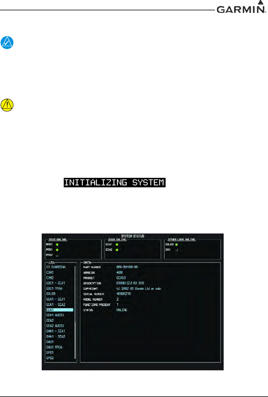
190-00303-05 GIA 63 Installation Manual
Rev. W Page A-1
APPENDIX A GIA 63 MAIN BOOT BLOCK UPLOADING INSTRUCTIONS
NOTE
This appendix applies to the GIA 63 only, and does not apply to the GIA 63W or GIA 63H.
A.1 Introduction
This appendix contains instructions on how to upgrade main boot block software for the GIA 63. Boot
block version 4.01 is required for GIA Main Software Version 4.00 or later.
CAUTION
While performing this procedure ensure the aircraft is connected to and drawing power
from a power cart. A loss of power during this procedure may result in a defective GIA 63.
A.2 Determining Current Boot Block
1. Ensure the G1000 is powered off.
2. Insert the airframe specific approved software loader card (containing GIA main software version
4.00 or later) into the top slot of the PFD.
3. While holding the ENT key on the PFD, restore power to the PFD.
4. When the words appear in the upper left corner of the
PFD, release the ENT key.
5. Press the CLR key at the “DO YOU WANT TO UPDATE SYSTEM FILED?” prompt.
6. Repeat step 3 and 4 for the MFD.
7. Restore power to all remaining G1000 LRUs.
8. On the MFD use the FMS knob to highlight ‘GIA 1’ on the System Status page.
Figure A-1. System Status Page
DRAFT
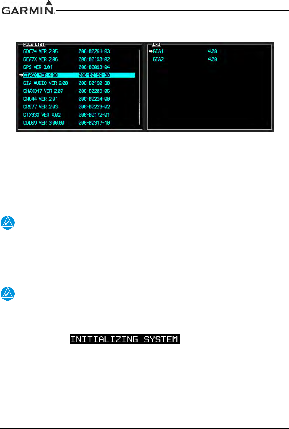
GIA 63 Installation Manual 190-00303-05
Page A-2 Rev. W
9. On the PFD use the FMS knob to turn to the Software Upload page.
10. Use the FMS knob to highlight GIA 6X software.
Figure A-2. GIA 6X Software
11. Press the LRU softkey and highlight ‘GIA 1’.
12. Press the ENT key to begin loading software.
13. The boot block version should now appear on the MFD.
14. If GIA main boot block version is 4.00 or earlier press the CANCEL softkey on the PFD and select
‘YES’ at the prompt. Continue to Section A.3 for instructions on loading GIA main boot block
version 4.01.
NOTE
If GIA main boot block version is 4.01, do not cancel the software upload.
15. Repeat steps 7 through 13 for GIA 2.
A.3 Loading Boot Block Version 4.01
1. Remove power from the PFD only.
NOTE
If power is removed from the entire G1000 system GIA 2 may appear as GIA 1.
2. Insert the GIA 63 boot block version 4.01 loader card into the top slot of the PFD.
3. While holding the ENT key on the PFD, restore power to the PFD.
4. When the words appear in the upper left corner of the
PFD, release the ENT key.
5. Use the FMS knob to turn to the Software Upload page on the PFD.
6. Verify ‘GIA 6X Boot Block 4.01’ appears in the File List.
7. Verify ‘GIA 1’ and ‘GIA 2’ appears in the LRU window.
8. Press the FMS knob to highlight ‘GIA 6X Boot Block 4.01’.
9. Press the LOAD softkey.
10. Press the ENT key at the “BEGIN FILE UPLOAD?” prompt.
DRAFT
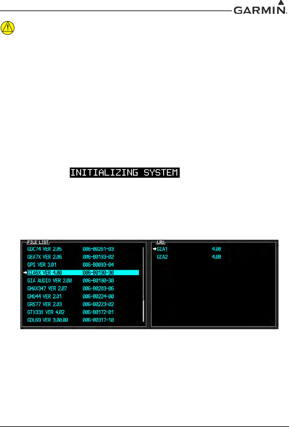
190-00303-05 GIA 63 Installation Manual
Rev. W Page A-3
CAUTION
Do not turn power off or cancel the software upload while the boot block is loading.
11. Confirm update completion and press the ENT key.
12. On the MFD use the FMS knob to turn to the System Status page.
13. Highlight ‘GIA 1’.
14. Verify ‘G1000 GIA 6X SYS’ is being reported in the description field.
15. Power down the G1000.
16. Remove the GIA 63 boot block version 4.01 loader card form the PFD.
17. Continue to Section A.4.
A.4 Loading GIA Main Software (only if GIA main software was cancelled in
Section A.2)
1. Insert the airframe specific approved software loader card (containing GIA main software version
4.00 or later) into the top slot of the PFD.
2. While holding the ENT key on the PFD, restore power to the PFD.
3. When the words appear in the upper left corner of the
PFD, release the ENT key.
4. Press the CLR key at the “DO YOU WANT TO UPDATE SYSTEM FILES?” prompt.
5. Repeat step 2 and 3 for the MFD.
6. Restore power to all remaining G1000 LRUs.
7. On the PFD use the FMS knob to turn to the Software Upload page.
8. Use the FMS knob to highlight GIA 6X software.
Figure A-3. GIA 6X Software
9. Press the LOAD softkey.
10. Press the ENT key at the “BEGIN FILE UPLOAD?” prompt.
11. Confirm update completion and press the ENT key.
DRAFT

GIA 63 Installation Manual 190-00303-05
Page A-4 Rev. W
This page intentionally left blank
DRAFT
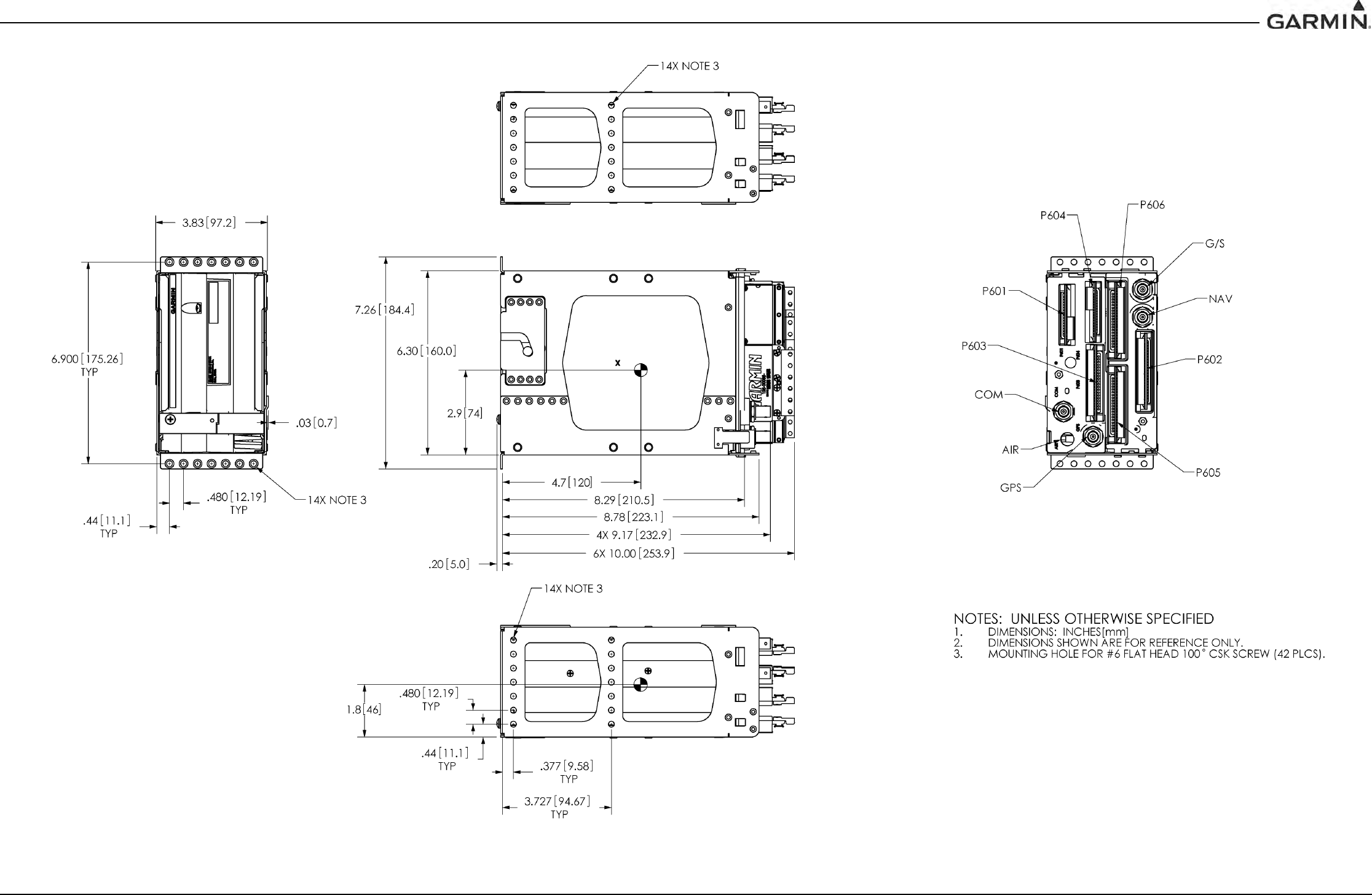
190-00303-05 GIA 63 Installation Manual
Rev. W Page B-1
APPENDIX B OUTLINE AND INSTALLATION DRAWINGS
Figure B-1. GIA 63(W) Modular Installation Outline Drawing
DRAFT
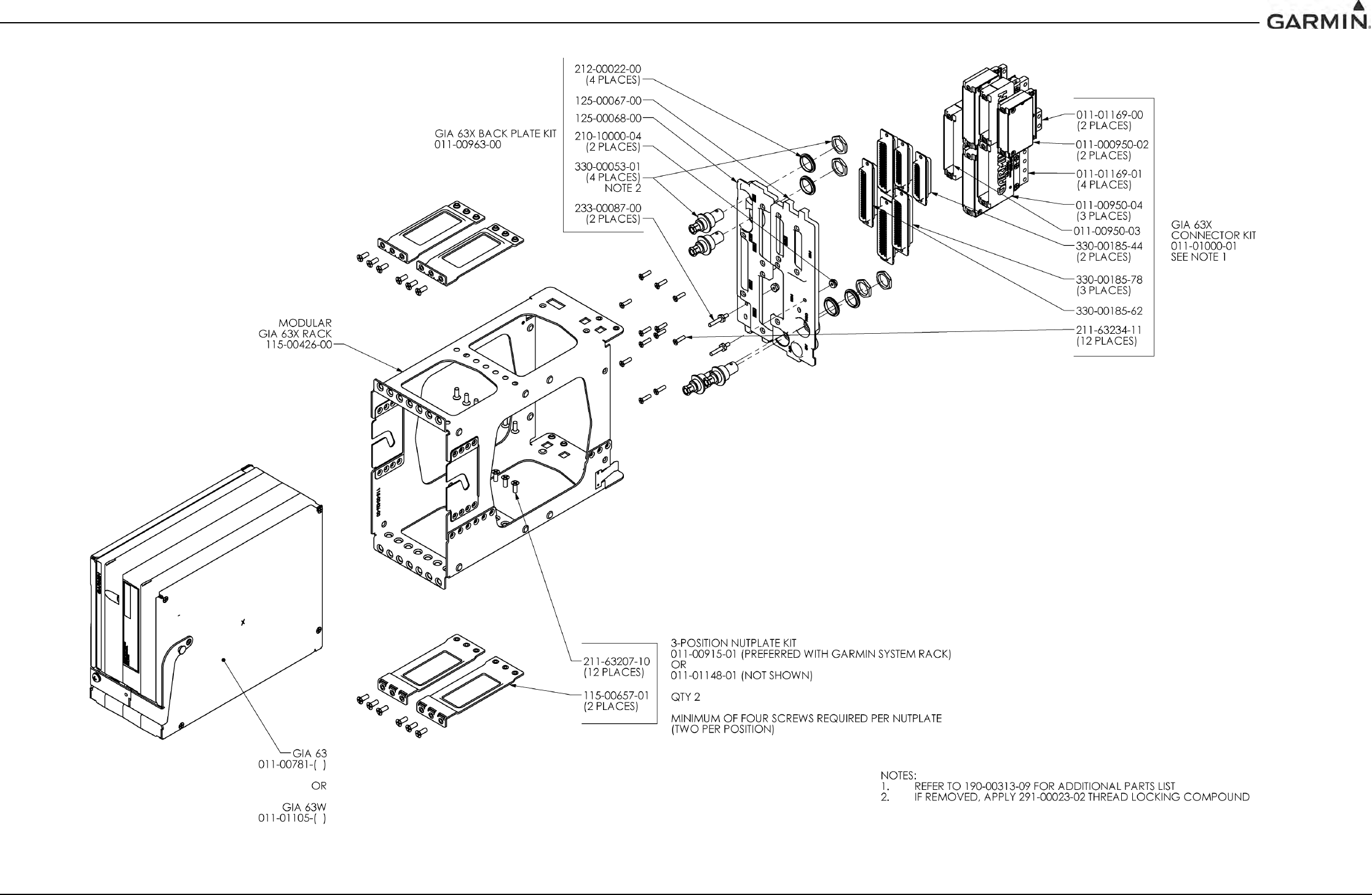
190-00303-05 GIA 63 Installation Manual
Rev. W Page B-2
APPENDIX B OUTLINE AND INSTALLATION DRAWINGS
Figure B-2. GIA 63(W) Modular Installation Drawing
DRAFT
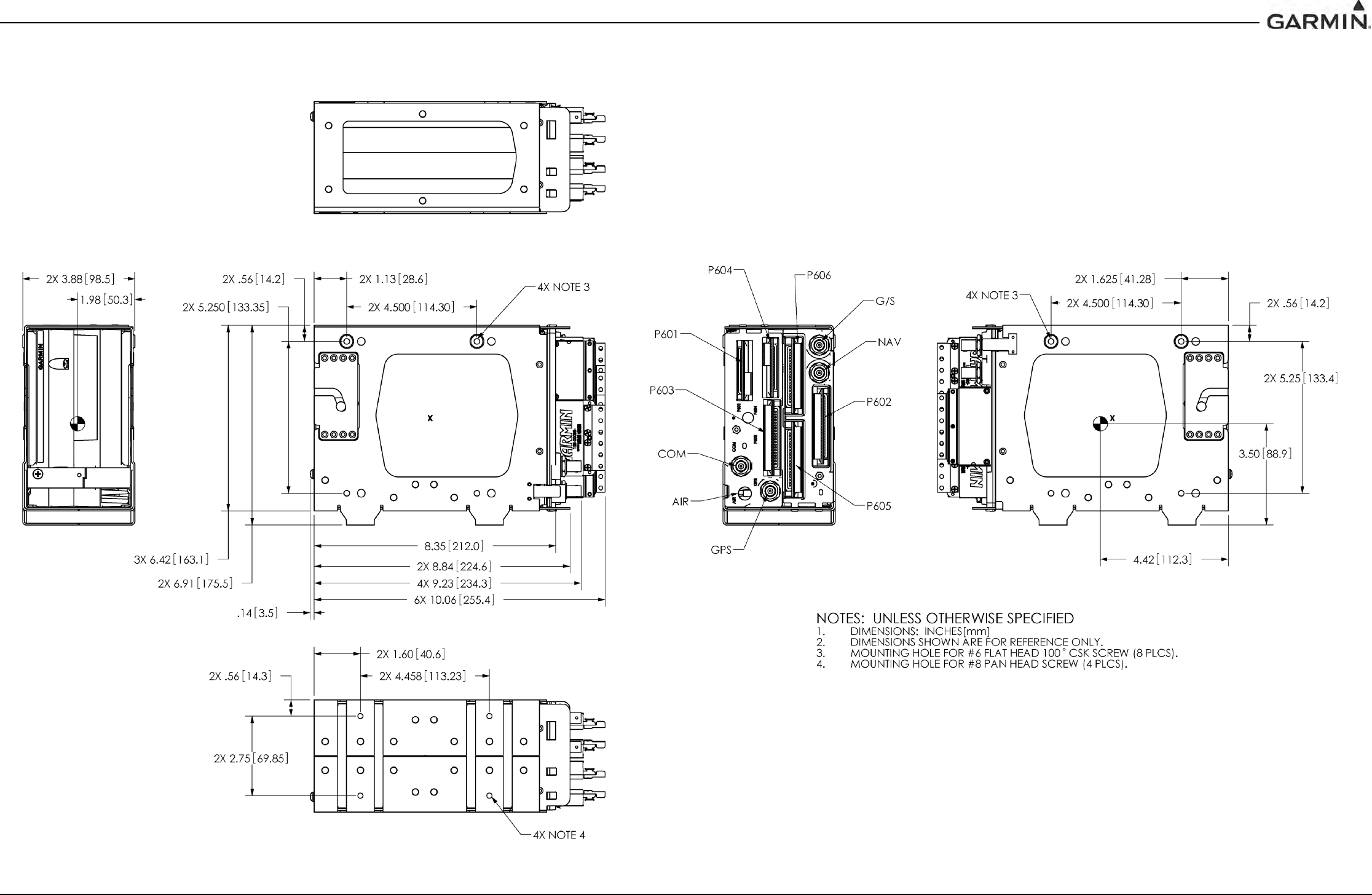
190-00303-05 GIA 63 Installation Manual
Rev. W Page B-3
APPENDIX B OUTLINE AND INSTALLATION DRAWINGS
Figure B-3. GIA 63(W) Standalone Installation Outline Drawing
DRAFT
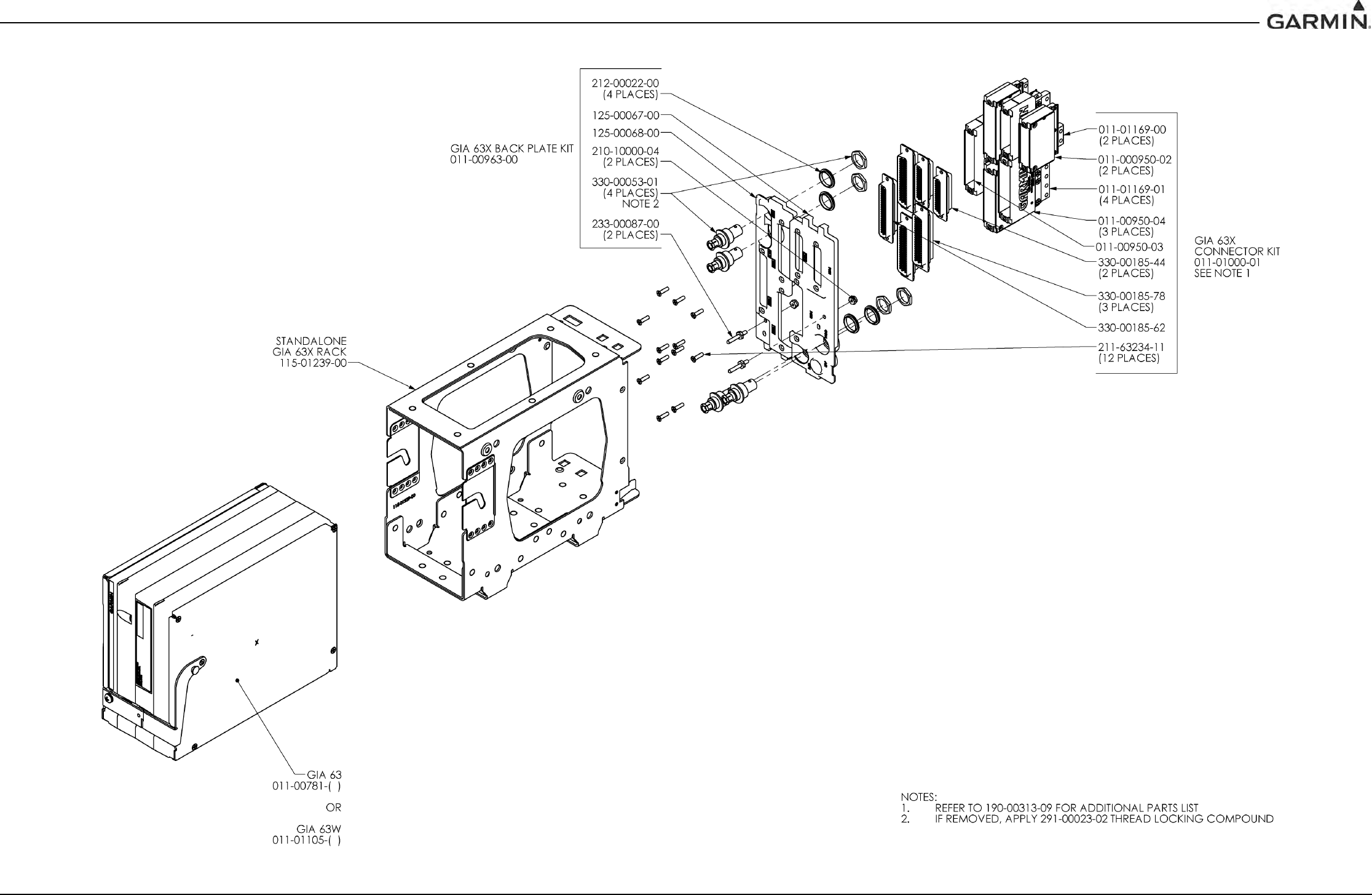
190-00303-05 GIA 63 Installation Manual
Rev. W Page B-4
APPENDIX B OUTLINE AND INSTALLATION DRAWINGS
Figure B-4. GIA 63(W) Standalone Installation Drawing
DRAFT
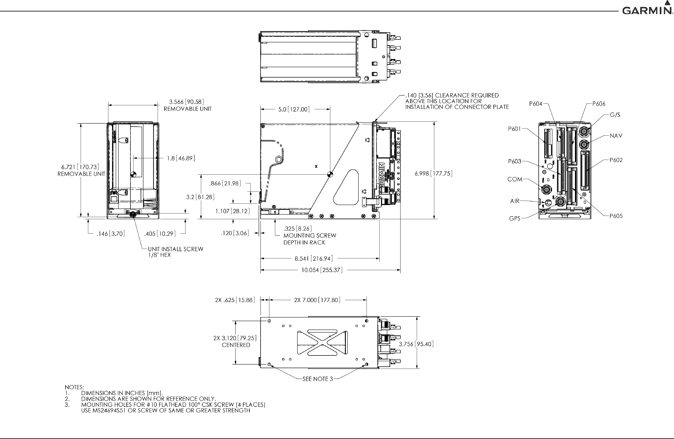
190-00303-05 GIA 63 Installation Manual
Rev. W Page B-5
APPENDIX B OUTLINE AND INSTALLATION DRAWINGS
Figure B-5. GIA 63H Standalone Installation Outline Drawing
DRAFT
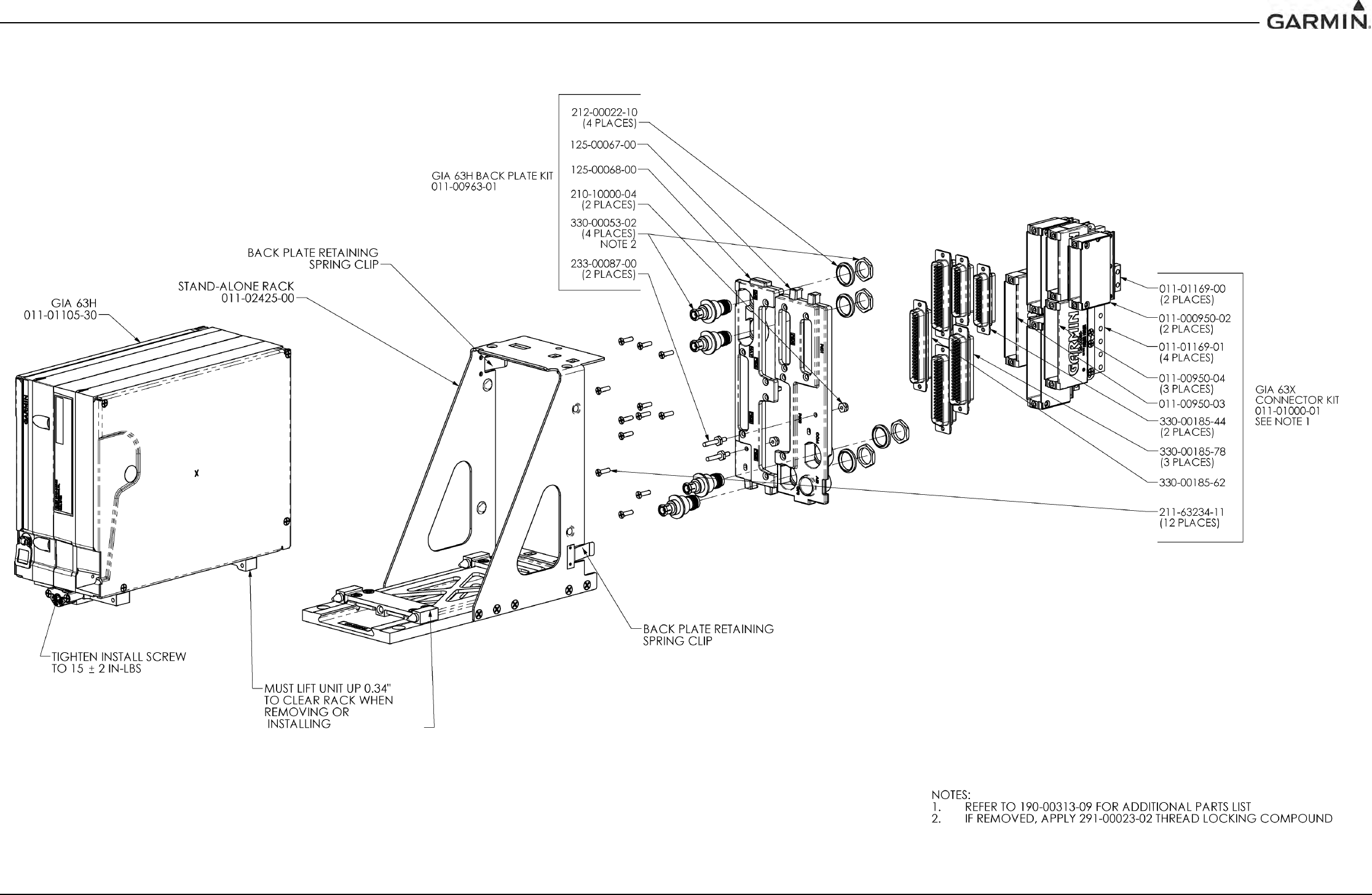
190-00303-05 GIA 63 Installation Manual
Rev. W Page B-6
APPENDIX B OUTLINE AND INSTALLATION DRAWINGS
Figure B-6. GIA 63H Standalone Installation Drawing
DRAFT
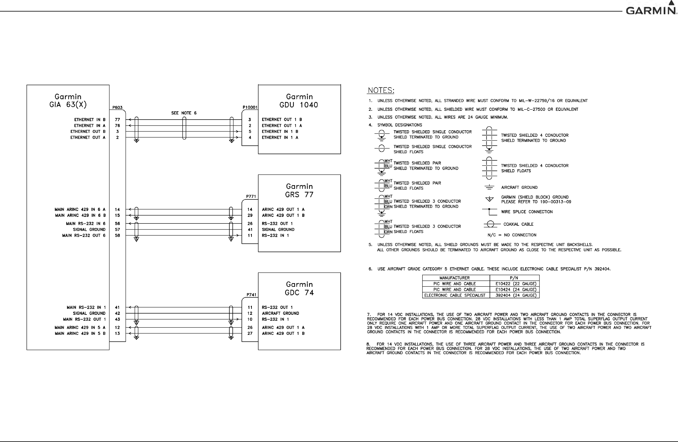
190-00303-05 GIA 63 Installation Manual
Rev. W Page C-1
APPENDIX C INTERCONNECT DRAWINGS
Figure C-1. GIA 63(X) Example Interconnect
DRAFT
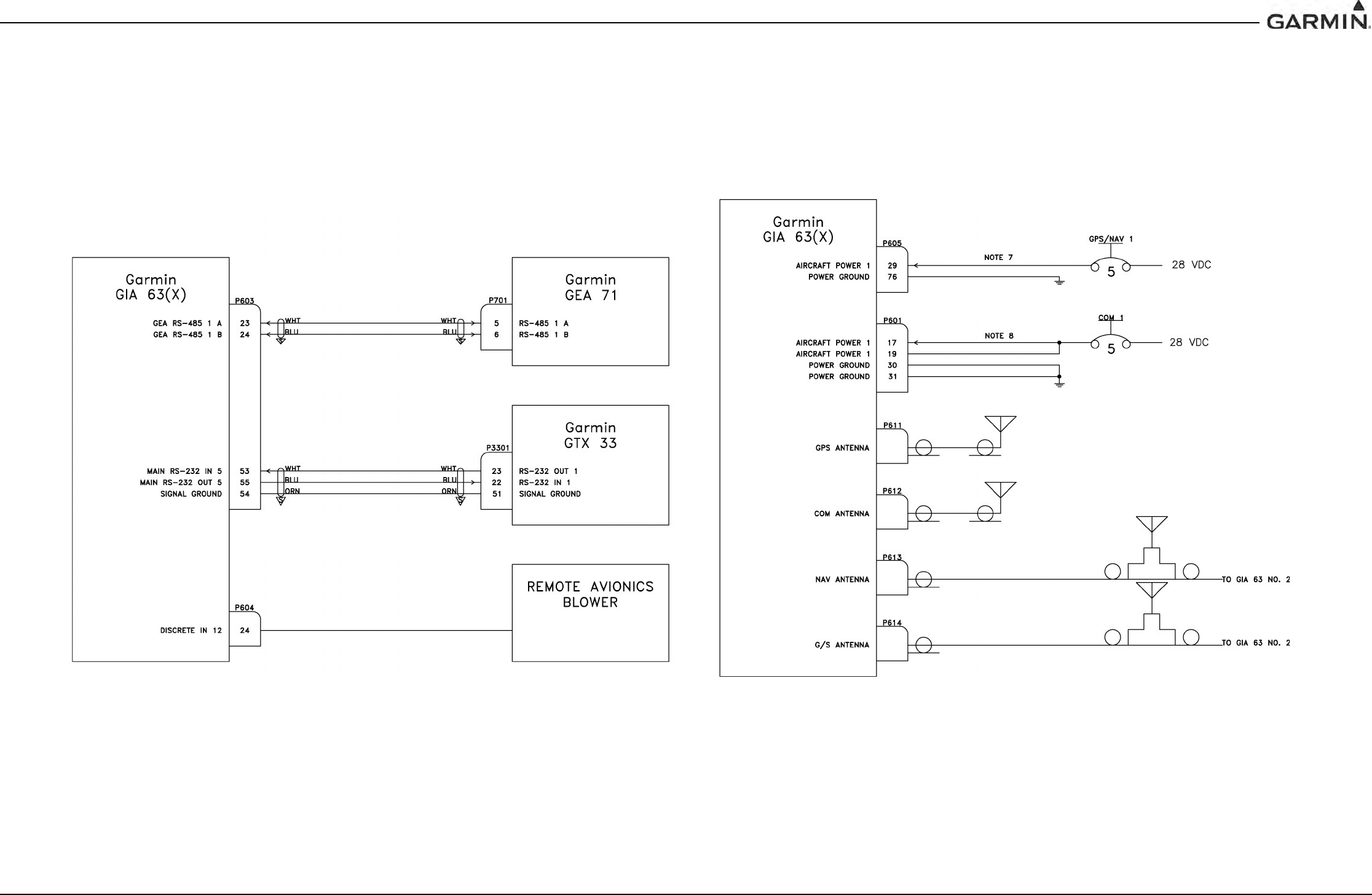
190-00303-05 GIA 63 Installation Manual
Rev. W Page C-2
APPENDIX C INTERCONNECT DRAWINGS
Figure C-2. GIA 63(X) Example Interconnect
DRAFT
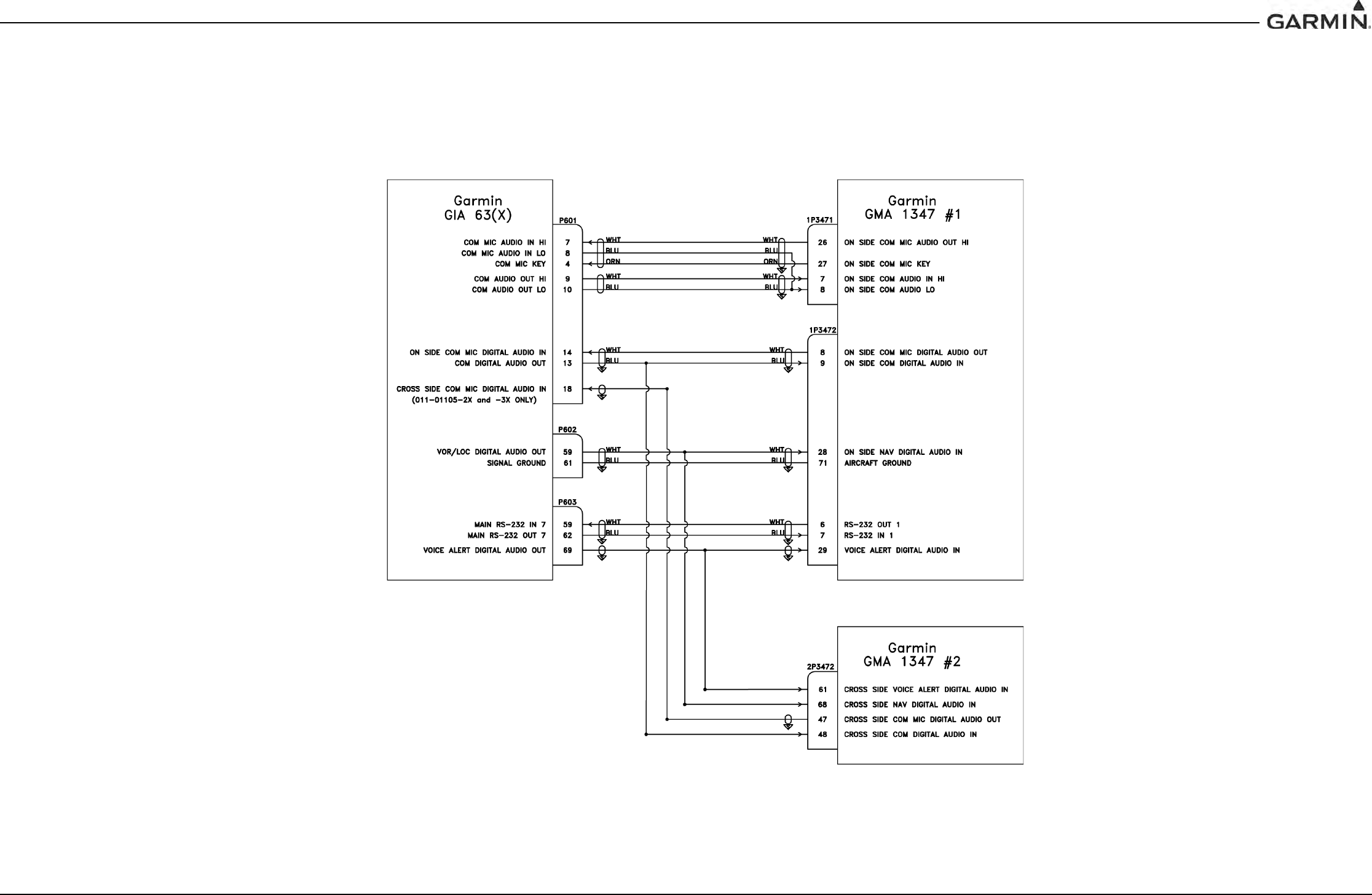
190-00303-05 GIA 63 Installation Manual
Rev. W Page C-3
APPENDIX C INTERCONNECT DRAWINGS
Figure C-3. GIA 63(X) Example Interconnect
DRAFT
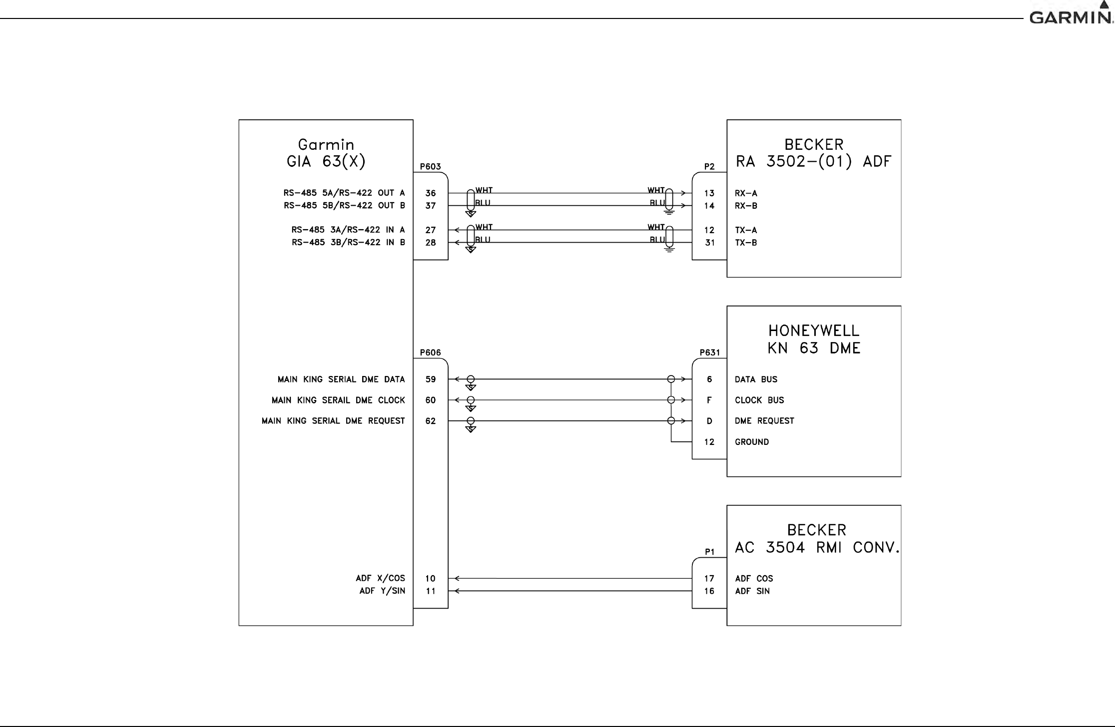
190-00303-05 GIA 63 Installation Manual
Rev. W Page C-4
APPENDIX C INTERCONNECT DRAWINGS
Figure C-4. GIA 63(X) Example Interconnect
DRAFT
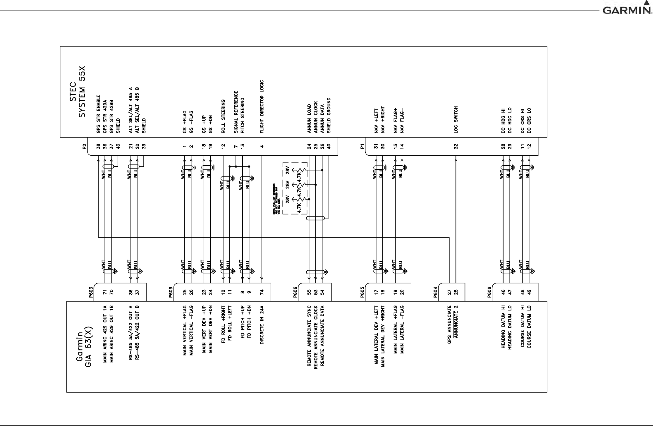
190-00303-05 GIA 63 Installation Manual
Rev. W Page C-5
APPENDIX C INTERCONNECT DRAWINGS
Figure C-5. GIA 63(X) Example Interconnect
DRAFT
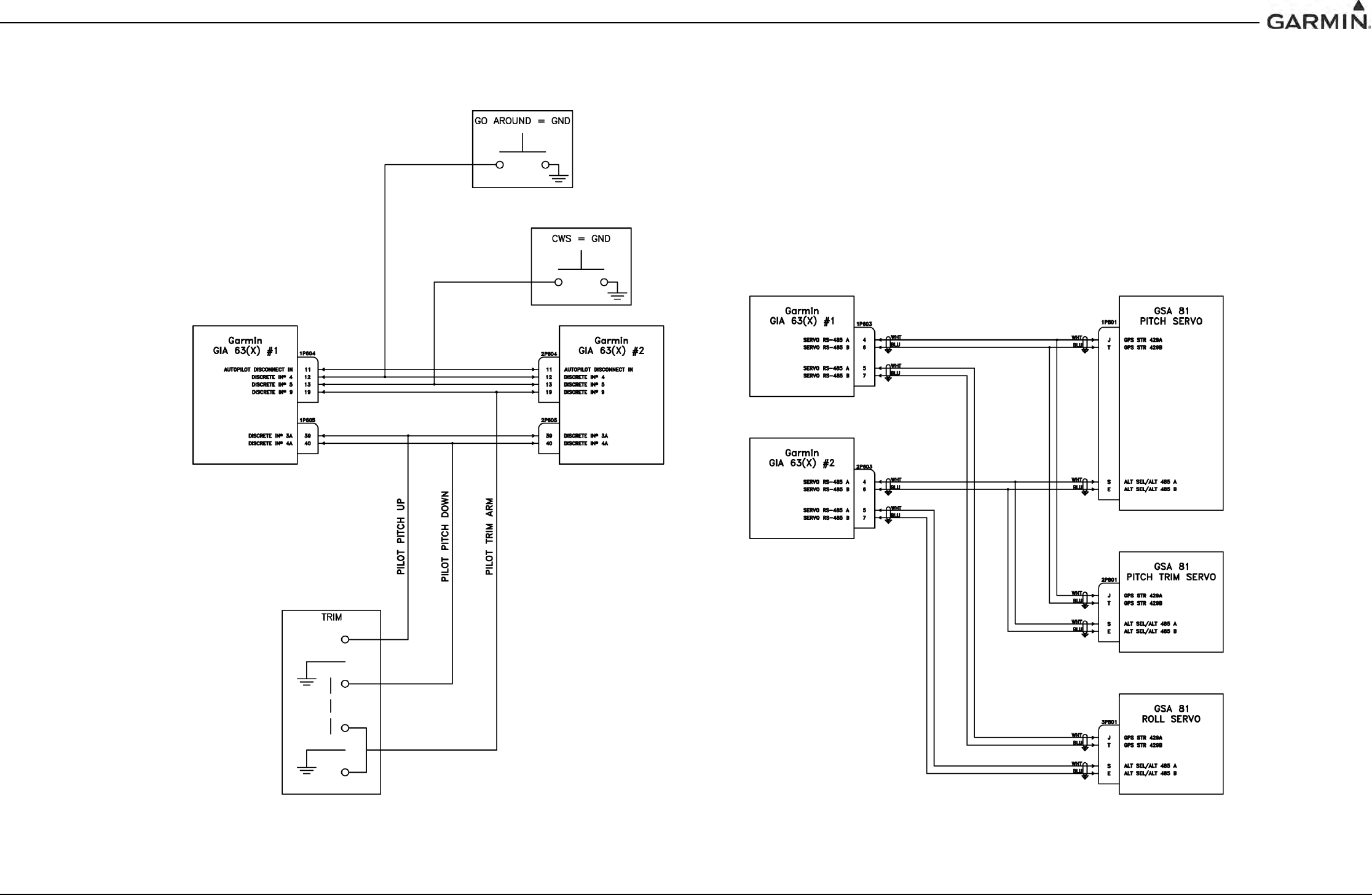
190-00303-05 GIA 63 Installation Manual
Rev. W Page C-6
APPENDIX C INTERCONNECT DRAWINGS
Figure C-6. GIA 63(X) Example Interconnect
DRAFT
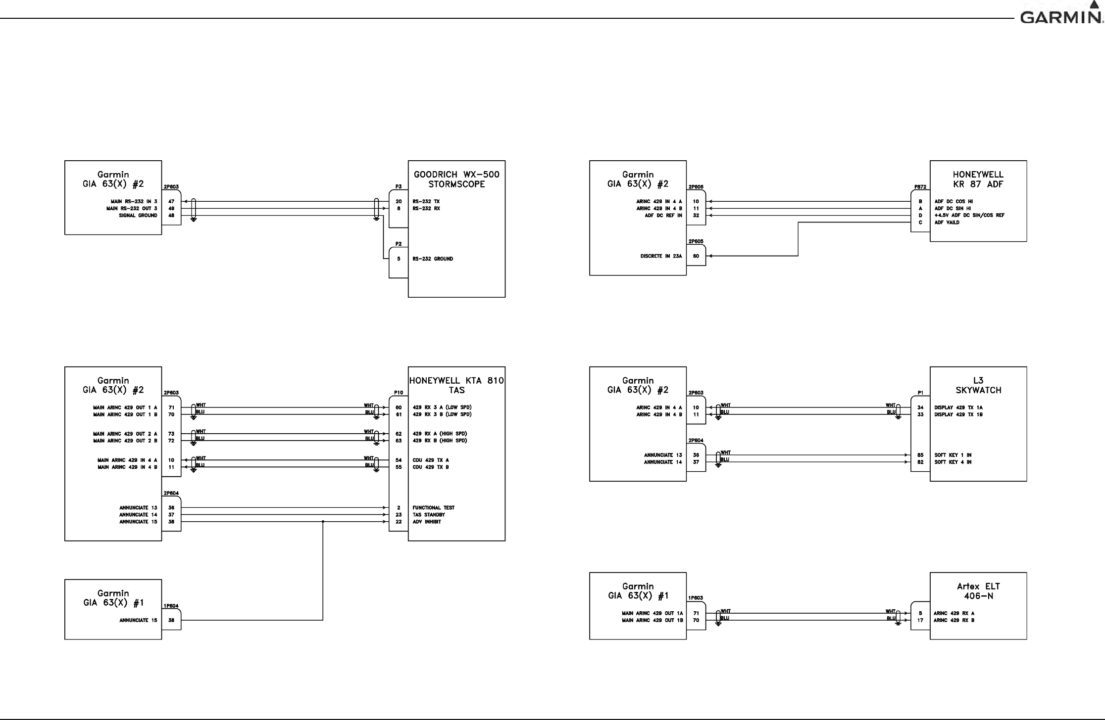
190-00303-05 GIA 63 Installation Manual
Rev. W Page C-7
APPENDIX C INTERCONNECT DRAWINGS
Figure C-7. GIA 63(X) Example Interconnect
DRAFT