Garmin A2552 Marine Radar User Manual
Garmin International Inc Marine Radar
UserManual.wiki
>
Garmin
>
A2552 User Manual
>
User Manual
Contents
1.
User Manual 1
2.
User Manual
3.
User Manual Install Guide
User Manual
Navigation menu
Upload a User Manual
Namespaces
Wiki Guide
HTML
PDF
Info
Views
User Manual
Discussion / Help
Navigation
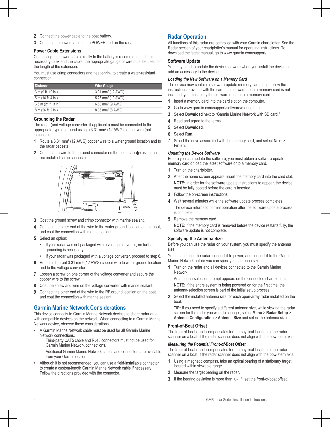
![4Apply the included Petrolatum Primer to one half of the threads of the fourthreaded rods.5Insert the ends of the threaded rods coated in Petrolatum Primer into thepedestal, matching the hole pattern drilled in step 2.6Tighten the threaded rods À using a 5 mm hex wrench Á.To avoid damaging the pedestal, you should stop tightening the threadedrods when they no longer turn easily.7Install the isolators  over the threaded rods, and push them securelyonto the four raised locations on the bottom of the pedestal.Mounting the RadarBefore you can mount the radar, you must first select a mounting location, andprepare the mounting surface and the radar (Preparing the Surface and theRadar for Mounting, page 1).1Take note of which end of the pedestal you plan to mount facing the bowalong the bow-stern axis.If the hatch side is facing the bow, you must adjust the front-of-boat offseton the chartplotter to receive an accurate radar reading (Front-of-BoatOffset, page 4).2Position the included strap over the antenna, as close to the pedestal baseas possible À.3Hoist the radar into position, and carefully lower it onto the mountingsurface, feeding the threaded rods through the holes.4From under the mounting surface, place the shoulder washers Á on thethreaded rods and feed them into the mounting surface so they fit securely.5Place the flat washers Â, lock washers Ã, and hex nuts Ä on thethreaded rods.6Torque the hex nuts to 1.5 kgf-m (130 lbf-in. [11 lbf-ft.]) to securely fastenthe radar to the surface without damaging the radar or the mountinghardware.Installing the AntennaBefore you can install the antenna on the radar, you must securely mount thepedestal (Mounting the Radar, page 2).1Remove the protective cover from the waveguide on the top of thepedestal.2Align the waveguide À on the pedestal with the socket on the bottom ofthe antenna Á, and slide the antenna onto the pedestal.3Secure the antenna to the pedestal using the included hex bolts  andspring washers Ã.2 GMR rdar Series Installation Instructions](https://usermanual.wiki/Garmin/A2552.User-Manual/User-Guide-2771019-Page-2.png)
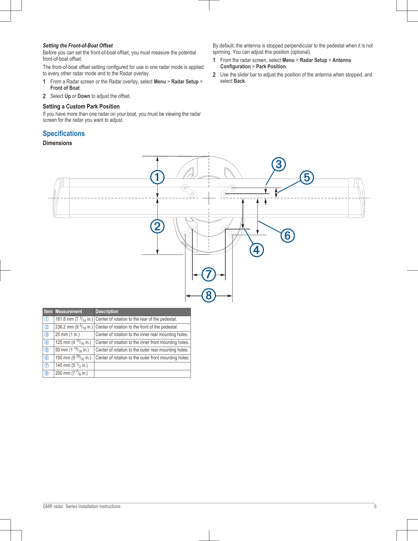
![4Torque the hex bolts to 0.81 kgf-m (70 lfb-in. [6 lbf-ft.]) to fasten theantenna to the pedestal without damaging the antenna or the mountinghardware.Cable ConsiderationsIt may be necessary to drill 31.7 mm (1 ¼ in.) holes for routing the power ornetwork cable. The provided rubber cable grommet can be used to cover acable installation hole.• The grommet does NOT provide a waterproof seal. To make the grommetwaterproof, marine sealant must be applied.•If needed, the grommet can be trimmed to route both the power and thenetwork cable through the same hole.• Additional cable grommets can be purchased from Garmin or a Garmindealer.When installing the power and network cables, you should observe theseconsiderations.• Cutting the Garmin Marine Network cable is not recommended, but a fieldinstall kit can be purchased from Garmin or a Garmin dealer if cutting thenetwork cable is necessary.• To ensure safety, appropriate tie-wraps, fasteners, and sealant should beused to secure the cable along the route and through any bulkheads or thedeck.• Cables should not be run near moving objects and high-heat sources orthrough doorways and bilges.• To avoid interference with other equipment, power and network cablesshould not be run next to or parallel to other cables, such as radio antennalines or power cables. If this is not possible, the cables should be shieldedwith metal conduit or a form of EMI shielding.• The power cable should be installed as close to the battery source aspossible.◦ If it is necessary to extend the power cable, the appropriate gauge ofwire must be used (Power Cable Extensions, page 4).◦ Incorrectly extended runs of cable may cause the radar to malfunctiondue to insufficient power transmission.Connecting to Power Through the Voltage Converter WARNINGWhen connecting the power cable, do not remove the in-line fuse holder. Toprevent the possibility of injury or product damage caused by fire oroverheating, the appropriate fuse must be in place as indicated in the productspecifications. In addition, connecting the power cable without the appropriatefuse in place will void the product warranty.NOTICEDo not reuse any voltage converters from previous Garmin radar models, orthird party voltage converters. Using any converter other than one includedwith the radar may damage the radar or prevent it from turning on.Some radar models require a voltage converter unit to properly power thedevice. If your model is packaged with a voltage converter, it must be installedin order for your radar to function. If your model is not packaged with a voltageconverter, connect the power cable directly to the boat battery (ConnectingDirectly to Power, page 3).When installing the voltage converter for an applicable radar model, observethese considerations.• The voltage converter requires an input voltage of 10 to 32 Vdc.•It is recommended to install the voltage converter as close as possible tothe power source.• Connecting the power cable for the voltage converter directly to the batteryis recommended. If it is necessary to extend the cable, the appropriategauge of wire must be used for the length of the extension (Power CableExtensions, page 4).Item DescriptionÀTo the Garmin Marine NetworkÁ7.5 A fuse holderÂRed (+)ÃBlack (-)ÄTo the boat battery (10 to 32 Vdc)Water ground connection1Route the power cable to the radar and the voltage converter.2Use crimp connectors and heat-shrink tubing to connect the power cable tothe voltage converter.The radar power cable contains a 7.5 A fuse which should not be removedwhen connecting to the voltage converter.3Connect the voltage converter to the boat battery through a 15 A, slow-blow fuse (not included).The 15 A fuse (not included) between the voltage converter and battery isin addition to the 7.5 A fuse included in the radar power cable. Both fusesmust be in place for the radar to function properly.4Connect the power cable to the POWER port on the radar.Connecting Directly to Power WARNINGWhen connecting the power cable, do not remove the in-line fuse holder. Toprevent the possibility of injury or product damage caused by fire oroverheating, the appropriate fuse must be in place as indicated in the productspecifications. In addition, connecting the power cable without the appropriatefuse in place will void the product warranty.Some radar models do not require a voltage converter unit. If your model ispackaged without a voltage converter, it should be connected directly topower.Item DescriptionÀTo the Garmin Marine NetworkÁ15 A fuse holderÂTo the boat battery (10 to 32 Vdc)Water ground connection1Route the power cable to the radar and boat battery.GMR radar Series Installation Instructions 3](https://usermanual.wiki/Garmin/A2552.User-Manual/User-Guide-2771019-Page-3.png)