Garmin GRMNAIS600 Marine Transceiver User Manual
Garmin International Inc Marine Transceiver
UserManual.wiki
>
Garmin
>
GRMNAIS600 User Manual
User Manual
Navigation menu
Upload a User Manual
Namespaces
Wiki Guide
HTML
PDF
Info
Views
User Manual
Discussion / Help
Navigation
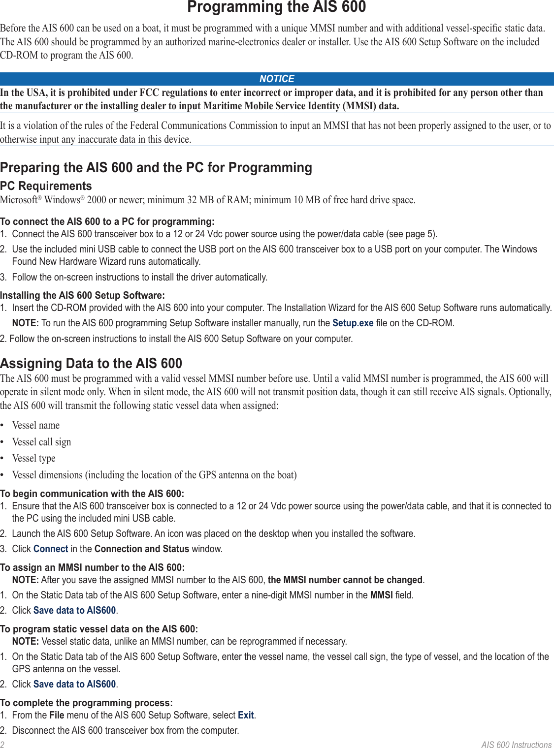
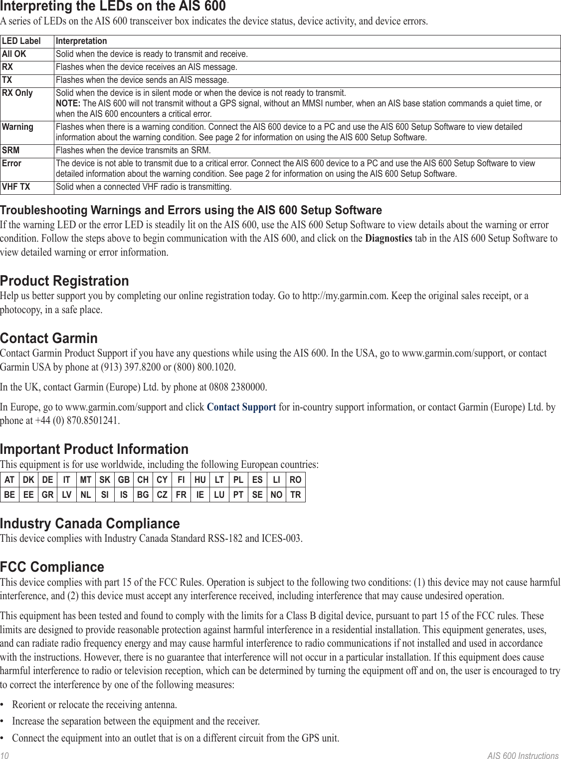
![4 AIS 600 Instructions>>>>See page 8 for silent mode and Safety-Related Message (SRM) wiring assignmentsSilent-mode switch(optional - not included)SRM switch(optional - not included)12 or 24 VdcChartplotter powerVHF radio powerVHF radio**(optional - not included)Garmin NMEA 0183-compatible chartplotter(optional - not included)RF interconnect cable (included)GA 30 GPS antenna* (included)AIS 600 transceiver boxRF cable to VHF antenna(not included)Gray [Tx A (+)]Pink [Tx B (-)]Yellow [power toggle]Wire color [function]White [Rx A (+)]Orange/White [Rx B (-)]Orange [power toggle]Wire color [function]***AIS 600 Wiring Layout: AIS 600 Connected to a Garmin Chartplotter Through NMEA 0183Notes:* The AIS 600 must be connected to the included GA 30 GPS antenna. The AIS 600 does not share GPS information with any other devices on the boat. If you have a chartplotter on your boat, it must receive GPS information from a separate antenna, such as a GPS 17x.** The AIS 600 does not need to be installed alongside a VHF radio, but they can share the same VHF antenna if they are both installed on your boat.*** The listed wire colors are for the NMEA 0183 Port 1 input on a Garmin GPSMAP 4000/5000/6000/7000 series chartplotter. Refer to the installation instructions provided with your Garmin chartplotter if you want to wire the AIS 600 to a different model of Garmin chartplotter or to a different NMEA 0183 port on a GPSMAP 4000/5000/6000/7000 series chartplotter. If you are connecting the AIS 600 to a non-garmin chartplotter, see page 8 for detailed wiring assignments.](https://usermanual.wiki/Garmin/GRMNAIS600/User-Guide-1225316-Page-4.png)
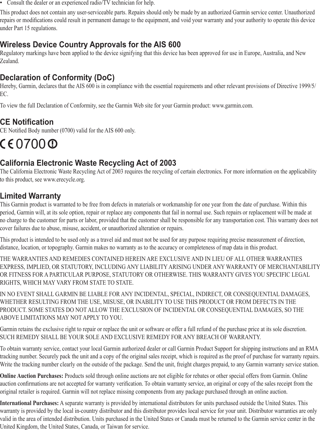
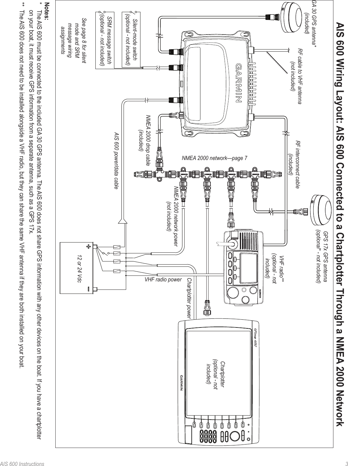
![8 AIS 600 InstructionsConnecting the AIS 600 Series to a NMEA 0183 Device (Optional)You can connect the AIS 600 to a NMEA 0183-compliant chartplotter using the bare wires on the AIS 600 power/data cable. Connect NMEA 0183 bare wires to a Garmin chartplotter as indicated in the wiring layout diagram on page 4. Consult the diagram below to connect the AIS 600 to a non-Garmin chartplotter. Use 22 AWG wire for extended runs of wire, if needed.Connecting the AIS 600 to a Non-Garmin NMEA 0183 Device+->>>>NMEA 0183-compliant chartplotterAIS 600 transceiver boxBattery 12 or 24 VdcGray [Tx A (+)]Pink [Tx B (-)]Red [power (+)]Black [ground (-)]Rx A (+)Rx B (-)Power +Ground -Wire color [function]Wire functionFuse 5AGreen [speed select] Unconnected = 38400 (high speed) Connected to battery negative (-) = 4800 (standard speed)Yellow [power toggle—page 5]Notes:Consult the installation instructions for your NMEA 0183-compliant device to identify the receiving (RX) A(+) and B(-) wires.If your NMEA 0183-compliant device has only one receiving wire (Rx), connect it to the gray wire [Tx A (+)] from the AIS 600, and leave the pink wire [Tx B (-)] wire unconnected.The AIS 600 can transmit NMEA 0183 data using either 38400 baud (default) or 4800 baud. Connect the green wire from the AIS 600 power/data cable to the negative (-) battery terminal if you would like to limit the output speed to 4800 baud. You can install a switch between the green wire and the negative (-) battery terminal in order to toggle the output speed manually.Wiring the AIS 600 to a Physical Switch to Send a Safety-Related Message (SRM) or Enter Silent Mode (Optional)If you connected the AIS 600 to a Garmin chartplotter using NMEA 2000 or NMEA 0183, you can enter silent mode (receive only) or send an SRM from the chartplotter software. See the owner’s manual provided with your chartplotter for more information. In addition, you can also enter silent mode or send an SRM by installing a physical switch.NOTE: If you connected the AIS 600 to a non-Garmin chartplotter or did not connect it to a chartplotter, you must install a physical switch to activate silent mode, send the SRM, or both. There is no guarantee that a non-Garmin chartplotter can toggle the AIS 600 silent mode or send an SRM using software.Wiring the AIS 600 to a Silent-Mode SwitchWhen in silent mode, you will only receive AIS signals; your position will not be transmitted.Use the bare wires from the included SRM cable to install a silent-mode switch. Connect the yellow wire from the SRM cable to one terminal of a single-pole, single-throw switch (not included), and connect the green wire from the SRM cable to the other terminal. After the switch is installed, when you close the switch, the AIS 600 enters silent mode. Wiring the AIS 600 to an SRM SwitchUse the bare wires from the included SRM cable to install an SRM switch. Connect the white wire from the SRM cable to one terminal of a single-pole, single-throw switch (not included), and connect the black wire from the SRM cable to the other terminal. After the switch is installed, closing the switch broadcasts a pan-pan urgency SRM. While the switch is closed, the AIS 600 will send the urgency message at a rate of one message per minute.•••](https://usermanual.wiki/Garmin/GRMNAIS600/User-Guide-1225316-Page-8.png)