Garmin GRMNAIS600 Marine Transceiver User Manual
Garmin International Inc Marine Transceiver
Garmin >
User Manual
Use these instructions to program and install the Garmin
®
AIS 600 marine Automatic Identication System (AIS) Class B transponder device.
Compare the contents of this package with the packing list on the box. If any pieces are missing, contact your Garmin dealer immediately.
WARNING
When navigating, carefully compare information provided by the unit to all available navigation sources, including information from visual
sightings, local waterway rules and restrictions, and maps. For safety, always resolve any discrepancies or questions before continuing
navigation.
Use this unit only as a navigational aid. Do not attempt to use the unit for any purpose requiring precise measurement of direction, distance,
location, or topography.
This product, its packaging, and its components contain chemicals known to the State of California to cause cancer, birth defects, or
reproductive harm. This Notice is provided in accordance with California’s Proposition 65. See www.garmin.com/prop65 for more information.
CAUTION
Wear safety goggles and a dust mask when drilling, cutting, or sanding.
Notice
To prevent possible damage to your equipment, the VHF antenna must be connected to the AIS 600 before transmitting. This ensures that the
power output to the antenna port dissipates properly when transmitting.
Electromagnetic Energy Exposure and Antenna Mounting
The AIS 600 generates and radiates radio frequency (RF) electromagnetic energy (EME). Failure to observe these guidelines may expose
persons to RF radiation absorption exceeding the maximum permissible exposure (MPE).
Garmin declares an MPE radius of 59 in. (1.5 m.) for this system, which was determined using 2 watts output to an omni-directional 9 dBi gain
antenna. The antenna should be installed such that a distance of 59 in. (1.5 m) is maintained between the antenna and all persons.
When sharing the VHF antenna with a VHF radio, refer to the documentation provided with the radio for additional MPE information specic
to the installed VHF radio.
WARNING:
Radio operators with cardiac pacemakers, life-support machines, or electrical medical equipment should not be exposed to excessive radio-
frequency elds.
Operate the device in accordance with the instructions supplied.
Notice
The device complies with internationally recognized standards covering human exposure to electromagnetic elds from radio devices.
Check with the local authorities for any antenna or operational restrictions that may apply.
Safe Compass Distance
Ensure that you install the AIS 600 transceiver box at least 15
3
/
4
in. (40 cm) from any compass. Test your compass to verify that it operates
correctly when the device is operating.
Licensing Requirements
In many countries, the operation of an AIS device is included in the VHF license provisions. Therefore, the vessel on which the AIS 600 is
installed must possess a current VHF license that lists the AIS system, the vessel Call Sign, and the vessel MMSI number. Contact the relevant
authority in your country to ensure that your VHF license covers the AIS 600 device.
AIS 600 Instructions
December 2009 190-01151-00 Rev. B Printed in Germany

2 AIS 600 Instructions
Programming the AIS 600
Before the AIS 600 can be used on a boat, it must be programmed with a unique MMSI number and with additional vessel-specic static data.
The AIS 600 should be programmed by an authorized marine-electronics dealer or installer. Use the AIS 600 Setup Software on the included
CD-ROM to program the AIS 600.
Notice
In the USA, it is prohibited under FCC regulations to enter incorrect or improper data, and it is prohibited for any person other than
the manufacturer or the installing dealer to input Maritime Mobile Service Identity (MMSI) data.
It is a violation of the rules of the Federal Communications Commission to input an MMSI that has not been properly assigned to the user, or to
otherwise input any inaccurate data in this device.
Preparing the AIS 600 and the PC for Programming
PC Requirements
Microsoft
®
Windows
®
2000 or newer; minimum 32 MB of RAM; minimum 10 MB of free hard drive space.
To connect the AIS 600 to a PC for programming:
1. Connect the AIS 600 transceiver box to a 12 or 24 Vdc power source using the power/data cable (see page 5).
2. Use the included mini USB cable to connect the USB port on the AIS 600 transceiver box to a USB port on your computer. The Windows
Found New Hardware Wizard runs automatically.
3. Follow the on-screen instructions to install the driver automatically.
Installing the AIS 600 Setup Software:
1. Insert the CD-ROM provided with the AIS 600 into your computer. The Installation Wizard for the AIS 600 Setup Software runs automatically.
NOTE: To run the AIS 600 programming Setup Software installer manually, run the Setup.exe le on the CD-ROM.
2. Follow the on-screen instructions to install the AIS 600 Setup Software on your computer.
Assigning Data to the AIS 600
The AIS 600 must be programmed with a valid vessel MMSI number before use. Until a valid MMSI number is programmed, the AIS 600 will
operate in silent mode only. When in silent mode, the AIS 600 will not transmit position data, though it can still receive AIS signals. Optionally,
the AIS 600 will transmit the following static vessel data when assigned:
Vessel name
Vessel call sign
Vessel type
Vessel dimensions (including the location of the GPS antenna on the boat)
To begin communication with the AIS 600:
1. Ensure that the AIS 600 transceiver box is connected to a 12 or 24 Vdc power source using the power/data cable, and that it is connected to
the PC using the included mini USB cable.
2. Launch the AIS 600 Setup Software. An icon was placed on the desktop when you installed the software.
3. Click Connect in the Connection and Status window.
To assign an MMSI number to the AIS 600:
NOTE: After you save the assigned MMSI number to the AIS 600, the MMSI number cannot be changed.
1. On the Static Data tab of the AIS 600 Setup Software, enter a nine-digit MMSI number in the MMSI eld.
2. Click Save data to AIS600.
To program static vessel data on the AIS 600:
NOTE: Vessel static data, unlike an MMSI number, can be reprogrammed if necessary.
1. On the Static Data tab of the AIS 600 Setup Software, enter the vessel name, the vessel call sign, the type of vessel, and the location of the
GPS antenna on the vessel.
2. Click Save data to AIS600.
To complete the programming process:
1. From the File menu of the AIS 600 Setup Software, select Exit.
2. Disconnect the AIS 600 transceiver box from the computer.
•
•
•
•
AIS 600 Instructions 3
Notes:
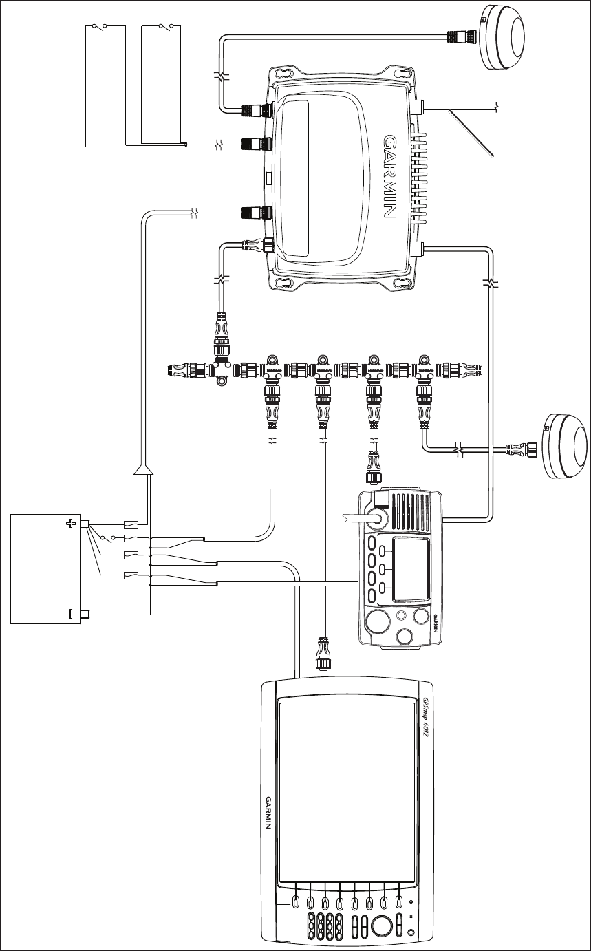
* The AIS 600 must be connected to the included GA 30 GPS antenna. The AIS 600 does not share GPS information with any other devices on the boat. If you have a chartplotter
on your boat, it must receive GPS information from a separate antenna, such as a GPS 17x.
** The AIS 600 does not need to be installed alongside a VHF radio, but they can share the same VHF antenna if they are both installed on your boat.
See page 8 for silent
mode and SRM
message wiring
assignments
Silent-mode switch
(optional - not included)
SRM message switch
(optional - not included)
VHF radio**
(optional - not
included)
GA 30 GPS antenna*
(included)
GPS 17x GPS antenna
(optional* - not included)
Chartplotter
(optional - not
included)
NMEA 2000 network—page 7
NMEA 2000 network power
(not included)
RF cable to VHF antenna
(not included) RF interconnect cable
(included)
AIS 600 power/data cable
NMEA 2000 drop cable
(included)
12 or 24 Vdc
Chartplotter power
VHF radio power
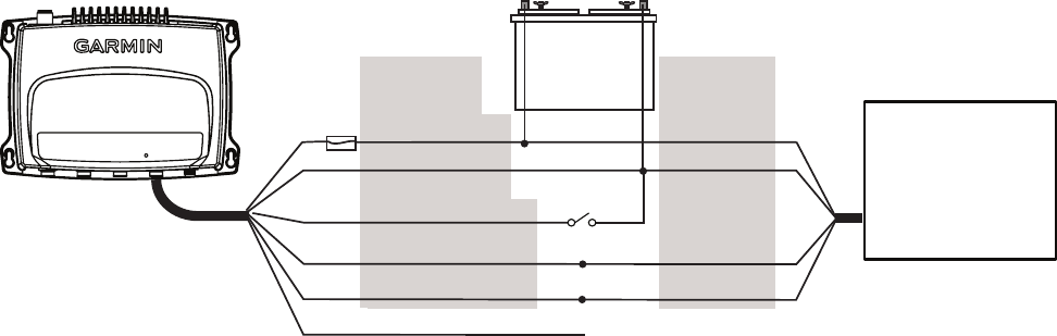
AIS 600 Wiring Layout: AIS 600 Connected to a Chartplotter Through a NMEA 2000 Network
4 AIS 600 Instructions
>
>
>
>
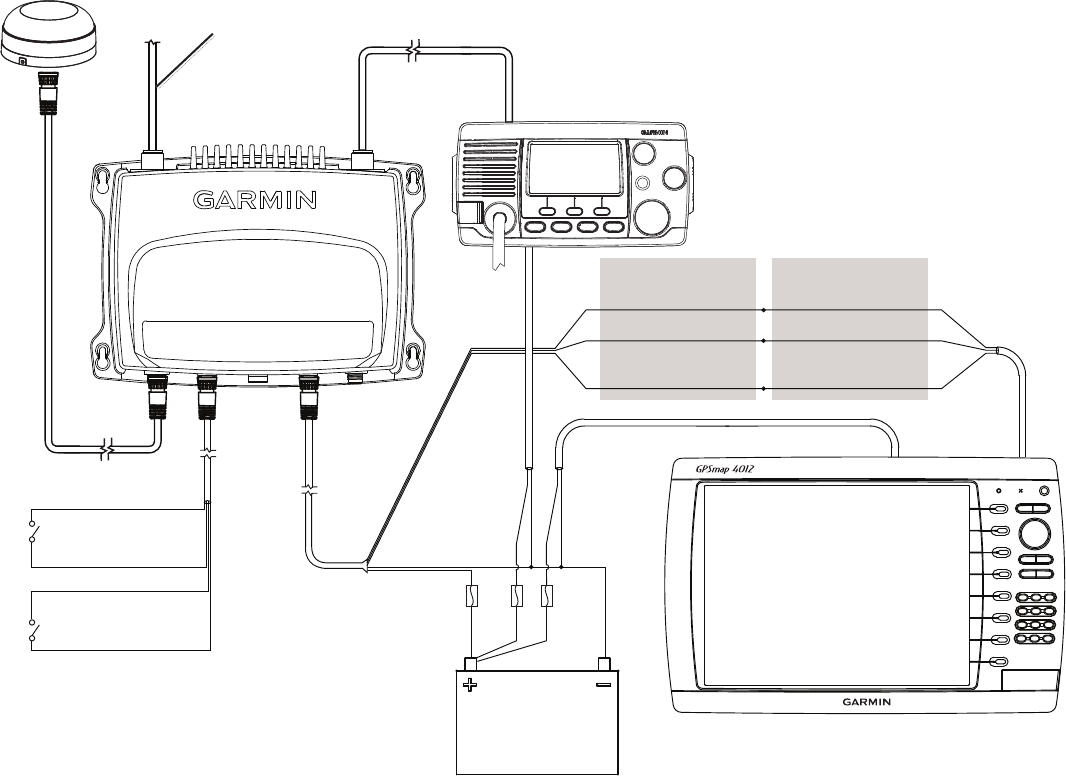
See page 8 for silent mode and
Safety-Related Message (SRM)
wiring assignments
Silent-mode switch
(optional - not included)
SRM switch
(optional - not included)
12 or 24 Vdc
Chartplotter power
VHF radio power
VHF radio**
(optional - not
included)
Garmin NMEA 0183-
compatible chartplotter
(optional - not included)
RF interconnect cable
(included)
GA 30 GPS antenna*
(included)
AIS 600 transceiver box
RF cable to VHF antenna
(not included)
Gray [Tx A (+)]
Pink [Tx B (-)]
Yellow
[power toggle]
Wire color [function]
White [Rx A (+)]
Orange/White [Rx B (-)]
Orange
[power toggle]
Wire color [function]***
AIS 600 Wiring Layout: AIS 600 Connected to a Garmin Chartplotter Through
NMEA 0183
Notes:
* The AIS 600 must be connected to the included GA 30 GPS antenna. The AIS 600 does not share GPS information with any other devices
on the boat. If you have a chartplotter on your boat, it must receive GPS information from a separate antenna, such as a GPS 17x.
** The AIS 600 does not need to be installed alongside a VHF radio, but they can share the same VHF antenna if they are both installed on
your boat.
*** The listed wire colors are for the NMEA 0183 Port 1 input on a Garmin GPSMAP 4000/5000/6000/7000 series chartplotter. Refer to the
installation instructions provided with your Garmin chartplotter if you want to wire the AIS 600 to a different model of Garmin chartplotter or to
a different NMEA 0183 port on a GPSMAP 4000/5000/6000/7000 series chartplotter.
If you are connecting the AIS 600 to a non-garmin chartplotter, see page 8 for detailed wiring assignments.

AIS 600 Instructions 5
Installing the AIS 600
Use the following instructions to install the AIS 600 device. Details for the following steps are included in this document:
1. Select locations for the AIS components.
2. Mount the AIS 600 transceiver box.
3. Wire the AIS 600 to power.
4. Install and connect the GA 30 GPS antenna (page 6).
5. Connect the AIS 600 to a VHF antenna and to an optional VHF radio (page 7).
6. Connect the AIS 600 to a NMEA 2000 network or to a NMEA 0183-compatible chartplotter (optional - page 7).
7. Add a silent-mode switch or a Safety Related Message (SRM) switch (optional - page 8).
Selecting Locations for the AIS 600 Components
Use the wiring layout diagrams starting on page 3 to determine how to best organize the AIS 600 components on your boat. Ensure that the
cables reach all components before permanently mounting any component.
Mounting the AIS 600 Transceiver Box
Install the AIS 600 transceiver box below deck on a bulkhead. Select a location that is dry and protected from washdown. Ensure that the
location is well ventilated and away from objects that generate heat. Ensure that the transceiver box is at least 15
3
/
4
in. (40 cm) from any
compass to avoid interference.
Needed Tools
Drill and drill bits
Number 2 Phillips screwdriver
To mount the transceiver box:
1. Ensure that the chosen location is dry, protected, and well-ventilated.
2. Use the transceiver box as a template, and use a pencil to mark the holes in the four corners. Do not drill through the transceiver box.
3. Drill four 1/8 in. (3 mm) pilot holes.
4. Mount the transceiver box using the included M4.2 × 25 screws. You can also use bolts, washers, and nuts (not included) to mount the
transceiver box if the mounting surface is suitable.
Connecting the Transceiver Box to Power
Use the AIS 600 power/data cable to connect the transceiver box to a 12 or 24 Vdc battery.
Notes:
Use the AIS 600 Power Wiring-Assignment Table to identify the positive and negative wires.
The replacement fuse on the power/data wiring harness is a 5 A, fast-acting fuse.
If it is necessary to extend the power wires, use 16 AWG or larger wire.
If your boat has an electrical system, you can possibly wire the AIS 600
directly to an unused holder on your fuse block. If you wire the AIS 600 to the
fuse block, remove the in-line fuse holder supplied with the power/data cable.
Installing the AIS 600 Power Toggle
The AIS 600 can be powered on and off in one of 3 ways:
If the AIS 600 is connected to a NMEA 2000 network, it will toggle on and off with the NMEA 2000 network.
NOTE: the AIS 600 is not powered by the NMEA 2000 network, though it will turn on when it detects power on the NMEA 2000 network.
You must connect the AIS 600 to power, and not just to the NMEA 2000 network.
If the AIS 600 is wired to a Garmin chartplotter using NMEA 0183, connect the yellow wire from the AIS 600 power/data cable to the
Accessory On wire from the chartplotter. The AIS 600 will then toggle on or off with the Garmin chartplotter.
•
•
•
•
•
•
•
•
Device Wire Color Function
AIS 600 power/data
cable
Red Power—positive (+)
Black Ground—negative (-)
AIS 600 Power Wiring-Assignment Table
Device Wire Color Function
AIS 600 power/data
cable
Red Power—positive (+)
Black Ground—negative (-)
AIS 600 Power Wiring-Assignment Table
6 AIS 600 Instructions
If the AIS 600 is wired to a non-Garmin NMEA 0183 chartplotter, or not wired to a chartplotter at all, then you must install a toggle switch
to turn the device on and off.
Connect the yellow wire from the AIS 600 power/data cable to one terminal of a single-pole, single-throw switch (not included), and
connect the other terminal to the negative (-) battery terminal.
When you close the switch, the AIS 600 powers on. When you open the switch, the AIS 600 powers off.
Installing the GA 30 GPS Antenna
You must install the included GA 30 GPS antenna and connect it to the AIS 600 according to the following instructions. The AIS 600 will not
transmit a signal unless the GA 30 is installed properly and receiving a satellite signal.
The AIS 600 does not accept GPS information from any other GPS device or antenna on the boat. Also, the AIS 600 does not share GPS
information from the GA 30 antenna with any other device on the boat.
You can surface mount the GA 30 antenna or attach the antenna to a standard 1 in. OD pipe-threaded-pole marine mount (14 threads per inch—
not included).
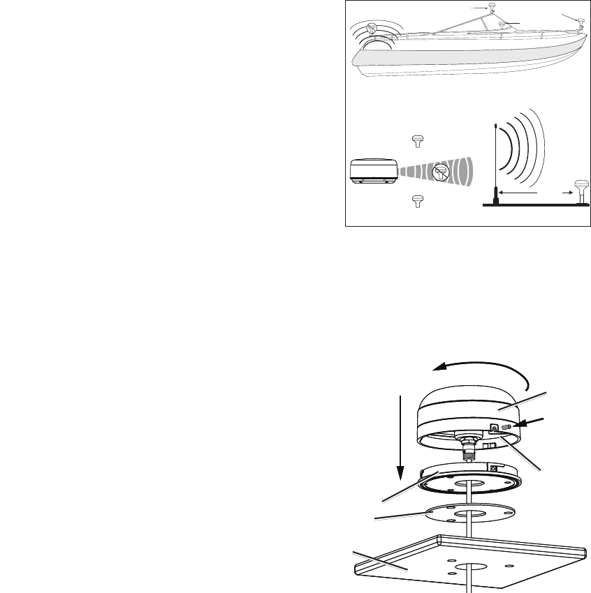
Select a suitable location for the GA 30 antenna on your boat. To ensure the best reception,
mount the GA 30 antenna in a location with a clear view of the sky in all directions.
Avoid mounting the GA 30 antenna in the shade of the superstructure of the boat, a radome
antenna, or a mast.
Mount the GA 30 antenna at least 3 ft. (1 m) away from (preferably above) the path of
any radar beam or a VHF radio antenna.
Temporarily secure the antenna in the preferred mounting location and test it for correct
operation. If you experience interference from other electronics, try a different location. When
you verify correct operation, permanently mount the antenna.
Surface-mounting the GA 30 Antenna
1 Use the surface-mount bracket as a mounting template.
Use a center punch to mark the three screw locations on the surface.
Use a pencil to trace the cable hole in the center of the bracket.
Set the surface-mount bracket aside. Do not drill through the surface-mount bracket.
2. Drill 1/8 in. (3 mm) pilot holes at the three marked locations.
NOTE: If you are mounting the GA 30 on berglass, it is recommended that you use a countersink bit to drill a clearance counterbore
through the top gelcoat layer (but no deeper). This will help to prevent cracking in
the gelcoat layer when the screws are tightened.
3. Use a 1 in. (25 mm) hole saw to cut the cable hole in the center.
4. Place the seal pad on the bottom of the surface-mount bracket. Ensure that the
screw holes align.
5. Use the included M4 screws to attach the surface-mount bracket to the mounting
surface.
6. Route the cable through the 1 in. (25 mm) cable hole and connect it to the GA 30.
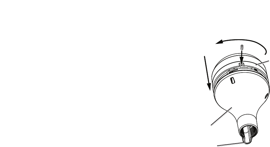
7. Ensure that the large rubber gasket is in place on the bottom of the GA 30 antenna,
place the antenna on the surface-mount bracket
➊
, and twist the antenna
clockwise to lock it in place
➋
.
8. Secure the antenna to the mounting bracket with the included M3 set screw
➌
.
9. Route the cable away from sources of electronic interference, and connect it to the
AIS 600 using the BNC connector.
•
◦
◦
•
•
•
•
•
Radar
SS BARNETT
VHF Radio Antenna
Above - best
Below - OK 3 ft.
(1 m)
EMI (Electromagnetic Interference)
from engine components
Best
Better
Good
EMI
GA 30 Antenna Placement Considerations
Radar
SS BARNETT
VHF Radio Antenna
Above - best
Below - OK 3 ft.
(1 m)
EMI (Electromagnetic Interference)
from engine components
Best
Better
Good
EMI
GA 30 Antenna Placement Considerations
GA 30
antenna
Surface-mount
bracket
Seal pad
Mounting
surface
➊
➋
➌
Rubber
gasket
GA 30
antenna
Surface-mount
bracket
Seal pad
Mounting
surface
➊
➋
➌
Rubber
gasket
AIS 600 Instructions 7
Pole-mounting the GA 30 Antenna
With the pole-mount adapter attached to the GA 30 antenna, you can install the antenna on a standard 1 in. OD pipe-threaded-pole marine
mount (14 threads per inch—not included). You can run the cable through the pole or outside the pole.
To mount the GA 30 with the cable run outside the pole:
1. Route the cable through the pole-mount adapter, and place the cable in the vertical slot along the base of the pole-mount adapter.
2. Thread the pole-mount adapter onto a standard 1 in. OD pipe-threaded-pole marine mount (14 threads per inch—not included). Do not
overtighten the adapter.
3. Connect the cable to the GA 30 antenna.
4. Place the GA 30 antenna on the pole-mount adapter
➊
and twist the antenna clockwise to lock it in place
➋
.
5. Secure the antenna to the adapter with the included M3 set screw
➌
.
6. (Optional) With the GA 30 installed on the pole mount, ll the remaining gap in the vertical cable slot with a marine sealant.
7. Attach the marine pole mount to the boat if it is not already attached.
8. Route the cable away from sources of electronic interference, and connect it to the AIS 600
using the BNC connector.
To mount the GA 30 with the cable run through the pole:
1. Position a standard 1 in. OD pipe-threaded-pole marine mount (14 threads per inch—not
included) in the preferred location, and mark the approximate center of the pole.
2. Drill a 3/4 in. (19 mm) hole for the cable to pass through.
3. Fasten the pole marine mount to the boat.
4. Thread the pole-mount adapter onto the pole. Do not overtighten the adapter.
5. Route the cable through the pole and connect it to the GA 30 antenna.
6. Place the GA 30 antenna on the pole-mount adapter
➊
and twist the antenna clockwise to
lock it in place
➋
.
7. Secure the antenna to the adapter with the included M3 set screw
➌
.
8. (Optional) With the GA 30 installed on the pole mount, ll the vertical cable slot with a marine
sealant.
9. Route the cable away from sources of electronic interference, and connect it to the AIS 600 using the BNC connector.
Connecting a VHF Antenna to the AIS 600
To transmit and receive AIS information, the AIS 600 must be connected to a VHF antenna (not included).
Connect a marine VHF antenna to the AIS 600 using the antenna port on the rear panel of the device. If you have a VHF radio on your boat,
connect the VHF antenna to the AIS 600, and connect the VHF radio to the AIS 600 using the RF interconnect cable according to the wiring
layout diagrams starting on page 3. Mount the antenna according to the installation instructions provided with the antenna.
Connecting the AIS 600 to a NMEA 2000 Network (Optional)
You can connect the AIS 600 to a NMEA 2000-compliant chartplotter using your existing NMEA 2000 network, or you can build a basic
NMEA 2000 network if you do not have one on your boat. For more information on NMEA 2000, and to purchase required cables and
connectors, go to www.garmin.com.
The AIS 600 wiring layout diagram on page 3 contains an example of the AIS 600 connected to Garmin chartplotter through a NMEA 2000
network.
NOTE: If you are unfamiliar with NMEA 2000, see the “NMEA 2000 Network Fundamentals” chapter of the Technical Reference for Garmin
NMEA 2000 Products for more information. Visit www.garmin.com/products/AIS600/, and click on the “Manuals” hyperlink on the AIS 600
page.
GA 30
antenna
Pole-mount
adapter
Vertical cable
slot
➊
➋
➌
GA 30
antenna
Pole-mount
adapter
Vertical cable
slot
➊
➋
➌
8 AIS 600 Instructions
Connecting the AIS 600 Series to a NMEA 0183 Device (Optional)
You can connect the AIS 600 to a NMEA 0183-compliant chartplotter using the bare wires on the AIS 600 power/data cable. Connect
NMEA 0183 bare wires to a Garmin chartplotter as indicated in the wiring layout diagram on page 4. Consult the diagram below to connect the
AIS 600 to a non-Garmin chartplotter. Use 22 AWG wire for extended runs of wire, if needed.
Connecting the AIS 600 to a Non-Garmin NMEA 0183 Device
+-
>
>
>
>
NMEA 0183-
compliant
chartplotter
AIS 600
transceiver box
Battery
12 or 24 Vdc
Gray [Tx A (+)]
Pink [Tx B (-)]
Red [power (+)]
Black [ground (-)]
Rx A (+)
Rx B (-)
Power +
Ground -
Wire color
[function]
Wire function
Fuse 5A
Green [speed select] Unconnected = 38400 (high speed)
Connected to battery negative (-) = 4800 (standard speed)
Yellow
[power toggle—page 5]
Notes:
Consult the installation instructions for your NMEA 0183-compliant device to identify the receiving (RX) A(+) and B(-) wires.
If your NMEA 0183-compliant device has only one receiving wire (Rx), connect it to the gray wire [Tx A (+)] from the AIS 600, and leave
the pink wire [Tx B (-)] wire unconnected.
The AIS 600 can transmit NMEA 0183 data using either 38400 baud (default) or 4800 baud. Connect the green wire from the AIS 600
power/data cable to the negative (-) battery terminal if you would like to limit the output speed to 4800 baud. You can install a switch
between the green wire and the negative (-) battery terminal in order to toggle the output speed manually.
Wiring the AIS 600 to a Physical Switch to Send a Safety-Related Message (SRM) or Enter
Silent Mode (Optional)
If you connected the AIS 600 to a Garmin chartplotter using NMEA 2000 or NMEA 0183, you can enter silent mode (receive only) or send an
SRM from the chartplotter software. See the owner’s manual provided with your chartplotter for more information. In addition, you can also
enter silent mode or send an SRM by installing a physical switch.
NOTE: If you connected the AIS 600 to a non-Garmin chartplotter or did not connect it to a chartplotter, you must install a physical switch to
activate silent mode, send the SRM, or both. There is no guarantee that a non-Garmin chartplotter can toggle the AIS 600 silent mode or send an
SRM using software.
Wiring the AIS 600 to a Silent-Mode Switch
When in silent mode, you will only receive AIS signals; your position will not be transmitted.
Use the bare wires from the included SRM cable to install a silent-mode switch. Connect the yellow wire from the SRM cable to one terminal
of a single-pole, single-throw switch (not included), and connect the green wire from the SRM cable to the other terminal. After the switch is
installed, when you close the switch, the AIS 600 enters silent mode.
Wiring the AIS 600 to an SRM Switch
Use the bare wires from the included SRM cable to install an SRM switch. Connect the white wire from the SRM cable to one terminal of
a single-pole, single-throw switch (not included), and connect the black wire from the SRM cable to the other terminal. After the switch is
installed, closing the switch broadcasts a pan-pan urgency SRM. While the switch is closed, the AIS 600 will send the urgency message at a rate
of one message per minute.
•
•
•
AIS 600 Instructions 9
Using the AIS 600
If you connected the AIS 600 device to a chartplotter using either NMEA 2000 or NMEA 0183, refer to the Owner’s Manual provided with your
chartplotter for information on using the AIS-specic features of the chartplotter.
If you did not connect the AIS 600 device to a chartplotter (to only broadcast position information), ensure that you wired a power toggle
switch using the yellow wire on the AIS 600 power/data cable (see page 5). When you want to turn on the AIS 600 and broadcast your position
information, close the switch. When you want to turn off the AIS 600, open the switch.
Appendix
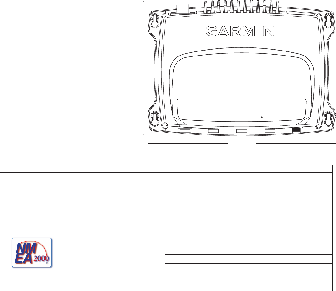
Specications
Dimensions: W × H × D: 9
3
/
4
× 7
3
/
32
× 2
1
/
2
in. (248 × 180 × 64 mm)
Weight: 4.177 lb. (1.895 kg)
Temperature Range: from -4ºF to 149ºF
(from -20ºC to 65ºC)
Compass-safe Distance: 15
3
/
4
in. (40 cm)
Waterproof Rating: IEC 60529 IPX7 (Immersion in
1 meter of standing water for 30 minutes)
Power
Source: 9.6–31.2 Vdc
(12 Vdc or 24 Vdc boat battery)
Usage: 20 W max
Fuse: 5 A fast-acting
NMEA 2000 Power Usage: LEN=2
Antenna
Antenna Connector: S0-239 (50 Ω)
Max Antenna Gain: 9 dBi
Antenna Port Impedance: 50 Ω
NMEA 2000 PGN Information
Receive Transmit
059392 ISO Acknowledgment 059392 ISO Acknowledgment
059904 ISO Request 060928 ISO Address Claim
060928 ISO Address Claim 126208 NMEA Request/Command/Acknowledge Group Function
126208 NMEA - Command/Request/Acknowledge Group Function 126464 PGN List
126992 System Time 126996 Product Information
129038 AIS Class A Position Report
129039 AIS Class B Position Report
129040 AIS Class B Extended Position Report
The Garmin AIS 600 is NMEA 2000 certied. 129794 AIS Class A Static and Voyage Related Data
129798 AIS SAR Aircraft Position Report
129802 AIS Safety Related Broadcast Message
129809 AIS Class B “CS” Static Data Report, Part A
129810 AIS Class B “CS” Static Data Report, Part B
NMEA 0183 Communication Information
When connected to a NMEA 0183 device, the AIS 600 transmits the following sentences: RMC, VDM, and VDO.
9
3
/
4
in.
(248 mm)
7
3
/
32
in.
(180 mm)
9
3
/
4
in.
(248 mm)
7
3
/
32
in.
(180 mm)

10 AIS 600 Instructions
Interpreting the LEDs on the AIS 600
A series of LEDs on the AIS 600 transceiver box indicates the device status, device activity, and device errors.
LED Label Interpretation
All OK Solid when the device is ready to transmit and receive.
RX Flashes when the device receives an AIS message.
TX Flashes when the device sends an AIS message.
RX Only Solid when the device is in silent mode or when the device is not ready to transmit.
NOTE: The AIS 600 will not transmit without a GPS signal, without an MMSI number, when an AIS base station commands a quiet time, or
when the AIS 600 encounters a critical error.
Warning Flashes when there is a warning condition. Connect the AIS 600 device to a PC and use the AIS 600 Setup Software to view detailed
information about the warning condition. See page 2 for information on using the AIS 600 Setup Software.
SRM Flashes when the device transmits an SRM.
Error The device is not able to transmit due to a critical error. Connect the AIS 600 device to a PC and use the AIS 600 Setup Software to view
detailed information about the warning condition. See page 2 for information on using the AIS 600 Setup Software.
VHF TX Solid when a connected VHF radio is transmitting.
Troubleshooting Warnings and Errors using the AIS 600 Setup Software
If the warning LED or the error LED is steadily lit on the AIS 600, use the AIS 600 Setup Software to view details about the warning or error
condition. Follow the steps above to begin communication with the AIS 600, and click on the Diagnostics tab in the AIS 600 Setup Software to
view detailed warning or error information.
Product Registration
Help us better support you by completing our online registration today. Go to http://my.garmin.com. Keep the original sales receipt, or a
photocopy, in a safe place.
Contact Garmin
Contact Garmin Product Support if you have any questions while using the AIS 600. In the USA, go to www.garmin.com/support, or contact
Garmin USA by phone at (913) 397.8200 or (800) 800.1020.
In the UK, contact Garmin (Europe) Ltd. by phone at 0808 2380000.
In Europe, go to www.garmin.com/support and click Contact Support for in-country support information, or contact Garmin (Europe) Ltd. by
phone at +44 (0) 870.8501241.
Important Product Information
This equipment is for use worldwide, including the following European countries:
AT DK DE IT MT SK GB CH CY FI HU LT PL ES LI RO
BE EE GR LV NL SI IS BG CZ FR IE LU PT SE NO TR
Industry Canada Compliance
This device complies with Industry Canada Standard RSS-182 and ICES-003.
FCC Compliance
This device complies with part 15 of the FCC Rules. Operation is subject to the following two conditions: (1) this device may not cause harmful
interference, and (2) this device must accept any interference received, including interference that may cause undesired operation.
This equipment has been tested and found to comply with the limits for a Class B digital device, pursuant to part 15 of the FCC rules. These
limits are designed to provide reasonable protection against harmful interference in a residential installation. This equipment generates, uses,
and can radiate radio frequency energy and may cause harmful interference to radio communications if not installed and used in accordance
with the instructions. However, there is no guarantee that interference will not occur in a particular installation. If this equipment does cause
harmful interference to radio or television reception, which can be determined by turning the equipment off and on, the user is encouraged to try
to correct the interference by one of the following measures:
Reorient or relocate the receiving antenna.
Increase the separation between the equipment and the receiver.
Connect the equipment into an outlet that is on a different circuit from the GPS unit.
•
•
•

Consult the dealer or an experienced radio/TV technician for help.
This product does not contain any user-serviceable parts. Repairs should only be made by an authorized Garmin service center. Unauthorized
repairs or modications could result in permanent damage to the equipment, and void your warranty and your authority to operate this device
under Part 15 regulations.
Wireless Device Country Approvals for the AIS 600
Regulatory markings have been applied to the device signifying that this device has been approved for use in Europe, Australia, and New
Zealand.
Declaration of Conformity (DoC)
Hereby, Garmin, declares that the AIS 600 is in compliance with the essential requirements and other relevant provisions of Directive 1999/5/
EC.
To view the full Declaration of Conformity, see the Garmin Web site for your Garmin product: www.garmin.com.
CE Notication
CE Notied Body number (0700) valid for the AIS 600 only.
0700
California Electronic Waste Recycling Act of 2003
The California Electronic Waste Recycling Act of 2003 requires the recycling of certain electronics. For more information on the applicability
to this product, see www.erecycle.org.
Limited Warranty
This Garmin product is warranted to be free from defects in materials or workmanship for one year from the date of purchase. Within this
period, Garmin will, at its sole option, repair or replace any components that fail in normal use. Such repairs or replacement will be made at
no charge to the customer for parts or labor, provided that the customer shall be responsible for any transportation cost. This warranty does not
cover failures due to abuse, misuse, accident, or unauthorized alteration or repairs.
This product is intended to be used only as a travel aid and must not be used for any purpose requiring precise measurement of direction,
distance, location, or topography. Garmin makes no warranty as to the accuracy or completeness of map data in this product.
THE WARRANTIES AND REMEDIES CONTAINED HEREIN ARE EXCLUSIVE AND IN LIEU OF ALL OTHER WARRANTIES
EXPRESS, IMPLIED, OR STATUTORY, INCLUDING ANY LIABILITY ARISING UNDER ANY WARRANTY OF MERCHANTABILITY
OR FITNESS FOR A PARTICULAR PURPOSE, STATUTORY OR OTHERWISE. THIS WARRANTY GIVES YOU SPECIFIC LEGAL
RIGHTS, WHICH MAY VARY FROM STATE TO STATE.
IN NO EVENT SHALL GARMIN BE LIABLE FOR ANY INCIDENTAL, SPECIAL, INDIRECT, OR CONSEQUENTIAL DAMAGES,
WHETHER RESULTING FROM THE USE, MISUSE, OR INABILITY TO USE THIS PRODUCT OR FROM DEFECTS IN THE
PRODUCT. SOME STATES DO NOT ALLOW THE EXCLUSION OF INCIDENTAL OR CONSEQUENTIAL DAMAGES, SO THE
ABOVE LIMITATIONS MAY NOT APPLY TO YOU.
Garmin retains the exclusive right to repair or replace the unit or software or offer a full refund of the purchase price at its sole discretion.
SUCH REMEDY SHALL BE YOUR SOLE AND EXCLUSIVE REMEDY FOR ANY BREACH OF WARRANTY.
To obtain warranty service, contact your local Garmin authorized dealer or call Garmin Product Support for shipping instructions and an RMA
tracking number. Securely pack the unit and a copy of the original sales receipt, which is required as the proof of purchase for warranty repairs.
Write the tracking number clearly on the outside of the package. Send the unit, freight charges prepaid, to any Garmin warranty service station.
Online Auction Purchases: Products sold through online auctions are not eligible for rebates or other special offers from Garmin. Online
auction conrmations are not accepted for warranty verication. To obtain warranty service, an original or copy of the sales receipt from the
original retailer is required. Garmin will not replace missing components from any package purchased through an online auction.
International Purchases: A separate warranty is provided by international distributors for units purchased outside the United States. This
warranty is provided by the local in-country distributor and this distributor provides local service for your unit. Distributor warranties are only
valid in the area of intended distribution. Units purchased in the United States or Canada must be returned to the Garmin service center in the
United Kingdom, the United States, Canada, or Taiwan for service.
•

For the latest free software updates (excluding map data) throughout the life of your
Garmin products, visit the Garmin Web site at www.garmin.com.
© 2009 Garmin Ltd. or its subsidiaries
Garmin International, Inc.
1200 East 151st Street, Olathe, Kansas 66062, USA
Garmin (Europe) Ltd.
Liberty House, Hounsdown Business Park, Southampton, Hampshire, SO40 9LR UK
Garmin Corporation
No. 68, Jangshu 2nd Road, Sijhih, Taipei County, Taiwan
www.garmin.com
December 2009 Part Number 190-01151-00 Rev. B Printed in Germany
© 2009 Garmin Ltd. or its subsidiaries
Garmin
®
, the Garmin logo, and GPSMAP
®
are trademarks of Garmin Ltd. or its subsidiaries, registered in the USA and other countries. These trademarks may not be used
without the express permission of Garmin.
Windows
®
is a registered trademark of Microsoft Corporation in the United States and other countries.