Garmin Gtr 200 Installation Manual 190 01553 00
2015-05-27
: Garmin Garmin-Gtr-200-Installation-Manual-720503 garmin-gtr-200-installation-manual-720503 garmin pdf
Open the PDF directly: View PDF ![]() .
.
Page Count: 84
- 1 General Description
- 2 Installation Overview
- 3 Installation Procedures
- 4 Connector Pinout Information
- Appendix A Shield Block Connector Installation Instructions
- A.1 Shield Block Installation Parts
- A.2 Shield Termination Technique – Method A.1 (Standard)
- A.3 Shield Termination Technique - Method A.2 (Daisy Chain)
- A.4 Shield Termination – Method B.1 (Quick Term)
- A.5 Shield Termination-Method B.2 (Daisy Chain-Quick Term)
- A.6 Daisy Chain between Methods A and B
- A.7 Splicing Signal Wires
- Appendix B Serial Interface Specifications
- Appendix C Outline and Installation Drawings
- APPENDIX D Interconnect Examples
190-01553-00 February, 2015 Revision G
GTR 200
COM Transceiver
Installation Manual
190-01553-00 GTR 200 Installation Manual
Rev. G Page A
© 2015
Garmin Ltd. or its subsidiaries
All Rights Reserved
Except as expressly provided herein, no part of this manual may be reproduced, copied,
transmitted, disseminated, downloaded or stored in any storage medium, for any purpose without
the express prior written consent of Garmin. Garmin hereby grants permission to download a
single copy of this manual and of any revision to this manual onto a hard drive or other electronic
storage medium to be viewed and to print one copy of this manual or of any revision hereto,
provided that such electronic or printed copy of this manual or revision must contain the complete
text of this copyright notice and provided further that any unauthorized commercial distribution of
this manual or any revision hereto is strictly prohibited.
Garmin International, Inc.
1200 E. 151st Street
Olathe, KS 66062 USA
Telephone: 913.397.8200
Aviation Panel-Mount Technical Support Line (Toll Free) 1.888.606.5482
www.garmin.com
Garmin (Europe) Ltd.
Liberty House, Hounsdown Business Park
Southampton, Hampshire SO40 9LR U.K.
+44/ (0) 23 8052 4000
Garmin AT, Inc.
2345 Turner Rd., SE
Salem, OR 97302 USA
Telephone: 503.581.8101
RECORD OF REVISIONS
CURRENT REVISION DESCRIPTION
Revision Revision Date Description
A07/19/13 Initial Release
B09/11/13 Corrected panel cutout drawing Fig C-4
C01/08/14 Updated to include new SW features
D04/15/14 Updated to include CAN bus capability
E10/14/14 Updated squelch description and corrected ID pin description
F12/15/14 Made corrections to interconnect drawings
G02/13/15 Updated maximum CAN node length
Revision Page
Number(s)
Section
Number Description of Change
G2-5 2.7.2 Updated maximum CAN node length
D-3 Appdx D Updated max CAN node length in Figure D-2 and Figure D-6
190-01553-00 GTR 200 Installation Manual
Rev. G Page i
INFORMATION SUBJECT TO EXPORT CONTROL LAWS
This document may contain information which is subject to the Export Administration Regulations
("EAR") issued by the United States Department of Commerce (15 CFR, Chapter VII, Subchapter C) and
which may not be exported, released, or disclosed to foreign nationals inside or outside of the United States
without first obtaining an export license. The preceding statement is required to be included on any and all
reproductions in whole or in part of this manual.
DEFINITIONS OF WARNINGS, CAUTIONS, AND NOTES
WARNING
This product, its packaging, and its components contain chemicals known to the State of
California to cause cancer, birth defects, or reproductive harm. This Notice is being
provided in accordance with California's Proposition 65. If you have any questions or
would like additional information, please refer to our web site at www.garmin.com/prop65.
CAUTION
The front bezel, keypad, and display can be cleaned with a microfiber cloth or with
a soft cotton cloth dampened with clean water. DO NOT use any chemical
cleaning agents. Care should be taken to avoid scratching the surface of the
display.
WARNING
Warnings are used to bring to the installer’s immediate attention that not only
damage to the equipment but personal injury may occur if the instruction is
disregarded.
CAUTION
Cautions are used to alert the individual that damage to equipment may
result if the procedural step is not followed to the letter.
NOTE
Notes are used to expand and explain the preceding step and provide further
understanding of the reason for the particular operation.

190-01553-00 GTR 200 Installation Manual
Rev. G Page ii
Aviation Limited Warranty
All Garmin avionics products are warranted to be free from defects in materials or workmanship for: two
years from the date of purchase for new Remote-Mount and Panel-Mount products; one year from the date
of purchase for new portable products and any purchased newly-overhauled products; six months for
newly-overhauled products exchanged through a Garmin Authorized Service Center; and 90 days for
factory repaired or newly-overhauled products exchanged at Garmin in lieu of repair. Within the
applicable period, Garmin will, at its sole option, repair or replace any components that fail in normal use.
Such repairs or replacement will be made at no charge to the customer for parts or labor, provided that the
customer shall be responsible for any transportation cost. This warranty does not apply to: (i) cosmetic
damage, such as scratches, nicks and dents; (ii) consumable parts, such as batteries, unless product damage
has occurred due to a defect in materials or workmanship; (iii) damage caused by accident, abuse, misuse,
water, flood, fire, or other acts of nature or external causes; (iv) damage caused by service performed by
anyone who is not an authorized service provider of Garmin; or (v) damage to a product that has been
modified or altered without the written permission of Garmin. In addition, Garmin reserves the right to
refuse warranty claims against products or services that are obtained and/or used in contravention of the
laws of any country.
THE WARRANTIES AND REMEDIES CONTAINED HEREIN ARE EXCLUSIVE AND IN LIEU OF
ALL OTHER WARRANTIES, WHETHER EXPRESS, IMPLIED OR STATUTORY, INCLUDING ANY
LIABILITY ARISING UNDER ANY WARRANTY OF MERCHANTABILITY OR FITNESS FOR A
PARTICULAR PURPOSE, STATUTORY OR OTHERWISE. THIS WARRANTY GIVES YOU
SPECIFIC LEGAL RIGHTS, WHICH MAY VARY FROM STATE TO STATE.
IN NO EVENT SHALL GARMIN BE LIABLE FOR ANY INCIDENTAL, SPECIAL, INDIRECT OR
CONSEQUENTIAL DAMAGES, WHETHER RESULTING FROM THE USE, MISUSE OR
INABILITY TO USE THE PRODUCT OR FROM DEFECTS IN THE PRODUCT. SOME STATES DO
NOT ALLOW THE EXCLUSION OF INCIDENTAL OR CONSEQUENTIAL DAMAGES, SO THE
ABOVE LIMITATIONS MAY NOT APPLY TO YOU.
Garmin retains the exclusive right to repair or replace (with a new or newly-overhauled replacement
product) the product or software or offer a full refund of the purchase price at its sole discretion. SUCH
REMEDY SHALL BE YOUR SOLE AND EXCLUSIVE REMEDY FOR ANY BREACH OF
WARRANTY.
Online Auction Purchases: Products purchased through online auctions are not eligible for warranty
coverage. Online auction confirmations are not accepted for warranty verification. To obtain warranty
service, an original or copy of the sales receipt from the original retailer is required. Garmin will not
replace missing components from any package purchased through an online auction.
International Purchases: A separate warranty may be provided by international distributors for devices
purchased outside the United States depending on the country. If applicable, this warranty is provided by
the local in-country distributor and this distributor provides local service for your device. Distributor
warranties are only valid in the area of intended distribution. Devices purchased in the United States or
Canada must be returned to the Garmin service center in the United Kingdom, the United States, Canada,
or Taiwan for service.
Garmin International, Inc. Garmin (Europe) Ltd.
1200 East 151st Street Liberty House, Hounsdown Business Park
Olathe, Kansas 66062, U.S.A. Southampton, Hampshire SO40 9LR U.K.
Phone: 913/397.8200 Phone: +44 (0) 23 8052 4000
Fax: 913/397.0836 Fax: +44 (0) 23 8052 4004
Aviation Support: +44 (0) 87 0850 1243

190-01553-00 GTR 200 Installation Manual
Rev. G Page iii
TABLE OF CONTENTS
PARAGRAPH PAGE
Section 1 General Description ...........................................................................1-1
1.1 Introduction...................................................................................................................... 1-1
1.2 Equipment Description .................................................................................................... 1-1
1.3 Technical Specifications .................................................................................................. 1-2
1.4 Certification ..................................................................................................................... 1-5
1.5 Reference Documents ...................................................................................................... 1-5
Section 2 Installation Overview.........................................................................2-1
2.1 Introduction...................................................................................................................... 2-1
2.2 Unit Configurations .........................................................................................................2-1
2.3 Available Accessories...................................................................................................... 2-1
2.4 Installation Considerations .............................................................................................. 2-2
2.5 Antenna Considerations................................................................................................... 2-2
2.6 Mounting Considerations................................................................................................. 2-4
2.7 Cabling and Wiring..........................................................................................................2-4
2.8 Air Circulation and Cooling ............................................................................................ 2-6
2.9 Compass Safe Distance.................................................................................................... 2-6
Section 3 Installation Procedures ......................................................................3-1
3.1 Unpacking the unit........................................................................................................... 3-1
3.2 Wiring Harness Installation ............................................................................................. 3-1
3.3 Backshell Assembly......................................................................................................... 3-2
3.4 Mounting Requirements .................................................................................................. 3-2
3.5 Antenna Installation and Connections ............................................................................. 3-3
3.6 Post Installation Configuration and Checkout Procedures .............................................. 3-4
3.7 Unit Software................................................................................................................. 3-20
3.8 Continued Airworthiness ............................................................................................... 3-22
Section 4 Connector Pinout Information..........................................................4-1
4.1 Pin Function List.............................................................................................................. 4-1
4.2 Power ............................................................................................................................... 4-2
4.3 Lighting Bus .................................................................................................................... 4-2
4.4 CAN Bus.......................................................................................................................... 4-3
4.5 Unit ID ............................................................................................................................. 4-3
4.6 Serial Data – RS-232 ....................................................................................................... 4-4
4.7 MIC Audio....................................................................................................................... 4-4
4.8 Aux Mono Audio ............................................................................................................. 4-5
4.9 Headset Audio.................................................................................................................. 4-5
4.10 Music Inputs .................................................................................................................. 4-5
4.11 Receiver Audio .............................................................................................................. 4-6

190-01553-00 GTR 200 Installation Manual
Rev. G Page iv
PARAGRAPH PAGE
4.12 Pilot/Copilot PTT Inputs................................................................................................ 4-6
4.13 TX Interlock................................................................................................................... 4-6
4.14 Discrete Inputs ............................................................................................................... 4-7
Appendix A Shield Block Connector Installation Instructions .....................A-1
A.1 Shield Block Installation Parts....................................................................................... A-1
A.2 Shield Termination Technique – Method A.1 (Standard) ............................................. A-3
A.3 Shield Termination Technique - Method A.2 (Daisy Chain) ........................................ A-7
A.4 Shield Termination – Method B.1 (Quick Term) .......................................................... A-7
A.5 Shield Termination-Method B.2 (Daisy Chain-Quick Term)........................................ A-9
A.6 Daisy Chain between Methods A and B ...................................................................... A-10
A.7 Splicing Signal Wires .................................................................................................. A-10
Appendix B Serial Interface Specifications.....................................................B-1
B.1 Electrical Interface ..........................................................................................................B-1
B.2 Message Formats.............................................................................................................B-1
Appendix C Outline and Installation Drawings .............................................C-1
Appendix D Interconnect Examples ................................................................D-1

190-01553-00 GTR 200 Installation Manual
Rev. G Page v
LIST OF FIGURES
FIGURE PAGE
Section 1 General Description ...........................................................................1-1
Section 2 Installation Overview.........................................................................2-1
Figure 2-1 CAN Bus Configuration...................................................................................... 2-5
Section 3 Installation Procedures ......................................................................3-1
Figure 3-1 GTR 200 Front Panel .......................................................................................... 3-4
Figure 3-2 Configuration Mode Home Page ........................................................................ 3-5
Figure 3-3 COM Setup Page................................................................................................. 3-7
Figure 3-4 ICS Sidetone Selection........................................................................................ 3-7
Figure 3-5 MON Swap Selection.......................................................................................... 3-8
Figure 3-6 Audio Setup Page (AUX and Music Disabled) .................................................. 3-9
Figure 3-7 Audio Setup Page (AUX and Music Enabled).................................................... 3-9
Figure 3-8 Softkey Setup Page ........................................................................................... 3-10
Figure 3-9 Discrete Setup Page .......................................................................................... 3-11
Figure 3-10 Lighting Setup Page ........................................................................................ 3-12
Figure 3-11 Lighting Graph................................................................................................ 3-13
Figure 3-12 RS-232 Status Page......................................................................................... 3-13
Figure 3-13 Headset Tests Page.......................................................................................... 3-14
Figure 3-14 COM Tests Page ............................................................................................. 3-15
Figure 3-15 Audio Tests Page ............................................................................................ 3-16
Figure 3-16 About Page...................................................................................................... 3-20
Figure 3-17 Software Update Page..................................................................................... 3-20
Figure 3-18 Micro SD Insertion.......................................................................................... 3-21
Figure 3-19 Software Update Page - Scanning Card.......................................................... 3-21
Figure 3-20 Software Update Page - No Update Found..................................................... 3-22
Figure 3-21 Software Update Page - Update Software?..................................................... 3-22
Figure 3-22 Software Update Page - Preparing Update...................................................... 3-22
Figure 3-23 Software Update Page - Unit Will Reboot...................................................... 3-22
Section 4 Connector Pinout Information..........................................................4-1
Figure 4-1 J2001 Looking at rear of unit.............................................................................. 4-1
Figure 4-2 CAN Bus Termination for GTR 200................................................................... 4-3
Appendix A Shield Block Connector Installation Instructions.....................A-1
Figure A-1 Shield Block Install onto a Backshell .............................................................. A-2
Figure A-2 Method A.1 for Shield Termination................................................................. A-3
Figure A-3 Insulation/Contact Clearance ........................................................................... A-5
Figure A-4 Method A.2 (Daisy Chain) for Shield Termination ......................................... A-7

190-01553-00 GTR 200 Installation Manual
Rev. G Page vi
FIGURE PAGE
Figure A-5 Method B.1 (Quick Term) for Shield Termination.......................................... A-8
Figure A-6 Method B.2 (Daisy Chain-Quick Term) for Shield Termination..................... A-9
Figure A-7 Daisy Chain between Methods A and B ........................................................ A-10
Figure A-8 D-Sub Spliced Signal Wire illustration.......................................................... A-11
Appendix B Serial Interface Specifications ....................................................B-1
Appendix C Outline and Installation Drawings .............................................C-1
Figure C-1 GTR 200 Outline Drawing .................................................................................C-1
Figure C-2 GTR 200 Assembly Drawing .............................................................................C-2
Figure C-3 GTR 200 Installation Drawing ...........................................................................C-3
Figure C-4 GTR 200 Panel Cutout Drawing ........................................................................C-4
Appendix D Interconnect Examples ................................................................D-1
Figure D-1 GTR 200 Interconnect Example Notes ............................................................. D-1
Figure D-2 GTR 200- Power & Ground/Intercom/GDU 37X/46X CAN Bus
Interconnect Example ........................................................................................................... D-2
Figure D-3 GTR 200- Power & Ground/Intercom/GDU 37X RS-232 Interconnect
Example ................................................................................................................................ D-3
Figure D-4 GTR 200- Power & Ground/GMA 240/GNS 430/aera 79X Interconnect
Example ................................................................................................................................ D-4
Figure D-5 GTR 200- Mono Audio/Remote Mount Jack Interconnect Example ............... D-5
Figure D-6 GTR 200/CAN Bus Interconnect Drawing ....................................................... D-6
Figure D-7 Dual GTR 200/GMA 240 Interconnect Drawing.............................................. D-7
Figure D-8 GTR 200- J2001 Connector Layout.................................................................. D-8

190-01553-00 GTR 200 Installation Manual
Rev. G Page vii
LIST OF TABLES
TABLE PAGE
Section 1 General Description ...........................................................................1-1
Table 1-1 Available Units..................................................................................................... 1-1
Table 1-2 Physical Characteristics........................................................................................ 1-2
Table 1-3 General Specifications.......................................................................................... 1-2
Table 1-4 Display Specifications.......................................................................................... 1-3
Table 1-5 COM Transmitter Specifications.......................................................................... 1-3
Table 1-6 COM Receiver Specifications .............................................................................. 1-4
Table 1-7 FCC Grant of Equipment Authorization .............................................................. 1-5
Table 1-8 Reference Documents........................................................................................... 1-5
Section 2 Installation Overview.........................................................................2-1
Table 2-1 Catalog Part Numbers .......................................................................................... 2-1
Table 2-2 Standard Kit Accessories...................................................................................... 2-1
Table 2-3 Contents of Connector Kit (011-03240-00), see Figure C-2................................ 2-1
Table 2-4 Optional Accessories............................................................................................ 2-2
Section 3 Installation Procedures ......................................................................3-1
Table 3-1 Recommended Crimp Tools (or Equivalent) ....................................................... 3-1
Table 3-2 Socket Contact Part Numbers............................................................................... 3-1
Table 3-3 Configuration Default Settings............................................................................. 3-6
Table 3-4 COM Setup Page Selections................................................................................. 3-7
Table 3-5 Audio Setup Page Selections................................................................................ 3-9
Table 3-6 Softkey Setup Page Selections ........................................................................... 3-10
Table 3-7 Discrete Setup Page Selections .......................................................................... 3-11
Table 3-8 Lighting Setup Page Selections.......................................................................... 3-12
Table 3-9 Audio Tests Source Selections ........................................................................... 3-16
Table 3-10 Discrete Inputs.................................................................................................. 3-17
Table 3-11 TX Interlock Connections ................................................................................ 3-18
Section 4 Connector Pinout Information..........................................................4-1
Table 4-1 J2001 Connector................................................................................................... 4-1
Appendix A Shield Block Connector Installation Instructions ....................A-1
Table A-1 Parts not supplied for a Shield Block Installation (Figure A-1)......................... A-1
Table A-2 Shielded Cable Preparations for Garmin Connectors......................................... A-3
Table A-3 Shielded Cable Preparations – (Quick Term)..................................................... A-9
Appendix B Serial Interface Specifications ....................................................B-1
Appendix C Outline and Installation Drawings ............................................C-1
Appendix D Interconnect Examples ...............................................................D-1
190-01553-00 GTR 200 Installation Manual
Rev. G Page 1-1
1 GENERAL DESCRIPTION
1.1 Introduction
This manual is intended to provide mechanical and electrical information for use in the planning and
design of an installation of the GTR 200 into an aircraft. This manual is not a substitute for an approved
airframe-specific maintenance manual, installation design drawing, or complete installation data package.
Attempting to install equipment by reference to this manual alone and without first planning or designing
an installation specific to your aircraft may compromise your safety and is not recommended.
1.2 Equipment Description
CAUTION
The GTR 200 has a display that is coated with a special anti-reflective coating that is very
sensitive to waxes and abrasive cleaners. CLEANERS CONTAINING AMMONIA WILL
HARM THE ANTI-REFLECTIVE COATING. It is very important to clean the display
using a clean, lint-free cloth and an eyeglass lens cleaner that is specified as safe for anti-
reflective coatings.
CAUTION
The use of ground-based cellular telephones while aircraft are airborne is prohibited by
FCC rules. Due to potential interference with onboard systems, the use of ground-based
cell phones while the aircraft is on the ground is subject to FAA regulation 14 CFR §91.21.
FCC regulation 47 CFR §22.925 prohibits airborne operation of ground-based cellular
telephones installed in or carried aboard aircraft. Ground-based cellular telephones must
not be operated while aircraft are off the ground. When any aircraft leaves the ground, all
ground-based cellular telephones on board that aircraft must be turned off. Ground-based
cell phones that are on, even in a monitoring state, can disrupt GPS/SBAS performance.
NOTE
All screen shots used in this document are current at the time of publication. Screen shots
are intended to provide visual reference only. All information depicted in screen shots,
including software file names, versions, and part numbers, is subject to change and may
not be up to date.
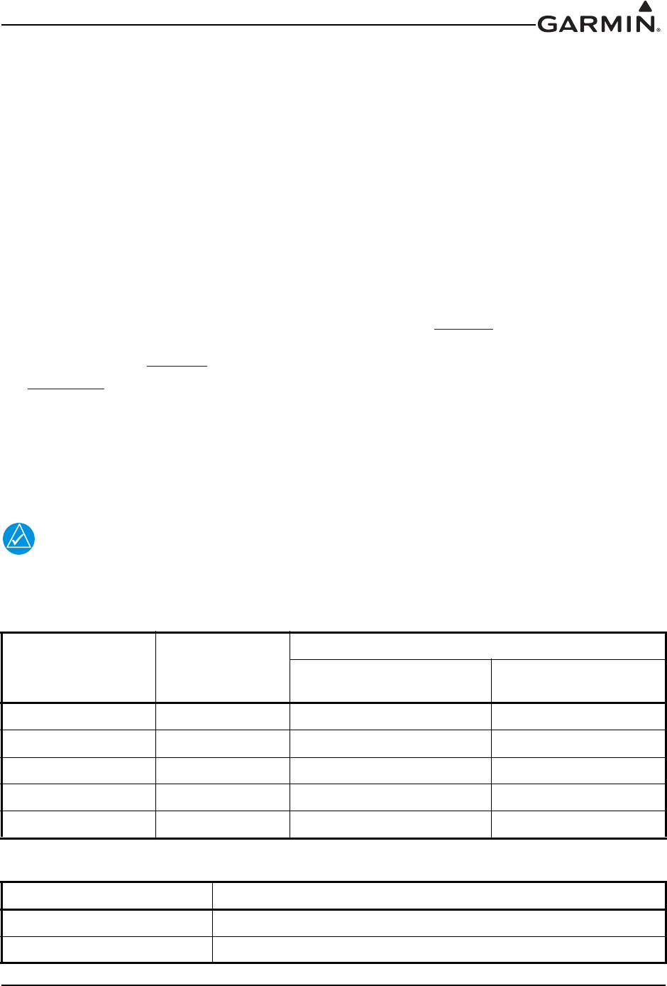
Table 1-1 Available Units
Model Part Number TX Power (Watt) 8.33 KHz Spacing 25 KHz Spacing
GTR 200 011-02980-00 10 N/A Yes

190-01553-00 GTR 200 Installation Manual
Rev. G Page 1-2
1.3 Technical Specifications
1.3.1 Physical Characteristics
1.3.2 General Specifications
Table 1-2 Physical Characteristics
Characteristics Specifications
Bezel Height 1.35 in (34.29 mm)
Bezel Width 6.25 in (158.8 mm)
Rack Height (Dimple-to-Dimple) 1.375 in (34.93 mm)
Rack Width 6.30 in (160.02 mm)
Depth Behind Panel with Connectors (Measured
from face of aircraft panel to rear of connector
backshells)
9.39 in (238.51 mm)
GTR 200 Weight (Unit Only) 1.34 lbs (0.61 kg)
GTR 200 (Installed with rack and connectors) 1.91 lbs (0.87 kg)
Table 1-3 General Specifications
Characteristics Specifications
Operating Temperature Range -20C to +55C
Humidity 95% non-condensing
Altitude Range -1,500 ft to 55,000 ft
Input Voltage Range 14/28 VDC
Current Draw* at 14 VDC
0.6 A, Typical when receiving
3.0 A, Typical when transmitting
7.50 A Maximum, 90% modulated into 3:1
VSWR and 11V power input voltage
Current Draw* at 28 VDC
0.30 A, Typical when receiving
1.40 A, Typical when transmitting
3.75 A Maximum, 90% modulated into 3:1
VSWR and 22V power input voltage
*The specified current draw is with the display backlight set to 100%

190-01553-00 GTR 200 Installation Manual
Rev. G Page 1-3
1.3.3 Display
The display on the GTR is a sunlight readable LCD display.
1.3.4 COM Specifications
The GTR 200 transmitter meets the requirements of RTCA DO-186B section 2.3 for a class 4 transmitter.
Table 1-4 Display Specifications
Characteristics Specifications
Display Size Width: 3.46” (88.0mm)
Height: 0.843” (21.4mm)
Active Area Width: 2.95” (74.98mm)
Height: 0.486” (12.36mm)
Resolution 200 x 33 pixels
Viewing Angle
Left: 45
Right: 45°
Up: 10
Down: 30
Table 1-5 COM Transmitter Specifications
Characteristics Specifications
Microphone Input
Two inputs, standard carbon or dynamic mic with integrated
preamp. The GTR 200 provides a 150 Ω AC input impedance and
supplies the microphone with an 11 V bias through 470 Ω +/- 5%.
Modulation Capability
85% with 150 to 1500 mVRMS microphone input at 1000 Hz.
Range can be extended from 20 mVrms to 2500 mVrms with mic
gain adjustment.
Modulation AM Double sided Emission Designator:
6K00A3E (118 - 136.975 MHz)
Frequency Range 118.000 to 136.975 MHz, 25 kHz channel spacing
Frequency Tolerance +/-5 ppm from -20°C to +55°C
Output Power 10 Watts carrier minimum
Duty Cycle 20%
Carrier Noise Level At least 35 dB (SNR).
Stuck Mic Time-Out 35 seconds time-out, reverts to receive
Demodulated Audio Distortion Less than 25% distortion when the transmitter is at 85% modulation
at 350 to 2500 Hz

190-01553-00 GTR 200 Installation Manual
Rev. G Page 1-4
The GTR 200 receiver meets the requirements of RTCA DO-186B section 2.2 for a class C receiver.
1.3.5 License Requirements
The Telecommunications Act of 1996, effective February 8, 1996, provides the FCC discretion to
eliminate radio station license requirements for aircraft and ships. GTR installations must comply with
current transmitter licensing requirements. In the US, to find out the specific details on whether a particular
installation is exempt from licensing, please visit the FCC web site http://wireless.fcc.gov/aviation. If an
aircraft license is required, make application for a license on FCC form 404, Application for Aircraft Radio
Station License. The FCC also has a fax-on-demand service to provide forms by fax. Outside the US,
contact the responsible telecommunication authority. The GTR owner accepts all responsibility for
obtaining the proper licensing before using the transceiver. The maximum transmitting power, modulation
identification, and frequency band information may be required for licensing and are detailed in
Section 1.3.4.
1.3.6 Aircraft Radio
An aircraft radio station license is not required when operating in U.S. airspace, but may be required when
operating internationally.
Table 1-6 COM Receiver Specifications
Characteristics Specifications
Frequency Range 118.000 to 136.975 MHz, 25 kHz channel spacing
Headset Audio Output 60 mW minimum into a 150 Ω load
Audio Response Less than 6 dB of variation between 350 and 2500 Hz.
Audio Distortion Less than 25% at rated output power
Sensitivity SINAD greater than 6 dB when the RF level is -107 dBm
with 30% modulation
Squelch Automatic squelch with manual override
190-01553-00 GTR 200 Installation Manual
Rev. G Page 1-5
1.4 Certification
The GTR 200 does not have TSO authorization.
1.4.1 FCC Grant of Equipment Authorization
1.4.2 Industry Canada Compliance
This device complies with Industry Canada licence-exempt RSS standard(s). Operation is subject to the
following two conditions: (1) this device may not cause interference, and (2) this device must accept any
interference, including interference that may cause undesired operation of the device.
1.5 Reference Documents
The following publications are sources of additional information for installing the GTR 200. Before
installing the GTR 200, the installer should read all referenced materials along with the manual.
Table 1-7 FCC Grant of Equipment Authorization
Model FCC ID IC ID
GTR 200 IPH-0211501 1792A-0211501
Table 1-8 Reference Documents
Part Number Document
190-01553-01 GTR 200 Pilot’s Guide
190-01553-00 GTR 200 Installation Manual
Rev. G Page 2-1
2 INSTALLATION OVERVIEW
2.1 Introduction
Careful planning and consideration of the suggestions in this section are required to achieve the desired
performance and reliability from the GTR 200. The guidance of FAA advisory circulars AC 43.13-1B and
AC 43.13-2B, where applicable, may be found useful for making retro-fit installations that comply with
FAA regulations.
2.2 Unit Configurations
2.3 Available Accessories
2.3.1 Standard Accessories
Table 2-1 Catalog Part Numbers
Model Catalog Part Number Unit Only Part Number
GTR 200 Unit Only 010-01087-00 011-02980-00
GTR 200 Standard (includes
items in Table 2-2) 010-01087-01 011-02980-00
Table 2-2 Standard Kit Accessories
Item Part Number
Installation Rack (see Figure C-2)115-01878-00
Connector Kit (see Table 2-3) 011-03240-00
Table 2-3 Contents of Connector Kit (011-03240-00), see Figure C-2
Item Part Number Quantity
Backshell w/Hardware, 37 pin 011-00950-03 1
Connector Plate 115-01879-00 1
Ring Terminal 117-00147-01 1
Single Coax Connector Plate Adapter 125-00165-00 1
Pan Head Phillips Screw 8-32 x .312 211-60209-09 6
Flat Head Phillips Screw 4-40 x .250 211-63234-08 4
Flat Head Phillips Screw 4-40 x .375 211-63234-10 4
Split Lock Washer, size 8 212-00018-04 6
Shoulder Washer 212-00022-00 1
Flat Washer #4 212-00024-04 1
Flat Washer, Inside Diameter 0.195”, Outside Diameter 0.354” 212-20065-00 6
Alignment Pin, Shoulder #4-40 233-00087-00 1
Male/Female BNC Connector 330-00053-01 1
37 Pin D-Sub Crimp Socket Connector 330-00625-37 1
Crimp Socket Contact, Size 20, 20-24 AWG 336-00022-02 37

190-01553-00 GTR 200 Installation Manual
Rev. G Page 2-2
2.3.2 Optional Accessories
2.4 Installation Considerations
2.4.1 COM Antenna
A COM Antenna that meets TSO-C37( ) and C38( ) or TSO-C169( ), 50W, vertically polarized with
coaxial cable is recommended but not provided.
2.4.2 Installation Materials
The GTR 200 is intended for use with the standard aviation accessories. The following items are required
for installation, but not supplied:
• Wire (MIL-W-22759/16 or equivalent)
• Shielded Wire (MIL-C-27500 or equivalent)
• Hardware - #6-32 x 100° Flat Head SS Screw [(MS24693, AN507R or other approved fastener)
(6 ea.)] and #6-32 Self-Locking Nut [MS21042 or other approved fastener (6 ea.)]
• Push/Pull (that can be manually reset) Circuit Breaker
• Tie Wraps or Lacing Cord
• Ring Terminals (for grounding)
• Coaxial Cable (RG-400, RG-142B or coaxial cable with 50 impedance meeting applicable
aviation regulations should be used.
2.5 Antenna Considerations
This section contains mounting location considerations for the antennas required for the GTR 200. For
mounting the COM antenna, refer to the aircraft manufacturer’s data.
2.5.1 COM Antenna Location
The GTR 200 COM antenna should be well removed from all projections, engines and propellers. The
ground plane surface directly below the antenna should be a flat plane over as large an area as possible (18
inch square, minimum). The antenna should be mounted a minimum of six feet from any DME or other
COM antennas, and four feet from any ADF sense antennas. The COM antenna should also be mounted as
far as practical from the ELT antenna. Some ELTs have exhibited re-radiation problems that cause
interference with other radios, including GPS. This can happen when the COM (GTR 200 or any other
COM) is transmitting on certain frequencies such as 121.15 or 121.175 MHz, which may cause the ELT
output circuit to oscillate from the signal coming in on the ELT antenna coax.
If simultaneous use of two COM transceivers is desired (split-COM or simul-comm), the COM antennas
should be spaced for maximum isolation. A configuration of one topside antenna and one bottom side
antenna is recommended. The GTR 200 requires a transmit interlock.
Simultaneous COM performance varies significantly across installations and is affected by both the
isolation between the COM antennas and the separation of the tuned frequencies. Each installation should
be individually examined to determine the expected performance of simultaneous COM.
Table 2-4 Optional Accessories
Item Part Number
4 GB Micro SD Card (w/SD adapter) 010-10683-05

190-01553-00 GTR 200 Installation Manual
Rev. G Page 2-3
NOTE
Canadian installations are required to meet Industry Canada specifications for maximum
radiation as documented in Radio Specifications Standard 102 (RSS-102). For more
information about RF exposure and related Canadian regulatory compliance, contact:
Manager, Radio Equipment Standards
Industry Canada
365 Laurier Avenue
Ottawa, Ontario
K1A 0C8
In accordance with Canadian Radio Specifications Standard 102 (RSS 102), an RF safety
separation distance of 26 cm from the antenna should be maintained for an RF field
strength exposure to persons of less than the 10W/m2 occupational safety limit.
Under Industry Canada regulations, this radio transmitter may only operate using an
antenna of a type and maximum (or lesser) gain approved for the transmitter by Industry
Canada. To reduce potential radio interference to other users, the antenna type and its
gain should be so chosen that the equivalent isotropically radiated power (e.i.r.p.) is not
more than that necessary for successful communication.
The GTR 200 has been approved by Industry Canada to operate with the antenna types
listed below. Antenna types not included in this list, having a gain greater than the
maximum gain indicated for that type, are strictly prohibited for use with this device.
A COM Antenna that meets TSO-C37( ) and C38( ) or TSO-C169( ), 50W, vertically
polarized. Maximum gain of 1 dBi with an impedance of 50 ohms.
2.5.2 Interference of GPS
On some installations, VHF COM transceivers, Emergency Locator Transmitter (ELT) antennas, and
Direction Finder (DF) receiver antennas can re-radiate to the GPS antenna. Placement of the GPS antenna
relative to a COM transceiver and COM antenna (including the GTR/ COM antenna), ELT antenna, and
DF receiver antenna is critical.
Use the following guidelines, in addition to others in this document, when locating the GTR 200 and its
antenna.
• Locate the GTR 200 as far as possible from all GPS antennas.
• Locate the COM antenna as far as possible from all GPS antennas.
If a COM is found to be radiating, the following can be done:
• Replace or clean VHF COM rack connector to ensure good coax ground.
• Place a grounding brace between the GTR 200 and ground.
• Shield the GTR 200 wiring harness.
190-01553-00 GTR 200 Installation Manual
Rev. G Page 2-4
2.6 Mounting Considerations
The GTR 200 is designed to mount in the avionics stack in the aircraft instrument panel within view and
reach of the pilot. The primary unit location should minimize pilot head movement when transitioning
between looking outside of the cockpit and viewing/operating the GTR 200. The location should be such
that the GTR 200 unit is not blocked by the glare shield on top, or by the throttles, control yoke, etc. on the
bottom. If aircraft has a throw-over yoke, be sure the yoke does not interfere with the GTR 200.
2.7 Cabling and Wiring
Refer to the interconnect examples in Appendix D for wire gauge guidance.
Use wire and cable meeting the applicable aviation regulation. When routing wire and cable, observe the
following precautions:
• Keep as short and as direct as possible
• Avoid sharp bends
• Avoid routing near power sources (e.g. 400 Hz generators, trim motors, etc.) or near power for
fluorescent lighting
• Do not route cable near high voltage sources
CAUTION
To avoid damage to the GTR 200, take precautions to prevent Electro-Static Discharge
(ESD) when handling the GTR 200, connectors, and associated wiring. ESD damage can
be prevented by touching an object that is of the same electrical potential as the GTR 200
before handling the GTR 200 itself.
2.7.1 Noise
As audio signals are routed to and from the GTR 200 (Headset, Microphone, Music, AUX), care must be
taken to minimize effects from coupled interference and ground loops.
Interference can be coupled into interconnecting cables when they are routed near large AC electric fields,
AC voltage sources, and pulse equipment (strobes, spark plugs, magnetos, EL displays, CRTs, etc).
Interference can also couple into interconnecting cables by magnetic induction when they are routed near
large AC current-carrying conductors or switched DC equipment (heaters, solenoids, fans, autopilot
servos, etc).
Ground loops are created when there is more than one path in which return currents can flow, or when
signal returns share the same path as large currents from other equipment. These large currents create
differences in ground potential between various equipment operating in the aircraft. These differences in
potential can produce an additive effect at audio signal inputs.
The GTR 200 audio inputs may detect the desired input signal plus an unwanted component injected by
ground differentials, a common cause of alternator-related noise. This can be minimized by isolating all
audio jacks from ground.
Terminating shields at just one end (single-point grounding) eliminates another potential ground loop
injection point. The single-point grounding method is critical for the installation of various avionics that
produce and process audio signals. Single-point, in this context, means that the various pieces of
equipment share a single common ground connection back to the airframe.
Good aircraft electrical/charging system ground bonding is important.
The wiring diagrams and accompanying notes in this manual should be followed closely to minimize noise
effects.
190-01553-00 GTR 200 Installation Manual
Rev. G Page 2-5
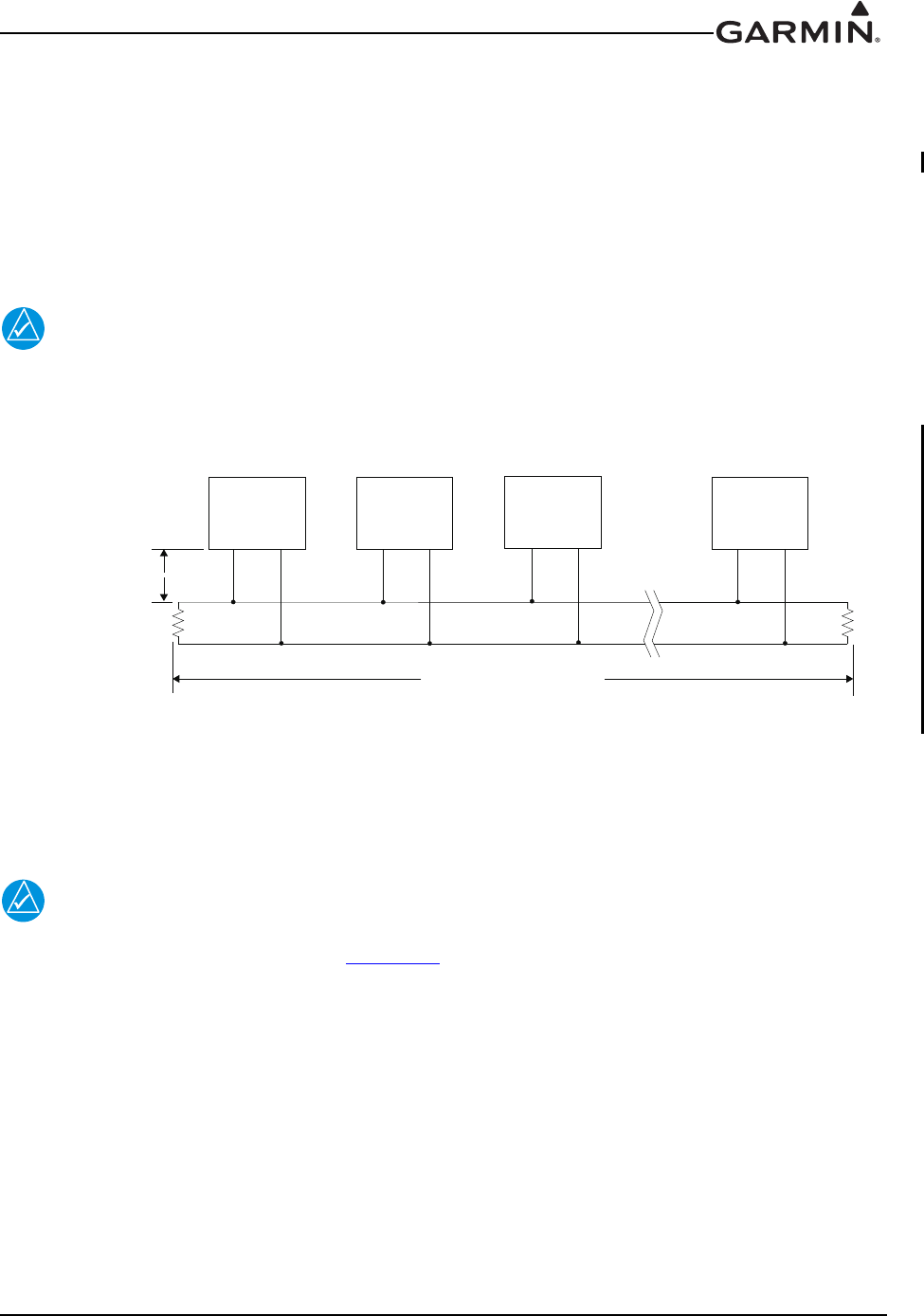
2.7.2 CAN Bus Considerations
The CAN (controller area network) bus (Figure 2-1) is an interface format used to establish
communication between several LRUs in the G3X system. Each end of the CAN bus “backbone” must be
terminated. Each node length (distance from CAN bus backbone to each LRU) must be 0.3 meter or less
in length (keeping the node lengths as short as practicable is recommended). There is no minimum node
length.
A GTR 200 can be connected in a G3X system that uses a GDU 37X or GDU 46X with CAN bus or
RS232, the CAN bus is preferred.
NOTE
Use only two CAN bus terminations per installation (even if provided more than two from
associated G3X installation kits). Using less than or more than two terminations (one at
each end of the backbone) will make the CAN bus unusable or unreliable.
Figure 2-1 CAN Bus Configuration
The following items should be considered when installing/removing/replacing LRU’s on the CAN bus:
1. CAN bus node connections must be made on the connector of each LRU that connects to the CAN
bus, do not tie CAN bus nodes from individual LRUs together into a single connection point.
2. Keep all node lengths as short as practicable, and allow only one ‘lengthy’ node if possible.
NOTE
The 120 Ω termination resistors described in the preceding paragraphs are “built-in” to
the termination method shown in Figure D-2. Do not install a separate “discrete” 120 Ω
resistor to terminate the CAN bus.
RLRL
CAN Bus Backbone
CAN HI
CAN LOW
(Node #1)
LRU
(Node #2)
LRU
(Node #3)
LRU
(Node #n)
LRU
Node Length
0.3 meter max.

190-01553-00 GTR 200 Installation Manual
Rev. G Page 2-6
2.8 Air Circulation and Cooling
The GTR 200 unit meets all requirements without external cooling. However, as with all electronic
equipment, lower operating temperatures extends equipment life. Reducing the operating temperature by
15° to 20°C (27° to 36°F) reduces the mean time between failures (MTBF).
Units tightly packed in the avionics stack heat each other through radiation, convection, and sometimes by
direct conduction. Even a single unit operates at a much higher temperature in still air than in moving air.
Fans or some other means of moving the air around electronic equipment are usually a worthwhile
investment.
2.9 Compass Safe Distance
After reconfiguring the avionics in the cockpit panel, if the unit is mounted less than 12 inches from the
compass, recalibrate the compass and make the necessary changes for noting correction data.
190-01553-00 GTR 200 Installation Manual
Rev. G Page 3-1
3 INSTALLATION PROCEDURES
3.1 Unpacking the unit
Carefully unpack the equipment and make a visual inspection of the unit for evidence of damage incurred
during shipment. If the unit is damaged, notify the carrier and file a claim. To justify a claim, save the
original shipping container and all packing materials. Do not return the unit to Garmin until the carrier has
authorized the claim.
Retain the original shipping containers for storage. If the original containers are not available, a separate
cardboard container should be prepared that is large enough to accommodate sufficient packing material to
prevent movement.
3.2 Wiring Harness Installation
Allow adequate space for installation of cables and connectors. The installer shall supply and fabricate all
cables. All electrical connections to the GTR 200 are made through one 37-pin D-sub standard density
connector (P2001) and one BNC connector for the antenna (P2002). Section 4 defines the electrical
characteristics of all input and output signals. Required connectors and associated hardware are supplied
with the connector kit (Table 2-3).
See Appendix D for examples of interconnect wiring diagrams. Construct the actual harnesses in
accordance with the aircraft manufacturer authorized interconnect standards. After the cable assemblies
are made, route the wiring bundle as appropriate. Use cable ties to provide strain relief for the coax and
cable assemblies.
The connector uses crimp contacts. Table 3-1 identifies crimp tools required to ensure consistent, reliable
crimp contact connections for the D-sub connector P2001. Table 3-2 identifies the contacts used for
P2001.
NOTE
Check wiring connections for errors before connecting to the GTR 200. Incorrect wiring
could cause internal component damage.
Table 3-1 Recommended Crimp Tools (or Equivalent)
Manufacturer Hand Crimping
Tool
20 – 24 AWG (P2001)
Positioner Insertion/
Extraction Tool
Military P/N M22520/2-01 M22520/2-08 M81969/1-02
Positronic 9507-0-0-0 9502-5-0-0 4711-2-0-0
AMP 601966-1 601966-5 91067-2
Daniels AFM8 K13-1 M81969/1-02
Astro 61517 615724 M81969/1-02
Table 3-2 Socket Contact Part Numbers
Supplier 20-24 AWG Socket Contact Part Number
Garmin Part Number 336-00022-02
Military Part Number M39029/63-368

190-01553-00 GTR 200 Installation Manual
Rev. G Page 3-2
3.3 Backshell Assembly
Refer to Appendix A for backshell and Shield Block ground assembly instructions.
3.4 Mounting Requirements
3.4.1 Rack Installation
Use the dimensions shown in Appendix C to prepare the mounting holes for the unit. You may also use
the GTR 200 unit mounting rack itself as a template for drilling the mounting holes.
1. Figure C-1 shows outline dimensions for the avionics rack for the unit. Install the rack in a
rectangular hole (or gap between units) in the instrument panel per Figure C-4. The lower-front lip
of the rack should be flush with, or extend slightly beyond the finished face of the aircraft panel.
NOTE
If the front lip of the mounting rack is behind the surface of the aircraft panel, the unit
connectors may not fully engage. See Figure C-4 for more information. Ensure that no
screw heads or other obstructions prevent the unit from fully engaging in the rack.
Exercise caution when installing the rack into the instrument panel. Deformation of the
rack may make it difficult to install and remove the unit.
2. Install the rack in the aircraft panel using six #6-32 flat head screws. The screws are inserted from
the inside through the holes in the sides of the rack.
3. Follow the steps listed in Figure C-3 to attach the backplate to the rack.
3.4.2 Unit Insertion and Removal
It may be necessary to insert the hex drive tool into the access hole and rotate the drive tool
counterclockwise until it completely stops in order to ensure correct position of the retention mechanism
prior to placing the unit in the rack. The unit is installed in the rack by sliding it straight in until it stops,
about 3/8 inch short of the final position. A 3/32-inch hex drive tool is then inserted into the access hole at
the bottom of the unit face. Rotate the hex tool clockwise while pressing on the bezel until the unit is
firmly seated in the rack.
To remove the unit from the rack, insert the hex drive tool into the access hole on the unit face. Rotate
counterclockwise until the unit is forced out about 3/8 inch and the hex drive tool completely stops. This
will allow the unit to be freely pulled from the rack.
Be sure not to over tighten the unit into the rack. The application of hex drive tool torque exceeding
15 in-lbs can damage the locking mechanism.

190-01553-00 GTR 200 Installation Manual
Rev. G Page 3-3
3.5 Antenna Installation and Connections
The GTR 200 requires a standard 50 vertically polarized antenna. Follow the antenna manufacturer’s
installation instructions for mounting the antenna.
The antenna should be mounted on a metal surface or a ground plane with a minimum area of 18 inches x
18 inches. Refer to Section 2.5.1 for installation location considerations.
3.5.1 Antenna Coaxial Cable Installation
The antenna coax cable should be made of RG-142B, RG-400 or a comparable quality 50 coax. Follow
the BNC connector manufacturer’s instructions for cable preparation/connector installation.
Check that there is ample space for the cabling and mating connectors. Avoid sharp bends in the antenna
cable, and routing near aircraft control cables. Route the COM antenna cable as far as possible away from
any GPS antenna cables.
Check for insertion loss and Voltage Standing Wave Ratio (VSWR). VSWR should be checked with an
in-line type VSWR/wattmeter inserted in the coaxial transmission line between the transceiver and the
antenna. The VSWR meter should be inserted as close to the transceiver as possible. When rack and
harness buildup is performed in the shop, the coax termination may be provisioned by using a 6-inch in-
line BNC connection. This would be an acceptable place to insert the VSWR meter. Any problem with
the antenna installation is most likely seen as high reflected power. A VSWR of 3:1 may result in up to a
50% loss in transmit power. VSWR at the low, mid and high end of the tuning range should be less than
3:1, for best performance VSWR should be less than 2:1. A high VSWR decreases the amount of power
radiated by the antenna and increases power supply current and heat dissipated by the radio when the radio
is transmitting.
190-01553-00 GTR 200 Installation Manual
Rev. G Page 3-4
3.6 Post Installation Configuration and Checkout Procedures
3.6.1 System Configuration Overview
This section contains checks to ensure the system is properly installed and functioning correctly as well as
instructions for configuring the GTR 200 to the specific installation. Follow the instructions in
Section 3.6.2 through Section 3.6.7.1 in order to complete all post installation configuration and checkout
procedures.
3.6.2 Mounting, Wiring, and Power Checks
Verify that all cables are properly secured and shields are connected to the shield block of the connectors.
Check the movement of the flight and engine controls to verify there is no interference between the cabling
and control systems. Ensure that all wiring is installed as described in Section 2.7.
Prior to powering up the unit, the wiring harness must be checked for proper connections to the aircraft
systems and other avionics equipment. Point to point continuity must be checked to expose any faults such
as shorting to ground. Any faults or discrepancies must be corrected before proceeding.
After accomplishing a continuity check, perform power and ground checks to verify proper power
distribution to the GTR 200. Any faults or discrepancies should be corrected at this time. Remove power
from the aircraft upon completion of the harness checkout.
The GTR 200 can be installed after completion of the continuity and power checks. The GTR 200 should
be installed into the rack and secured appropriately, as described in Section 3.4.2. The GTR 200 must be
connected to the wiring harness and antenna.
3.6.3 Configuration Mode
The configuration pages shown in this section reflect main software version 2.40 or later. Some
differences in operation may be observed when comparing the information in this manual to later software
versions. Refer to Figure 3-1 to identify knobs, buttons, and softkeys used in the configuration procedures.
Configuration mode is used to configure the unit settings for each specific installation. To access
configuration mode, remove power from the unit. With the unit turned off, press and hold the SMALL
Knob and apply power by turning the Power/Volume/Squelch Knob clockwise. Release the SMALL
Knob when the display activates, the Config Mode Home page will be displayed (Figure 3-2).
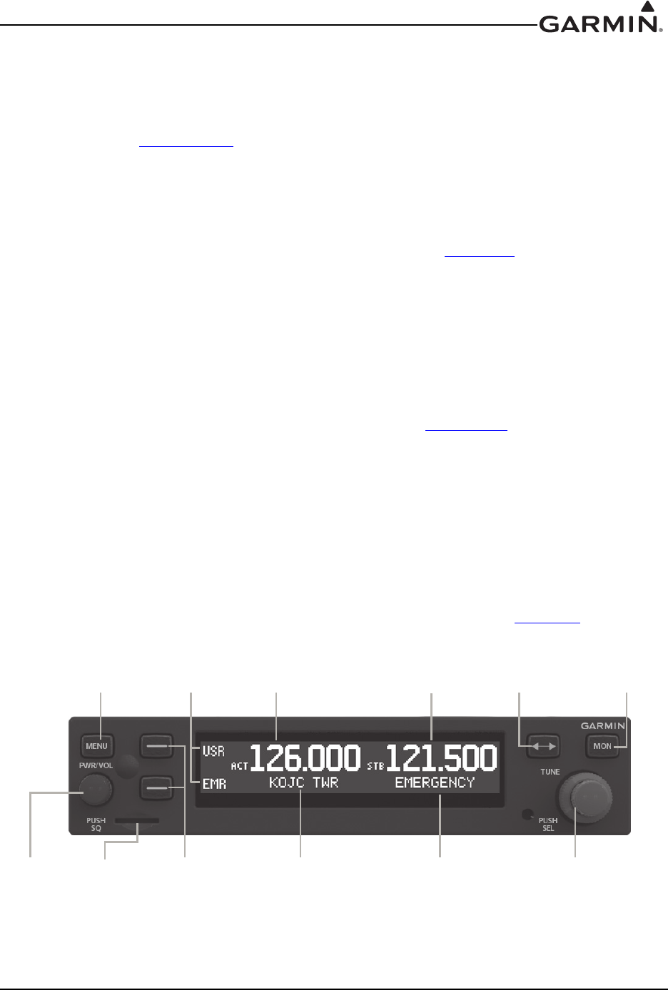
Figure 3-1 GTR 200 Front Panel
Menu
Button
Softkeys 1 (top)
and 2 (bottom)
Power/
Volume/
Squelch
Knob
Softkey
Labels Active
Frequency
Active
Frequency
Identifier
Standby
Frequency
Standby
Frequency
Identifier
Frequency
Transfer
Key
LARGE and SMALL
Knobs
Monitor
Standby
Frequency
Micro SD
Card Slot

190-01553-00 GTR 200 Installation Manual
Rev. G Page 3-5
3.6.4 Configuration Pages
The first page displayed in configuration mode (see Section 3.6.3) is the Configuration Mode Home page
(Figure 3-2). From the Configuration Mode Home page, turn the LARGE Knob to select the desired
subpage then press the SMALL Knob to display the subpage.
Figure 3-2 Configuration Mode Home Page
There are eight subpages available in configuration mode, each of these subpages is described in the
following sections:
• COM SETUP - See Section 3.6.4.2
• AUDIO SETUP - See Section 3.6.4.3
• SOFTKEY SETUP - See Section 3.6.4.4
• DISCRETE SETUP - See Section 3.6.4.5
• LIGHTING SETUP - See Section 3.6.4.6
• RS-232 STATUS - See Section 3.6.4.7
• HEADSET TESTS - See Section 3.6.5.1
• COM TESTS - See Section 3.6.5.2
• AUDIO TESTS - See Section 3.6.5.3

190-01553-00 GTR 200 Installation Manual
Rev. G Page 3-6
3.6.4.1 Default Settings
Table 3-3 lists the default values for the configuration mode settings.
Table 3-3 Configuration Default Settings
Page Setting Default Note
COM SETUP
SIDETONE 5
MIC GAIN 5
RF SQLCH 0
AUDIO SETUP INTERCOM ENABLED YES
RECEIVER OUT GAIN 100%
AUX 1 SQUELCH 30%
AUX 1 VOLUME 50%
AUX 1 MUTE (MUSIC) NO
AUX 2 SQUELCH 30%
AUX 2 VOLUME 50%
AUX 2 MUTE (MUSIC) NO
PILOT ON RIGHT SIDE NO
SOFTKEY SETUP
KEY 1 USER LIST
KEY 2 TUNE EMERGENCY
DISCRETE SETUP
DISC 1 PILOT ICS KEY
DISC 2 COPILOT ICS KEY
LIGHTING SETUP
LIGHTING SOURCE SENSOR
TIME CONSTANT 5.0/0.2
First value is photocell default;
Second value is lighting bus
default
MIN INPUT LEVEL 10%/21%
MIN BRIGHTNESS 10%/10%
MAX INPUT LEVEL 90%/86%
MAX BRIGHTNESS 100% N/A for photocell
OFF THRESHOLD 21%
OFF HYSTERESIS 0.1%
BUTTON OFFSET 10%
190-01553-00 GTR 200 Installation Manual
Rev. G Page 3-7
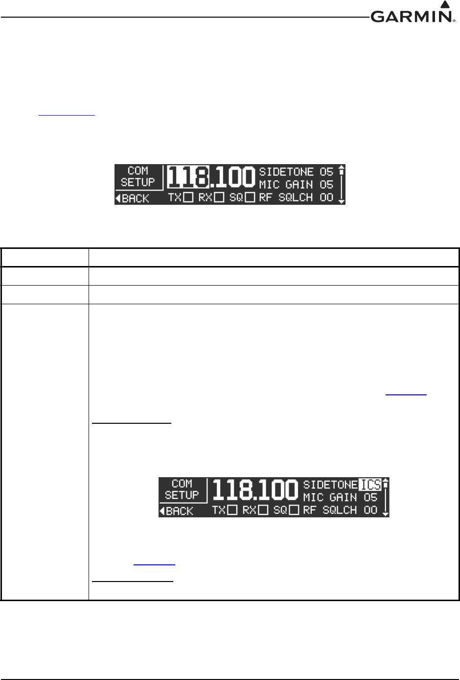
3.6.4.2 COM Setup Page
The COM Setup page (Figure 3-3) allows the installer to configure various transmit and receive settings as
listed in Table 3-4. For testing purposes, an “X” will appear in the appropriate TX, RX, and SQ
checkboxes when the GTR 200 is transmitting, receiving, or the squelch is overridden or open (‘open’
squelch is defined as when the squelch is overridden and audio is heard).
Refer to Section 3.6.4 to select the COM Setup Page. Use the LARGE Knob to scroll through the listed
functions, then use the SMALL Knob to adjust the setting of the function. After the setting has been
changed, turn the LARGE Knob to move the cursor to another function.
Figure 3-3 COM Setup Page
Table 3-4 COM Setup Page Selections
Selection Description
Frequency (MHz) Set frequency from 118-136 MHz.
Frequency (kHz) Set frequency from 0-975 kHz in 25 kHz increments.
SIDETONE
This setting controls the volume of the sidetone audio for the unit during PTT, and is
adjusted to correct either low or high sidetone volume. Increasing the setting
increases the sidetone volume. Sidetone can be set from 0 to 10, a setting of 5
(default) represents the factory calibration.
Sidetone audio is routed to headset audio and to received audio out, and is generally
output to an audio control panel.
The Intercom Enable/Disable setting on the Audio Setup Page (see Table 3-5)
affects the sidetone per the following:
Intercom Enabled:
Sidetone volume may also be linked to the ICS (intercom) volume. This is
accomplished by selecting the Sidetone setting one turn counter clockwise from ‘00’
setting, ‘ICS’ will be displayed (Figure 3-5). Intercom volume is adjustable in normal
mode (see Pilots Guide).
Figure 3-4 ICS Sidetone Selection
Sidetone audio that is sent to the received audio output (see Receiver Out Gain
setting in Table 3-5) is the same volume as sidetone audio sent to the headset.
Intercom Disabled:
Sidetone audio is only sent to received audio output (not to the headset).
190-01553-00 GTR 200 Installation Manual
Rev. G Page 3-8
MIC GAIN
Increasing or decreasing this setting, increases or decreases the transmit
microphone gain respectively. Mic gain can be set from 0 to 10. A setting of 5
(default) represents the factory calibration, most headsets/microphones should work
fine at this setting. Generally the mic gain setting should not be adjusted unless the
pilot consistently gets reports that the transmitter sounds “weak”. Most often, this
setting is adjusted to compensate for “weak” or low output microphones. The
transmit sidetone volume is affected by the mic gain setting, so an adjustment of the
sidetone setting may be needed after adjusting the mic gain setting.
RF SQLCH
Increasing this setting increases the signal level required to break squelch. Receiver
squelch can be set from 0-10, a setting of 0 (default) represents the factory
calibration.
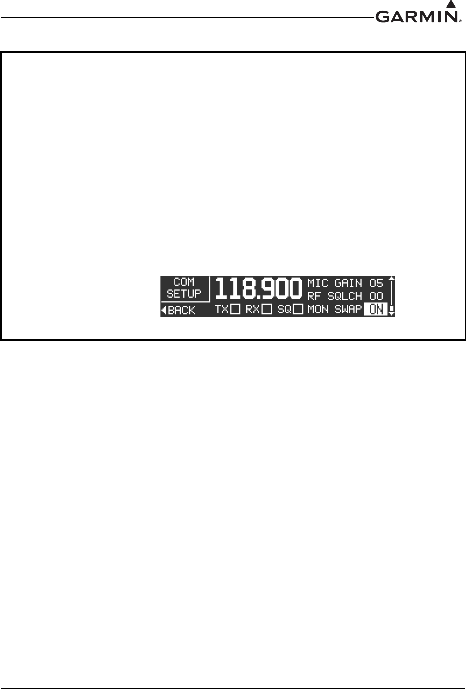
MON SWAP
This setting affects how the monitor function acts when pressing the Frequency
Transfer Key (in addition to swapping the Active and Standby frequencies).
Setting to ON (Figure 3-5) will keep the Monitor feature ON when pressing the
Frequency Transfer Key.
Setting to OFF will turn off the Monitor feature when the Frequency Transfer Key is
pressed
Figure 3-5 MON Swap Selection
Table 3-4 COM Setup Page Selections
190-01553-00 GTR 200 Installation Manual
Rev. G Page 3-9
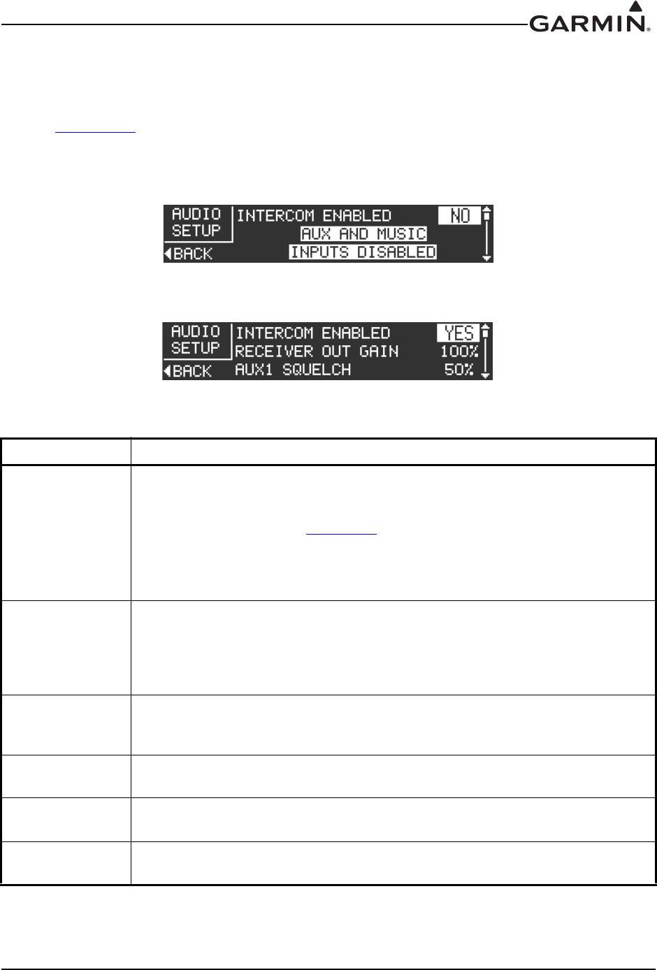
3.6.4.3 Audio Setup
The Audio Setup page (Figure 3-6, Figure 3-7) allows the installer to configure the various audio settings
listed in Table 3-6.
Refer to Section 3.6.4 to select the Audio Setup Page. Use the LARGE Knob to scroll through the listed
functions, then use the SMALL Knob to adjust the setting of the function. After the setting has been
changed, turn the LARGE Knob to move the cursor to another function.
Figure 3-6 Audio Setup Page (AUX and Music Disabled)
Figure 3-7 Audio Setup Page (AUX and Music Enabled)
Table 3-5 Audio Setup Page Selections
Selection Description
INTERCOM
(ENABLED/
DISABLED)
Turns the intercom function on or off. When intercom is disabled, music and
auxiliary inputs are also disabled. Intercom Disabled is the suggested setting
when the GTR is being wired to an audio panel. This setting may also affect
Sidetone functionality, see Section 3-4.
Using a headset that has a MIC Telephone switch option may disable the intercom
function. To restore intercom function, turn the MIC Telephone switch to the Off
position, and power cycle the GTR200.
RECEIVER OUT
GAIN
When the intercom is enabled, RECEIVER AUDIO OUT (pin 10) will output
everything the pilot hears in the headset ear speakers with the exception of music
audio. If RECEIVER AUDIO OUT is used as the source of audio to a recording
device then adjust the RCVR OUT GAIN setting for desired audio level at the
recording device.
AUX SQ 1 & 2
AUX SQ prevents low level noise from being passed to the headset ear speakers.
Adjust the AUX SQ level so the audio background noise is muted. Warning,
adjusting the AUX SQ to a high level may squelch the desired audio.
AUX VOL 1 & 2 If AUX1 or AUX2 inputs are used these settings allow adjusting the sensitivity of
the AUX inputs.
AUX MUTE
(MUSIC) 1 & 2
This setting when enabled, will mute the music input if AUX1 or AUX2 input levels
are sufficient to break AUX SQ.
PILOT ON RIGHT
SIDE
Select YES or NO to select pilot location. When YES is selected the copilot is
positioned to the left of the pilot for 3D audio processing.
190-01553-00 GTR 200 Installation Manual
Rev. G Page 3-10
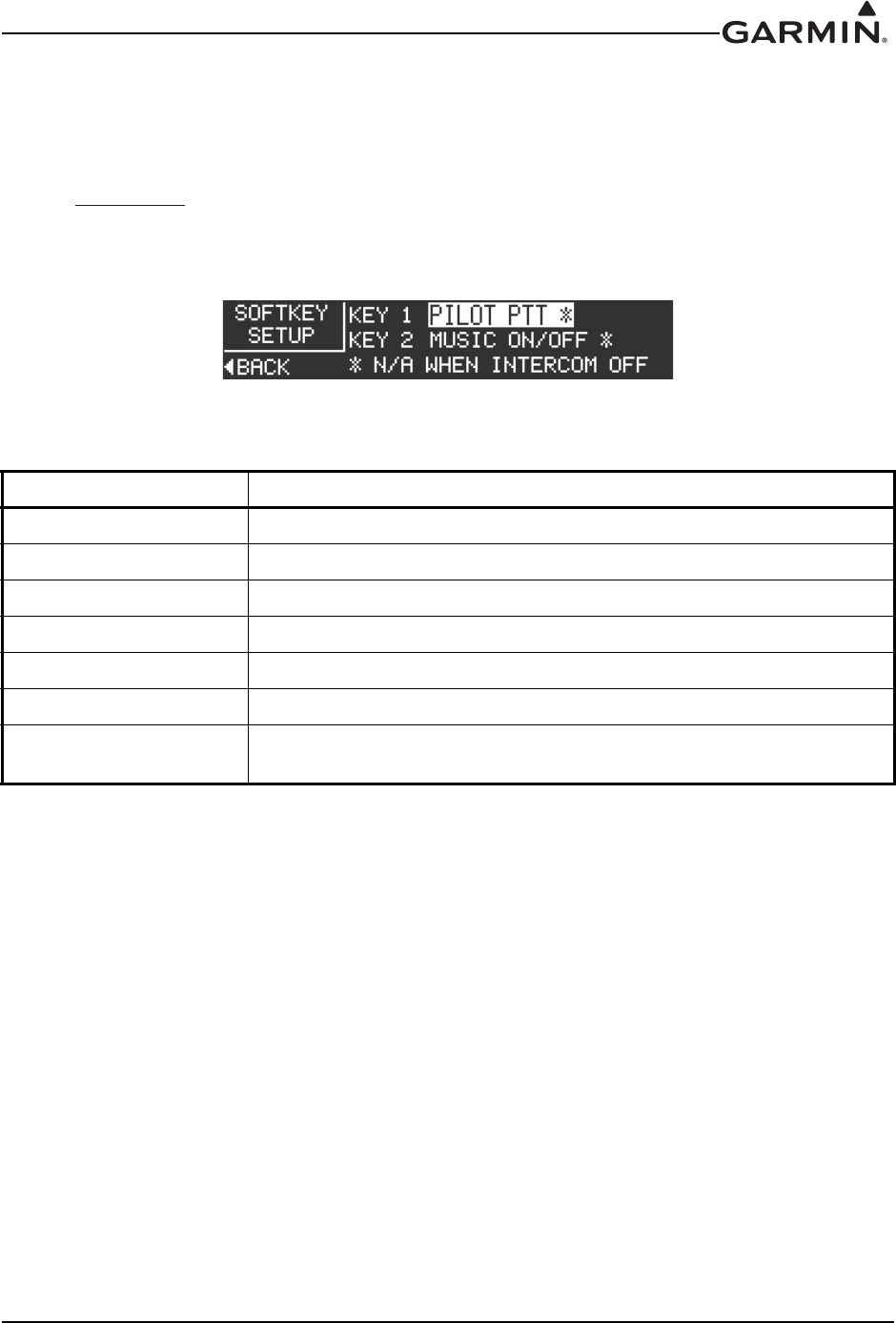
3.6.4.4 Softkey Setup Page
The Softkey Setup page (Figure 3-8) allows the installer to configure the operation of Softkey 1 (top) and
Softkey 2 (bottom), per the options listed in Table 3-6. Note that both softkeys cannot select the same
function (except Disabled).
Refer to Section 3.6.4 to select the Softkey Setup Page. Use the LARGE Knob to scroll through the listed
functions, then use the SMALL Knob to adjust the setting of the function. After the setting has been
changed, turn the LARGE Knob to move the cursor to another function.
Figure 3-8 Softkey Setup Page
Table 3-6 Softkey Setup Page Selections
Selection Description
DISABLED Disables softkey.
PILOT PTT* Radio transmits pilot MIC audio when key pressed.
PILOT ISOLATION* Isolates pilot from copilot and music.
MUSIC ON/OFF* Turns music input on/off.
USER LIST Moves directly to user frequency list menu.
TUNE EMERGENCY Sets active frequency to emergency frequency, 121.500.
USR FREQ MEM CYCLE Allows one of the softkeys to be used to cycle through stored user COM
frequencies.
*Indicates that function is not available when the intercom is set to off
190-01553-00 GTR 200 Installation Manual
Rev. G Page 3-11
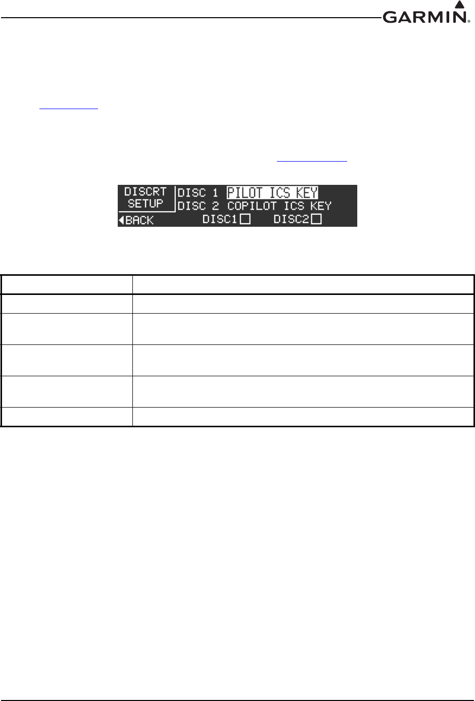
3.6.4.5 Discrete Setup Page
The Discrete Setup page (Figure 3-9) allows the installer to configure the operation of the discrete inputs
per the options listed in Table 3-7. It is not necessary to connect the discrete inputs, if a discrete input is
used it is normally connected to a momentary contact pushbutton.
Refer to Section 3.6.4 to select the Discrete Setup Page. Use the LARGE Knob to scroll through the listed
functions, then use the SMALL Knob to adjust the setting of the function. After the setting has been
changed, turn the LARGE Knob to move the cursor to another function. Note that both discrete inputs
cannot select the same function (except Disabled). For testing purposes, an “X” will appear in the DISC 1
and/or the DISC 2 checkbox when the input(s) are active (see Section 3.6.5.5).
Figure 3-9 Discrete Setup Page
Table 3-7 Discrete Setup Page Selections
Selection Description
DISABLED Discrete input is disabled.
PILOT ICS KEY Discrete input activates the pilot ICS function. Auto squelch and manual
squelch are overridden when the PILOT ICS KEY is asserted.
COPILOT ICS KEY Discrete input activates the copilot ICS function. Auto squelch and
manual squelch are overridden by COPILOT ICS KEY selection.
FREQ SWAP BTN Discrete input activates the frequency swap function (a beep tone is
sounded).
USR FREQ CYCLE BTN Discrete input activates cycle through stored user COM frequencies.
190-01553-00 GTR 200 Installation Manual
Rev. G Page 3-12
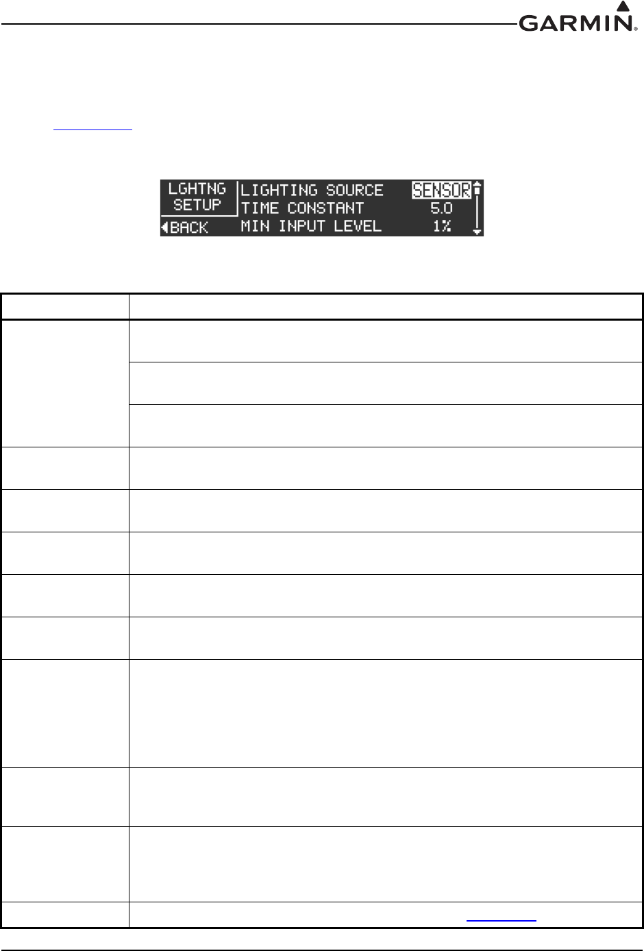
3.6.4.6 Lighting Setup Page
The Lighting Setup page (Figure 3-10) allows the installer to configure the operation of the bezel keys and
display lighting, per the options listed in Table 3-8.
Refer to Section 3.6.4 to select the Lighting Setup Page. Use the LARGE Knob to scroll through the listed
functions, then use the SMALL Knob to adjust the setting of the function. After the setting has been
changed, turn the LARGE Knob to move the cursor to another function.
Figure 3-10 Lighting Setup Page
Table 3-8 Lighting Setup Page Selections
Selection Description
LIGHTING
SOURCE
SENSOR - Bezel keys and display lighting is controlled by the light sensor
(photocell) on the front panel.
14V - Configures the lighting bus source voltage to 14V. Bezel keys and display
lighting is controlled by the input voltage (0-14 VDC) on pin 3.
28V - Configures the lighting bus source voltage to 28V. Bezel keys and display
lighting is controlled by the input voltage (0-28 VDC) on pin 3.
TIME CONSTANT Adjusts the speed (in seconds), that the brightness level responds to changes in
the input level.
MIN INPUT
LEVEL
Sets the lower input level required to turn the backlighting on to the percentage of
brightness set by the Min Brightness setting.
MIN
BRIGHTNESS Sets the minimum brightness of the display backlight.
MAX INPUT
LEVEL
Sets the upper input level required to turn the backlighting on to the percentage of
brightness set by the Max Brightness setting.
MAX
BRIGHTNESS Sets the maximum brightness of the display backlight.
OFF
THRESHOLD
Sets the lighting bus off threshold level. At the threshold level, the backlighting is
turned on per the Min Brightness setting. Below the threshold level, the
backlighting defaults to a Backlight Level of 100%. If the value is set to 0%, the
value will be ignored and the display brightness will remain at the Min Brightness
level for any input level between 0% and the Min Brightness level. This setting is
not available when Lighting Source is set to SENSOR.
OFF
HYSTERESIS
Sets the range that the 100% Backlight Level is in effect after the input level rises
above the Off Threshold. This setting is not available when Lighting Source is set
to SENSOR.
BUTTON
OFFSET
Adjusts the bezel backlight to be brighter than display backlight Bezel lighting
appears dimmer than display lighting when set to the same brightness level
(default offset is 4%). Bezel backlight can brightened by raising the BUTTON
OFFSET value.
VIEW GRAPH Press the SMALL Knob to display the Lighting Graph (Figure 3-11).
190-01553-00 GTR 200 Installation Manual
Rev. G Page 3-13
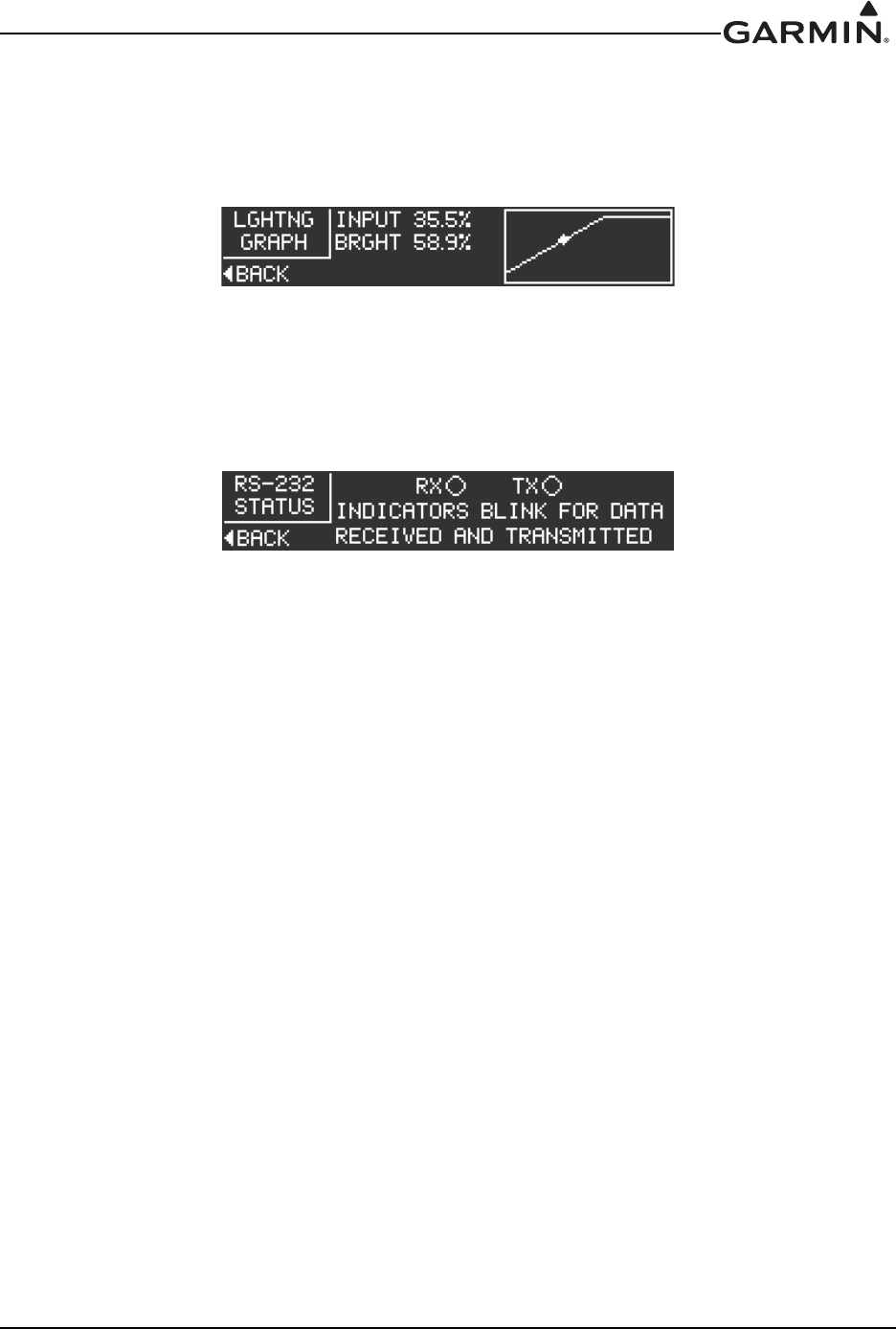
The Lighting Graph page Figure 3-11 graphically displays the input (voltage or percentage of lighting
sensor) and brightness in real time. Brightness level is displayed as the vertical (Y) axis, and input level is
displayed as the horizontal (X) axis. The graph changes according to the backlight control settings, and the
lighting source input level.
Figure 3-11 Lighting Graph
3.6.4.7 RS-232 Status Page
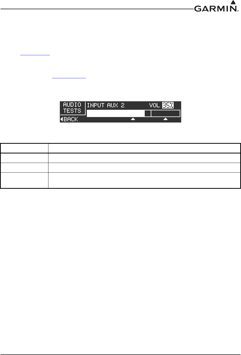
The RS-232 Status page (Figure 3-12) allows the installer to verify if RS-232 data is being received or
transmitted. The indicators next to both ‘RX’ and ‘TX’ will blink if data is being transmitted or received.
The RS-232 Status page is an information only page, there are no user-selectable settings.
Figure 3-12 RS-232 Status Page

190-01553-00 GTR 200 Installation Manual
Rev. G Page 3-14
3.6.5 Unit Ground Checks (Configuration Mode)
Refer to Section 3.6.3 to put the GTR 200 into configuration mode.
3.6.5.1 Headset Tests Page
The Headset Tests page (Figure 3-13) allows the installer to test the operation of the headset outputs.
Refer to Section 3.6.4 to select the Headset Tests Page.
Figure 3-13 Headset Tests Page
Stereo headsets with the stereo setting selected must be used with 3D audio. Stereo headsets are shipped
set to mono. Make sure the headsets used for this test are set to the stereo position.
A true mono headset will work correctly with the GTR 200, but only mono audio will be heard and 3D
audio will not be available. The GTR 200 will detect the mono headset and automatically switch to mono
operation. Refer to Appendix D-1 Note 4, MONO PLUG. A mono headset plug can be identified by the
absence of the RING. Perform the below procedure to verify proper headset configuration.
1. Connect a stereo headset to the pilot headset position.
2. Move to the HEADSET TEST subpage.
3. Verify that none of the HS SHORT checkboxes are checked.
a) If the HS SHORT L checkbox is checked it is likely that there is an installation wiring
problem.
b) If the HS SHORT R checkbox is checked it is likely that a mono headset is plugged in or
there is an installation wiring problem.
c) If both the HS SHORT L and R checkboxes are checked it is likely that a stereo headset set
to mono is plugged in.
d) If any of the HS SHORT checkboxes are checked, and no headset is plugged in, check for an
installation wiring problem.
4. Use the SMALL Knob to move through the TEST TONE positions. The positions are:
a) PIL LEFT – A tone should be heard in the left ear speaker of the pilot headset.
b) PIL RIGHT – A tone should be heard in the right ear speaker of the pilot headset.
c) COP LEFT – A tone should be heard in the left ear speaker of the copilot headset.
d) COP RIGHT – A tone should be heard in the right ear speaker of the copilot headset.
5. Verify that the test tone is heard in the correct headset ear speaker and the tone is not heard in any
other position.
6. Repeat the test for the copilot headset position.

190-01553-00 GTR 200 Installation Manual
Rev. G Page 3-15
3.6.5.2 COM Tests Page
The COM Tests page (Figure 3-14) allows the installer to test the operation of the COM functions.
Refer to Section 3.6.4 to select the COM Tests Page.
Figure 3-14 COM Tests Page
Perform the below procedure to verify proper COM configuration.
1. Connect a headset to the pilot headset jacks.
2. Select the COM TESTS subpage.
3. Verify none of the checkboxes are checked. The checkboxes are:
a) TX – Indicates the radio is transmitting.
b) RX – Indicates the radio is receiving.
c) SQ – Indicates the radio squelch is overridden. Radio squelch can be overridden by pushing
the volume knob.
d) LO VOLT - Indicates the radio input voltage is low. The radio will reduce TX power or
stop transmitting completely depending on the voltage level.
e) HI TEMP – Indicates the transmitter temperature is high. If transmitter temperature is high
the radio will reduce TX power until the temperature lowers.
f) TX AMPS – This is not a checkbox. This indicates how much current (in Amps) is supplied
to the transmitter. When the GTR 200 is transmitting the current draw will be approximately
3.0 Amps under ideal load conditions. When the GTR 200 is not transmitting the current
draw will be around 0.01 Amps.
4. If the LO VOLT checkbox is checked this indicates a low battery condition or wiring fault that is
preventing the radio from receiving proper voltage. Correct this condition before proceeding with
this test.
5. Select a frequency that is transmitting. An ATIS, ASOS, or other continuously transmitting
frequency is a good choice. Frequency tuning works differently in configuration mode. The
SMALL Knob changes the highlighted frequency field and the LARGE Knob moves the
highlighted field.
6. Verify the RX checkbox is checked and the received audio can be heard in the headset.
7. Select a frequency that is safe for transmission. The antenna and coaxial cable must be properly
connected to the radio before attempting to transmit.
8. Key the transmitter and verify the TX checkbox is checked while transmitting. If the checkbox
does not check there is a wiring fault. If the checkbox is always checked there is a wiring fault.
9. If the radio is tuned to a frequency that is appropriate for a radio check, one can be performed as
part of this test.
10. If the copilot position is wired for transmission repeat the test for the copilot position.
190-01553-00 GTR 200 Installation Manual
Rev. G Page 3-16
3.6.5.3 Audio Tests Page
The Audio Tests page (Figure 3-15) and the following procedure will ensure that the audio level into the
GTR 200 AUX/Music inputs (listed in Table 3-9) is set to the ideal level for best sound quality and noise
rejection. It will also ensure the audio level heard in the pilot headset is at the desired level.
Refer to Section 3.6.4 to select the Audio Tests Page.
The solid bar represents the average signal level and the vertical line represents the peak level. If the AUX
levels are not set correctly, alerts connected to the AUX inputs may be partially or completely muted. The
AUX SQUELCH (see Section 3.6.4.3) can be adjusted if the AUX input level cannot be set to the proper
range. The AUX SQUELCH will not require adjustment from the 30% setting if the input level is set to
the proper range.
Figure 3-15 Audio Tests Page
1. Turn on the audio source connected to the AUX/Music input(s).
2. Place the GTR 200 in CONFIG MODE.
3. Select the AUDIO TESTS subpage.
4. Use the LARGE and SMALL Knobs to select the audio source.
5. With the audio source active adjust the audio source output level so the average level is between
the two marks on the level bar.
6. Use the LARGE Knob to move to the VOL selection.
7. While wearing a headset use the SMALL Knob to adjust the headset volume to the desired level.
8. Repeat for any other AUX/Music inputs.
Table 3-9 Audio Tests Source Selections
Selection Description
OFF No audio source selected.
AUX 1 & 2 Auxiliary inputs 1 and 2. These inputs are not muted.
MUSIC LEFT
AND RIGHT Stereo music input. This input can be muted.
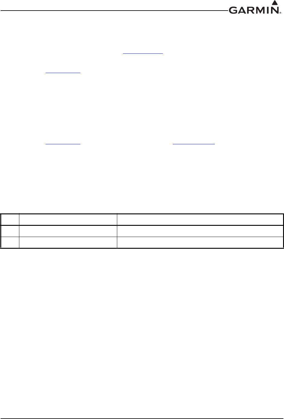
190-01553-00 GTR 200 Installation Manual
Rev. G Page 3-17
3.6.5.4 Lighting Bus Interface Check
The display and bezel key backlighting on the GTR 200 can track an external lighting/dimmer bus input
and use it to vary the display and bezel key backlight levels accordingly. This check is only applicable if
Lighting Source (on the Lighting Setup Page, Section 3.6.4.6) is set to 14V or 28V, and verifies that the
interface is connected correctly.
1. Refer to Section 3.6.4 to select the Lighting Setup Page.
2. Ensure the lighting bus input is set to its minimum setting.
3. Slowly vary the input lighting bus level. Verify that the display brightness tracks the lighting bus
setting. Continue to maximum brightness and verify proper operation.
3.6.5.5 Discrete Input Checkout
If one or both discrete inputs (Table 3-10) are connected, the wiring is checked using the following
procedure.
1. Refer to Section 3.6.4 to select the Discrete Setup Page (Section 3.6.4.5).
2. While the momentary contact pushbutton(s) are not being pressed (inputs are not grounded), verify
the DISC 1 and DISC 2 check boxes are not checked. If one or both boxes is checked, the wiring
is likely the cause of the failure.
3. Activate the DISC 1 and/or DISC 2 input by pressing the associated momentary contact
pushbutton (inputs are grounded). Verify the appropriate checkbox is checked. If the checkbox is
not checked the wiring is likely the cause of the failure.
Table 3-10 Discrete Inputs
Pin Pin Name Description
2DISC 1 Configurable discrete active low input 1
22 DISC 2 Configurable discrete active low input 2

190-01553-00 GTR 200 Installation Manual
Rev. G Page 3-18
3.6.6 Unit Ground Checks (Normal Mode)
3.6.6.1 TX Interlock Checkout
Connect pins 4 and 5 per Appendix D.
3.6.6.2 Antenna Check
If desired, the antenna VSWR can be checked using an inline wattmeter in the antenna coaxial using
frequencies near both ends of the band. The VSWR should be less than 2:1. A VSWR of 2:1 will cause a
drop in output power of approximately 12%.
3.6.6.3 Receiver/Transmitter Check
Tune the unit to a local VHF frequency and verify the receiver output produces a clear and understandable
audio output. Verify the transmitter functions properly by contacting another station and getting a report
of reliable communications.
3.6.6.4 RS-232 Serial Interface Checks
The interfaces to RS-232 equipment such as the G3X sources should be checked as follows:
1. Operate the connected serial remote tune source and the GTR 200 in normal mode.
2. Ensure that the remote source, if capable, is able to display data from the GTR 200.
3. Ensure that the remote source, if capable, is able to tune the GTR 200.
Table 3-11 TX Interlock Connections
Pin Pin Name Description
4TX INTERLOCK OUT
Active low output that indicates the GTR 200 is transmitting.
This output is normally connected to the TX INTERLOCK IN
of other COM radios installed in the aircraft.
5TX INTERLOCK IN
Active Low Input that ‘desenses’ (protects) the GTR 200
receiver when another communications radio is
transmitting. This input comes from another communication
radio's interlock output or MIC KEY line.

190-01553-00 GTR 200 Installation Manual
Rev. G Page 3-19
3.6.7 Flight Checks
3.6.7.1 COM Flight Check
After the installation is complete, perform the following required flight checks to ensure satisfactory
transceiver performance.
Check the communications transceiver at a range of at least 50 nautical miles: (This check verifies unit
receiver sensitivity test and transmitter range)
1. Maintain an altitude of 5000 ft AGL.
2. Select the frequency of a ground station facility at a range of at least 50 nautical miles.
3. Verify that communication (RX and TX) can be established with that facility.
Check the communications receiver by receiving transmission from a ground station in close proximity
(range of less than 10 nautical miles): (This check verifies that the receiver has a high signal to noise ratio
when receiving a strong signal.)
1. Select the frequency of a ground station facility at a range of less than 10 nautical miles.
2. Make sure the received audio from that station is clear (no background electrical noise).
3. If possible, perform the preceding steps 1 and 2 for frequencies in the high (~136.XXX MHz), mid
(~127.XXX MHz), and low (~118.XXX MHz) range of the GTR 200.
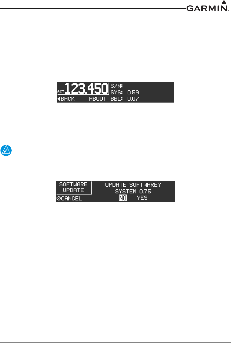
190-01553-00 GTR 200 Installation Manual
Rev. G Page 3-20
3.7 Unit Software
3.7.1 Checking Software Version
The GTR 200 comes pre-loaded with system software. However, if the software is out of date, it is
recommended that current software be loaded from a micro SD card into the GTR 200.
The current software version can be displayed in normal operation mode by pressing the MENU Key, then
highlighting SETUP and pressing the SMALL Knob. The serial number, system software version, and
boot block software version are displayed.
Figure 3-16 About Page
3.7.2 Software Update
The Software Update page (Figure 3-17) allows the installer to load unit software using a micro SD
software loader card. Section 3.7.3 lists instructions on creating the loader card
NOTE
Garmin recommends the use of a Sandisk® brand 4GB micro SD card for updating unit
software.
Figure 3-17 Software Update Page
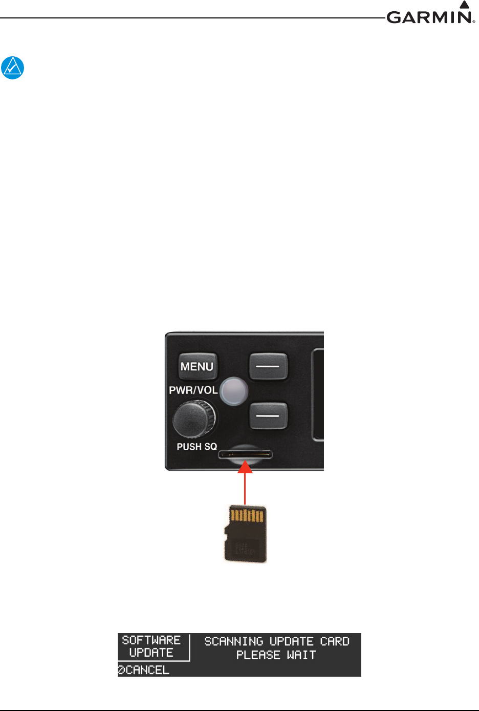
190-01553-00 GTR 200 Installation Manual
Rev. G Page 3-21
3.7.3 Creating a Software Loader Micro SD Card
NOTE
Note: The application to create a loader card requires Windows 2000, XP, Vista, or
Windows 7. There is no Mac support at this time.
1. Go to the GTR 200 web page on Garmin’s web site.
2. Download the GTR 200 System software to your PC.
3. Ensure that you have a micro SD card (Garmin recommends a Sandisk® brand 4GB micro SD
card) connected to the PC in the micro SD card slot or by using an SD card adapter that allows a
micro SD card to be used.
4. Run the executable file that was downloaded and follow the prompts on the screen to create the
software loader card.
5. After the card has been created, select finish to complete the process.
6. Remove the card from the slot. The loader card is now ready to use.
3.7.4 Loading Software to the GTR 200
To load software to the GTR 200, ensure that the unit is turned off.
1. Insert a micro SD card with pins facing up into the slot on the unit face as shown in Figure 3-18
Figure 3-18 Micro SD Insertion
2. Power on the GTR 200.
3. The GTR 200 will automatically check the micro SD card for updated software.
Figure 3-19 Software Update Page - Scanning Card
MICRO SD CARD
PINS FACING UP
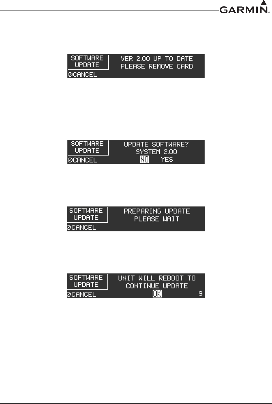
190-01553-00 GTR 200 Installation Manual
Rev. G Page 3-22
a) If the software on the SD card matches the software in the GTR 200 the display will show
“VER X.XX UP TO DATE PLEASE REMOVE CARD”. Note that this screen (Figure 3-
20) will also be displayed following a successful software update and reboot.
Figure 3-20 Software Update Page - No Update Found
b) The micro SD card can be removed or the cancel soft key can be pressed to return the
GTR 200 to normal operation. If the cancel soft key is used, the same screen will be
displayed at the next power cycle.
4. If the micro SD card contains updated software the GTR 200 will prompt to load the software.
Figure 3-21 Software Update Page - Update Software?
5. To load software select YES and press the SMALL Knob. The GTR 200 will prepare to update the
software.
Figure 3-22 Software Update Page - Preparing Update
6. Once preparation is complete the GTR 200 will reboot. Reboot will happen automatically after a
short time or reboot can be manually initiated by selecting OK and pressing the SMALL Knob.
Figure 3-23 Software Update Page - Unit Will Reboot
7. Do not remove power until the software update has completed. After the reboot the software
update process is complete and the unit will display “No Update Found Please Remove Card”. the
micro SD card may be removed at this time.
3.8 Continued Airworthiness
Other than for regulatory checks, maintenance of the GTR 200 is ‘on condition’ only. Periodic
maintenance of the GTR 200 is not required. Instructions for Continued Airworthiness (ICA) are not
required for this product under 14 CFR Part 21 since the GTR 200 has received no FAA approval or
endorsement.

190-01553-00 GTR 200 Installation Manual
Rev. G Page 4-1
4 CONNECTOR PINOUT INFORMATION
4.1 Pin Function List
4.1.1 J2001 Connector
Figure 4-1 J2001 Looking at rear of unit
Table 4-1 J2001 Connector
Pin Pin Name I/O
1AIRCRAFT POWER In
2DISC 1* In
3LIGHTING BUS IN In
4TX INTERLOCK OUT Out
5TX INTERLOCK IN* In
6CAN BUS LO --
7CAN BUS HI --
8ID IN In
9AUX MONO IN 2 In
10 RECEIVER AUDIO OUT HI Out
11 COPILOT HS RIGHT Out
12 COPILOT HS LEFT Out
13 PILOT HS RIGHT Out
14 PILOT HS LEFT Out
15 COPILOT PTT* In
16 COPILOT MIC IN In
17 PILOT MIC IN In
18 MUSIC IN RIGHT In
19 MUSIC IN LEFT In
20 AIRCRAFT GROUND --
21 SPARE --
22 DISC 2* In
23 RS232 OUT Out
24 RS232 IN In
25 CAN TERM B --
26 CAN TERM A --
27 ID LO --
28 AUX 2 LO --
*Indicates Active Low
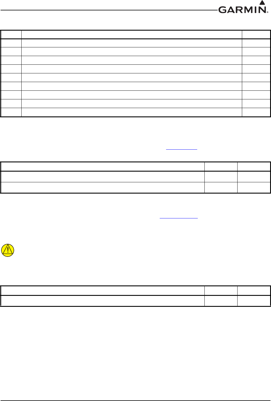
190-01553-00 GTR 200 Installation Manual
Rev. G Page 4-2
4.2 Power
Pins 1 & 20 supply power to the GTR 200. Refer to drawings in Appendix D for power and ground wire
gauges.
4.3 Lighting Bus
The lighting bus is configurable for either 14 or 28 Vdc input (Section 3.6.4.6). This pin is an input that
uses an external reference voltage to control the brightness of the display and backlight (it is not used to
power the lighting). The input impedance is approximately 163 k.
CAUTION
Connecting the lighting bus to an incorrect pin can cause damage to the unit that will
require return to the factory for repair. Make sure that the lighting bus is connected to the
correct pin and does not short to any adjacent pins prior to applying power to the unit.
29 RECEIVER AUDIO LO --
30 COPILOT HS LO --
31 AUX 1 LO --
32 AUX MONO IN 1 In
33 PILOT HS LO --
34 COPILOT MIC LO --
35 PILOT PTT* In
36 PILOT MIC LO --
37 MUSIC LO In
*Indicates Active Low
Pin Name Pin I/O
AIRCRAFT POWER 1In
AIRCRAFT GROUND 20 --
Pin Name Pin I/O
LIGHTING BUS IN 3In
Table 4-1 J2001 Connector
Pin Pin Name I/O
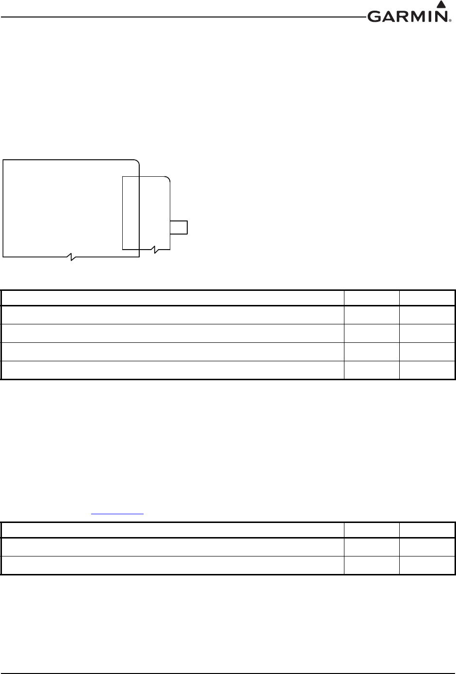
190-01553-00 GTR 200 Installation Manual
Rev. G Page 4-3
4.4 CAN Bus
The CAN bus conforms to the BOSCH standard for Controller Area Network 2.0-B, and complies with
ISO 11898. Pins 25 and 26 are used to terminate the CAN bus. The CAN bus on J2001 is used for
communications between G3X system LRUs, and is the preferred connection method to G3X systems.
The GTR 200 should only be terminated if it is located at the end of the CAN bus. To terminate the CAN
bus at the GTR 200, short pins 25 and 26 together, this creates a 120 ohm termination internal to the
GTR 200 LRU. If installed, the jumper between pins 25 and 26 should be 3" or less, and contained
completely within the connector backshell.
Figure 4-2 CAN Bus Termination for GTR 200
4.5 Unit ID
The Unit ID pins are used for setting up the GTR 200 to be identified in the G3X system when connected
by the CAN bus as either a COM 1 or a COM 2 radio.
For installations with dual GTR 200 radios, leave pin 8 open to identify the GTR200 as COM 1. Connect
pin 8 to pin 27 on the second GTR 200 to identify it as COM 2. If installed, the jumper between pins 8 and
27 should be 3" or less, and contained completely within the connector backshell.
For single installations do not connect pin 8 to pin 27 (leave open) to identify the GTR 200 as COM 1.
Refer to drawings in Appendix D for ID connections.
Pin Name Pin I/O
CAN BUS LO 6I/O
CAN BUS HI 7I/O
CAN TERM B 25 --
CAN TERM A 26 --
Pin Name Pin I/O
ID IN 8In
ID LO 27 --
NOTE: JUMPER (BETWEEN PINS 25 & 26) REQUIRED NOTE: JUMPER (BETWEEN PINS 25 & 26) REQUIRED
WHEN GTR 20/200 IS LOCATED AT END OF CAN BUSWHEN GTR 20/200 IS LOCATED AT END OF CAN BUS
CAN_TERM_A 25CAN_TERM_A 25
CAN_TERM_B 26CAN_TERM_B 26
GTR 20/200GTR 20/200
CAN BUS HI 7CAN BUS HI 7
CAN BUS LO 6CAN BUS LO 6
P2001P2001J2001J2001
190-01553-00 GTR 200 Installation Manual
Rev. G Page 4-4
4.6 Serial Data – RS-232
Section 4.6.1.1 details the formats that can be selected for the RS-232 channel.
NOTE
The GTR 200 can be installed into the G3X system using an RS-232 or CAN bus
(preferred) connection.
4.6.1 NMEA Format
4.6.1.1 Legacy NMEA Support
The GTR 200 maintains backwards compatibility with legacy SL30/SL40 NMEA commands ($PMMRC
and $PMMRV) as they apply to GTR 200 functionality. Refer to Appendix B.
The following legacy SL30/40 input commands are supported as-is:
• Set active COM frequency (SL30 version)
• Set active frequency and transceiver function (SL40 version)
• Set standby COM frequency. (SL30 version)
• Set standby frequency and transceiver function. (SL40 version)
• Squelch Override On/Off
• Remote Ident Input
• Remote Frequency List Input
4.7 MIC Audio
PILOT MIC IN and COPILOT MIC IN are standard carbon or dynamic MIC inputs with integrated
preamps providing minimum 20 mVrms into a 150 AC load.
PILOT MIC IN and COPILOT MIC IN are set in the factory so that 150 mVrms modulates the transmitter
to 90% nominally at 1000 Hz. The microphone gain adjustment is made through Configuration Mode.
Pin Name Pin I/O
RS-232 IN 24 In
RS-232 OUT 23 Out
Pin Name Pin I/O
PILOT MIC IN 17 In
PILOT MIC LO 36 --
COPILOT MIC IN 16 In
COPILOT MIC LO 34 --
190-01553-00 GTR 200 Installation Manual
Rev. G Page 4-5
4.8 Aux Mono Audio
Auxiliary audio mono audio inputs have a nominal input impedance of 600 , max. rated input level is
5 Vrms.
4.9 Headset Audio
Headset audio outputs
4.10 Music Inputs
The music inputs are noise rejecting and have a nominal input impedance of 600 . The max. rated input
level is 1.5 Vrms. The MUSIC LO must be connected to the music source along with MUSIC RIGHT and
MUSIC LEFT. If MUSIC LO is not connected, music volume will be low (or inaudible), noisy, and
distorted.
Pin Name Pin I/O
AUX MONO IN 1 32 In
AUX 1 LO 31 --
AUX MONO IN 2 9In
AUX 2 LO 28 --
Pin Name Pin I/O
PILOT HS RIGHT 13 Out
PILOT HS LEFT 14 Out
PILOT HS LO 33 --
COPILOT HS RIGHT 11 Out
COPILOT HS LEFT 12 Out
COPILOT HS LO 30 --
Pin Name Pin I/O
MUSIC IN RIGHT 18 In
MUSIC IN LEFT 19 In
MUSIC LO 37 --
190-01553-00 GTR 200 Installation Manual
Rev. G Page 4-6
4.11 Receiver Audio
RECEIVER AUDIO OUT is a 40 mW audio output that is intended to drive a recording device or an audio
panel.
RECEIVER AUDIO OUT supplies 40 mW (4.9 Vrms) into a 600 load, and is generally connected to the
audio panel (if used). This output can also drive a recording device. When driving a recording device the
output level will typically need to be reduced. The output level is controlled through configuration mode.
RECEIVER AUDIO OUT is the summation of the receiver audio, COM sidetone audio, intercom audio,
and AUX audio.
4.12 Pilot/Copilot PTT Inputs
When pulled low, these inputs allow the audio that is present on the PILOT/COPILOT MIC IN to be
transmitted over the radio.
Active-Low discrete inputs are considered active if either the voltage to ground is 3.5 VDC or the
resistance to ground is 375 .
These inputs are considered inactive if the voltage to ground is 6.5-33 VDC or the resistance to ground is
>100 k.
4.13 TX Interlock
TX Interlock Out is an active low output that indicates that this radio’s (GTR 200) COM is transmitting.
Connect to another COM’s TX Interlock input. TX INTERLOCK OUT will sink 20mA of current and
will output a voltage of 1V or less.
TX Interlock In is an active low input that desenses (protects) the COM receiver when another COM is
transmitting.
TX Interlock In is considered active if either the voltage to ground is 3.5 VDC or the resistance to ground
is 375 .
TX Interlock In is considered inactive if the voltage to ground is 6.5-33 VDC or the resistance to ground is
>100 k.
Pin Name Pin I/O
RECEIVER AUDIO OUT HI 10 Out
RECEIVER AUDIO LO 29 --
Pin Name Pin I/O
PILOT PTT* 35 In
COPILOT PTT*15 In
*Indicates Active Low
Pin Name Pin I/O
TX INTERLOCK OUT 4Out
TX INTERLOCK IN* 5In
*Indicates Active Low

190-01553-00 GTR 200 Installation Manual
Rev. G Page 4-7
4.14 Discrete Inputs
These discrete inputs are active low and are configurable.
Active-Low discrete inputs are considered active if either the voltage to ground is 3.5 VDC or the
resistance to ground is 375 .
These inputs are considered inactive if the voltage to ground is 6.5-33 VDC or the resistance to ground is
>100 k.
Pin Name Pin I/O
DISC 1* 2In
DISC 2* 22 In
*Indicates Active Low
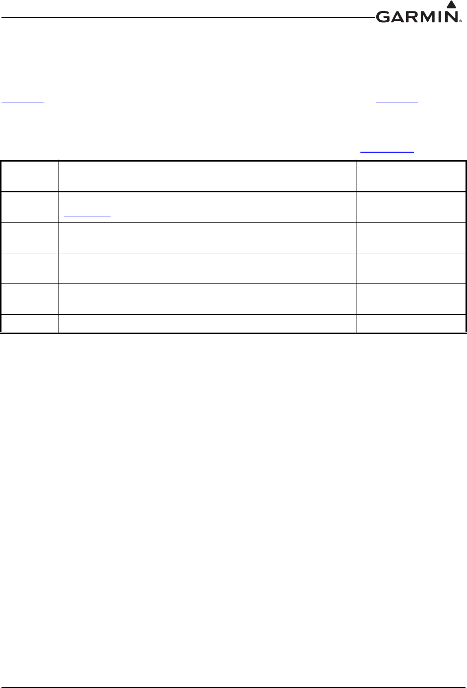
190-01553-00 GTR 200 Installation Manual
Rev. G Page A-1
APPENDIX A SHIELD BLOCK CONNECTOR INSTALLATION
INSTRUCTIONS
A.1 Shield Block Installation Parts
Table 2-3 and Table A-1 list the parts needed to install a Shield Block. Parts listed in Table 2-3 are
supplied in the GTR 200 Connector Kit (011-003240-00). Parts listed in Table A-1 are to be provided by
the installer.
Table A-1 Parts not supplied for a Shield Block Installation (Figure A-1)
Figure
Ref Description GPN or MIL spec
4Multiple Conductor Shielded Cable (2-conductor shown in
Figure A-1)
Parts used depend on
method chosen
5Drain Wire Shield Termination (method optional) Parts used depend on
method chosen
6Braid, Flat (19-20 AWG equivalent, tinned plated copper strands
36 AWG, Circular Mil Area 1000 -1300)
Parts used depend on
method chosen
7Floating Shield Termination (method optional) Parts used depend on
method chosen
13 Silicon Fusion Tape -
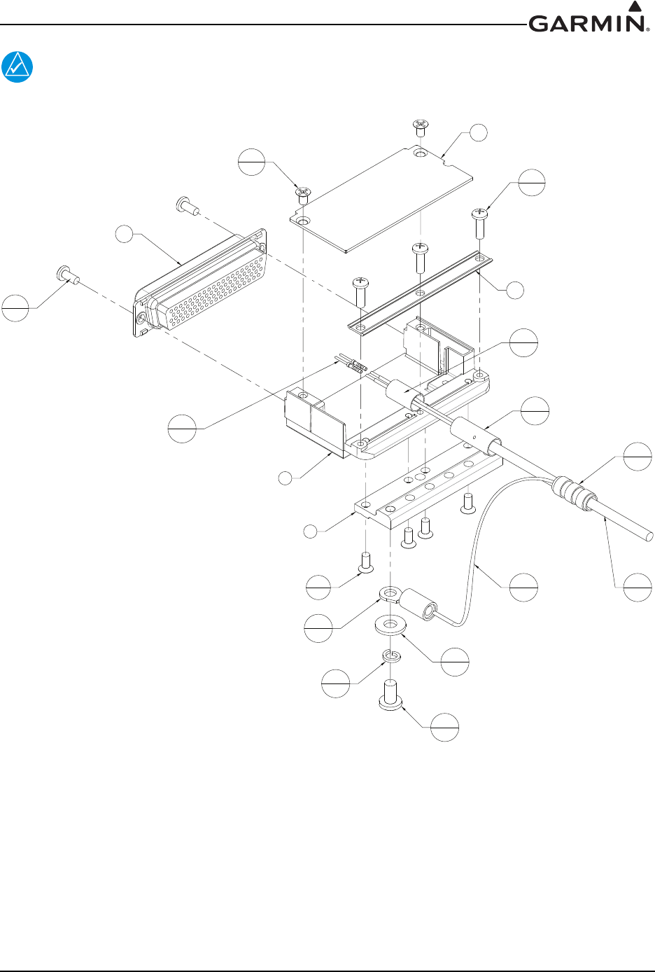
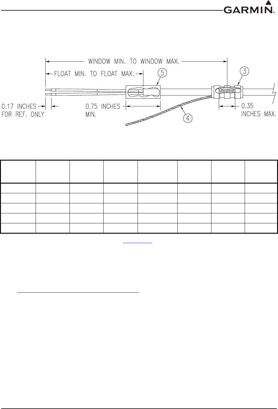
190-01553-00 GTR 200 Installation Manual
Rev. G Page A-3
A.2 Shield Termination Technique – Method A.1 (Standard)
1. The appropriate number of Shield Block Backshells will be included in the particular LRU
connector kit.
Figure A-2 Method A.1 for Shield Termination
2. At one end of a shielded cable (item 4, Figure A-1) measure a distance between “Window Min” to
“Window Max” (Table A-2) and cut a window (max size 0.35”) in the jacket to expose the shield
(item 3, Figure A-2). Use caution when cutting the jacket to avoid damaging the individual braids
of the shield. When dealing with a densely populated connector with many cables, it may prove
beneficial to stagger the windows throughout the “Window Min” to “Window Max” range. If
staggering is not needed the “Ideal Window” length is recommended.
Suggested tools to accomplish the window cut:
• Coaxial Cable Stripper
• Thermal Stripper
• Sharp Razor Blade
Table A-2 Shielded Cable Preparations for Garmin Connectors
Backshell
Size
Number of
Pins Std/
HD
Float Min
(inches)
Float Max
(inches)
Ideal Float
(inches)
Window
Min
(inches)
Window
Max
(inches)
Ideal
Window
(inches)
19/15 1.25 2.25 1.75 2.75 5.25 4.25
215/26 1.5 2.5 2.0 3.0 5.5 4.5
325/44 1.5 2.5 2.0 3.0 5.5 4.5
437/62 1.5 2.5 2.0 3.0 5.5 4.5
550/78 1.5 2.5 2.0 3.0 5.5 4.5

190-01553-00 GTR 200 Installation Manual
Rev. G Page A-4
3. Connect a Flat Braid (item 4, Figure A-2) to the shield exposed through the window of the
prepared cable assembly from step 2. The Flat Braid should go out the front of the termination
towards the connector. It is not permitted to exit the rear of the termination and loop back towards
the connector (see Figure A-2). Make this connection using an approved shield termination
technique.
NOTE
FAA AC 43.13-1B Chapter 11, Section 8 (Wiring Installation Inspection Requirements)
may be a helpful reference for termination techniques.
Preferred Method:
Slide a solder sleeve (item 3, Figure A-2) onto the prepared cable assembly and connect the Flat
Braid (item 4, Figure A-2) to the shield using a heat gun approved for use with solder sleeves. It
may prove beneficial to use a solder sleeve with a pre-installed Flat Braid versus having to cut a
length of Flat Braid to be used. The chosen size of solder sleeve must accommodate both the
number of conductors present in the cable and the Flat Braid (item 4, Figure A-2) to be attached.
Solder Sleeves with pre-installed Flat Braid
A preferred solder sleeve would be the Raychem S03 Series with the thermochromic
temperature indicator (S03-02-R-9035-100, S03-03-R-9035-100, S03-04-R-9035-100). These
solder sleeves come with a pre-installed braid and effectively take the place of items 3 and 4
shown in Figure A-2. For detailed instructions on product use, reference Raychem installation
procedure RCPS 100-70.
Raychem recommended heating tools:
• HL1802E
• AA-400 Super Heater
• CV-1981
•MiniRay
• IR-1759
Individual solder sleeves and Flat Braid
Solder Sleeves:
Reference the following MIL-Specs for solder sleeves.
(M83519/1-1, M83519/1-2, M83519/1-3, M83519/1-4, M83519/1-5)
Flat Braid:
If the preferred Raychem sleeves are not being used, the individual flat braid selected should
conform to ASTMB33 for tinned copper and be made up of 36 AWG strands to form an
approximately 19-20 AWG equivalent flat braid. A circular mil area range of 1000 to 1300 is
required. The number of individual strands in each braid bundle is not specified. (e.g.
QQB575F36T062)
NOTE
Flat Braid as opposed to insulated wire is specified in order to allow continuing air
worthiness by allowing for visual inspection of the conductor.
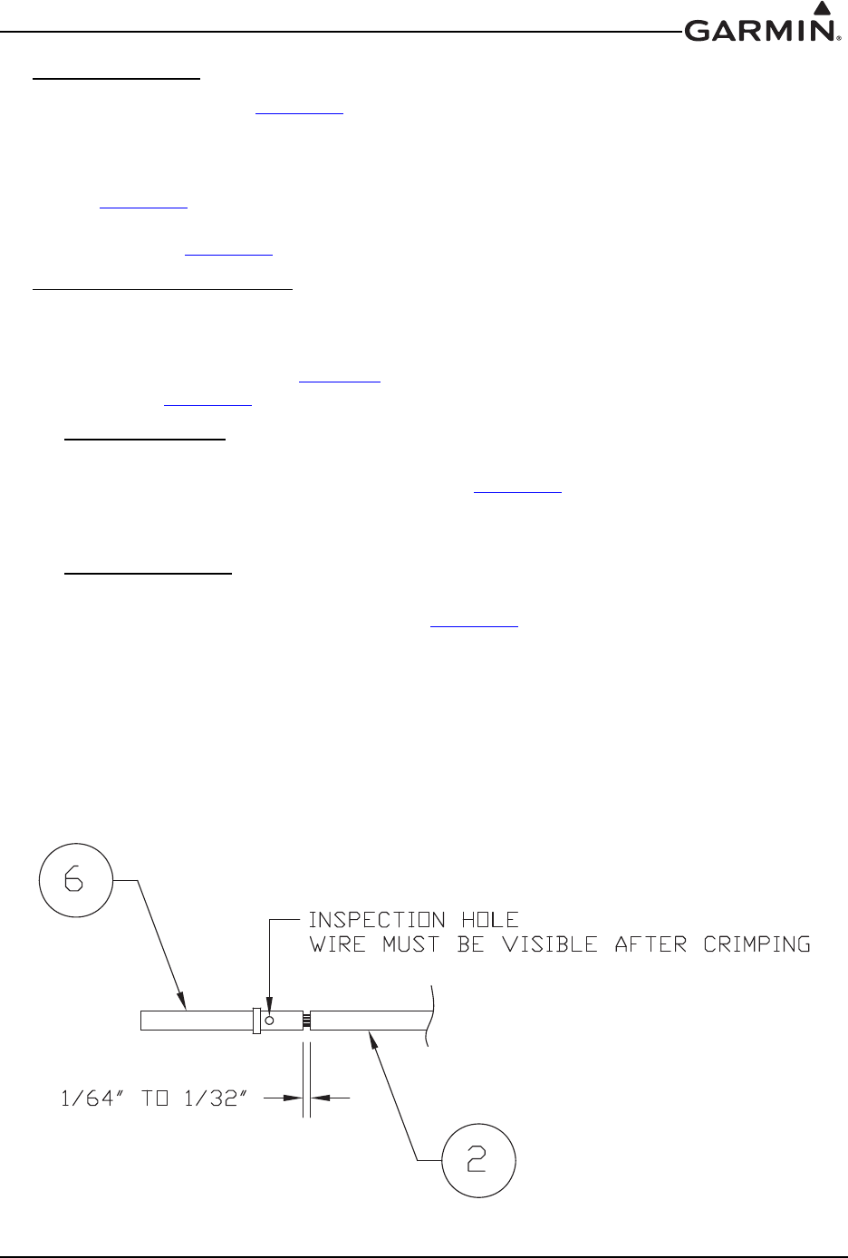
190-01553-00 GTR 200 Installation Manual
Rev. G Page A-5
Secondary Method:
Solder a Flat Braid (item 4, Figure A-2) to the shield exposed through the window of the prepared
cable assembly. Ensure a solid electrical connection through the use of acceptable soldering practices.
Use care to avoid applying excessive heat that burns through the insulation of the center conductors
and shorts the shield to the signal wire. Slide a minimum 0.75 inches of Teflon heat shrinkable tubing
(item 3, Figure A-2) onto the prepared wire assembly and shrink using a heat gun. The chosen size of
heat shrinkage tubing must accommodate both the number of conductors present in the cable and the
Flat Braid (item 4, Figure A-2) to be attached.
Teflon Heat Shrinkable Tubing:
Reference the following MIL-Spec for Teflon heat shrinkable tubing (M23053/5-X-Y).
4. At the same end of the shielded cable and ahead of the previous shield termination, strip back
“Float Min” to “Float Max” (Table A-2) length of jacket and shield to expose the insulated center
conductors (Figure A-2). The “Ideal Float” length may be best to build optimally.
Preferred Method:
The jacket and shield should be cut off at the same point so no shield is exposed. Slide 0.75 inches
minimum of Teflon heat shrinkable tubing (item 5, Figure A-2) onto the cable and use a heat gun
to shrink the tubing. The chosen size of heat shrinkage tubing must accommodate the number of
conductors present in the cable.
Secondary Method:
Leave a max 0.35 inches of shield extending past the jacket. Fold this 0.35 inches of shield back
over the jacket. Slide a solder sleeve (item 5, Figure A-2) over the end of the cable and use a heat
gun approved for solder sleeves to secure the connection. The chosen size of solder sleeve must
accommodate the number of conductors present in the cable.
5. Strip back approximately 0.17 inches of insulation from each wire of the shielded cable (item 2,
Figure A-3) and crimp a contact (item 6, Figure A-3) to each conductor. It is the responsibility of
the installer to determine the proper length of insulation to be removed. Wire must be visible in
the inspection hole after crimping and the insulation must be 1/64 – 1/32 inches from the end of
the contact as shown in Figure A-3.
Figure A-3 Insulation/Contact Clearance

190-01553-00 GTR 200 Installation Manual
Rev. G Page A-6
NOTE
Refer to Figure A-1 for all item numbers in the following steps 6-13.
6. Insert newly crimped pins and wires into the appropriate connector housing location as specified
by the installation wiring diagrams.
7. Cut the Flat Braid (item 6) to a length that, with the addition of a ring terminal, will reach one of
the tapped holes of the Shield Block backshell (item 1). An appropriate amount of excess length
without looping should be given to the Flat Braid (item 6) to allow it to freely move with the wire
bundle.
NOTE
Position the window splice to accommodate a Flat Braid (item 6) length of no more than 4
inches.
8. Guidelines for terminating the newly cutoff Flat Braid(s) (item 6) with insulated ring terminals
(item 9):
• Each tapped hole on the Ring Terminal Adapter (item 2) may accommodate only two ring
terminals (item 9).
• It is preferred that only two Flat Braid(s) (item 6) be terminated per ring terminal. Two Flat
Braids per ring terminal will necessitate the use of a Ring terminal, #8, insulated, 14-16
AWG (MS25036-153).
• If only a single Flat Braid is left or if only a single Flat Braid is needed for this connector a
Ring terminal, #8, insulated, 18-22 AWG (MS25036-149) can accommodate this single Flat
Braid.
• If more braids exist for this connector than two per ring terminal, it is permissible to
terminate three braids per ring terminal. This will necessitate the use of a Ring terminal, #8,
insulated, 10-12 AWG (MS25036-156).
9. Repeat steps 2 through 8 as needed for the remaining shielded cables.
10. Terminate the ring terminals to the Ring Terminal Adapter (item 2) by placing items on the Pan
Head Screw (item 10) in the following order: Split Washer (item 11), Flat Washer (item 12) first
Ring Terminal, second Ring Terminal (if needed) before finally inserting the screw into the tapped
holes on the Ring Terminal Adapter. Do not violate the guidelines presented in Step 8 regarding
ring terminals.
11. It is recommended to wrap the cable bundle with Silicone Fusion Tape (item 13)
(GPN: 249-00114-00 or a similar version) at the point where the backshell clamp and cast housing
will contact the cable bundle.
NOTE
Choosing to use this tape is the discretion of the installer.
12. Place the smooth side of the backshell clamp (item 14) across the cable bundle and secure using
the three screws (item 15). Warning: Placing the grooved side of the clamp across the cable bundle
may risk damage to wires.
13. Attach the cover (item 16) to the backshell (item 1) using the two screws (item 17).
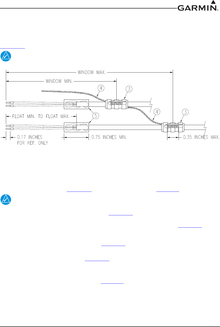
190-01553-00 GTR 200 Installation Manual
Rev. G Page A-7
A.3 Shield Termination Technique - Method A.2 (Daisy Chain)
In rare situations where more braids need to be terminated for a connector than three per ring terminal it is
allowable to daisy chain a maximum of two shields together (see Figure A-4) before coming to the ring
terminal. All other restrictions and instructions for the shield termination technique set forth for
Method A.1 are still applicable.
NOTE
The maximum length of the combined braids should be approximately 4 inches.
Figure A-4 Method A.2 (Daisy Chain) for Shield Termination
A.4 Shield Termination – Method B.1 (Quick Term)
If desired, the drain wire termination (item 3, Figure A-4) and the floating shield termination (item 5,
Figure A-4) can be effectively combined into a “Quick Term”. This method eliminates the float in the
cable insulation and moves the placement of the window which was described by the dimensions “Window
Min” and “Window Max” from Method A.1. This technique is depicted in Figure A-5.
NOTE
The original purpose for separating the shield drain termination (item 3, Figure A-4) from
the float termination (item 5, Figure A-4) in Method A.1 was to allow for a variety of
lengths for the drain wires so that the shield drain terminations (item 3, Figure A-4) would
not all “bunch up” in the harness and to eliminate loops in the drain wires. If Method B.1
is chosen, as described in this section, care must be taken to ensure that all drain shield
terminations can still be inspected. With connectors which require a large number of
shield terminations it may be best to use Method A.1. This will allow the drain shield
terminations (item 3, Figure A-4) a larger area to be dispersed across.
Using this method, the instructions from Section A.2 (Method A) are followed except that:
1. Step 2 is eliminated
2. Steps 3 and 4 are replaced by the following:
At the end of the shielded cable (item 4, Figure A-1), strip “Quick Term Min” to “Quick Term
Max” (Table A-3) length of the jacket to expose the shield. Next trim the shield so that at most
0.35 inches remains extending beyond the insulating jacket. Fold this remaining shield back over
the jacket.
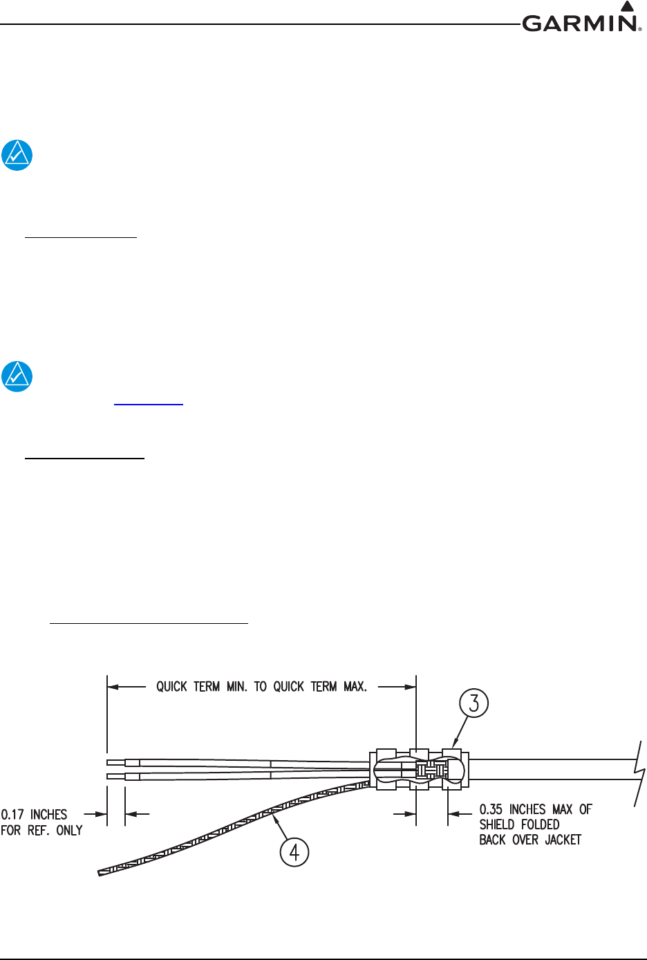
190-01553-00 GTR 200 Installation Manual
Rev. G Page A-8
Connect a Flat Braid (item 4, Figure A-5) to the folded back shield of the prepared cable assembly.
The flat braid should go out the front of the termination towards the connector. It is not permitted
to exit the rear of the termination and loop back towards the connector (Figure A-5). Make this
connection using an approved shield termination technique.
NOTE
FAA AC 43.13-1B Chapter 11, Section 8 (Wiring Installation Inspection Requirements)
may be a helpful reference for termination techniques.
Preferred Method:
Slide a solder sleeve (item 3, Figure A-5) onto the prepared cable assembly and connect the Flat Braid
(item 4, Figure A-5) to the shield using a heat gun approved for use with solder sleeves. It may prove
beneficial to use a solder sleeve with a pre-installed Flat Braid versus having to cut a length of Flat
Braid to be used. The chosen size of solder sleeve must accommodate both the number of conductors
present in the cable and the Flat Braid (item 4, Figure A-5) to be attached.
NOTE
Reference Section A.2 for recommended solder sleeves and flat braid. The same
recommendations are applicable to this technique.
Secondary Method:
Solder a Flat Braid (item 4, Figure A-5) to the folded back shield on the prepared cable assembly.
Ensure a solid electrical connection through the use of acceptable soldering practices. Use care to
avoid applying excessive heat that burns through the insulation of the center conductors and shorts the
shield to the signal wire. Slide a minimum of 0.75 inches of Teflon heat shrinkable tubing onto the
prepared wire assembly and shrink using a heat gun. The chosen size of heat shrinkage tubing must
accommodate both the number of conductors present in the cable as well as the Flat Braid (item 4,
Figure A-5) to be attached.
Teflon Heat Shrinkable Tubing:
Reference the following MIL-Spec for general Teflon heat shrinkable tubing (M23053/5-X-Y)
Figure A-5 Method B.1 (Quick Term) for Shield Termination
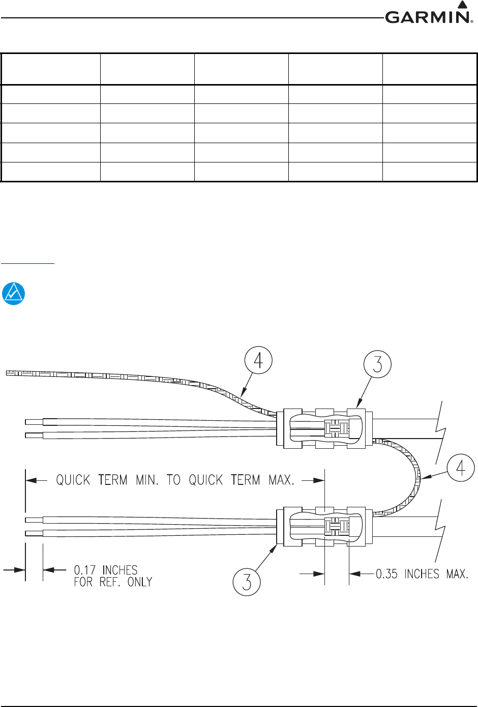
190-01553-00 GTR 200 Installation Manual
Rev. G Page A-9
A.5 Shield Termination-Method B.2 (Daisy Chain-Quick Term)
In rare situations where more braids need to be terminated for a connector than three per ring terminal it is
allowable to daisy chain a maximum of two shields together before coming to the ring terminal
(Figure A-6). All other restrictions and instructions for the shield termination technique set forth for
Method B.1 are still applicable.
NOTE
The maximum length of the combined braids should be approximately 4 inches.
Figure A-6 Method B.2 (Daisy Chain-Quick Term) for Shield Termination
Table A-3 Shielded Cable Preparations – (Quick Term)
Backshell Size Number of Pins
Std/HD
Quick Term Min
(inches)
Quick Term Max
(inches)
Quick Term
Float (inches)
19/15 1.25 2.25 1.75
215/26 1.5 2.5 2.0
325/44 1.5 2.5 2.0
437/62 1.5 2.5 2.0
550/78 1.5 2.5 2.0
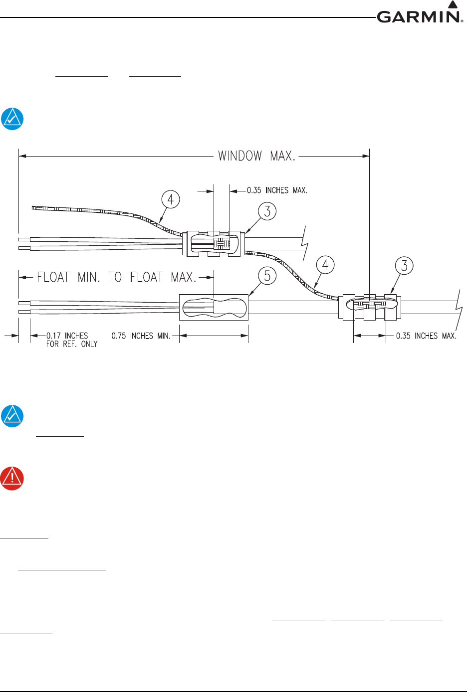
190-01553-00 GTR 200 Installation Manual
Rev. G Page A-10
A.6 Daisy Chain between Methods A and B
In rare situations where more braids need to be terminated for a connector than three per ring terminal and
a mixture of Method A.1 and Method B.1 have been used, it is allowable to daisy chain a maximum of two
shields together from a Method A termination to a Method B (Figure A-7). All other restrictions and
instructions for the shield termination technique set forth for Method A and B are still applicable.
NOTE
The maximum length of the combined braids should be approximately 4 inches.
Figure A-7 Daisy Chain between Methods A and B
A.7 Splicing Signal Wires
NOTE
Figure A-8 illustrates that a splice must be made within a 3 inch window from outside the
edge of clamp to the end of the 3 inch max mark.
WARNING
Keep the splice out of the backshell for pin extraction, and outside of the strain relief to
avoid preloading.
Figure A-8 shows a two wire splice, but a maximum of three wires can be spliced. If a third wire is
spliced, it is located out front of splice along with signal wire going to pin.
Splice part numbers:
• Raychem D-436-36/37/38
• MIL Spec MIL-S-81824/1
This technique may be used with shield termination methods: Method A.1, Method A.2, Method B.1, and
Method B.2.
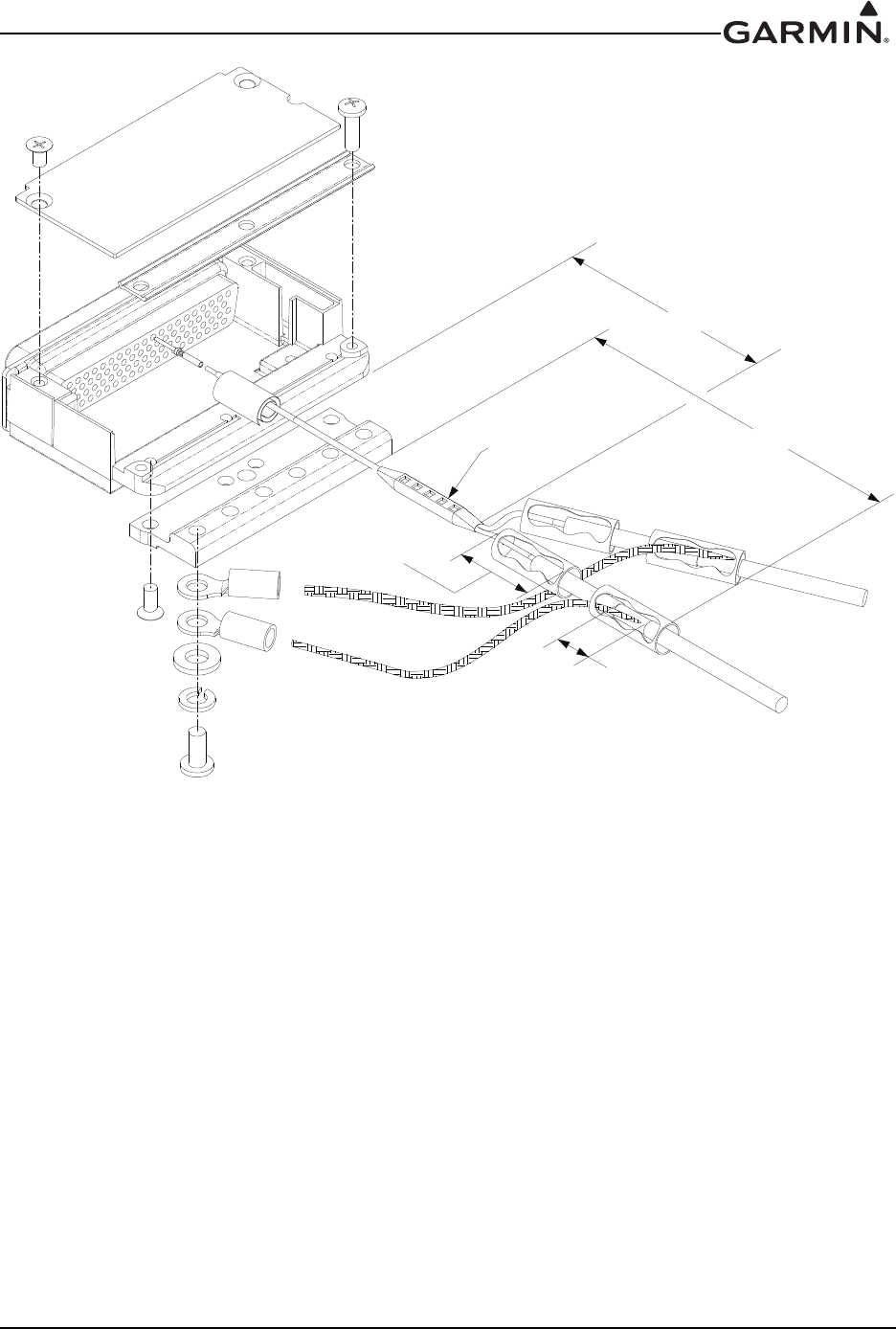
190-01553-00 GTR 200 Installation Manual
Rev. G Page A-11
Figure A-8 D-Sub Spliced Signal Wire illustration
0.75 inches MIN.
SHRINKABLE
TUBING
END OF SHIELD BLOCK
4 inches MAX.
0.35 inches MAX.
WINDOW SIZE
SLEEVE EDGE
EDGE OF STRAIN RELIEF
OUTER EDGE OF SPLICE
3 inches MAX.
SPLICE
OUTER SOLDER

190-01553-00 GTR 200 Installation Manual
Rev. G Page B-1
APPENDIX B SERIAL INTERFACE SPECIFICATIONS
B.1 Electrical Interface
The I/O signals are compatible with RS-232. Data is generated at 9600 baud with a word length of 8 bits,
one stop bit, and no parity.
The data format for the serial communication is:
Baud rate 9600
Data bits 8
Stop bits 1
Parity None
B.2 Message Formats
All messages conform to the NMEA 0183 proprietary message format as follows. All characters will be
standard ASCII characters. No binary data characters are used.
“$”....................Start of message character, ASCII “$” (024h).
“P” ...................Proprietary message identifier.
iii......................Company identifier.
c .......................Message class identifier; Identifies a message as either a COMM or NAV
message.
nn .....................Message identifier, two-digit number in ASCII characters.
d.....d ................Message data characters defined for each message.
Chksum............Message checksum, including message identifier (nn) through data characters
(d…..d). The two-digit checksum is generated by adding all values of valid
characters together, ignoring carry (if any). This value is converted into two
encoded hex1 characters (30h-3Fh).
<CR> ...............ASCII carriage return (0Dh).
<LF> ................ASCII line feed (0Ah).
1Encoded hex: each character consists of 4 bits of data placed in the low order nibble +30h. For example,
the 8-bit value 5Fh would be encoded as two characters with values of 35h and 3Fh, which map to the
ASCII characters “5” and “?”, respectively.
The maximum message length, including the start of message character (“$”) and the end of message
<CR><LF> sequence, is 29 bytes.

190-01553-00 GTR 200 Installation Manual
Rev. G Page B-2
B.2.1 Message Definitions
B.2.1.1 Frequency Types
B.2.1.1.1 Enhanced Frequency Type Enumeration
0Tower
1Ground
2 Automatic Terminal Information Service or ATIS
3 Air Traffic Frequency
4 Approach
5 Arrival
6 Automatic Weather Observing Station
7 Clearance/Delivery
8 Common Traffic Advisory Frequency
9 Departure
: Flight Service Station
; Remote Flight Service Station
<Unicom
= Mandatory Frequency
> No type specified
?Undefined
@Center
A Automated Surface Observing Station
B Class B
C Class C
DRadio
EEnroute
F Enroute Flight Advisory Service or Flight Watch
GGate
H Helicopter
I Information
J Weather
KTerminal
L Pilot controlled lighting
M Multicom
N Radar
O Operations
PRamp
Q Reserved - Undefined

190-01553-00 GTR 200 Installation Manual
Rev. G Page B-3
B.2.1.1.2 Legacy Frequency Type Enumeration
0Tower
1Ground
2 Automatic Terminal Information Service or ATIS
3 Air Traffic Frequency
4 Approach
5 Arrival
6 Automatic Weather Observing Station
7 Clearance/Delivery
8 Common Traffic Advisory Frequency
9 Departure
: Flight Service Station
; Remote Flight Service Station
<Unicom
= Mandatory Frequency
> No type specified
?Undefined
B.2.2 Input Messages
B.2.2.1 Set Active Frequency and Transceiver Function
This message is used to set the Active frequency as well as the transceiver function.
Message format (GTR 200):
“GRM”.............Company identifier.
“C” ...................Message class.
“15”..................Message identifier.
mk ....................Active frequency: m = MHz, where m = desired MHz frequency - 30h, ranging
from 118 to 136 MHz, (i.e. 76h to 88h, A2h); k = (KHz offset / 25KHz) + 30h,
ranging from 000 to 975KHz in 25 KHz steps.
a .......................Transceiver function: N = normal, M = monitor, 0 = unchanged.
“0”....................8.33 KHz offset: (ASCII) 0 = 25 KHz frequency (.000)
iiii.....................Identifier string. Note that if the identifier string is less than four characters, left
justify the string and insert spaces for empty characters. An empty identifier
string (four spaces) is allowed. Identifiers are restricted to using ASCII characters
0-9 and A-Z.
f........................Frequency type (see Extended Frequency Type Enumeration).
Example message:
$PGRMC15W=N0KIXDA<chksm><CR><LF>
This example command would set the active COM frequency to 135.325 MHz with an identifier of “KIXD
ASOS”, and place the radio in Normal receive mode. This is interpreted by noting that the ASCII ‘W’
corresponds with 57h, +30h = 87h, converted to decimal equals 135 for the MHz portion. The KHz
portion converts ASCII ‘=’ to 3Dh, -30h yields Dh, x25KHz steps = 325 KHz, with no 8.33 KHz channel
offsets. The identifier string portion is “KIXD” and the frequency type ‘A’ corresponds to “Automated
Surface Observing Station” in the extended frequency type enumeration.

190-01553-00 GTR 200 Installation Manual
Rev. G Page B-4
Message format (GTR 225/GNC 255):
“GRM”.............Company identifier.
“C” ...................Message class.
“00”..................Message identifier.
mk ....................Active frequency: m = MHz, where m = desired MHz frequency - 30h, ranging
from 118 to 136 MHz, (i.e. 76h to 88h, A2h); k = (KHz offset / 25KHz) + 30h,
ranging from 000 to 975KHz in 25 KHz steps.
a .......................Transceiver function: N = normal, M = monitor, 0 = unchanged.
“0”....................8.33 KHz offset: (ASCII) 0 = 25 KHz frequency (.000)
Example message:
$PGRMC00G4N0<chksm><CR><LF>
This example command would set the active COM frequency to 119.100 MHz and place the radio in
Normal receive mode. This is interpreted by noting that the ASCII ‘G’ corresponds with 47h, +30h = 77h,
converted to decimal equals 119 for the MHz portion. The KHz portion converts ASCII ‘4’ to 34h, -30h
yields 4h, x25KHz steps = 100 KHz, with no 8.33 KHz channel offset.
Message format (SL 30):
“MRR”.............Company identifier.
“V”...................Message class.
“42”..................Message identifier.
mk ....................Active frequency: m = MHz, where m = desired MHz frequency - 30h, ranging
from 118 to 136 MHz, (i.e. 76h to 88h, A2h); k = (KHz offset / 25KHz) + 30h,
ranging from 000 to 975KHz in 25 KHz steps.
a .......................Transceiver function: N = normal, M = monitor, 0 = unchanged.
Example message:
$PMRRV42G4N<chksm><CR><LF>
Sets the active frequency to 119.100MHz, normal receive mode. “G” = 119d - 30h = 77h - 30h = 47h, or
an ASCII “G”; “4” = 100 kHz/25 kHz + 30h = 4 + 30h = 34h, or an ASCII “4.”
Message format (SL 40):
“GRM”.............Company identifier.
“C” ...................Message class.
“00”..................Message identifier.
mk ....................Active frequency: m = MHz, where m = desired MHz frequency - 30h, ranging
from 118 to 136 MHz, (i.e. 76h to 88h, A2h); k = (KHz offset / 25KHz) + 30h,
ranging from 000 to 975KHz in 25 KHz steps.
a .......................Transceiver function: N = normal, M = monitor, 0 = unchanged.
Example message:
$PMRRC00G4N<chksm><CR><LF>
Sets the active frequency to 119.100MHz, normal receive mode. “G” = 119d - 30h = 77h - 30h = 47h, or
an ASCII “G”; “4” = 100 kHz/25 kHz + 30h = 4 + 30h = 34h, or an ASCII “4.”
NOTE
Input frequencies will be checked for validity. An RS-232 serial error message output will
be generated if the frequency is invalid, or an 8.33 KHz frequency is requested.

190-01553-00 GTR 200 Installation Manual
Rev. G Page B-5
NOTE
The GTR will ignore this message while transmitting on the active COM frequency.
B.2.2.2 Set Standby Frequency and Transceiver Function
This message is used to set the Standby frequency as well as the transceiver function.
Message format (GTR 200):
“GRM”.............Company identifier.
“C” ...................Message class.
“16”..................Message identifier.
mk ....................Standby frequency: m = MHz, where m = desired MHz frequency - 30h, ranging
from 118 to 136 MHz, (i.e. 76h to 88h, A2h); k = (KHz offset / 25KHz) + 30h,
ranging from 000 to 975KHz in 25 KHz steps.
a .......................Transceiver function: N = normal, M = monitor, 0 = unchanged.
“0”....................8.33 KHz offset: (ASCII) 0 = 25 KHz frequency (.000)
iiii.....................Identifier string. Note that if the identifier string is less than four characters, left
justify the string and insert spaces for empty characters. An empty identifier
string (four spaces) is allowed. Identifiers are restricted to using ASCII characters
0-9 and A-Z.
f........................Frequency type (see Extended Frequency Type Enumeration).
Example message:
$PGRMC16G>M0KOJC2<chksm><CR><LF>
This example command would set the standby frequency to 119.350 MHz with an identifier of “KOJC
ATIS”, and place the radio in Monitor mode. This is interpreted by noting that the ASCII ‘G’ corresponds
with 47h, +30h = 77h, converted to decimal equals 119 for the MHz portion. The KHz portion converts
ASCII ‘>’ to 3Eh, -30h yields Eh, x25KHz steps = 350 KHz, with no 8.33 KHz channel offset. The
identifier string portion is “KOJC” and the frequency type ‘2’ corresponds to “Automated Terminal
Information Station” in the extended frequency type enumeration.
Message format (GTR 225/GNC 255):
“GRM”.............Company identifier.
“C” ...................Message class.
“01”..................Message identifier.
mk ....................Standby frequency: m = MHz, where m = desired MHz frequency - 30h, ranging
from 118 to 136 MHz, (i.e. 76h to 88h, A2h); k = (KHz offset / 25KHz) + 30h,
ranging from 000 to 975KHz in 25 KHz steps.
a .......................Transceiver function: N = normal, M = monitor, 0 = unchanged.
“0”....................8.33 KHz offset: (ASCII) 0 = 25 KHz frequency (.000)
Example message:
$PGRMC01KFM0<chksm><CR><LF>
This example command would set the standby frequency to 123.550MHz and place the radio in Monitor
mode. This is interpreted by noting that the ASCII ‘K’ corresponds with 4Bh, +30h = 7Bh, converted to
decimal equals 123 for the MHz portion. The KHz portion converts ASCII ‘F’ to 46h, -30h yields 16h,
x25KHz steps = 550KHz , with no 8.33 KHz channel offset.

190-01553-00 GTR 200 Installation Manual
Rev. G Page B-6
Message format (SL30):
“MRR”.............Company identifier.
“V”...................Message class.
“29”..................Message identifier.
mk ....................Standby frequency: m = MHz, where m = desired MHz frequency - 30h, ranging
from 118 to 136 MHz, (i.e. 76h to 88h, A2h); k = (KHz offset / 25KHz) + 30h,
ranging from 000 to 975KHz in 25 KHz steps.
a .......................Transceiver function: N = normal, M = monitor, 0 = unchanged.
Example message:
$PMRRV29G4N<chksm><CR><LF>
Sets the standby frequency to 119.100MHz, normal receive mode. “G” = 119d - 30h = 77h - 30h = 47h, or
an ASCII “G”; “4” = 100 kHz/25 kHz + 30h = 4 + 30h = 34h, or an ASCII “4.”
Message format (SL 40):
“MRR”.............Company identifier.
“C” ...................Message class.
“01”..................Message identifier.
mk ....................Standby frequency: m = MHz, where m = desired MHz frequency - 30h, ranging
from 118 to 136 MHz, (i.e. 76h to 88h, A2h); k = (KHz offset / 25KHz) + 30h,
ranging from 000 to 975KHz in 25 KHz steps.
a .......................Transceiver function: N = normal, M = monitor, 0 = unchanged.
Example message:
$PMRRC01G4N<chksm><CR><LF>
Sets the standby frequency to 119.100MHz, normal receive mode. “G” = 119d - 30h = 77h - 30h = 47h, or
an ASCII “G”; “4” = 100 kHz/25 kHz + 30h = 4 + 30h = 34h, or an ASCII “4.”
NOTE
Input frequencies will be checked for validity. An RS-232 serial error message output will
be generated if the frequency is invalid, or an 8.33 KHz frequency is requested.

190-01553-00 GTR 200 Installation Manual
Rev. G Page B-7
B.2.2.3 Select Squelch Override
This message is used to turn the receiver manual squelch override on and off.
Message format:
“GRM”.............Company identifier.
“C” ...................Message class.
“03”..................Message identifier.
n .......................Squelch override: (ASCII) 0 = off; 1 = on
Example message:
$PGRMC030<chksm><CR><LF>
Set the squelch to normal operation.
B.2.2.4 Remote Frequency Lists
The following two messages work together in allowing remotely connected devices to provide frequency
lists associated with and airport. The host device should first send the Remote Airport Identifier Name
message, followed by a sequence of Remote Frequency Input messages. The list type field is used to tie the
two messages together. Up to ten frequency lists are supported, each containing up to twenty entries.
B.2.2.4.1 Remote Airport Identifier Name
This message provides the airport identifier name that is used to identify to the user which airport facility
that the list of frequencies is associated with.
Message format (GTR 200):
“GRM”.............Company identifier.
“C” ...................Message class.
“04”..................Message identifier.
t ........................List type: (ASCII) “0”, “1”,…, “9”
aaaa ..................Airport Identifier of the frequency list. Note that if the airport is three characters,
then the fourth character will be filled with a space. Airport Identifiers are
restricted to using ASCII characters 0-9 and A-Z.
Example message:
$PGRMC041KOJC<chksm><CR><LF>
Airport Identifier to be associated with list #1, Airport Identifier to display is “KOJC”.
Message format (SL 40):
“MRR”.............Company identifier.
“C” ...................Message class.
“04”..................Message identifier.
t ........................List type: (ASCII) “0”, “1”,…, “9”.
aaaa ..................Airport Identifier of the frequency list. Note that if the airport is three characters,
then the fourth character will be filled with a space. Airport Identifiers are
restricted to using ASCII characters 0-9 and A-Z.
Example message:
$PMRRC042K81<space><chksm><CR><LF>
Airport Identifier to be associated with list #2, Airport Identifier to display is “K81 ”.

190-01553-00 GTR 200 Installation Manual
Rev. G Page B-8
B.2.2.4.2 Remote Airport Frequency Input
This message is used to input frequency data for the specified list type.
Message format (GTR 200):
“GRM”.............Company identifier.
“C” ...................Message class.
“05”..................Message identifier.
t ........................List type: (ASCII) “0”, “1”,…, “9”.
f........................Frequency type (see Extended Frequency Type Enumeration).
mk ....................Frequency: m = MHz, where m = desired MHz frequency - 30h, ranging from 118
to 136 MHz, (i.e. 76h to 88h, A2h); k = (KHz offset / 25KHz) + 30h, ranging from
000 to 975KHz in 25 KHz steps.
“0”....................8.33 KHz offset: (ASCII) 0 = 25 KHz frequency (.000)
Example message:
$PGRMC051AG>0<chksm><CR><LF>
Airport frequency list “1”, automated surface observing station type, 119.250 MHz.
Message format (SL 40):
“MRR”.............Company identifier.
“C” ...................Message class.
“05”..................Message identifier.
t ........................List type: (ASCII) “0”, “1”,…, “9”.
f........................Frequency type (see Legacy Frequency Type Enumeration).
mk ....................Frequency: m = MHz, where m = desired MHz frequency - 30h, ranging from 118
to 136 MHz, (i.e. 76h to 88h, A2h); k = (KHz offset / 25KHz) + 30h, ranging from
000 to 975KHz in 25 KHz steps.
Example message:
$PMRRC052<JP<chksm><CR><LF>
Airport frequency list “2”, unicom type, 122.800 MHz.

190-01553-00 GTR 200 Installation Manual
Rev. G Page B-9
B.2.2.5 Remote Frequency Identifier Lookup Table
The following two messages work together in allowing remotely connected devices to provide frequency
identifier lookup information. The host device will send a Set Remote Frequency Table Entry message to
add entries to the table, and Delete Remote Frequency Table Entries message to remove entries from the
table. The table should be presorted by the host in order of frequency and not have any empty entries
between the first and last entry (empty entries at the end are ok). When manually tuning a frequency the
table will be checked for a matching frequency, and if found the frequency identifier for the entry will be
used. The table can hold at most 255 entries.
B.2.2.5.1 Set Remote Frequency Table Entry
This message is used to add entries to the remote frequency lookup table.
Message format:
“GRM”.............Company identifier.
“C” ...................Message class.
“17”..................Message identifier.
nnn ...................List index (0-254)
mk ....................Frequency: m = MHz, where m = desired MHz frequency - 30h, ranging from 118
to 136 MHz, (i.e. 76h to 88h, A2h); k = (KHz offset / 25KHz) + 30h, ranging from
000 to 975KHz in 25 KHz steps.
“0”....................8.33 KHz offset: (ASCII) 0 = 25 KHz frequency (.000)
iiii.....................Identifier string. Note that if the identifier string is less than four characters, left
justify the string and insert spaces for empty characters. An empty identifier string
(four spaces) is allowed. Identifiers are restricted to using ASCII characters 0-9
and A-Z.
f........................Frequency type (see Extended Frequency Type Enumeration).
Example message:
$PGRMC17025G>0KOJCA<chksm><CR><LF>
Add entry 119.250 MHz frequency, KOJC identifier, automated surface observing station type, at table
index 25.
B.2.2.5.2 Delete Remote Frequency Table Entries
This message is used to delete entries from the end of the remote frequency lookup table.
Message format:
“GRM”.............Company identifier.
“C” ...................Message class.
“18”..................Message identifier.
nnn ...................Starting list index (0-254)
sss.....................Number of entries to delete, set to “255”. As implemented this parameter is not
used. All entries between nnn and the end of the table are deleted.
Example message:
$PGRMC18200255<chksm><CR><LF>
Delete frequency lookup table entries starting from index 200 to the end of the table.

190-01553-00 GTR 200 Installation Manual
Rev. G Page B-10
B.2.2.6 Request Output Data
This message is used to request an output message be sent.
Message format:
“MRR”.............Company identifier.
“C” ...................Message class.
“06”..................Message identifier.
ii.......................Output identifier of requested message: “03” = software version message.
dd .....................Message data, set to “00”.
a .......................Request type, set to “0”.
Example message:
$PMRRC0603000<chksm><CR><LF>
Request software version message be sent.
B.2.3 Output Messages
B.2.3.1 Transceiver Status
This message is used to output the current status of the transceiver. This message is sent at a 1Hz rate or
whenever the transceiver status changes.
Message format (GTR 200/GTR 225/GNC 255):
“GRM”.............Company identifier.
“C” ...................Message class.
“01”..................Message identifier.
mk ....................Active frequency: m = MHz, where m = desired MHz frequency - 30h, ranging
from 118 to 136 MHz, (i.e. 76h to 88h, A2h); k = (KHz offset / 25KHz) + 30h,
ranging from 000 to 975KHz in 25 KHz steps.
mk ....................Standby frequency: m = MHz, where m = desired MHz frequency - 30h, ranging
from 118 to 136 MHz, (i.e. 76h to 88h, A2h); k = (KHz offset / 25KHz) + 30h,
ranging from 000 to 975KHz in 25 KHz steps.
a .......................Transceiver status:
I = Intercom (no other status applicable)
R = Normal receive
M = Monitor selected
T = Transmit enable
S = Stuck mic
F = Comm failure
s........................Squelch setting: (ASCII) 0 = automatic; 1 = manual override
hh .....................COM channel spacing: (ASCII) 25 = 25kHz
o .......................Active frequency 8.33 KHz offset: (ASCII) 0 = 25 KHz frequency (.000)
o .......................Standby frequency 8.33 KHz offset: (ASCII) 0 = 25 KHz frequency (.000)
Example Message:
$PGRMC01G4LFR02500<chksm><CR><LF>
Active frequency is 119.100MHz, the standby frequency is 124.550MHz, unit is receiving, and squelch is
automatic.

190-01553-00 GTR 200 Installation Manual
Rev. G Page B-11
Message format (SL 40):
“MRR”.............Company identifier.
“C” ...................Message class.
“01”..................Message identifier.
mk ....................Active frequency: m = MHz, where m = desired MHz frequency - 30h, ranging
from 118 to 136 MHz, (i.e. 76h to 88h, A2h); k = (KHz offset / 25KHz) + 30h,
ranging from 000 to 975KHz in 25 KHz steps.
mk ....................Standby frequency: m = MHz, where m = desired MHz frequency - 30h, ranging
from 118 to 136 MHz, (i.e. 76h to 88h, A2h); k = (KHz offset / 25KHz) + 30h,
ranging from 000 to 975KHz in 25 KHz steps.
a .......................Transceiver status:
R = Normal receive
M = Monitor receive
T = Transmit active
S = Stuck mic
s........................Squelch test setting: (ASCII) 0 = automatic; 1 = test selected
Example message:
$PMRRC01G4LFR0<chksm><CR><LF>
Active frequency is 119.100MHz, the standby frequency is 124.550MHz, receive function, and squelch is
automatic.
Message format (SL 30):
“MRR”.............Company identifier.
“V”...................Message class.
“35”..................Message identifier.
mk ....................Active frequency: m = MHz, where m = desired MHz frequency - 30h, ranging
from 118 to 136 MHz, (i.e. 76h to 88h, A2h); k = (KHz offset / 25KHz) + 30h,
ranging from 000 to 975KHz in 25 KHz steps.
mk ....................Standby frequency: m = MHz, where m = desired MHz frequency - 30h, ranging
from 118 to 136 MHz, (i.e. 76h to 88h, A2h); k = (KHz offset / 25KHz) + 30h,
ranging from 000 to 975KHz in 25 KHz steps.
a .......................Transceiver status:
R = Normal receive
M = Monitor receive
T = Transmit active
S = Stuck mic
F = Comm failure
s........................Squelch test setting: (ASCII) 0 = automatic; 1 = test selected
Example message:
$PMRRV35G4LFR0<chksm><CR><LF>
Active frequency is 119.100MHz, the standby frequency is 124.550MHz, receive function, and squelch is
automatic.

190-01553-00 GTR 200 Installation Manual
Rev. G Page B-12
B.2.3.2 Software Version
This message is used to output the software version string.
Message format:
“MRR”.............Company identifier.
“C” ...................Message class.
“03”..................Message identifier.
vvvv .................Software version in ASCII
Example message:
$PMRRC030200<chksm><CR><LF>
Software version is 2.00.
B.2.3.3 Communications Error
This message is used to indicate a communications error. When possible, the company identifier and
message class will match the company identifier and message class of the offending message.
Message format:
iii......................Company identifier.
c .......................Message class: “05” for COMM messages; “27” for NAV messages.
nn .....................Message identifier.
e .......................Error code: (ASCII)
0 = input message checksum
1 = unknown message
2 = error or mismatch in message data
Example message:
$PGRMC051<chksm><CR><LF>
Received an unknown message using company ID “GRM” and message class “C”.
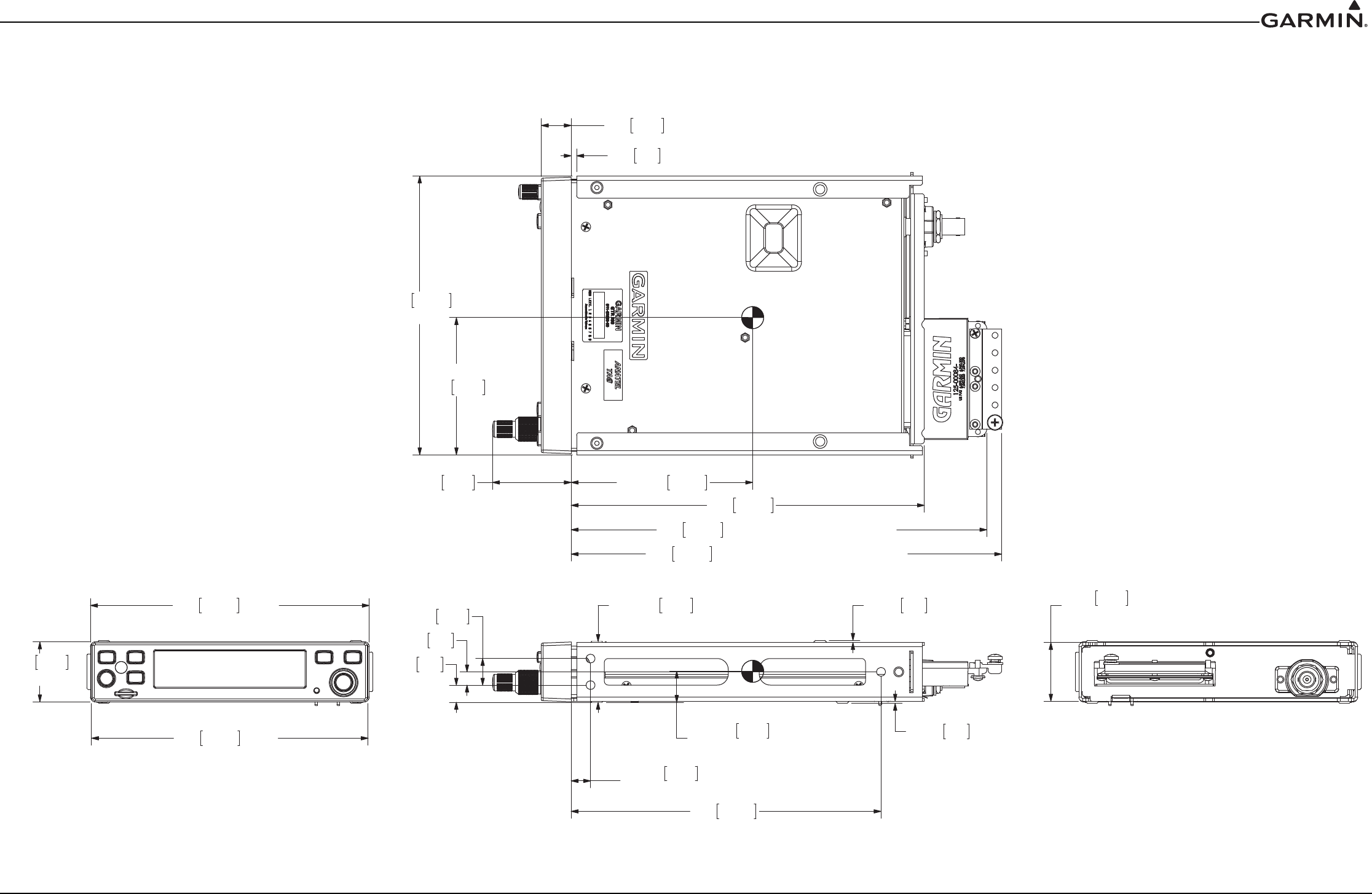
190-01553-00 GTR 200 Installation Manual
Revision G Page C-1
APPENDIX C OUTLINE AND INSTALLATION DRAWINGS
Figure C-1 GTR 200 Outline Drawing
CG .70 17.8 FROM
RACK FRONT DIMPLE
CG 4.10 104.1
CG
3.10 78.7
BEZEL
6.25 158.8
34.31.35
BEZEL
6.30 160.0 RACK
PANEL TO MOUNTING HOLES
SPACING DIMPLE
FROM FRONT OF A/C
11.1
177.87.00
9.8
.388
15.2.60
34.9 DIMPLE TO DIMPLE 2X .05 1.3 SPACING DIMPLE2X 1.375
2X .05 1.3
4X .437
.30 7.6
3.2
.125
202.7
7.98
6.30
TO CONNECTOR BACKSHELL
238.5
17.1.675
9.39
1.78 45.2
160.0
RACK
9.73 247.0 TO END OF GROUNDING BLOCK
1.33 33.7 RACK BODY
NOT INCLUDING DIMPLES
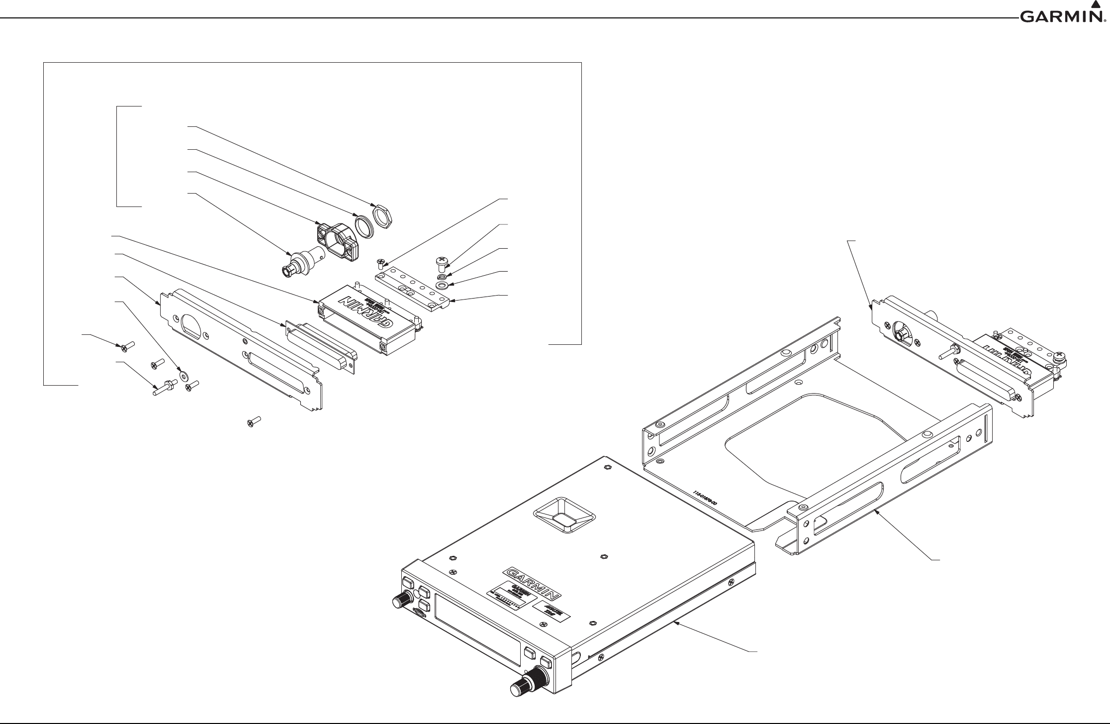
190-01553-00 GTR 200 Installation Manual
Revision G Page C-2
APPENDIX C Outline and Installation Drawings
Figure C-2 GTR 200 Assembly Drawing
115-01878-00
GTR200 RACK
GTR200 UNIT
011-02980-00
GTR200 CONNECTOR KIT
011-03240-00
212-20065-00
212-00018-04
211-60209-09
330-00053-01
BAGGED KIT
233-00087-00
330-00053-01
THESE FOUR ITEMS
125-00165-00
PRE-ASSEMBLED
PROVIDED
212-00022-00
PART OF
330-00625-37
115-01879-00
011-00950-03
QTY 4
212-00024-04
011-03240-00
CONNECTOR KIT
117-00147-01
211-63234-10
211-63234-08
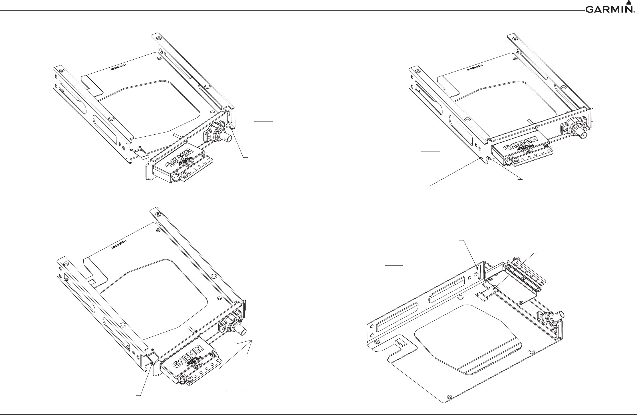
190-01553-00 GTR 200 Installation Manual
Revision G Page C-3
APPENDIX C Outline and Installation Drawings
Figure C-3 GTR 200 Installation Drawing
FOLLOWING CONNECTOR KIT ASSEMBLY,
INSERT TAB OF CONNECTOR PLATE INTO
RACK SLOT AS SHOWN.
STEP 1
STEP 2
SLIGHTLY DEPRESS RETAINING
SPRING AND INSERT CONNECTOR
PLATE PARALLEL TO REAR OF RACK.
SLIDE CONNECTOR PLATE
STEP 3
INTO THIS SLOT UNTIL RETAINING
SPRING SNAPS INTO PLACE.
TAB IN PLACE
RESULT
RETAINING SPRING
IN PLACE
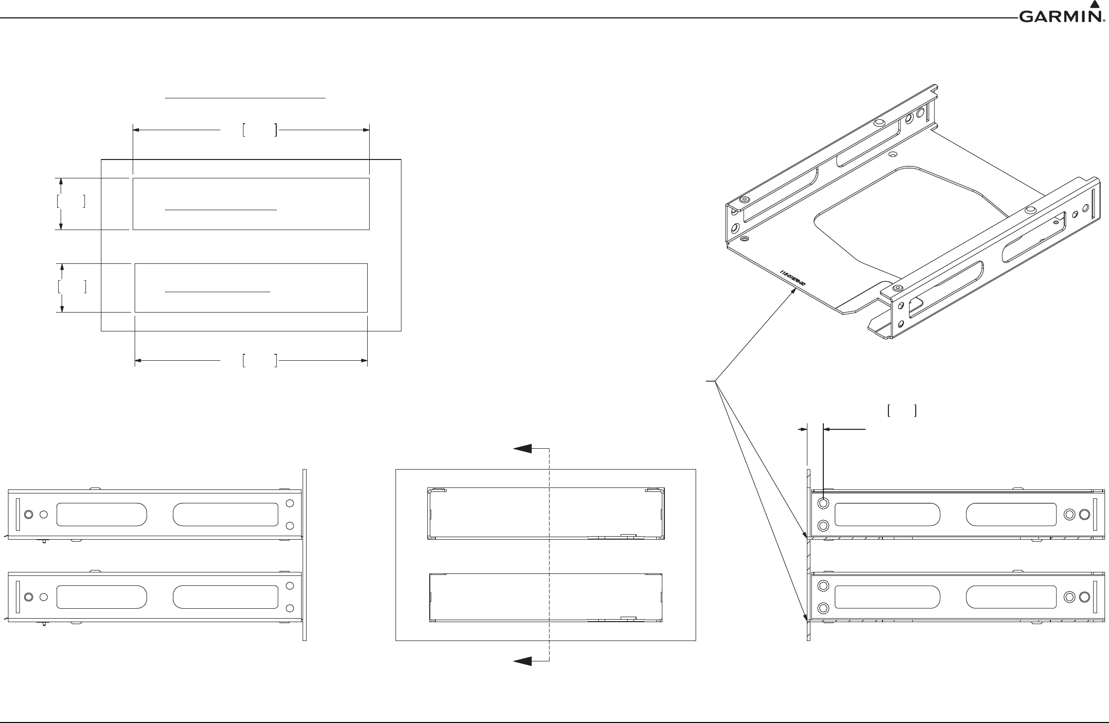
190-01553-00 GTR 200 Installation Manual
Revision G Page C-4
APPENDIX C Outline and Installation Drawings
Figure C-4 GTR 200 Panel Cutout Drawing
RECOMMENDED PANEL CUTOUT
NOTE:
FRONT EDGE OF RACK
LIP MUST BE FLUSH WITH
THE FRONT OF THE
AIRCRAFT PANEL
A
A
REAR INSERTED RACK
FRONT INSERTED RACK
6.31 160.3
34.9
1.38
32.8
1.29
6.20 157.5
SECTION A-A
.437 11.1 TYPICAL
DISTANCE FROM
FRONT OF PANEL
TO MOUNTNG HOLES
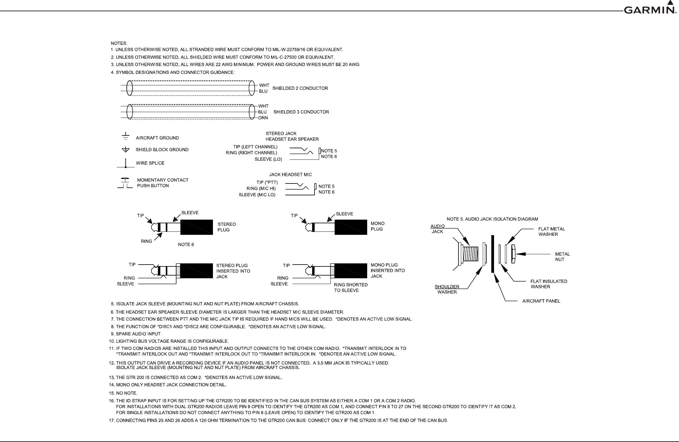
190-01553-00 GTR 200 Installation Manual
Revision G Page D-1
APPENDIX D Interconnect Examples
Figure D-1 GTR 200 Interconnect Example Notes
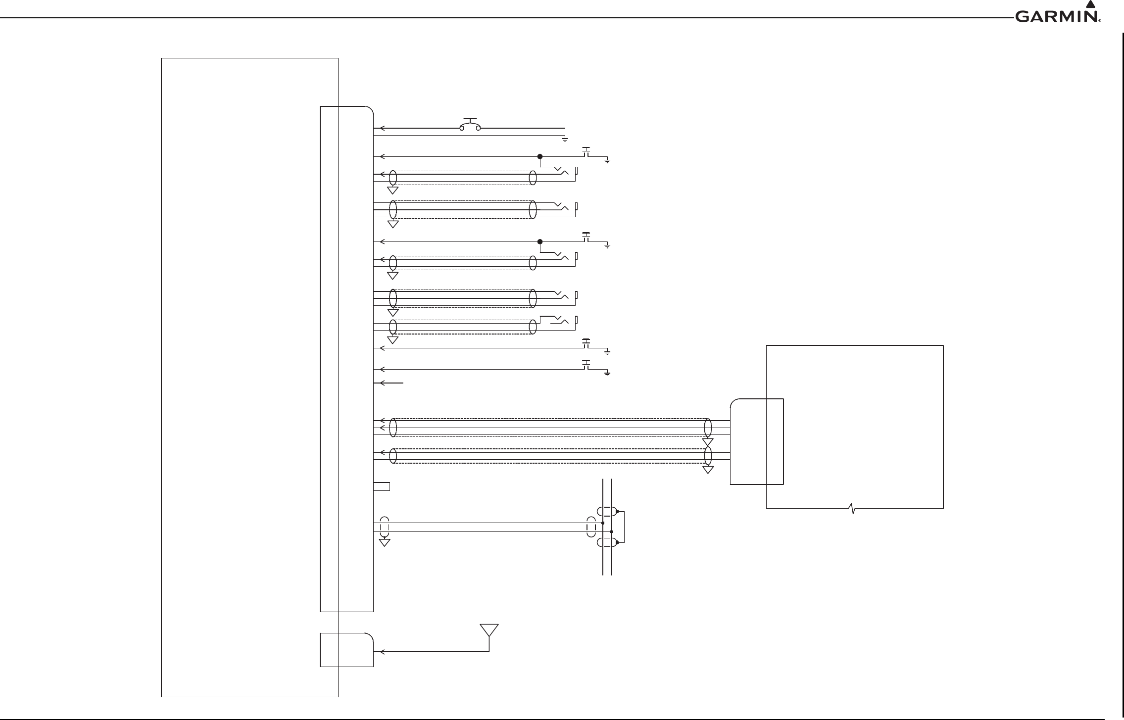
190-01553-00 GTR 200 Installation Manual
Revision G Page D-2
APPENDIX D Interconnect Examples
Figure D-2 GTR 200- Power & Ground/Intercom/GDU 37X/46X CAN Bus Interconnect Example
STEREOAUDIO OUT LE FT
19 STEREO AUDIO O U TR IGH T
STEREOAUDIOOUTLO
20
M ONOAUDIO OUTHI
M ONO AUDIOOUT LO
1
18
GARMIN GDU 37XGARMIN GDU 37X
GTR 200GTR 200
J2001J2001
NOTE 7NOTE 7
NOTE 7NOTE 7
USE 20 AWG FOR POWER AND GROUNDUSE 20 AWG FOR POWER AND GROUND
14/28V AVIONICS POWER BUS14/28V AVIONICS POWER BUS
PILOT PUSH TO TALKPILOT PUSH TO TALK
NOTE 5NOTE 5
PILOT MIC JACKPILOT MIC JACK
NOTE 5NOTE 5
PILOT HEADSET JACKPILOT HEADSET JACK
COPILOT PUSH TO TALKCOPILOT PUSH TO TALK
NOTE 5NOTE 5
COPILOT MIC JACKCOPILOT MIC JACK
NOTE 5NOTE 5
COPILOT HEADSET JACKCOPILOT HEADSET JACK
NOTE 12NOTE 12
RECORDER OUTPUTRECORDER OUTPUT
NOTE 8NOTE 8
NOTE 8NOTE 8
NOTE 9NOTE 9
NOTE 11NOTE 11
5A CIRCUIT BREAKER 28V AIRCRAFT5A CIRCUIT BREAKER 28V AIRCRAFT
7.5A CIRCUIT BREAKER 14V AIRCRAFT7.5A CIRCUIT BREAKER 14V AIRCRAFT
GARMINGARMIN
P2002P2002
COM ANTENNACOM ANTENNA
P2001P2001
1
3
23
2
0
3
11
2
1
43
61
5
1
33
3
1
4
1
6
3
7
1
5
3
02
O
L
T
U
O
O
I
D
U
A
R
EVI
E
C
E
R
I
H
TU
O
O
I
DU
AR
E
V
I
E
C
E
R
O
L
NIO
I
D
U
A1
X
U
A
IHN
IO
IDU
A1
X
U
A
O
L
N
I
1C
I
S
UM
T
H
GI
RN
I
1
C
ISU
M
T
F
ELN
I
1C
I
S
U
M
2
C
S
I
D*
1
C
S
I
D
*
O
L
T
ES
D
A
E
H
T
OL
I
P
O
C
T
H
GI
R
T
E
S
D
A
E
H
T
OL
I
P
O
C
T
F
EL
T
E
S
D
A
E
H
TOL
I
P
O
C
T
O
L
I
P
O
C
T
T
P
*
OL
C
I
M
TOL
I
P
OC
I
HC
IM
TOL
I
P
O
C
O
LT
ES
D
A
E
H
T
O
L
I
P
T
H
G
I
R
T
E
S
D
A
E
H
T
O
L
I
P
T
F
EL
TES
D
A
E
H
T
O
L
I
P
T
O
L
I
P
T
T
P*
1
OLC
I
M
T
O
L
I
P
I
HC
IM
T
O
L
I
P
D
N
G
R
E
W
O
P
R
E
WO
P
s
1919
1818
3737
2222
2929
1010
CAN BUS LOCAN BUS LO
CAN BUS HICAN BUS HI
CAN TERM ACAN TERM A
CAN TERM BCAN TERM B
6
7
26
26
2525
*TRANSMIT INTERLOCK IN*TRANSMIT INTERLOCK IN
*TRANSMIT INTERLOCK OUT*TRANSMIT INTERLOCK OUT
5
4
28
28
9
O
L
N
IO
I
D
U
A2XU
A
I
HN
I
O
I
D
U
A
2
X
U
A
TO LIGHTING BUS NOTE 10
TO LIGHTING BUS NOTE 10
TIE TOGETHER TO IDENTIFY GTR AS COM 2.TIE TOGETHER TO IDENTIFY GTR AS COM 2.
2727
8ID INID IN
ID LOID LO
LIGHTING BUSLIGHTING BUS 3
GARMIN GDU 46XGARMIN GDU 46X
REQUIRED WHEN LOCATED ATREQUIRED WHEN LOCATED AT
A END OF THE CAN BUS. SEE NOTE 17.A END OF THE CAN BUS. SEE NOTE 17.
SEE NOTE 16.SEE NOTE 16.
GDU 46X J4501GDU 46X J4501
GDU 46X P4501GDU 46X P4501
GDU 37X J3701GDU 37X J3701GDU 37X P3701GDU 37X P3701
CAN NODE LENGTH 0.3 METER MAXIMUMCAN NODE LENGTH 0.3 METER MAXIMUM
J2002J2002
s
s
s
s
s
s
s
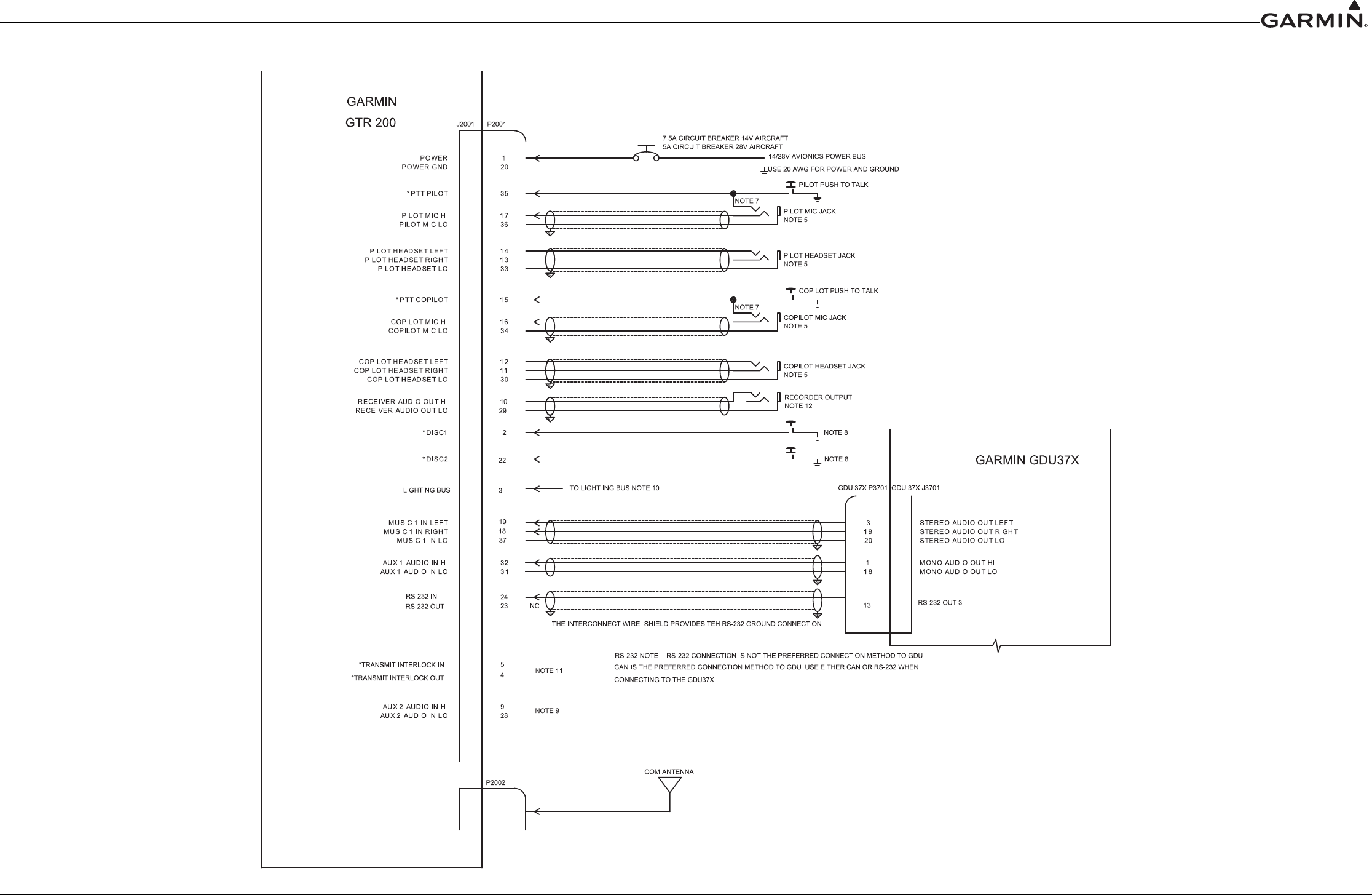
190-01553-00 GTR 200 Installation Manual
Revision G Page D-3
APPENDIX D Interconnect Examples
Figure D-3 GTR 200- Power & Ground/Intercom/GDU 37X RS-232 Interconnect Example
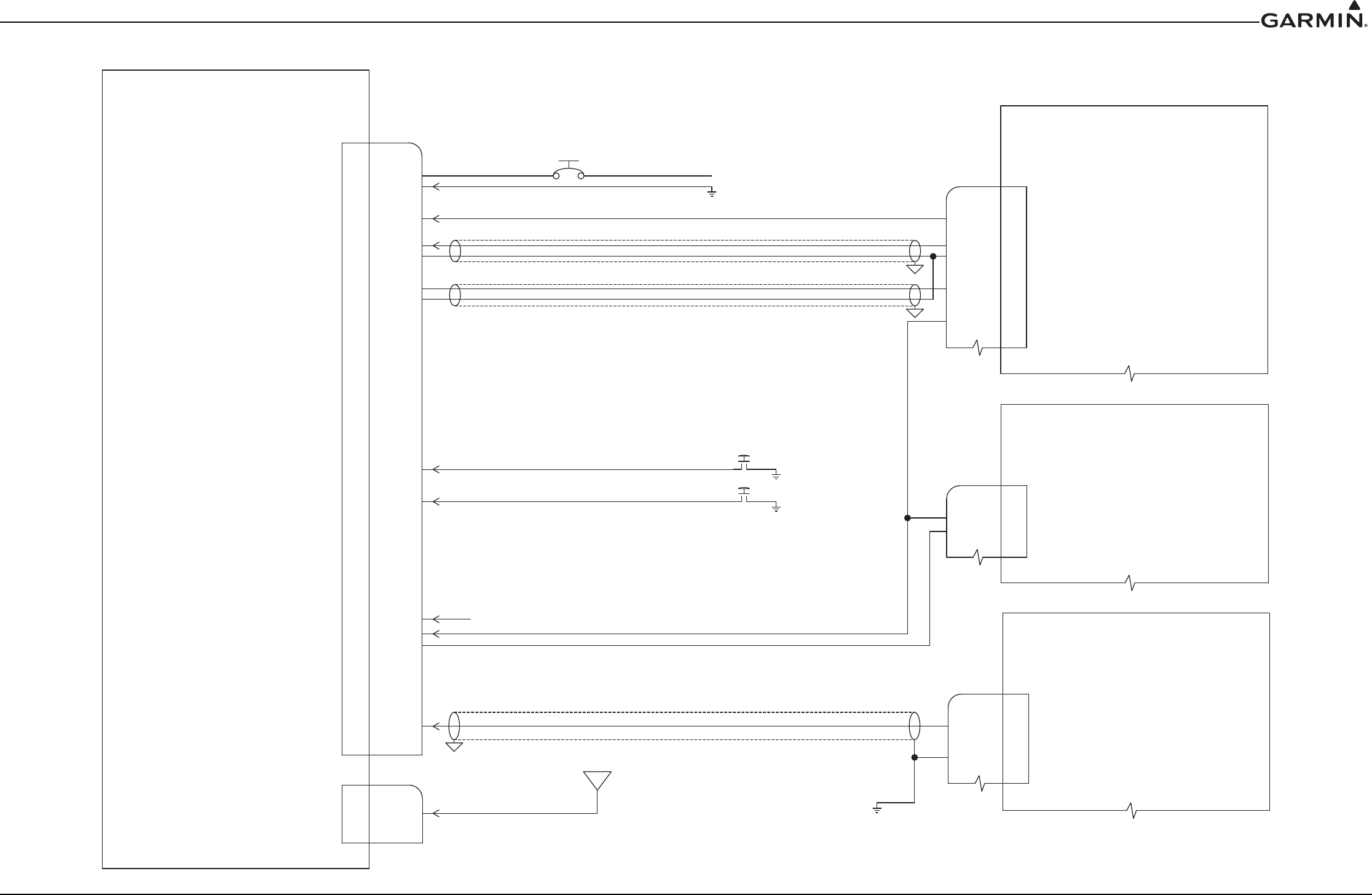
190-01553-00 GTR 200 Installation Manual
Revision G Page D-4
APPENDIX D Interconnect Examples
Figure D-4 GTR 200- Power & Ground/GMA 240/GNS 430/aera 79X Interconnect Example
s
POWER
POWER GND
PILOT MIC HI
PILOT MIC LO
1
*PTT PILOT
PILOT HEADSET LEFT
PILOT HEADSET RIGHT
PILOT HEADSET LO
COPILOT MIC HI
COPILOT MIC LO
*PTT COPILOT
COPILOT HEADSET LEFT
COPILOT HEADSET RIGHT
COPILOT HEADSET LO
RECEIVER AUDIO OUT HI
RECEIVER AUDIO OUT LO
20
35
17
36
10
10
29
29
15
15
16
34
12
11
30
MUSIC 1 IN LEFT
MUSIC 1 IN RIGHT
MUSIC 1 IN LO
AUX 1 AUDIO IN HI
AUX 1 AUDIO IN LO
AUX 2 AUDIO IN HI
AUX 2 AUDIO IN LO
19
18
37
32
31
9
28
P2001
P2001
GARMIN
GARMIN
7.5A CIRCUIT BREAKER 14V AIRCRAFT
7.5A CIRCUIT BREAKER 14V AIRCRAFT
5A CIRCUIT BREAKER 28V AIRCRAFT
5A CIRCUIT BREAKER 28V AIRCRAFT
*DISC1
*DISC2
2
22
NOTE 8
NOTE 8
NOTE 8
NOTE 8
AVIONICS POWER BUS
AVIONICS POWER BUS
USE 20 AWG FOR POWER AND GROUND
USE 20 AWG FOR POWER AND GROUND
J2001
J2001
COM ANTENNA
COM ANTENNA
P2002
P2002
GTR 200
GTR 200
LIGHTING BUS
*TRANSMIT INTERLOCK IN
*TRANSMIT INTERLOCK OUT
3
5
4
TO LIGHTING BUS NOTE 10
TO LIGHTING BUS NOTE 10
RS-232 IN
RS-232 OUT NC
24
23
4
COM MIC KEY
COM MIC KEY
14
TRANSMIT INTERLOCK
TRANSMIT INTERLOCK
GARMIN
GARMIN
GNS 430
GNS 430
J4002
J4002
P4002
P4002
30
30
COM 2 MIC KEY* OUT
COM 2 MIC KEY* OUT
15
COM 2 MIC AUDIO OUT HI
COM 2 MIC AUDIO OUT HI
COM 2 AUDIO LO
COM 2 AUDIO LO
14
14
COM 2 AUDIO IN HI
COM 2 AUDIO IN HI
13
13
GARMIN
GARMIN
GMA 240
GMA 240
J2401
J2401
P2401
P2401
NOTE 13
NOTE 13
14
14
13
13
33
33
NC
NC
NC
NC
NC
NC
NC
NC
NC
NC
NC
NC
NC
NC
NC
NC
NC
NC
COM 1 MIC KEY* OUT
COM 1 MIC KEY* OUT12
O
TX2 (DATA OUT) ORANGE WIRE
TX2 (DATA OUT) ORANGE WIRE
GARMIN
GARMIN
AERA 79X
AERA 79X
B
POWER GROUND/DATA GROUND BLACK WIRE
POWER GROUND/DATA GROUND BLACK WIRE
NC
NC
NC
NC
NC
NC
NC
NC
NC
NC
NC
NC
NC
NC
NOTE 15
NOTE 15
J2002
J2002
s
s
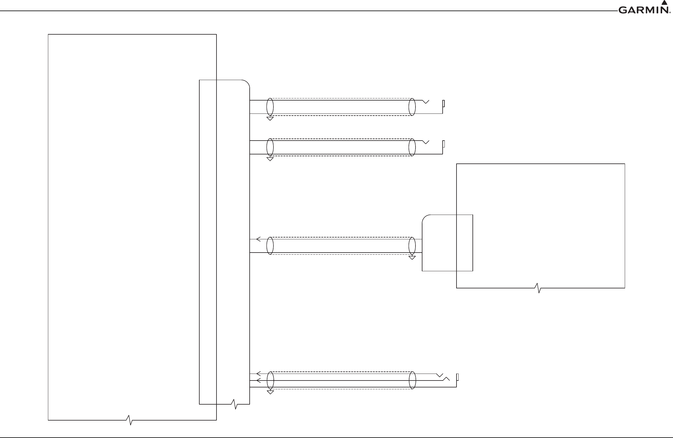
190-01553-00 GTR 200 Installation Manual
Revision G Page D-5
APPENDIX D Interconnect Examples
Figure D-5 GTR 200- Mono Audio/Remote Mount Jack Interconnect Example
PILOT HEADSET LEFT
PILOT HEADSET RIGHT
PILOT HEADSET LO
COPILOT HEADSET LEFT
COPILOT HEADSET RIGHT
COPILOT HEADSET LO
12
11
30
MUSIC 1 IN LEFT
MUSIC 1 IN RIGHT
MUSIC 1 IN LO
19
18
37
P2001
P2001
GARMIN
GARMIN
J2001
J2001
GTR 200
GTR 200
14
14
13
13
33
33 s
NC
NC
PILOT HEADSET JACK
PILOT HEADSET JACK
NOTE 5 NOTE 14
NOTE 5 NOTE 14
NC
NC
COPILOT HEADSET JACK
COPILOT HEADSET JACK
NOTE 5 NOTE 14
NOTE 5 NOTE 14
MONO CONNECTIONS
MONO CONNECTIONS
MUSIC 1 IN LEFT
MUSIC 1 IN RIGHT
MUSIC 1 IN LO
19
18
37
MONO AUDIO OUT HI
MONO AUDIO OUT HI
MONO AUDIO SOURCE
MONO AUDIO SOURCE
NC
NC
MONO AUDIO OUT LO
MONO AUDIO OUT LO
MUSIC INPUT USING REMOTE MOUNT JACK
MUSIC INPUT USING REMOTE MOUNT JACK
NOTE 5
NOTE 5
s
s
s
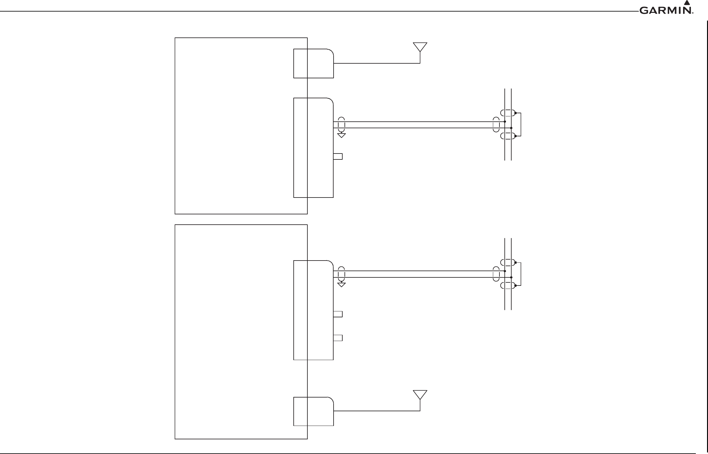
190-01553-00 GTR 200 Installation Manual
Revision G Page D-6
APPENDIX D Interconnect Examples
Figure D-6 GTR 200/CAN Bus Interconnect Drawing
COM ANTENNACOM ANTENNA
CAN BUS LOCAN BUS LO
CAN BUS HICAN BUS HI
CAN TERM ACAN TERM A
CAN TERM BCAN TERM B
6
7
26
26
2525
LEAVE OPEN TO IDENTIFY GTR AS COM 1. LEAVE OPEN TO IDENTIFY GTR AS COM 1.
SEE NOTE 16SEE NOTE 162727
8
ID IN
ID IN
ID LOID LO
P2001P2001
GARMINGARMIN
J2001J2001
P2002P2002
GTR 200 AS COM 1GTR 200 AS COM 1
P2001P2001
GARMINGARMIN
J2001J2001
COM ANTENNACOM ANTENNA
P2002P2002
GTR 200 AS COM 2GTR 200 AS COM 2
COM ANTENNACOM ANTENNA
CAN BUS LOCAN BUS LO
CAN BUS HICAN BUS HI
6
7
P2001
P2001
J2001J2001
JUMPER REQUIRED WHEN LOCATED ATJUMPER REQUIRED WHEN LOCATED AT
END OF THE CAN BUS. SEE NOTE 17.END OF THE CAN BUS. SEE NOTE 17.
S
CAN NODE LENGTH 0.3 METER MAXIMUMCAN NODE LENGTH 0.3 METER MAXIMUM
S
CAN NODE LENGTH 0.3 METER MAXIMUMCAN NODE LENGTH 0.3 METER MAXIMUM
J2002J2002
J2002J2002
2727
8ID INID IN
ID LOID LO
CAN TERM ACAN TERM A
CAN TERM BCAN TERM B
2626
2525
TIE TOGETHER TO IDENTIFY GTR AS COM 2.TIE TOGETHER TO IDENTIFY GTR AS COM 2.
SEE NOTE 16.SEE NOTE 16.
JUMPER REQUIRED WHEN LOCATED ATJUMPER REQUIRED WHEN LOCATED AT
END OF THE CAN BUS. SEE NOTE 17.END OF THE CAN BUS. SEE NOTE 17.
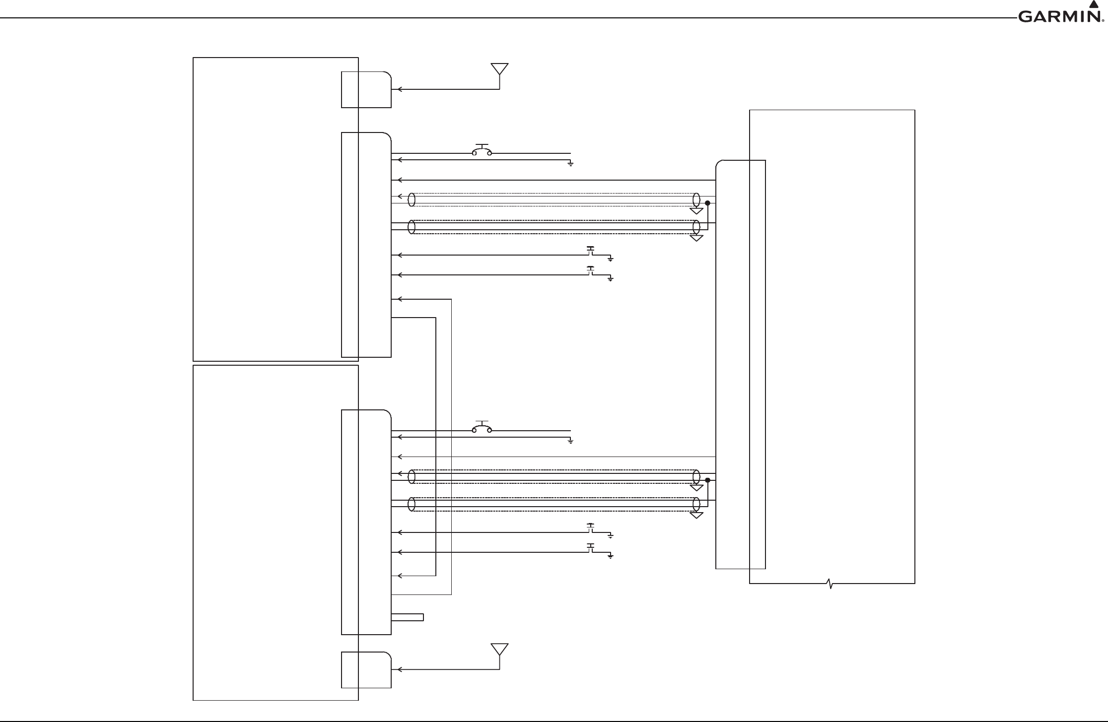
190-01553-00 GTR 200 Installation Manual
Revision G Page D-7
APPENDIX D Interconnect Examples
Figure D-7 Dual GTR 200/GMA 240 Interconnect Drawing
PO WER
PO W ER GND
PILO TMICHI
PILO T M ICLO
1
*P T T PILO T
RE CEIVE R AUDIOO U T HI
R E CE IVERAUD IOOU T LO
20
35
17
36
10
10
29
29
P2001
P2001
GARMIN
GARMIN
7.5A CIRCUIT BREAKER 14V AIRCRAFT
7.5A CIRCUIT BREAKER 14V AIRCRAFT
5A CIRCUIT BREAKER 28V AIRCRAFT
5A CIRCUIT BREAKER 28V AIRCRAFT
*DISC1
*
DISC2
2
22
NOTE 8
NOTE 8
NOTE 8
NOTE 8
AVIONICS POWER BUS
AVIONICS POWER BUS
USE 20 AWG FOR POWER AND GROUND
USE 20 AWG FOR POWER AND GROUND
J2001
J2001
COM ANTENNA
COM ANTENNA
P2002
P2002
GTR 200 AS COM 1
GTR 200 AS COM 1
5
4
12
12
COM 1 MIC KEY* OUT
COM 1 MIC KEY* OUT
11
11
COM 1 MIC AUDIO OUT HI
COM 1 MIC AUDIO OUT HI
COM 1 AUDIO LO
COM 1 AUDIO LO
10
10
COM 1 AUDIO IN HI
COM 1 AUDIO IN HI9
GARMIN
GARMIN
GMA 240
GMA 240
J2401
J2401
P2401
P2401
27
27
8
ID IN
ID IN
ID LO
ID LO
*TRANSMIT INTERLOCK IN
*TRANSMIT INTERLOCK IN
*TRANSMIT INTERLOCK OUT
*TRANSMIT INTERLOCK OUT
POWER
PO W ER GND
PILO T MIC HI
PILOT M ICLO
1
*P T T PILO T
R E CE IVE R AUD IO O U T HI
R E CE IVE R AUD IOO U T LO
20
35
17
36
10
10
29
29
P2001
P2001
GARMIN
GARMIN
7.5A CIRCUIT BREAKER 14V AIRCRAFT
7.5A CIRCUIT BREAKER 14V AIRCRAFT
5A CIRCUIT BREAKER 28V AIRCRAFT
5A CIRCUIT BREAKER 28V AIRCRAFT
*DISC1
*DISC2
2
22
NOTE 8
NOTE 8
NOTE 8
NOTE 8
AVIONICS POWER BUS
AVIONICS POWER BUS
USE 20 AWG FOR POWER AND GROUND
USE 20 AWG FOR POWER AND GROUND
J2001
J2001
COM ANTENNA
COM ANTENNA
P2002
P2002
5
4
30
30
COM 2 MIC KEY* OUT
COM 2 MIC KEY* OUT
15
COM 2 MIC AUDIO OUT HI
COM 2 MIC AUDIO OUT HI
COM 2 AUDIO LO
COM 2 AUDIO LO
14
14
COM 2 AUDIO IN HI
COM 2 AUDIO IN HI
13
13
27
27
8
ID IN
ID IN
ID LO
ID LO
*TRANSMIT INTERLOCK IN
*TRANSMIT INTERLOCK IN
*TRANSMIT INTERLOCK OUT
*TRANSMIT INTERLOCK OUT
GTR 200 AS COM 2
GTR 200 AS COM 2
TIE TOGETHER TO IDENTIFY GTR AS COM 2.
TIE TOGETHER TO IDENTIFY GTR AS COM 2.
SEE NOTE 16.
SEE NOTE 16.
LEAVE OPEN
LEAVE OPEN
TO IDENTIFY
TO IDENTIFY
AS COM 1.
AS COM 1.
SEE NOTE 16
SEE NOTE 16
J2002
J2002
J2002
J2002
S
S
S
S
190-01553-00 GTR 200 Installation Manual
Revision G Page D-8
APPENDIX D Interconnect Examples
Figure D-8 GTR 200- J2001 Connector Layout
CCOPILOT
HS LO
30
30
8
AUX M
ONO
ONO
IN 2
IN 2
9
RECEI
EIVER R
AUDIO LO
29
29
RECEIEIVER R
AUDIO
OU
OUT
HI
10
10
COPILOT
HS RIGHT
11
11
COPILOT
HS LEFT
12
12 1313
AUX M
ONO
ONO
IN 1
32
32
AUX 1 LO
31
312727
AUX 2 LO
28
28
COPILOT
MIC
C LO
34
34
PILOT HS S
LO
33
33
RS232
RS232 IN
2424 2525 2626
MUSIC C LO
37
37
PILOT HS S
LEFT
1414
COPILOT
PTT
15
15
MUSIC C IN
LEFT
19
19
MUSIC C IN
RIGHT
18
18
PILOT MIC
IN
17
17
PILOT PTT
35
35
PILOT MIC
LO
36
36
COPILOT
MIC
C IN
16
16
PILOT HS S
RIGHT
TX
TX
INTERLO
CK
CK
OUT
OUT
4 5 7
CAN BUS
CAN BUS
LOLO
6
TX
TX
INTERLO
CK
CK
IN
IN
DISC C 1
2
RS232
RS232 OUOUT
23
23
AIRCRARAFT
GROUND
GROUND
2020
AIRCRARAFT
POWER
POWER
1
LIGHTING
BUS IN
BUS IN
3
SPARE
SPARE
2121
DISC C 2
22
22
J2001 AS VIEWED LOOKING AT REAR OF UNITJ2001 AS VIEWED LOOKING AT REAR OF UNIT
CAN BUSCAN BUS
HIHI
CAN CAN
TERM BTERM B
CAN CAN
TERM ATERM A
ID LOID LO
ID INID IN
