GasSecure AS GS01AA Wireless gas detector User Manual GasSecure GS01 Hardware Manual
GasSecure AS Wireless gas detector GasSecure GS01 Hardware Manual
Contents
- 1. Users Manual
- 2. user manual
user manual

GasSecure GS01 and GS01-EA
Wireless Infrared Hydrocarbon
Gas Detector
User Manual
(For firmware version ≥ 3.3)
Document ID: 112464 Contact info
Release: 9 GasSecure AS
Version: 145 Hoffsveien 70 C
Doc. Status: APPROVED N-0377 Oslo
Last modified: 26.04.2017 Norway
www.gassecure.com
post@gassecure.com

GasSecure GS01
Hardware Manual
I
Note
Those who have or will have the responsibility for the operation or maintenance of
this product must carefully read this manual. The product may not perform as
designed if it is not used and maintained in accordance with the manufacturer’s
instructions.
Please read the complete manual and particularly note the paragraphs having an
exclamation mark in the margin.
This manual covers installation, operation and maintenance of the GS01 wireless
hydrocarbon detector and its battery pack.
The product warranty issued by GasSecure is voided if the product is not used
and maintained as described in this manual.
Please read also the safety instructions in Section 6.
GasSecure AS, all rights reserved.

GasSecure GS01
Hardware Manual
II
PRODUCT DATA
Manufacturer GasSecure AS
Country of origin Norway
Models GS01, GS01-EA
Gases Hydrocarbons
Range Methane configuration 0 – 100% LEL
Range Propane configuration 0 – 80% LEL
Environmental conditions
Operating temperature -30oC to +55oC
Humidity 0 to 90 RH1 non-condensing
Pressure influence, 700 – 1300 hPa2 ≤ 0.15% of reading per hPa
(at 50% LEL)
Protection classification IP 66 and IP 67 3
Storage temperature -40oC to +65oC
Storage pressure 700 to 1300 hPa
Electrical
RF output power GS01 ≤ 12 dBm EIRP
RF output power GS01-EA ≤ 16 dBm EIRP
Battery type Lithium-Thionyl Chloride
Battery cells Tadiran SL-2780/S or TL-5930/S
Average power 5 mW
Explosion Protection II 2G Ex ib IIC T4 Gb -30oC to +55oC
Intrinsic safety temperature -40oC to +65oC
Gas performance temperature -30oC to +55oC
1 The manufacturer verified conditions are 0-100% RH and condensing.
2 Applies only for Methane configuration and outside the pressure range 850 – 1150 hPa: The
process value (PV) must be replaced with the adjusted process value PVadj. PVadj is calculated by
the controller with the measured atmospheric pressure as input according to
formula
( )
PVPV p
p
adj
5.1
0
−
=
, where p is the measured pressure and p0 is the standard atmospheric
pressure (101 kPa). Pressure p must be measured with +/-10 kPa accuracy.
3 IP ratings do not imply that the equipment will detect gas during exposure to those conditions.

GasSecure GS01
Hardware Manual
III
TABLE OF CONTENTS
1. PRODUCT DESCRIPTION ........................................................................................................5
1.1 GENERAL .................................................................................................................................5
1.2 MEASURING PRINCIPLE .............................................................................................................5
1.3 INSTRUMENT DESCRIPTION ........................................................................................................6
1.4 BATTERY ..................................................................................................................................6
1.5 OUTLINE DIMENSIONS ...............................................................................................................6
2. INSTALLATION ..........................................................................................................................9
2.1 TOOLS .....................................................................................................................................9
2.2 MOUNTING ...............................................................................................................................9
2.3 GROUNDING ...........................................................................................................................10
2.4 SUN SHADE / WEATHER PROTECTION .......................................................................................10
2.5 EXTERNAL ANTENNA (APPLIES ONLY FOR GS01-EA) ................................................................10
3. COMMISSIONING ....................................................................................................................12
3.1 COMMUNICATION ....................................................................................................................12
3.2 ISA100 WIRELESS™ STANDARD .............................................................................................12
3.3 ISA100 OBJECTS ....................................................................................................................12
3.4 GS01 DATA FORMAT DETAILS ..................................................................................................14
3.5 MODIFICATION OF LEL ............................................................................................................14
3.6 COMMUNICATION MONITORING ................................................................................................15
3.7 GS01 DETECTOR PROVISIONING .............................................................................................15
3.8 MODIFICATIONS TO AN EXISTING NETWORK ..............................................................................18
3.9 VISUAL AND FUNCTIONAL CHECK .............................................................................................19
4. OPERATION .............................................................................................................................20
4.1 NORMAL OPERATION ...............................................................................................................20
4.2 PROOF TEST (VALIDATION)......................................................................................................20
5. MAINTENANCE .......................................................................................................................22
5.1 ROUTINE MAINTENANCE ..........................................................................................................22
5.2 SPARE PARTS AND ACCESSORIES ............................................................................................22
5.3 CLEANING ..............................................................................................................................23
5.4 BATTERY PACK .......................................................................................................................23
5.5 STORAGE ...............................................................................................................................26
5.6 TROUBLESHOOTING ................................................................................................................26
5.7 CONTACT GASSECURE FOR SUPPORT .....................................................................................27
6. SAFETY INSTRUCTIONS ........................................................................................................29
7. CERTIFICATIONS AND STANDARDS ....................................................................................30
7.1 STANDARDS ...........................................................................................................................30
7.2 REGULATORY COMPLIANCE OF RADIO FOR GS01 .....................................................................31
7.3 MARKING ...............................................................................................................................31
8. TECHNICAL DATA ..................................................................................................................35
8.1 PERFORMANCE CHARACTERISTICS ..........................................................................................35
8.2 CROSS SENSITIVITIES .............................................................................................................36
9. REFERENCES .........................................................................................................................38
10. APPENDIX ...........................................................................................................................39

GasSecure GS01
Hardware Manual
IV
FIGURES
FIGURE 1-1: GS01 DETECTOR LAYOUT................................................................................................................ 6
FIGURE 1-2: GS01 DETECTOR WITH DIMENSIONS IN [MM] ................................................................................... 7
FIGURE 1-3: GS01-EA DETECTOR WITH DIMENSIONS IN [MM] ............................................................................ 8
FIGURE 1-4: GS01 MEASURING CELL DETAILS ..................................................................................................... 8
FIGURE 2-1: CORRECT POSITION OF THE WEATHER CAP AND LOCATION OF EARTH POINT. ................................. 10
FIGURE 2-2: GS01-EA LAYOUT WITH ANTENNA CONNECTIONS ........................................................................ 11
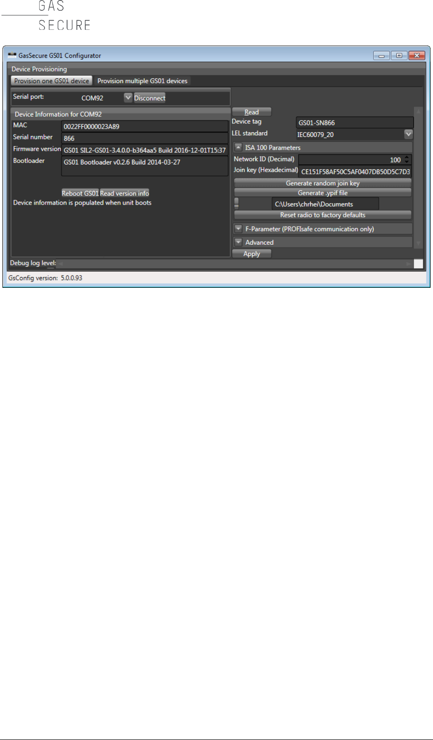
FIGURE 3-1: GS01 CONFIGURATOR ................................................................................................................... 17
FIGURE 5-1: BATTERY PACK WARNING LABEL ................................................................................................... 24
FIGURE 5-2: BATTERY PACK BOTTOM VIEW ...................................................................................................... 25
FIGURE 5-3: BATTERY PACK TOP AND BOTTOM ................................................................................................. 25
FIGURE 7-1: GS01 PRODUCT IDENTIFICATION PLATE ......................................................................................... 31
FIGURE 7-2: GS01-EA PRODUCT IDENTIFICATION PLATE .................................................................................. 32
FIGURE 7-3: GS01 PRODUCT IDENTIFICATION PLATE – FM APPROVED .............................................................. 32
FIGURE 7-4: GS01-EA PRODUCT IDENTIFICATION PLATE – FM APPROVED ....................................................... 32
FIGURE 7-5: FCC COMPLIANCE LABEL .............................................................................................................. 33
FIGURE 7-6: BATTERY PACK IDENTIFICATION LABEL (FM APPROVED VERSION TO THE RIGHT) ......................... 34
FIGURE 7-7: ANTENNA IDENTIFICATION LABEL (FM APPROVED VERSION TO THE RIGHT) .................................. 34
FIGURE 10-1: EU DECLARATION OF CONFORMITY FOR GS01 AND GS01-EA ................................................... 42
TABLES
TABLE 2-1: PROPERTIES OF STANDARD ANTENNA CABLE FOR THE GS01-EA ................................................... 11
TABLE 3-1: ISA100 OBJECTS ............................................................................................................................ 13
TABLE 3-2: LEL VALUES IN [% VOL] ACCORDING TO IEC AND NIOSH ............................................................ 14
TABLE 3-3: PV GAS MEASUREMENT DATA INTEGRITY ...................................................................................... 15
TABLE 4-1: RECOMMENDED GAS CONCENTRATIONS FOR VALIDATION .............................................................. 21
TABLE 5-1: IMPORTANT SPARE PARTS AND ACCESSORIES FOR THE GS01 ......................................................... 22
TABLE 5-2: STATUS MESSAGES RETRIEVED FROM THE DIAG_STATUS ATTRIBUTE ............................................ 27
TABLE 7-1: LIST OF APPLICABLE STANDARDS FOR THE GS01 ............................................................................ 30
TABLE 8-1: PERFORMANCE CHARACTERISTICS FOR THE GS01.......................................................................... 35
TABLE 8-2: LEL VALUES IN [% VOL] ACCORDING TO IEC60079-20. ................................................................ 36
TABLE 8-3: CROSS SENSITIVITIES FOR A GS01 METHANE DETECTOR. ............................................................... 36
TABLE 8-4: CROSS SENSITIVITIES FOR A GS01 PROPANE DETECTOR. ................................................................ 36
TABLE 8-5: LEL VALUES IN [% VOL] ACCORDING TO NIOSH. .......................................................................... 36
TABLE 8-6: CROSS SENSITIVITIES FOR A GS01 METHANE DETECTOR. ............................................................... 37
TABLE 8-7: CROSS SENSITIVITIES FOR A GS01 PROPANE DETECTOR. ................................................................ 37
TABLE 10-1: PV_STATUS BYTE DESCRIPTION ACCORDING TO ISA100 WIRELESS™ STANDARD....................... 39
TABLE 10-2: CONTENT OF THE DIAG_STATUS ATTRIBUTE ............................................................................ 39

GasSecure GS01
Hardware Manual
DESCRIPTION
5
1. PRODUCT DESCRIPTION
1.1 General
The GS01 is a wireless, battery powered point detector that monitors the
concentration of hydrocarbon gases.
It uses a combination of two sensors:
1. An ultrasonic speed-of-sound sensor that continuously monitors changes in
the ambient air composition.
2. An optical (infrared) absorption sensor that is used for accurate
measurements of the hydrocarbon gas concentration.
The infrared sensor uses more power than the ultrasonic and is therefore kept in
watch mode if the ultrasonic sensor does not detect any changes in the air
composition. The infrared sensor applies optical MEMS (micro electromechanical
system) technology to enable intermittent operation with fast start-up and
measurement, and thus very low average battery consumption.
The measured gas concentration is transmitted wireless using the ISA100
Wireless™ standard. This manual does not cover the wireless router or gateway
and the connected control system (please refer to the list of references in Section
9 providing examples of relevant documentation).
The detector is intrinsically safe, with equipment protection level Gb (Ex ib) (see
Section 7) intended for use in zone 1 and 2 areas.
Two models are available of this gas detector:
- GS01 with fixed antenna
- GS01-EA with extended antenna
All information in this manual for the GS01 also applies for the GS01-EA unless
explicitly otherwise noted.
1.2 Measuring principle
The GS01 detector utilises infrared absorption spectroscopy. The fundament is
the Beer-Lambert Law, which relates the absorption of light to the properties of the
material through which the light is travelling.
The internal radiation source emits infrared radiation through a lens and a
sapphire window into the measuring cell (cf. Figure 1-1 and Figure 1-4). A mirror
at the opposite end of this cell returns the beam back through the sapphire
window into the internal volume of the detector and onto a filter that disperses,
focuses, and modulates the incident light. This filter is a patented silicon MEMS
component proprietary to GasSecure.
By applying a control voltage to the MEMS chip it is switched between the so-
called gas state and the reference state. In the gas state a wavelength where
hydrocarbons do absorb light is focused onto the detector, whereas two
GasSecure GS01
Hardware Manual
6 CHAPTER 1
wavelengths where hydrocarbons do not absorb are focused onto the detector in
the reference state. The GS01 detector uses the same light source, light path and
photodetector for both measurements.
This single beam, triple wavelength detection is unique to the GS01 from
GasSecure.
1.3 Instrument description
The GS01 consists of the main housing (316L stainless steel) with mounting
bracket, the measuring cell, an antenna (note that the GS01-EA features an
antenna connector instead), and the battery compartment (cf. Figure 1-1).
Attached to the main housing are the following detachable parts:
• Weather cap (Polyamide 6)
• Battery cap (Polyamide 6)
• Battery package (Polyamide 6)
Except for these detachable parts, the user shall not disassemble the sensor any
further. When the weather cap is removed, the infrared measuring cell with the
sapphire window on the main housing and the mirror at the outer end, is open and
accessible for cleaning. The ultrasonic sensor is protected by a perforated steel
sheet, which shall not be removed.
1.4 Battery
The GS01 may only be used with the GasSecure battery pack (Part number
10055). The battery pack is designed for two Lithium-Thionyl Chloride size D cells
in series, and has a nominal output voltage of 7.2V. The battery pack has an
internal charge counter. The battery pack is intrinsically safe (see Section 7).
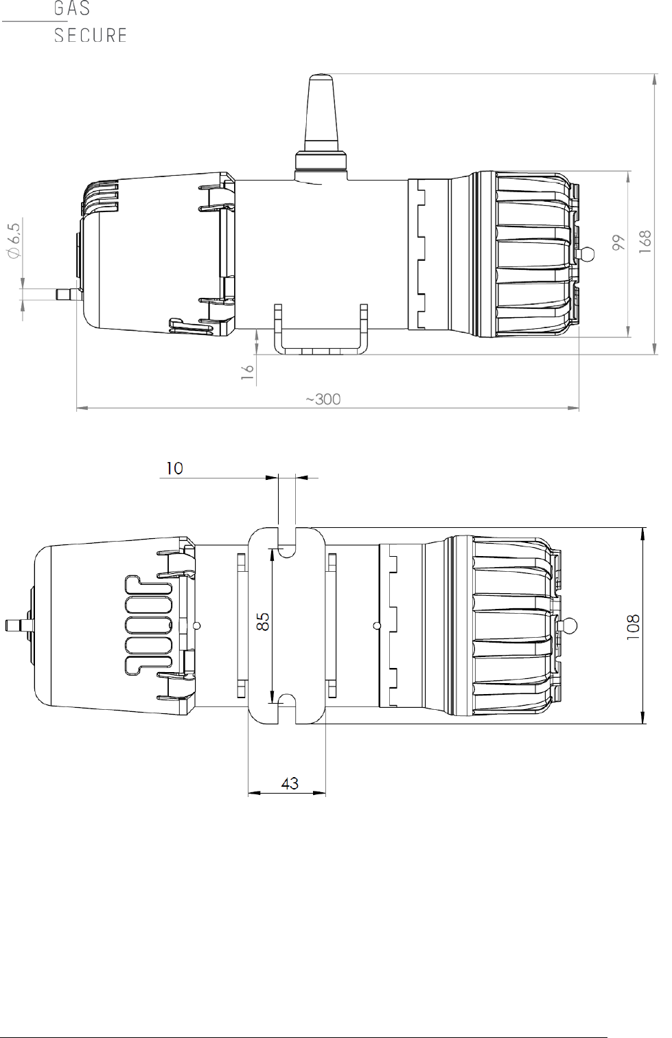
1.5 Outline dimensions
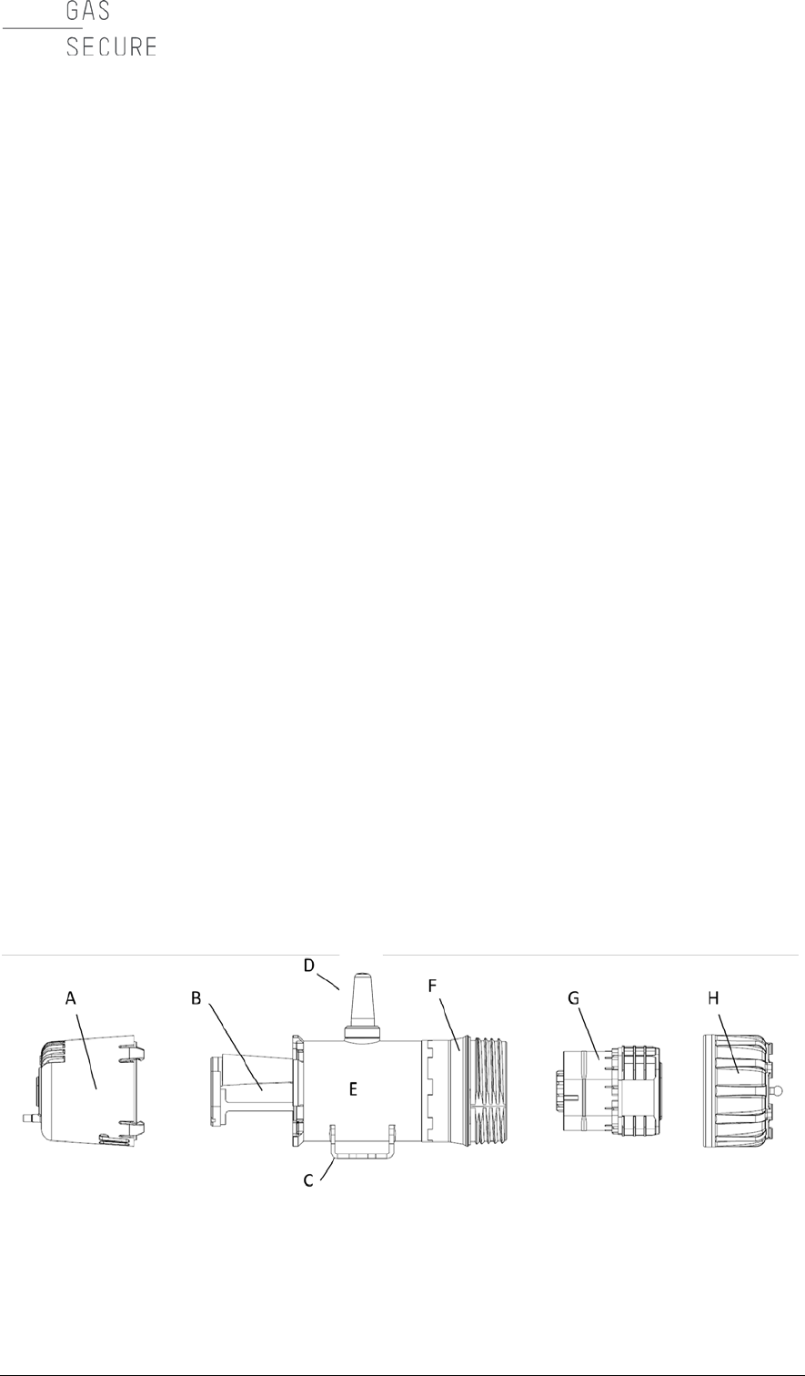
Figure 1-1 shows the sensor buildup with an exploded drawing. Figure 1-2 and
Figure 1-3 depict the GS01 and GS01-EA dimensions, respectively.
Figure 1-1: GS01 detector layout
with A) Weather cap, B) Measuring cell, C) Mounting bracket, D) Antenna, E)
Stainless steel housing, F) Battery compartment, G) Battery pack, H) Battery cap
GasSecure GS01
Hardware Manual
DESCRIPTION
7
Figure 1-2: GS01 detector with dimensions in [mm]
GasSecure GS01
Hardware Manual
8 CHAPTER 1
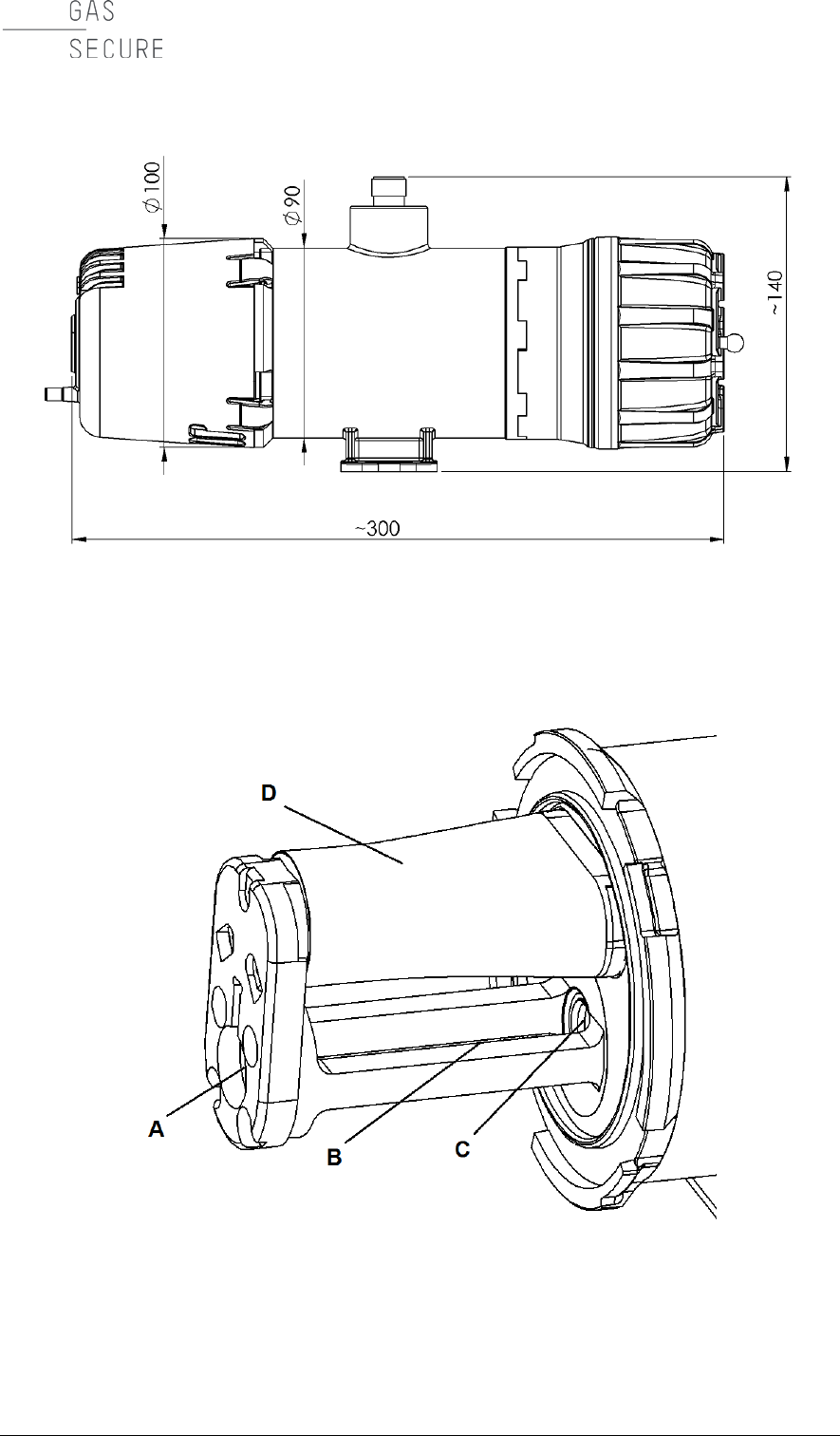
Figure 1-3: GS01-EA detector with dimensions in [mm]
Figure 1-4: GS01 measuring cell details
showing A) External mirror, B) Infrared beam path, C) Sapphire window, D)
Ultrasonic sensor with protective sheet
GasSecure GS01
Hardware Manual
INSTALLATION
9
2. INSTALLATION
Note: The GS01 gas detector certification must comply with the legal requirements
following the area classification at the installation point.
The detector shall be installed where it is most likely to detect gas in the event of a
leakage.
For battery pack installation see Section 5.4.
In areas with significant exposure to direct sunlight and the risk of temperatures
beyond the operating temperature range, a sunshade should be considered (see
list of spare parts in Table 5-1).
2.1 Tools
The following tools are needed to install the instrument:
• Open-end spanner for M8 bolts (alternatively 5/16” bolts)
• Face spanner with two pins in size 75x6 (distance x pin diameter) as
optional tool to remove the battery cap
• Torx screwdriver T10 for battery cell replacement (cf. Section 5.4.2)
2.2 Mounting
The detector is mounted with its long axis horizontally. For the standard GS01
make sure, to the extent possible, that the antenna is vertical (pointing up or
down) and that local radio shadowing is kept at a minimum. The GS01-EA may be
mounted in any horizontal orientation.
Two M8 bolts (alternatively 5/16” bolts) with washers under the head are used to
attach the bracket. The bolts should be spaced from 85 to 95 mm to easily fit the
slots when mounting the detector.
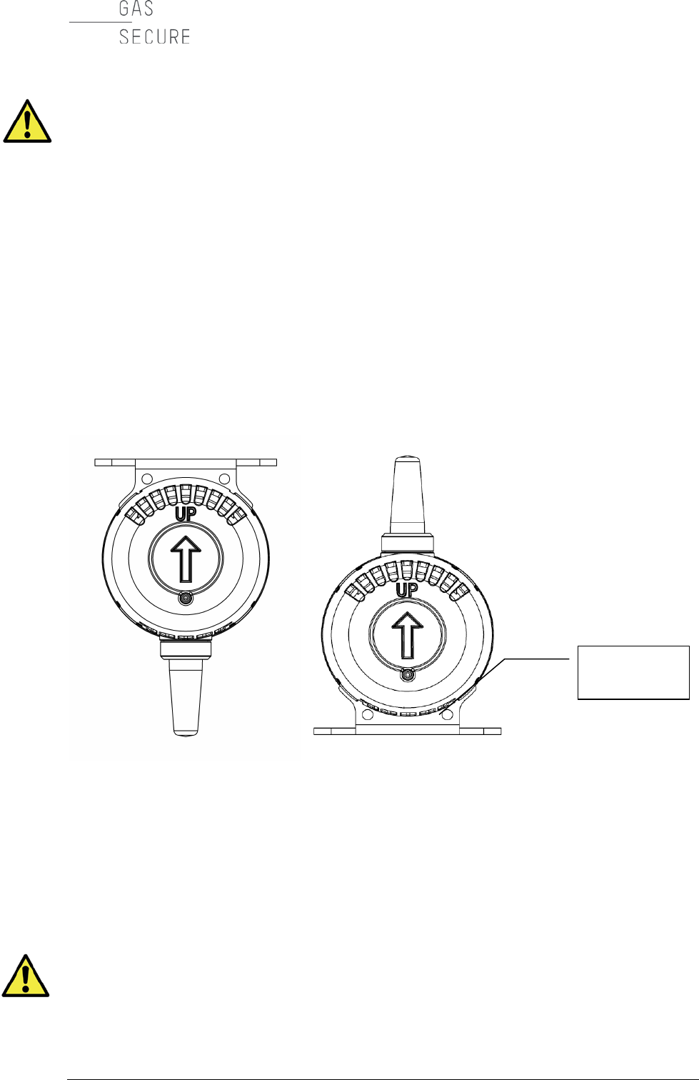
The weather cap must be mounted with the arrow on the cap pointing upwards,
regardless if the antenna is pointing up or down (cf. Figure 2-1). If possible, mount
the GS01 with the weather cap oriented away from the prevailing wind direction.
Do not use the GS01 detector in ventilation ducts or pipes.
Do not mount the detector directly above hot or cold surfaces. If the detector is
mounted inside metallic structures or enclosures the GS01 detector with extended
antenna (GS01-EA) should be considered.
GasSecure GS01
Hardware Manual
10 CHAPTER 2
2.3 Grounding
The detector housing must be connected to ground for operation in hazardous
areas. This to avoid possible static charge build-up, which may arise from
electrically isolated metal parts. Ground the detector either by mounting it on a
grounded metallic structure or by connecting a grounded wire to the screw holes in
the mounting bracket (cf. Figure 2-1).The resistance to ground must be less than
1 GOhm.
2.4 Sun shade / weather protection
The sunshade is available as optional accessory and recommended for locations
with high ambient temperature and / or direct sunlight exposure. It may also be
used as weather protection for instance in locations with frequent heavy
precipitation. The shade is fixed to the gas detector bracket with the same M8 (or
5/16”) bolts, which are used for detector mounting. Make sure that the sunshade
is mounted the correct way so that the detector identification plate remains visible.
Figure 2-1: Correct position of the weather cap and location of earth point.
The arrow must always point up regardless of the detector orientation.
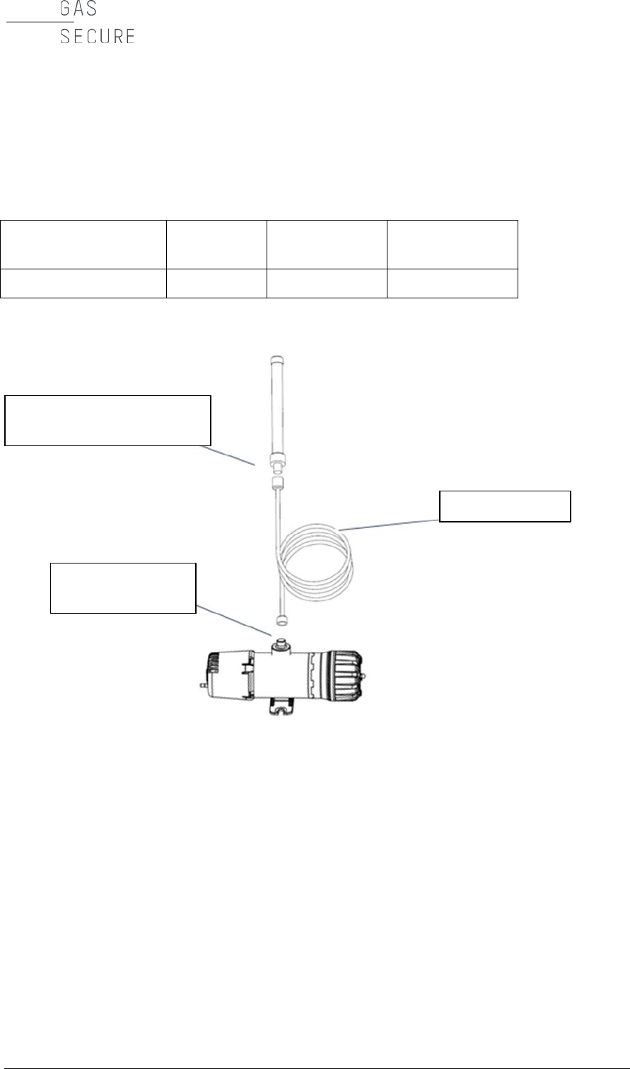
2.5 External antenna (applies only for GS01-EA)
The external antenna is connected to the detector with the antenna cable as
shown in Figure 2-2. The properties of the antenna cable supplied by GasSecure
are shown in Table 2-1. The GS01-EA detector is certified with the coaxial cable
and the omni-directional antenna in Table 5-1. Note that the approved cable
length range is 0-30 m. Do not connect any other antennas than those listed in
Table 5-1.
The external antenna is delivered with a bracket (refer to Reference [10] for
bracket dimensions) and metal bands for easy fitting to a pole (25 – 101 mm) or
External
earth point
GasSecure GS01
Hardware Manual
INSTALLATION
11
similar. Make sure, to the extent possible, that the antenna is mounted vertical
(pointing up or down) and that local radio shadowing is kept at a minimum. Please
read also the safety instructions in Section 6.
Table 2-1: Properties of standard antenna cable for the GS01-EA
Loss/m at 2.5 GHz
[dB]
Diameter
[mm]
Bend radius
[mm]
Weight per m
[g]
0.21
10.3
100
115
Figure 2-2: GS01-EA layout with antenna connections
Omni-directional antenna
N-type connector
Antenna cable
Housing
N-type connector

GasSecure GS01
Hardware Manual
12 CHAPTER 3
3. COMMISSIONING
The GS01 detector(s) is (are) set up in a wireless sensor network with a gateway
and router. The exact commissioning procedure depends on the selected type of
gateway. Therefore, this manual must be used together with the relevant
documentation written for the respective gateway. Some references for such
documentation are provided in Section 9.
On completion of commissioning, the proof test, as described in Section 4.2,
should be executed to validate the correct mapping of the detector output data.
3.1 Communication
The GS01 detector complies with the ISA100 Wireless™ standard for wireless
communication.
Each GS01 detector must be paired with a single gateway, before it can
communicate with the network. The gateway is the interface between the wireless
and plant networks. It marks the transition between communications compliant to
the standard and other communications, and acts as a translator between ISA100
Wireless™ and other protocols (Modbus, PROFINET, etc.).
The pairing process, where the device obtains the appropriate security credentials
and network-specific information, is referred to as provisioning and is explained in
Section 3.7.
3.2 ISA100 Wireless™ standard
ISA100 Wireless™ is a wireless networking technology standard developed by the
International Society of Automation (ISA).
This ISA standard is intended to provide reliable and secure wireless operation for
safety, control, and monitoring applications. This standard defines the protocol
suite, system management, gateway, and security specifications for low-data-rate
wireless connectivity with fixed, portable, and moving field devices supporting very
limited power consumption requirements. The application focus is to address the
performance needs for periodic monitoring and process control where latencies on
the order of 100 ms can be tolerated with optional behaviour for shorter latency.
3.3 ISA100 objects
ISA100.11a defines a communication protocol, with an application layer that
includes a simple but extensible set of input and output objects.
The GS01 detector publishes the measured values and diagnostic information as
ISA100 objects with attributes. It is distinguished between standard attributes and
GS01 device specific attributes.
3.3.1 Standard objects
The GS01 publishes ISA100 standard objects with attributes for process value
and diagnostic status as outlined in Table 3-1 below. The gas measurement value
GasSecure GS01
Hardware Manual
COMMISSIONING
13
is sent as User Application - Analog Input Object with the attribute “Process Value”
(PV). Note that the user may choose which gas configuration to read out by
selecting the corresponding PV object (Methane or Propane) for publication. The
device health information is compiled and sent as User Application Management
Object with the attribute “Diagnostic Status” (DIAG_STATUS).
The concentrator of the gas detector is per default set up to publish the gas
measurement and the diagnostic status. The concentrator can be configured
differently in the gateway interface.
For short detector response time (<5 sec as per GS01 datasheet), the gateway
must be set up with a 2 sec sampling interval (also referred to as publication
period). In the absence of hydrocarbon gas, the detector will not publish on all
available time slots, but per default only publish on every 6th time in order to save
battery power. In the presence of hydrocarbon gas of sufficient concentration
(defined by the internal low alarm limit see Table 8-1), all time slots will be used.
Table 3-1: ISA100 objects
Descriptive
name
Access
-ibility
Octet
no.
Content
Modbus input
registers
Data type
PV
(Methane or
Propane) READ
1
PV_Status
Register N
UINT 16 bit
2
PV_Value (1/4)
Register N+1
32 bit (4 octets)
float, according to
IEEE 754_Float32
3
PV_Value (2/4)
4
PV_Value (3/4)
Register N+2
5
PV_Value (4/4)
DIAG_STATUS READ
1
Diag_Status (1/4)
Register M UINT 16 bit
2
Diag_Status (2/4)
3
Diag_Status (3/4)
Register M+1
4
Diag_Status (4/4)
The content of the PV_Status byte (PV = process value) is explained in Table
10-1 in the Appendix.
The full mapping of the content of the DIAG_STATUS attribute is explained in
Table 10-2 in the Appendix.
Note that a controller is required to display the diagnostic information including
fault or alarm conditions.
Recommendations for which status and diagnostic information to integrate in the
control and maintenance loop are also provided in the Appendix.
3.3.2 GS01 specific objects for safe communication
In addition to the standard objects, the GS01 can be configured to publish and
subscribe to the custom data object “SafeData”. This object is used for safe

GasSecure GS01
Hardware Manual
14 CHAPTER 3
communication. The GS01 uses the PROFIsafe profile over PROFINET as tool for
safe communication. In this setup the GS01 acts as F-Slave, a passive
communication peer able to perform PROFIsafe. Its counterpart is the F-Host, a
data processing unit able to perform PROFIsafe and to trigger the F-Slave for data
exchange. The F-Host must be compliant with the PROFIsafe requirements so
that end-to-end communication through a black channel, defined by the IEC
61508 standard, can be established.
Please refer to the GS01 safety manual [RD 9] for further information on how to
set up safe communication with PROFIsafe. For applications without PROFIsafe
the “SafeData” object shall be disregarded.
3.4 GS01 data format details
The GS01 data objects can be mapped into 16 bit Modbus input registers.
The “PV” object (cf. Section 3.3.1) normally populates three registers; the
PV_Status byte populates the last 8 bits of the first register and the 32 bit float
number populates the following two registers.
The “UAPMO.DIAG_STATUS” object (cf. Section 3.3.1) is normally mapped into
two 16 bit registers. Some gateways will also add a status byte into the preceding
register. This status byte may be ignored, because its information is already
contained in the PV_status byte.
The procedure for Modbus register mapping depends on the specific gateway,
please consult the respective gateway manual on how to achieve this mapping.
GasSecure can assist with advice if needed.
3.5 Modification of LEL
Regionally different conversion factors may apply for the display of measured
concentrations in percent of the lower explosion limit (LEL). The GasSecure GS01
gas detector allows you to select one of two LEL categories, which basically
correspond with common explosion limits in the USA (NIOSH Pocket Guide to
Chemical Hazards4) and Europe IEC 60079-20), cf. Table 3-2. The factory default
setting is LEL according to IEC. The LEL category may be changed with the GS01
Configurator tool as part of device provisioning as explained in Section 3.7.
Note that this feature is supported for GS01 firmware version ≥ 3.3.
Table 3-2: LEL values in [% vol] according to IEC and NIOSH
LEL values [% vol] for
IEC (factory default)
NIOSH
Methane
4.4
5.0
Propane
1.7
2.1
4 See http://www.cdc.gov/niosh/npg/
GasSecure GS01
Hardware Manual
COMMISSIONING
15
3.6 Communication monitoring
The PV_Status byte (see Table 3-1) can be used for monitoring the
communication status and the data integrity. See Table 10-1 in the Appendix for
all details. With no error present (e.g. beam block or critical low power) and the
detector communicating with the gateway, the status byte will be decimal value 64
or higher; please refer to Table 3-3 below for the three main classes of data
integrity.
The status byte is updated by the gateway if the communication with the detector
is lost. The time from reception of the last packet and until the status byte is
updated to flag “lost communication” is defined via the stale limit parameter.
Please consult the gateway manual for information about setting this stale limit.
GasSecure’s recommendation is a sampling interval of 2 sec (see Section 3.3.1)
together with a stale limit of 30 times, so that “lost communication” is flagged after
maximum 60 sec. Under no circumstances the stale limit must be set to less than
6, because this would disable communication between detector and gateway.
Note that the timeout, as defined by the stale limit, can be checked by removing
the battery and monitoring the time until the PV_Status byte is updated.
Table 3-3: PV Gas measurement data integrity
Data integrity
Octet decimal
number
Explanation and actions
Bad
< 64
No communication or hardware failure.
Check communication. Contact GasSecure if
this failure persists.
Uncertain
64 to 127
The integrity of the data is uncertain. As
example, the sensor range or
temperature
range may be exceeded.
Good
= 128
Normal operation. The detector is providing
reliable gas measurements.
3.7 GS01 detector provisioning
All GS01 detectors have to be provisioned so that they will join the correct
network. Provisioning the GS01 requires the following:
• The GS01 serial adapter together with the GS01 Configurator software
(both accessories from GasSecure)
• FTDI virtual comport driver for the GS01 serial adapter
• The network (or subnet) ID of the gateway or backbone router
• For Yokogawa gateway only: A Capability File (CF) for the GS01 device.

GasSecure GS01
Hardware Manual
16 CHAPTER 3
Software tools, drivers, and files (e.g. CF) are available for download at
http://tools.gassecure.com.
This procedure can be carried out with an unprovisioned GS01 or with a GS01
that earlier has been provisioned to another gateway.
3.7.1 Yokogawa gateways
a) Connect the GS01 to a PC with the GS01 Configurator installed using the
GS01 serial adapter.
b) Run the GS01 Configurator and select the correct COM port. Keep the
default mode “Provision one GS01 device”. Press the “Connect” button and
verify that the device information is displayed, cf. Figure 3-1. Press the
“Read version info” button if the device information does not show
automatically. Press the “Read” button so that the current provisioning
status of the device is displayed.
c) Enter the device tag and the required network ID in decimal format, cf.
Figure 3-1.
d) For the join key there are two options.
i. Specific (user-defined) join key: Type a 32-bit hexadecimal number
in the “join key” field.
ii. Generate a random join key: Press the “Generate random join key”
button.
e) Check and set the LEL category to either IEC or NIOSH as defined in Table
3-2.
f) Check the destination folder for the ypif file and change it by pressing the
“...” button if necessary. Press the “Generate ypif file” button. This file must
be uploaded to the gateway (explained in reference [RD 4]) to enable
communication. Press the “Apply” button (do not make any changes to the
provisioning input data between pressing the two buttons!).
g) Close and exit the GS01 Configurator and disconnect the GS01 detector
from the PC.
h) Power up the GS01 by inserting the battery pack.
i) The GS01 device should join the network within 5-20 minutes, if it is within
radio distance to the gateway and the gateway is set up properly (refer to
reference [RD 4]). If the gateway is out of radio range, the GS01 device will
try to connect for a period of 60 min and then enter a power-saving mode.
In this mode it will try to connect for a 5 min period once per hour.
GasSecure GS01
Hardware Manual
COMMISSIONING
17
Figure 3-1: GS01 Configurator
3.7.2 Nivis gateway VR800/900
a) Connect the GS01 to a PC with the GS01 Configurator tool installed using
the GS01 serial adapter.
b) Run the GS01 Configurator and select the correct COM port. Keep the
default mode “Provision one GS01 device”. Press the “Connect” button and
verify that the device information is displayed, cf. Figure 3-1. Press the
“Read version info” button if the device information does not show
automatically. Press the “Read” button so that the current provisioning
status of the device is displayed as well.
c) Enter the device tag and the required network ID in decimal format, cf.
Figure 3-1.
d) For the join key there are two options.
i. Specific (user-defined) join key: Type a 32-bit hexadecimal number
in the “join key” field.
ii. Generate a random join key: Select “randomize join key”. Press the
“Generate random join key” button.
Note down the join key. It is needed for configuring the Nivis gateway.
e) Check and set the LEL category to either IEC or NIOSH as defined in Table
3-2.
f) Press the “Apply” button.
g) Close and exit the GS01 Configurator and disconnect the GS01 detector
from the PC.

GasSecure GS01
Hardware Manual
18 CHAPTER 3
h) Power up the GS01 by inserting the battery pack.
i) The GS01 device should join the network within 5-20 minutes, if it is within
radio distance to the gateway and the gateway is set up properly. If the
gateway is out of radio range, the GS01 device will try to connect for a
period of 60 min and then enter a power-saving mode. In this mode it will
try to connect for a 5 min period once per hour.
3.7.3 Over the air (OTA) provisioning
a) Connect the GS01 to a PC with the GS01 Configurator installed using the
GS01 serial adapter.
b) Run the GS01 Configurator and select the correct COM port. Keep the
default mode “Provision one GS01 device”. Press the “Connect” button and
verify that the device information is displayed, cf. Figure 3-1. Press the
“Read version info” button if the device information does not show
automatically. Press the “Read” button so that the current provisioning
status of the device is displayed.
c) Press the “Reset radio to factory defaults” button.
d) Close and exit the GS01 Configurator and disconnect the GS01 detector
from the PC.
e) Power up the GS01 by inserting the battery pack.
f) The GS01 can now be provisioned over the air (OTA) using either special
field tools or the field wireless access points. Refer to references [RD3],
[RD6] or [RD 8] for possible solutions from different vendors.
3.8 Modifications to an existing network
1. Add a detector
Provision the GS01 as described in Section 3.7.
Mount the GS01 with battery.
Re-configure the gateway to accommodate the additional detector(s) (cf.
Section 9 for gateway relevant documentation).
2. Replace a detector
Power down the GS01 in question by removing its battery.
Provision the replacement GS01 by following all steps in Section 3.7.
Mount the replacement GS01 with battery.
Re-configure the gateway to accommodate the replacement detector(s) (cf.
Section 9 for gateway relevant documentation).
3. Remove a detector
Power down the GS01 in question by removing its battery pack.
Optional: Re-configure the gateway in order to remove the detector from
the list of publishers (cf. Section 9 for gateway relevant documentation).

GasSecure GS01
Hardware Manual
COMMISSIONING
19
3.9 Visual and functional check
The following activities are recommended before putting into operation the GS01
detector:
• The axis of the detector shall be horizontal.
• Verify the correct orientation of the weather cap (cf. Figure 2-1).
• Check that all bolts and screws are securely tightened.
• Carry out a validation as described in Section 4.2.
• It is moreover recommended to read the procedures described in IEC
60079-29-2 for reference.

GasSecure GS01
Hardware Manual
20 CHAPTER 4
4. OPERATION
The GS01 has no user adjustable parts. Do not open the instrument. Opening the
GS01 detector voids the warranty issued by the manufacturer.
4.1 Normal operation
After provisioning the GS01 detector with an ISA100 Wireless™ gateway, it will
perform the following tasks:
• Measure gas concentration
• Publish gas concentration to the gateway
• Publish other diagnostic information to the gateway
4.2 Proof test (Validation)
Referring to Section 3.5, note that the GS01 is set to detect gas on a % LEL scale
either according to IEC60079-20 or to NIOSH.
Although no re-calibration of the GS01 is necessary, it is recommended to check
the response of the detector at least every second year by applying pressurized
test gas.
The weather cap is designed for validation, as it includes a 6 mm diameter tube
fitting for efficiently filling the GS01 measuring cell with a test gas mixture. Note
however that the test gas will leak out during testing and leakage will depend on
the wind speed. Therefore, the measured gas concentration is normally lower than
stated on the test gas cylinder. It is not recommended to carry out validation in
stronger wind, or alternatively the weather cap has to be covered on the outside
for example by applying tape to the openings.
The function of the detector is positively validated as long as it responds to the
test gas.
Please refer to Table 4-1 for the recommended gas mixtures and expected
instrument readings. Apply the test gas through a 6 mm tube from a gas cylinder
with pressure regulator. It is recommended to adjust the flow to at least 5 L/min.

GasSecure GS01
Hardware Manual
MAINTENANCE
21
Table 4-1: Recommended gas concentrations for validation
Detector version and
LEL category
Recommended test gas
Expected reading
Methane, IEC
Methane 2.2 % vol in
synthetic air
Or alt. 2.5 % vol in synth. air
50 % LEL
57 % LEL
Propane, IEC
Propane 0.42 % vol in
synthetic air
Or alt 1.0 % vol in synth. air
25 % LEL
59 % LEL
Methane, NIOSH
Methane 2.5 % vol in
synthetic air
50 % LEL
Propane, NIOSH
Propane 0.42 % vol in
synthetic air
Or alt 1.0 % vol in synth. air
20 % LEL
48 % LEL

GasSecure GS01
Hardware Manual
22 CHAPTER 5
5. MAINTENANCE
The GS01 detector is designed for minimum maintenance.
The instrument does not have user adjustable parts. Do not attempt to open or
disassemble the instrument. This can compromise safety and performance.
Opening the GS01 voids the warranty issued by the manufacturer. All repairs have
to be done by the manufacturer or by an authorised dealer.
5.1 Routine maintenance
For best performance it is recommended to routinely carry out the following steps:
• Clean the window and mirror when necessary (see Section 5.3 below). The
optical transmission of the infrared sensor maybe monitored with the
DIAG_STATUS attribute explained in Table 5-2 and Table 10-2.
• Check the weather cap regularly to make sure it is not clogged (see Section
5.3 below).
• Check battery status regularly. Replace low batteries in due time (see Section
5.4 below). The battery status maybe monitored with the DIAG_STATUS
attribute explained in Table 5-2 and Table 10-2.
• Check the detector response at least every second year (see Section 4.2).
5.2 Spare parts and accessories
Table 5-1: Important spare parts and accessories for the GS01
Description
GasSecure p/n
Dräger p/n
Battery pack
10055
AL20712
O-ring for battery compartment
30410
--
Weather cap
10078
AL20709
Battery cap
10022
AL20708
Sunshade
10123
AL20711
GS01 serial adapter
10156
AL20710
6 dBi antenna (only for GS01-EA)
10204
AL20718
Standard antenna cable for GS01-EA, 5m
10200-5
AL20719

GasSecure GS01
Hardware Manual
MAINTENANCE
23
5.3 Cleaning
In the event of low or blocked optical transmission of the IR sensor, the optical
window and external mirror (see Figure 1-4 for their exact location) should be
cleaned.
Please proceed as follows:
• Remove battery to avoid unwanted alarms while cleaning.
• Use soft tissue or a cotton swab and a lens cleaning fluid based on pure
water and isopropyl alcohol (IPA) and/or other alcohols.
• Flush or wipe with pure water afterwards, and dry off with a soft dry tissue.
• Reinstall the battery.
• Note that gas alarms are likely to occur during and shortly after cleaning
due to the detector’s sensitivity to alcohol. This is avoided by removing the
battery while cleaning.
• Other cleaning agents are not recommended, but if lens cleaning fluid or
IPA is not available, a diluted dishwasher detergent may be used if followed
by a thorough flushing with pure water. Dry off any remaining water
droplets.
The inside of the ultrasonic sensor does not need cleaning. If the perforated sheet
is clogged with dirt, clean compressed air may be used for removal.
If the detector is installed in an area where the weather cap may become clogged
(for instance by insects, leaves, ice or snow), it is recommended that this cap is
inspected regularly to make sure that air flows freely through the openings.
5.4 Battery pack
Note that the GS01 may only be operated with the GasSecure battery pack (p/n
10055).
5.4.1 Battery pack replacement
The battery pack is installed or replaced simply by twisting off the battery cap,
pulling out the old pack, pushing the new one in place, and putting back the cap.
Make sure that the O-ring fits and tightens on the entire circumference of the
battery compartment. The battery pack will only fit one way, so that correct polarity
is ensured. After inserting the battery pack, it may take up to 15 minutes before
the detector is transmitting data, depending on how the network is set up.
5.4.2 Battery cell replacement
The battery cells in the battery pack can be replaced. Assemble the battery pack
as described below.
Caution!
Only use battery packs that
GasSecure GS01
Hardware Manual
24 CHAPTER 5
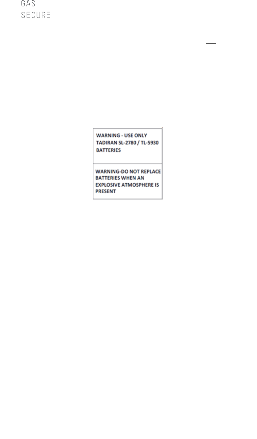
• are designed for battery cell replacement. They will contain the label
depicted in Figure 5-1. Battery packs without this label may not be opened.
• are clean and free of contamination.
• are visually intact (particularly no damage around the screw holes).
• have no visible corrosion on the terminal contacts.
Use only the following approved battery cells in the battery pack:
• Tadiran model no. SL-2780/S
• Tadiran model no. TL-5930/S
Battery cell replacement and opening the battery pack must take place in a safe
area, where a potential explosive atmosphere is not present.
Figure 5-1: Battery pack warning label
Replacement:
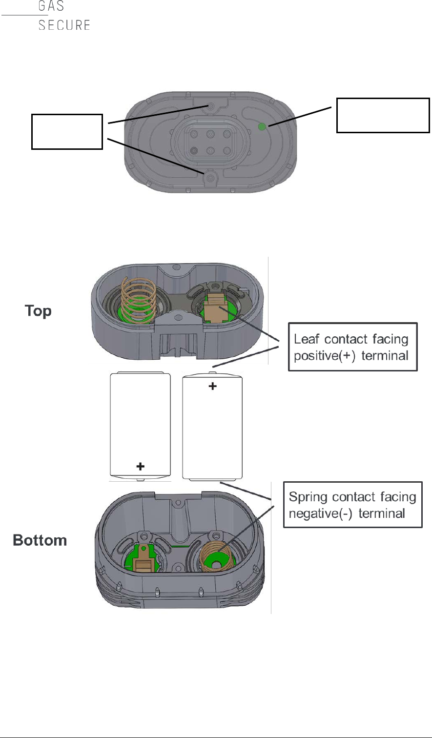
• Loosen the two battery pack mounting screws (Torx T10), see Figure 5-2.
Note that the spring force is high, have therefore a firm grip around the
pack while unscrewing.
• Remove both used cells and dispose according to the battery cell safety
datasheet (see Section 5.4.3 for more information). Do not disassemble the
battery pack any further.
• Verify that new cells are of the correct type (see above). Be sure to replace
both battery cells at the same time and only use fresh (previously unused)
cells.
• Place both battery cells in the battery pack, leaf contact facing the positive
(+) terminal and spring contact facing the negative (-) terminal, cf. Figure 5-
3.
• Assemble lid and bottom of the pack by tightening the two screws (Torx
T10) with a torque of approximately 0.7 Nm. Have a firm grip around the
pack until the screws are tight.
• Press the button on the pack, see Figure 5-2 (the button is located behind a
hole in the pack and accessible with the tip of a pen). This will indicate to
the gas detector that fresh batteries are in place and re-set the charge
counter. Note that only gas detectors with firmware 3.0 or later will
recognize this button operation. Please contact GasSecure should the
detector in question contain an older firmware version or should you be
uncertain about the firmware of this detector.
GasSecure GS01
Hardware Manual
MAINTENANCE
25
Figure 5-2: Battery pack bottom view
Figure 5-3: Battery pack top and bottom
with leaf and spring contacts facing the battery positive (+) and negative (-)
terminal, respectively.
Mounting
screws
Re-set button
location
GasSecure GS01
Hardware Manual
26 CHAPTER 5
5.4.3 Handling battery packs and cells
The battery pack comprises two primary lithium thionyl chloride battery cells.
Under normal conditions, the battery materials are self-contained and are not
reactive as long as the battery cell and pack integrity are maintained. Care should
be taken to prevent thermal, electrical or mechanical damage. Protect the
electrode of the battery cells to avoid short circuits. Shorted battery cells may leak
fluid and produce excessive heat. Batteries should be stored in a clean and dry
area. For maximum battery life, storage temperature should not exceed 25°C.
Warning. Fire, explosion, and severe burn hazard!
• Never recharge a battery pack or cell.
• Do not disassemble the battery cells.
• Do not incinerate, heat above 100°C, or expose battery packs and cells to
water.
Please consult the battery cell material safety datasheet for further information.
When carried in potentially hazardous areas, the battery pack shall be kept inside
an antistatic bag to avoid static charge build-up on the battery pack surface.
Transport
Batteries used for the GS01 detector contain lithium. Transport of primary lithium
batteries is regulated by the U.S. Department of Transportation, the International
Air Transport Association (IATA), the International Civil Aviation Organization
(ICAO), and the European Ground Transportation of Dangerous Goods (ARD). It
is the responsibility of the shipper to ensure compliance with these or any other
local requirements. Consult current regulations and requirements before shipping.
Disposal
The battery pack is considered as hazardous waste. Please dispose of it
according to laws and regulations for such waste. In the European Union directive
2006/66/EC must be respected.
5.5 Storage
The battery pack shall be disconnected when the detector is stored away or not in
service for longer periods. The same applies when the gateway is unavailable
(powered down or out of radio range). This is to avoid that the batteries are
depleted. The GS01 power consumption can increase to approximately 3 times
the normal average consumption when the gateway is not accessible to the device
for the above-mentioned reasons.
5.6 Troubleshooting
Essential instrument status information is provided through the standard ISA100
Wireless object “DIAG_STATUS” (cf. Section 3.3.1). Please refer to the Appendix
for a recommended implementation of the GS01 status and diagnostic

GasSecure GS01
Hardware Manual
MAINTENANCE
27
information. The “Diag_Status” attribute provides the information as outlined in
Table 5-2.
If multiple warnings or errors occur, always clear battery warning or error first by
replacing the battery pack (cf. Section 5.4.1).
For failures (mode F) not explained in Table 5-2, please clean window and mirror
(cf. Section 5.3). If the failure persists, contact GasSecure.
Table 5-2: Status messages retrieved from the Diag_Status attribute
Instrument
mode
(cf. Table 10-2)
DIAG_STATUS
bit set
(cf. Table 10-2)
Explanation and actions
M
19
Low battery.
The battery must be replaced.
F and M
20
Empty battery.
Replace battery immediately (see Section 5.4).
M
7
Attenuated optical beam (low optical
transmission).
The instrument detects low light transmission
and infrared signal strength most probably due
to dirty optics. Clean the window and
mirror if
necessary (cf. Section 5.3). The
status
message will clear within 10 minutes.
F and M
8
Beam block (optical beam fault).
The signal is so weak that the gas
concentration cannot be calc
ulated with
sufficient accuracy,
or the beam intensity is
changing rapidly.
Check for dirty optics and clean the window
and mirror (cf. Section 5.3) if necessary.
O
22
The system temperature is outside the
specified operating range. For repeated high
temperature warnings the use of a sunshade
should be considered.
F, O, and M
22 and 8
Process value under-range.
Clean the window and mirror (cf. Section 5.3
).
If the error persists, contact GasSecure.
5.7 Contact GasSecure for support
You will find our contact information and an updated list of our representatives on
our homepage
www.gassecure.com

GasSecure GS01
Hardware Manual
28 CHAPTER 5
When contacting the factory for support, the following information should be
provided: - The instrument serial number
- Description of the problem
- The type of gateway used for wireless communication

GasSecure GS01
Hardware Manual
SAFETY INSTRUCTIONS
29
6. SAFETY INSTRUCTIONS
The GS01 detector from GasSecure is certified for and intended for use in
potentially hazardous areas. Install and use the GS01 detector in accordance with
the appropriate local or national regulations.
Test gases (for validation) may be toxic and/or combustible. Refer to the Material
Safety Sheets for appropriate warnings.
The gas detector shall be installed and operated by trained and qualified
personnel.
Warning – the GS01-EA antenna is a potential electrostatic charging hazard.
The GS01-EA external antenna surface is highly resistive. Avoid electrostatic
charge build-up. If necessary, only clean the unit with a damp cloth. Do not rub the
antenna with non-conductive materials.
Remember to secure the GS01 detector when working at heights.
Do not open the instrument. All warranties void if opened. There are no user
serviceable parts or settings inside. The manufacturer or its authorised dealers
shall do any repair.
In order to maintain an FM Approved system, the apparatus to which this
instrument is connected, must also be Approved by FM Approvals.
The GS01 and GS01-EA gas detectors comply with EN 60079-29-1 when
connected to a control unit that also has been evaluated to EN 60079-29-1.

GasSecure GS01
Hardware Manual
30 CHAPTER 7
7. CERTIFICATIONS AND STANDARDS
7.1 Standards
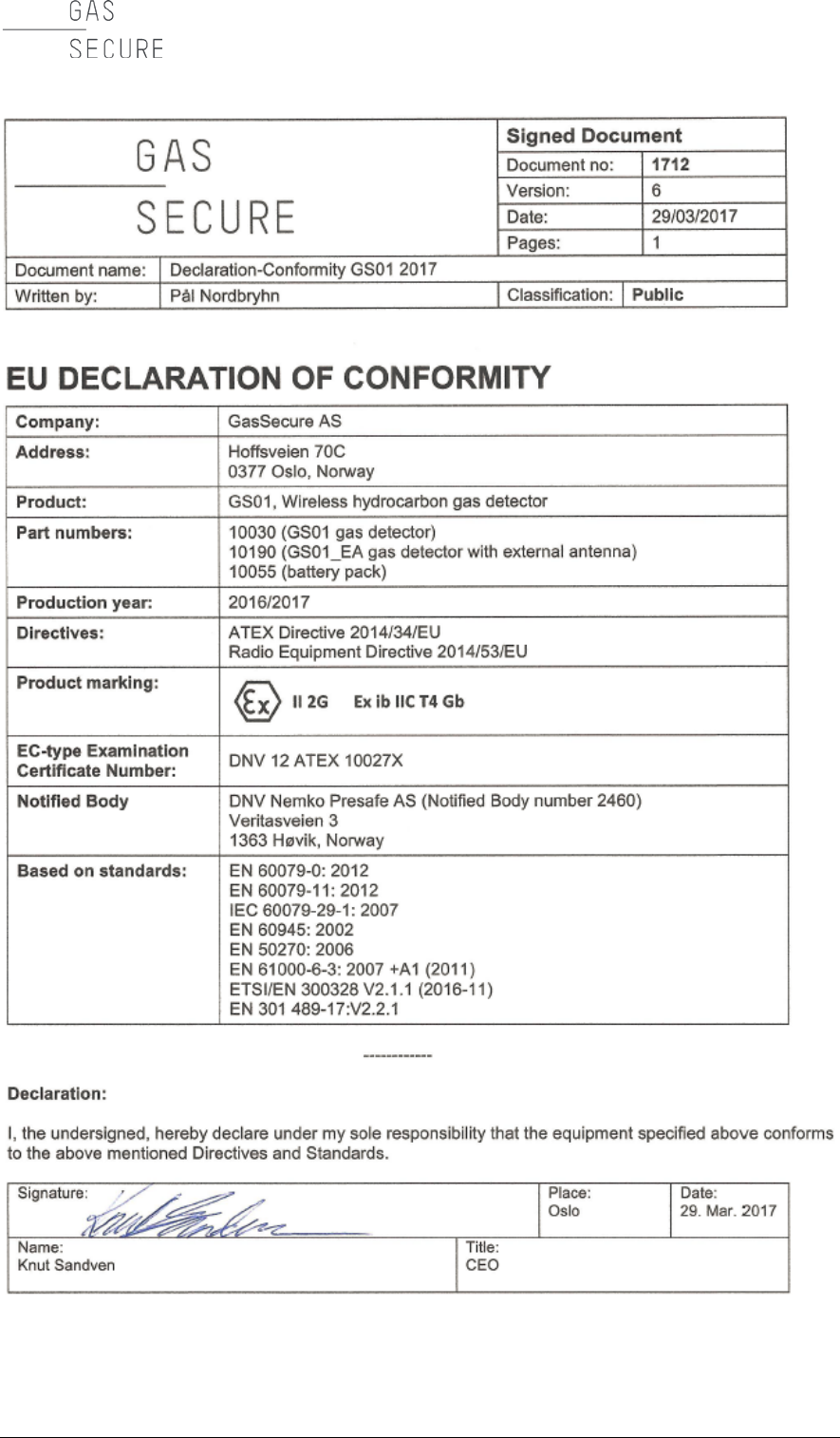
The GS01 has been certified according to the ATEX Directive 2014/34/EU and is
compliant with Radio Equipment Directive (RED) 2014/53/EU and the standards
listed below. See also EU Declaration of Conformity in the Appendix.
Table 7-1: List of applicable standards for the GS01
Standard
Issue date
Title
EN 60079-0
2012
Electrical apparatus for potentially explosive
atmospheres. General requirements.
EN 60079-11
2012
Electrical apparatus for potentially explosive
atmospheres. Intrinsic safety “i”.
IEC 60079-0
2011
Explosive atmospheres – Part 0: Equipment.
General requirements.
IEC 60079-11
2011
Equipment protection by intrinsic safety "i".
EN 60079-29-1
2007
Gas detectors – Performance requirements
of detectors for flammable gases.
EN 60945
2002
Maritime navigation and radio-
communication equipment and systems.
General requirements.
Methods of testing
and required test results.
EN 50270
2006
Electromagnetic compatibility. Electrical
apparatus for the detection and measure-
ment of combustible gases, toxic gases
or
oxygen.
EN 61000-6-3: 2007
+A1 (2011)
2011
Electromagnetic compatibility (EMC) - Part 6-
3: Generic standards. Emission standard for
residential, commercial and light-
industrial
environments.
ETSI/EN 300 328
V2.1.1
2016-11
Electromagnetic compatibility and Radio
spectrum Matters (ERM).
IEC 61508 Ed. 2.0
2010-04
Functional safety of electrical, electronic,
programmable electronic safety-related
systems
CFR title 47 Part 15C
Code of federal regulations, telecom-
munications, radio frequency devices,
intentional radiators
GasSecure GS01
Hardware Manual
CERTIFICATIONS
31
7.2 Regulatory compliance of radio for GS01
7.2.1 Radio equipment directive (RED)
The GS01 and GS01-EA wireless gas detector complies with the essential
requirements and provisions of RE Directive 2014/53/EU.
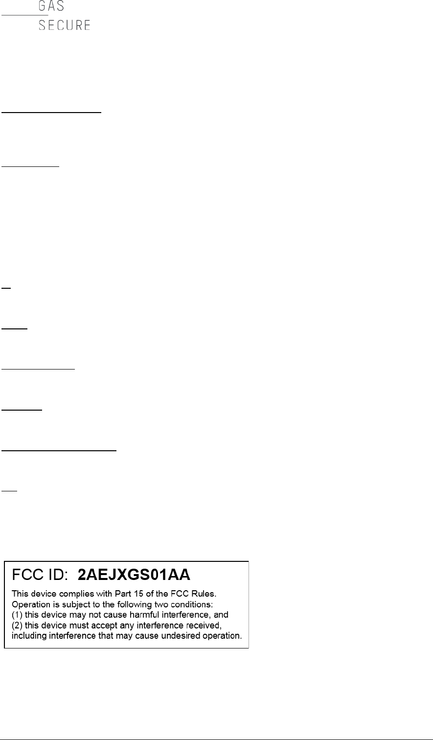
7.2.2 FCC compliance
The GS01 and GS01-EA device complies with Part 15 of the FCC Rules.
Operation is subject to the following two conditions: (1) this device may not cause
harmful interference, and (2) this device must accept any interference received,
including interference that may cause undesired operation.
Changes or modifications to the equipment not expressly approved by the party
responsible for compliance could void the user's authority to operate the
equipment.
This equipment has been tested and found to comply with the limits for a Class A
digital device, pursuant to Part 15 of the FCC Rules. These limits are designed to
provide reasonable protection against harmful interference when the equipment is
operated in a commercial environment. This equipment generates, uses, and can
radiate radio frequency energy and, if not installed and used in accordance with
the instruction manual, may cause harmful interference to radio communications.
Operation of this equipment in a residential area is likely to cause harmful
interference in which case the user will be required to correct the interference at
his own expense.
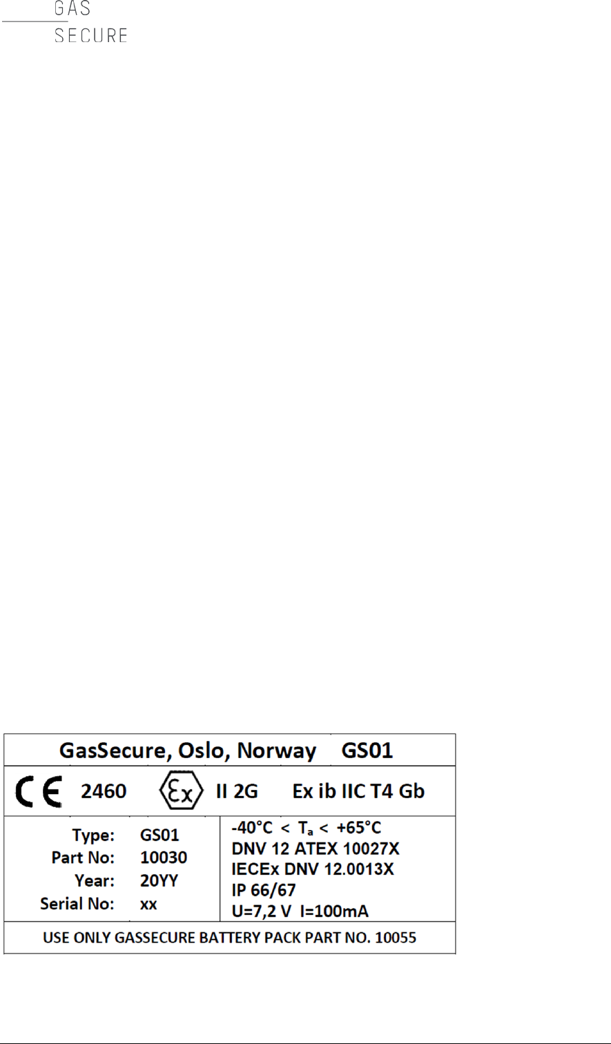
7.3 Marking
The GS01 and GS01-EA detectors are marked with product identification plates
as shown in Figure 7-1 through Figure 7-4. The detectors are in addition marked
with a label for FCC compliance (cf. Figure 7-5). The marking is explained in detail
under the figures.
The antenna delivered with the GS01-EA is also marked with an identification
label, cf. Figure 7-7:
Figure 7-1: GS01 product identification plate
GasSecure GS01
Hardware Manual
32 CHAPTER 7
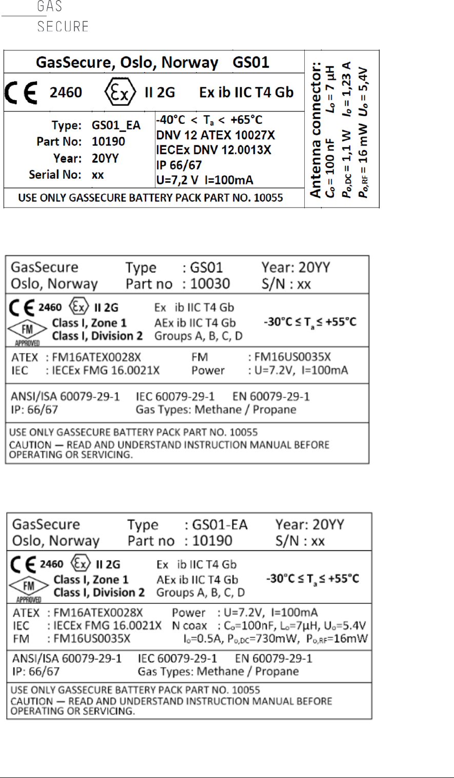
Figure 7-2: GS01-EA product identification plate
Figure 7-3: GS01 product identification plate – FM approved
Figure 7-4: GS01-EA product identification plate – FM approved
GasSecure GS01
Hardware Manual
CERTIFICATIONS
33
The instrument marking string II 2G Ex ib IIC T4 Gb means the following:
Equipment group II
Electrical apparatus for places with an explosive gas atmosphere other than mines
susceptible to firedamp.
Category 2
Equipment designed to be capable of functioning in conformity with the operating
parameters established by the manufacturer and of ensuring a high level of
protection. Equipment in this category is intended for use in areas in which
explosive atmospheres caused by vapours, gases, mists, or air/dust mixtures are
likely to occur. The means of protection relating to equipment in this category
ensure the requisite level of protection even on the event of frequently occurring
disturbances or equipment faults, which normally have to be taken into account.
G
The instrument is approved for use in gas, vapour, and mist atmospheres.
Ex ib
The method of protection is “intrinsic safety”.
Gas group IIC
Not restricted to certain gases.
IP66/67
Ingress protection level (as defined in EN 60529).
Temperature class T4
The maximum surface temperature of components will not exceed 135 oC.
Gb
Equipment protection level “Gb”: Equipment for explosive gas atmospheres,
having a "high" level of protection, which is not a source of ignition in normal
operation or during expected malfunctions.
Figure 7-5: FCC compliance label
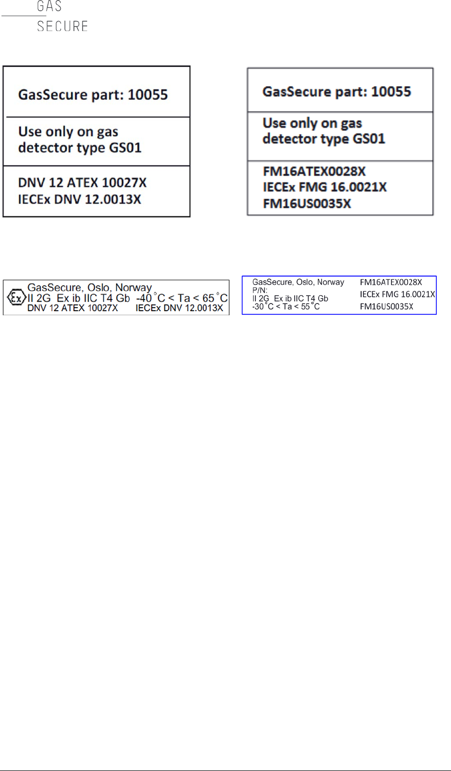
The GasSecure battery pack is marked with an identification label as shown in
Figure 7-6 below.
GasSecure GS01
Hardware Manual
34 CHAPTER 7
Figure 7-6: Battery pack identification label (FM approved version to the right)
Figure 7-7: Antenna identification label (FM approved version to the right)

GasSecure GS01
Hardware Manual
TECHNICAL DATA
35
8. TECHNICAL DATA
8.1 Performance Characteristics
Table 8-1: Performance characteristics for the GS01
Detector Version
GS01-01A
GS01-02A
Calibration Gas
Methane
Propane
Measuring Range5
0 – 100% LEL
0-80% LEL
Internal Low Alarm Limit6
10% LEL
Initialization time
60 s
Response
time
Default
5 s > 10% LEL
5 s > 10% LEL
Maximum for low
concentrations7
60 s < 10%LEL
60 s < 10%LEL
Accuracy8
± 3% LEL or
± 10% of
reading,
whichever is
greater
± 2% LEL or
± 10% of reading
whichever is
greater. ± 20% of
reading > 80% LEL.
Dead band
± 4% LEL
± 3% LEL
Battery life time9
Up to 2 years
8.1.1 Response time for other hydrocarbon gases and mixtures
Table 8-1 states response times for different concentrations of methane and
propane in air. In order to achieve the default response time of 5 seconds, the
speed of sound in the gas or gas mixture must be sufficiently different from this
speed in air to be detected by the ultrasonic sensor (please refer to Section 1.1 for
a brief introduction to the GS01 dual sensor concept). For methane and propane
this occurs for concentrations above 10% LEL.
Note that, with hydrocarbon gas mixtures of light (e.g. methane) and heavy (e.g.
propane) gas, the ultrasonic sensor must respond to a mixture of gases, with a
speed of sound that could be close to that in air. Therefore, larger concentrations
are required for mixtures of methane and propane to consistently achieve the 5
second response time. For other hydrocarbons, there will be differing
concentration limits that will be required to achieve the 5 second response. Please
contact GasSecure for advice of the concentration limits for other gases or gas
mixtures. Note that the response time for low concentrations of hydrocarbon gas is
never more than 60 seconds.
5 LEL limits, please refer to Table 3-2
6 Refer to Section 3.3.1 for further explanation
7 Due to the limited sensitivity of the ultrasonic sensor
8 Refers to operating temperature range.
9 Assuming I/O device role and non-condensing environment.
GasSecure GS01
Hardware Manual
36 CHAPTER 8
8.2 Cross sensitivities
The GS01 is sensitive to many hydrocarbon gases, and does not distinguish one
from another. In the tables below cross sensitivities to important hydrocarbon
gases are presented. Please note that these are modelled estimates and shall be
used as an indication only. Please contact GasSecure for cross sensitivity
estimates for other gases than those listed below.
The tables are read as follows: The instrument reading is looked up in the first
column. The estimated actual concentration is found in the same row in the
column for the gas to be measured.
Example from Table 8-3: If a methane detector is exposed to ethanol and a value
of 40 %LEL is read, the actual concentration of ethanol is approximately 15 %LEL.
8.2.1 GS01 detector with LEL according to IEC
All values are in % LEL. LEL values as provided in Table 8-2.
Table 8-2: LEL values in [% vol] according to IEC60079-20.
Methane Propane
Methanol
Ethanol
Ethylene
N-butane
Hexane
Styrene
Benzene
4.4
1.7
6.0
3.1
2.3
1.4
1.0
1.0
1.2
Table 8-3: Cross sensitivities for a GS01 Methane detector.
Reading Propane Methanol Ethanol Ethylene N-butane Hexane Styrene Benzene
10
5
4
6
34
6
7
16
28
20
9
7
10
54
10
11
25
46
30
11
8
12
69
12
14
32
59
40
14
10
15
81
15
17
38
71
50
15
11
17
91
17
19
43
81
75
19
14
21
113
21
24
53
103
100
23
16
24
131
25
28
61
122
Table 8-4: Cross sensitivities for a GS01 Propane detector.
Reading Methane Methanol Ethanol Ethylene N-butane Hexane Styrene Benzene
10
24
7
11
61
11
12
28
52
20
79
14
21
116
22
25
54
106
30
159
21
31
167
33
38
77
164
40
200
27
40
>200
44
52
98
>200
50
>200
32
49
>200
55
67
117
>200
75
>200
43
69
>200
83
111
155
>200
100
>200
52
86
>200
113
167
184
>200
8.2.2 GS01 detector with LEL according to NIOSH
All values are in % LEL. LEL values as provided in Table 8-5.
Table 8-5: LEL values in [% vol] according to NIOSH.
Methane Propane
Methanol
Ethanol
Ethylene
N-butane
Hexane
Styrene
Benzene
5.0
2.1
6.0
3.3
2.7
1.6
1.1
0.9
1.2

GasSecure GS01
Hardware Manual
TECHNICAL DATA
37
Table 8-6: Cross sensitivities for a GS01 Methane detector.
Reading Propane Methanol Ethanol Ethylene N-butane Hexane Styrene Benzene
10
5
5
6
31
6
7
19
31
20
8
7
10
50
9
11
30
50
30
10
9
13
63
12
14
38
64
40
12
11
15
74
14
16
45
76
50
13
12
17
83
16
19
51
87
75
17
15
21
103
20
23
62
111
100
20
17
24
119
23
28
72
132
Table 8-7: Cross sensitivities for a GS01 Propane detector.
Reading Methane Methanol Ethanol Ethylene N-butane Hexane Styrene Benzene
10
30
9
13
63
12
14
39
64
20
101
17
24
120
23
28
73
133
30
197
25
35
170
35
43
102
>200
40
>200
32
46
>200
47
60
128
>200
50
>200
38
55
>200
60
78
151
>200
75
>200
50
77
>200
91
135
196
>200
100
>200
60
95
>200
123
>200
>200
>200

GasSecure GS01
Hardware Manual
38 CHAPTER 9
9. REFERENCES
[RD 1]
Nivis ISA100.11a R2.7 Monitoring Control System User
Guide Version: 1.2, Date: March 30, 2012
[RD 2]
Nivis VersaRouter 900 Hardware User Guide
(VR800 Internal Hardware Rev. C)
Version 1.4, Date: Mar. 18, 2010
[RD 3]
Yokogawa YFGW410 Field Wireless Management Station
user’s manual, IM 01W02D01-01EN
[RD 4]
Yokogawa YFGW410 Field Wireless Management Station
Startup Guide, TI 01W01A56-01EN
[RD 5]
Yokogawa YFGW510 Field Wireless Access Point user’s
manual, IM 01W02E01-01EN
[RD 6]
Honeywell Wireless Device Manager User's Guide, Release
220, OWDOC-X254-en-220A, October 2013
[RD 7]
Honeywell Field Device Access Point User's Guide, Release
220, OWDOC-X256-en-220A, October 2013
[RD 8]
Nivis ISA100.11a Field Tool User Manual, Version 2.1, Date:
October 17, 2013
[RD 9]
GasSecure GS01 wireless infrared hydrocarbon gas detector,
Safety Manual, document ID 21440
[RD 10]
HUBER+SUHNER data sheet for Sencity OMNI-M Antenna:
1324.170114
GasSecure GS01
Hardware Manual
APPENDIX
39
10. APPENDIX
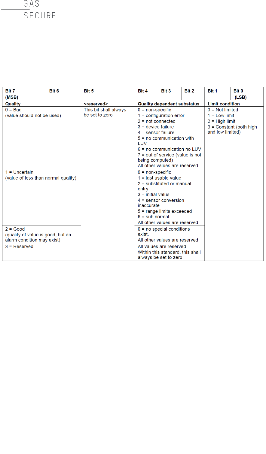
Table 10-1: PV_Status byte description according to ISA100 Wireless™ standard
Table 10-2: Content of the DIAG_STATUS attribute
(Next page)
Note also
F: Failure
C: Function check
O: Out of specification
M: Maintenance required
According to the NAMUR NE107 categorization.
GasSecure specific acronyms as used in GasSecure software tools are added in a
separate column.

GasSecure GS01
Hardware Manual
40 CHAPTER 10
Bit DIAG_STATUS
Not supported if
bit = 0
NAMUR NE107
GasSecure
acronym
31 F: Failure Status F
30 C: Function check C
29 O: Out of specification status O
28 M: Maintenance required status M
27 Faults in electronics FFIE
26 Faults in sensor or actuator element FFSA
25 Installation, calibration problem CICP
24 Out of service COOS
23 Outside sensor limits 0 O
22 Environmental conditions, out of device spec. OENC
21 Fault Prediction: Maintenance required MFAP
20 Power is critical low: maintenance short term F M POC
19 Power is low: maintenance long term MPOL
18 Software update incomplete 0 C
17 Simulation is active CSIA
16 Faults due to process influence 0 C
15 Faults due to non-compliance with operation conditions 0 F
14 Other faults FOTF
13 0
12 0
11 0
10 0
09 0
08 Optical beam fault F M OBF
07 Attenuated optical beam MAOB
06 0
05 0
04 0
03 0
02 0
01 0
00 Detail information available 0
Standard settings
Reserved for Baseline
Device Profile
Vendor specific area

GasSecure GS01
Hardware Manual
APPENDIX
41
Recommended implementation of status and diagnostic information
The PV_Status byte and the gas concentration (both published in the Analog Input
Object) are forwarded to the controller. The gas concentration is output as long as
the status byte reads “Good” (decimal value 128) or “Uncertain” (decimal value 64
to 127). When the status byte reads “Bad” (decimal value < 64) the detector will
output NaN 0x7fc00000 (not a number) per float definition in IEEE754.
The diagnostic information as published in the User Application Management
Object is forwarded to the maintenance system.
Recommended is to read out the following bits of the DIAG_STATUS attribute:
- Failure status F (bit 31)
- Maintenance required status M (bit 28).
- Environmental conditions (bit 22)
- Power is critical low (bit 20)
- Power is low (bit 19)
- Optical beam fault (bit 08)
- Attenuated optical beam (bit 07)
Refer to Table 5-2 in the troubleshooting section for description of which actions
need to be taken for the different bit settings.
GasSecure GS01
Hardware Manual
42 CHAPTER 10
Figure 10-1: EU Declaration of conformity for GS01 and GS01-EA