Gatekeeper Systems W9200 Remote Controlled Locking Wheel User Manual USA TRAINING MANUAL 2007
Gatekeeper Systems, Inc. Remote Controlled Locking Wheel USA TRAINING MANUAL 2007
Contents
- 1. Users Manual Part 1a
- 2. Users Manual Part 1b
- 3. Users Manual Part 2
- 4. Users Manual Part 3
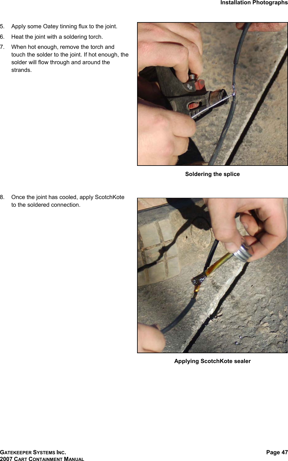
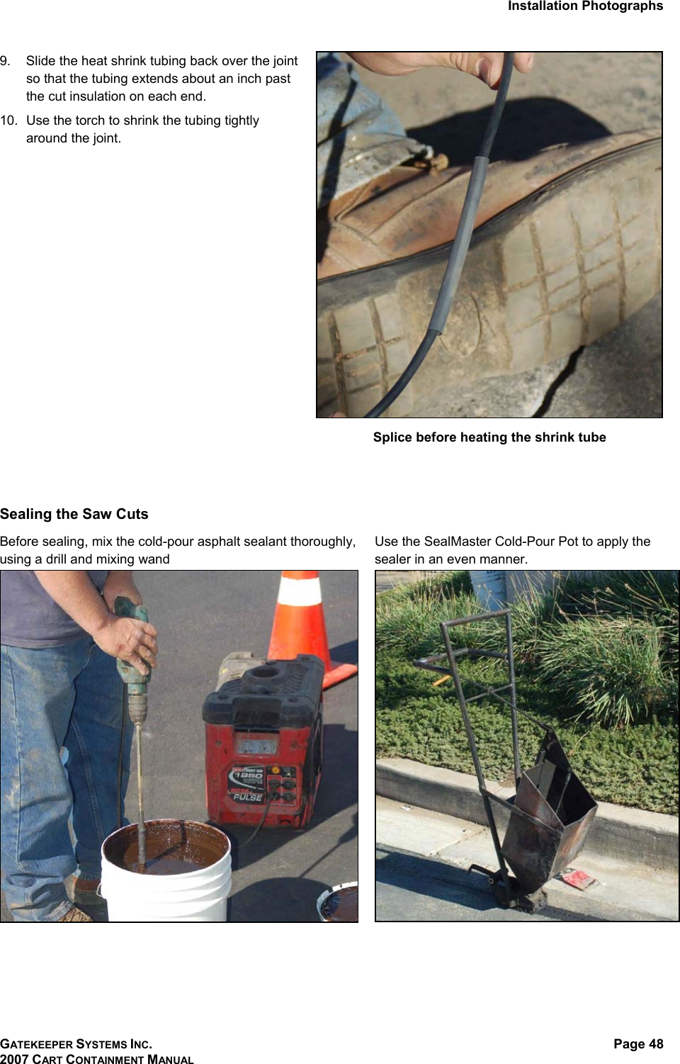
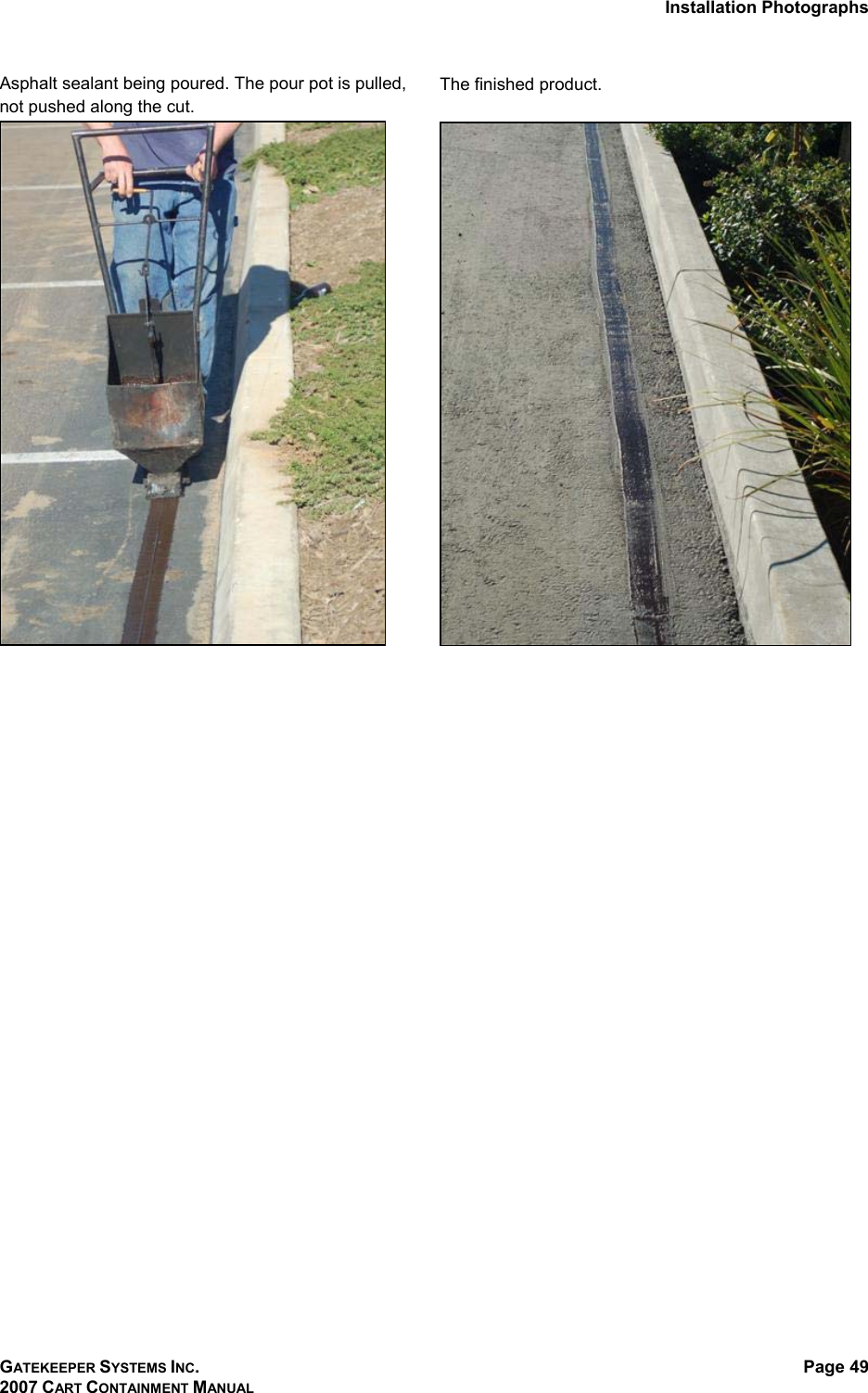
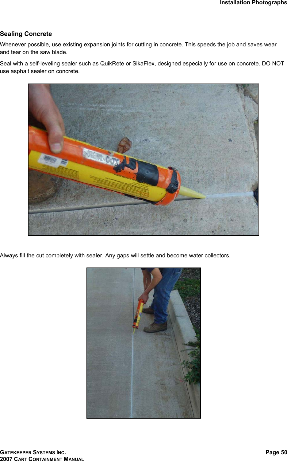
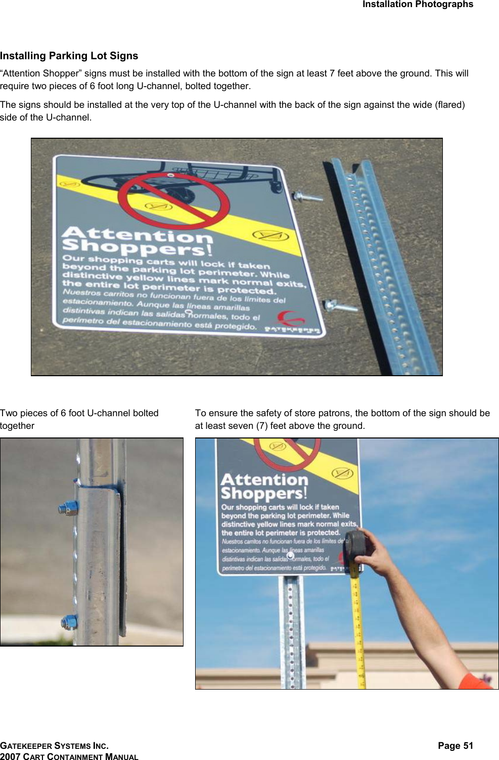
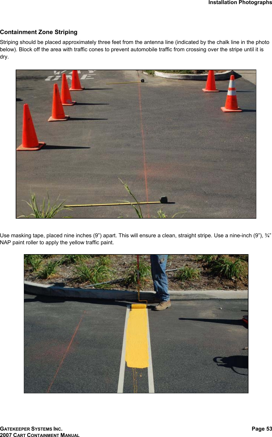
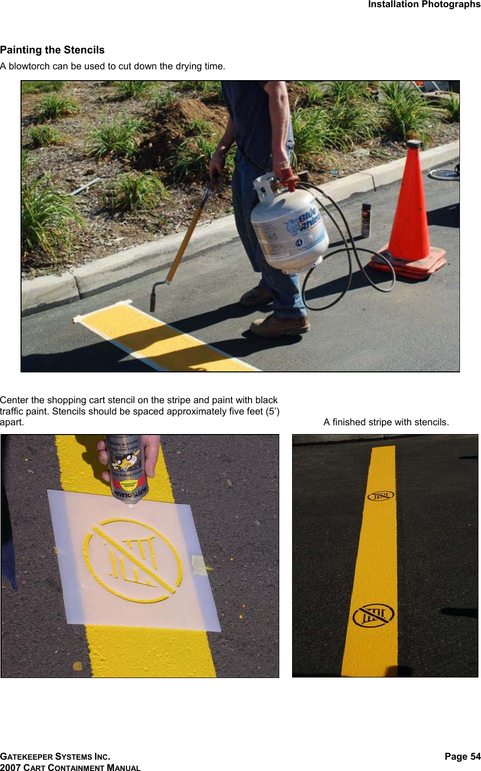
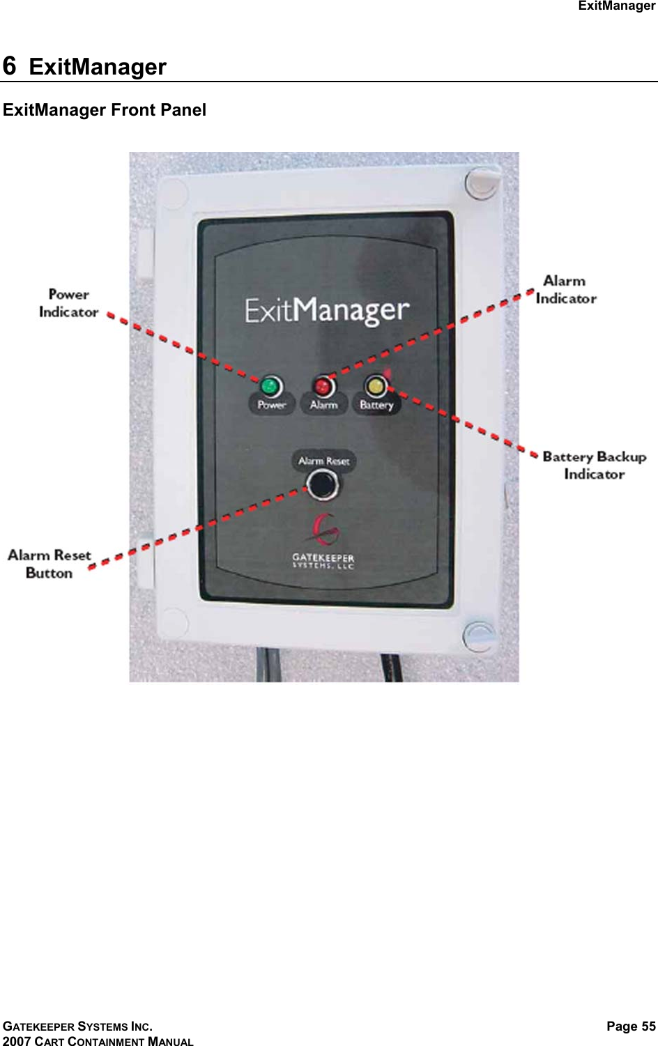
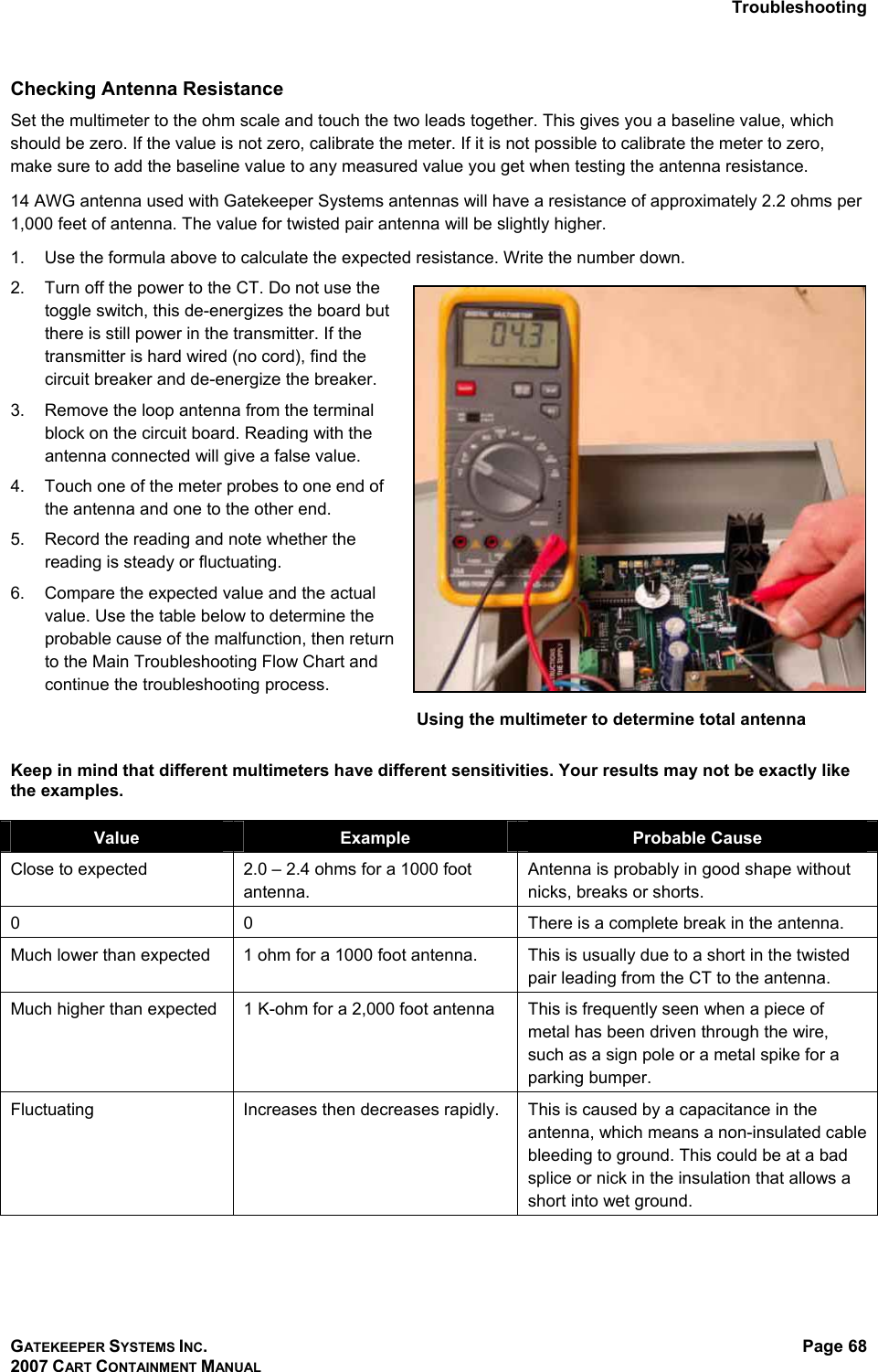
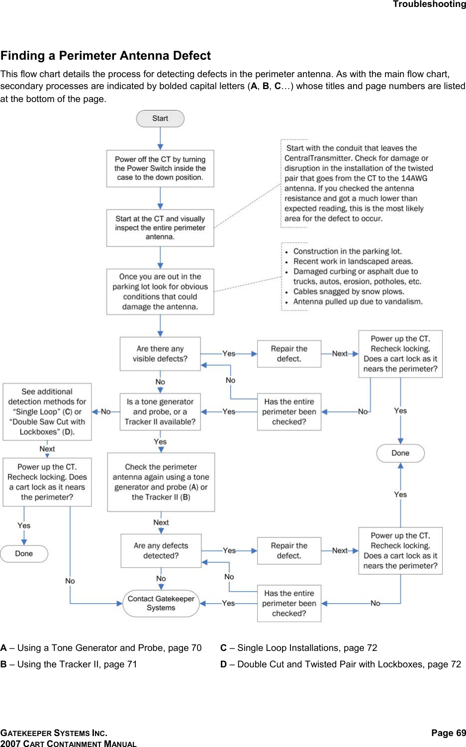
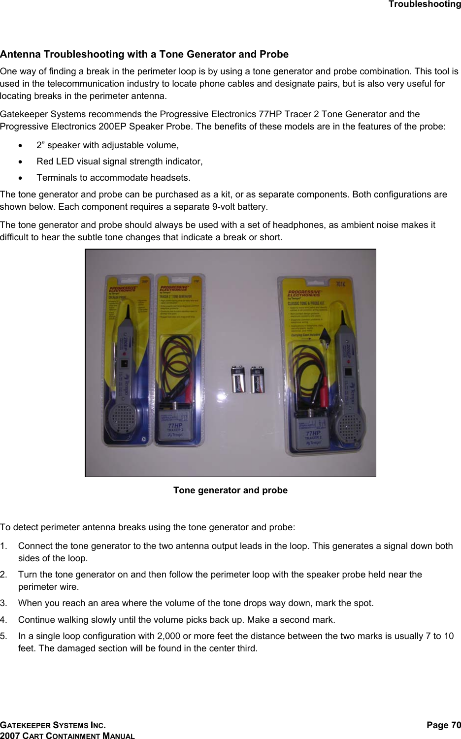
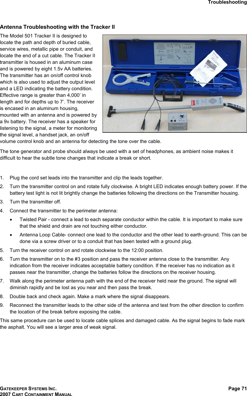
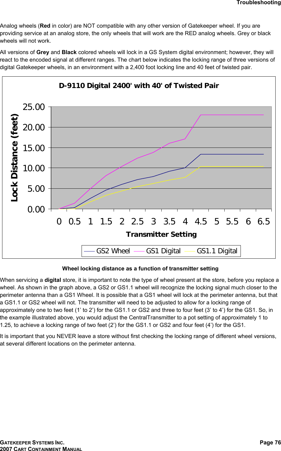
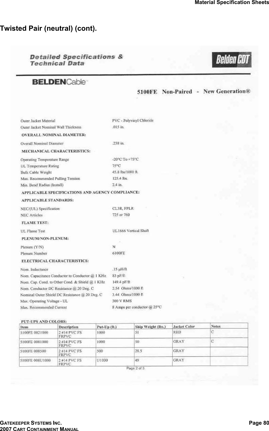
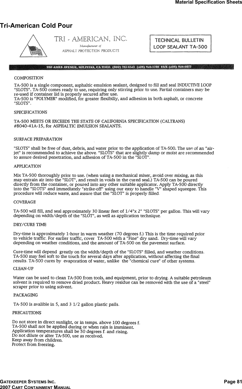
Users Manual Part 2